
58GE142 - Grinder Graphite - Free user manual and instructions
Find the device manual for free 58GE142 Graphite in PDF.
| Brand | Graphite |
| Model | 58GE142 |
| Product type | Cordless angle grinder |
| Power supply | Li-Ion battery 18 V DC |
| No-load speed | 0 – 3500 / 6500 / 9200 min⁻¹ (3 speeds) |
| Max. disc diameter | 125 mm |
| Spindle thread | M14 |
| IP protection class | IPX0 |
| Electrical protection class | III |
| Weight | 1.362 kg |
| Production year | 2023 |
| Main functions | Grinding, cutting, sanding, wire brushing |
| Motor type | Brushless |
| Protection guard | Tool-free orientation with locking lever |
| Auxiliary handle | Included, mountable in two positions |
| Switch | Safety switch with on/off position |
| Battery charge indicator | 3 LEDs on the battery |
| Maintenance and cleaning | Clean with a dry cloth or low-pressure compressed air; do not use water or solvent |
| Safety | Spindle lock, brake (quick stop), protection against accidental restarts |
| Spare parts and repairability | Repairs only by an authorized center; parts available from the manufacturer |
| General information | Delivered with battery and charger; dry use only; do not use for polishing |
Frequently Asked Questions - 58GE142 Graphite
User questions about 58GE142 Graphite
0 question about this device. Answer the ones you know or ask your own.
Ask a new question about this device
Download the instructions for your Grinder in PDF format for free! Find your manual 58GE142 - Graphite and take your electronic device back in hand. On this page are published all the documents necessary for the use of your device. 58GE142 by Graphite.
USER MANUAL 58GE142 Graphite
natural_image
Black and white photo of a GRAPHITE GRAPHTE power tool with adjustable grip and blade (no visible text or symbols)58GE142
10 ^* LAT DOSTĘPNOŚCI CZĘŚCI ZAMIENNYCH
natural_image
Icon of a person reading a book inside a circle (no text or symbols)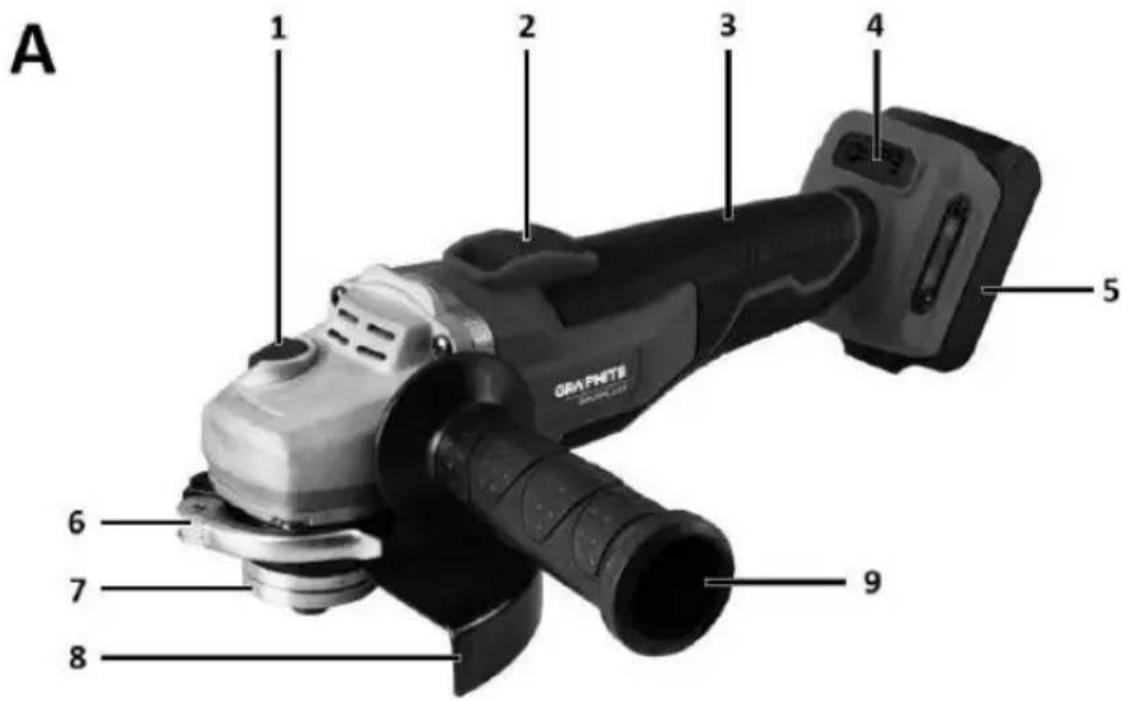
B

PL INSTRUKCJA ORYGINALNA (OBSŁUGI)......4
EN TRANSLATION (USER) MANUAL....9
DE ÜBERSETZUNG (BENUTZERHANDBUCH)......14

TRANSLATION (USER) MANUAL
Angle grinder: 59GE142
NOTE: BEFORE USING THE EQUIPMENT, PLEASE READ THIS MANUAL CAREFULLY AND KEEP IT FOR FUTURE REFERENCE. PERSONS WHO HAVE NOT READ THE INSTRUCTIONS SHOULD NOT CARRY OUT ASSEMBLY, ADJUSTMENT OR OPERATION OF THE EQUIPMENT.
SPECIFIC SAFETY PROVISIONS
NOTE!
Read the operating instructions carefully, follow the warnings and safety conditions contained therein. The appliance has been designed for safe operation. Nevertheless: installation, maintenance and operation of the appliance can be dangerous. Following the following procedures will reduce the risk of fire, electric shock, injury and will reduce the installation time of the appliance
READ THE USER MANUAL CAREFULLY TO FAMILIARISE YOURSELF WITH THE APPLIANCE KEEP THIS MANUAL FOR FUTURE REFERENCE.
SAFETY RULES
SPECIAL PROVISIONS FOR THE SAFE OPERATION OF ANGLE GRINDERS
SAFETY INSTRUCTIONS FOR SANDING, GRINDING WITH SANDPAPER, WORKING WITH WIRE BRUSHES AND CUTTING WITH A GRINDING WHEEL
- This machine can be used as a normal sander, a sandpaper sander, a wire brush sander and as a grinding wheel cutting machine. Follow all safety instructions, instructions, descriptions and data supplied with the machine.
Failure to comply with the following instructions may present a danger of electric shock, fire and/or serious injury.
- This device must not be used for polishing. Use of the device for other than the intended work activity may result in hazards and injuries.
- Do not use an accessory that is not specifically intended and recommended by the manufacturer for the appliance. The fact that an accessory can be fitted to an appliance is no guarantee of safe use.
- The permissible speed of the working tool used must not be less than the maximum speed indicated on the equipment.
A work tool rotating faster than the permissible speed may break and parts of the tool may splinter.
- The outer diameter and thickness of the working tool must correspond to the dimensions of the equipment. Work tools with incorrect dimensions cannot be sufficiently shielded or inspected.
- Work tools with a threaded insert must fit exactly onto the thread on the spindle. For flange-mounted work tools, the diameter of the work tool bore must match the diameter of the flange. Work tools that cannot fit exactly on the machine will rotate unevenly, vibrate very strongly and may cause loss of control of the machine.
- Under no circumstances should damaged work tools be used. Inspect the tooling before each use, e.g. grinding wheels for chipping and cracks, sanding pads for cracks, abrasion or heavy wear, wire brushes for loose or broken wires. If a machine or work tool has fallen, check it for damage or use another undamaged tool. If the tool has been checked and fixed, the machine should be turned on to its highest speed for one minute, taking care that the operator and bystanders in the vicinity are out of the zone of the rotating tool. Damaged tools usually break during this testing time.
- Personal protective equipment must be worn. Depending on the type of work, wear a protective mask covering the entire face, eye protection or safety goggles. If necessary, use a dust mask, hearing protection, protective gloves or a special apron to protect against small particles of abraded and machined material. Protect your eyes from airborne foreign bodies generated during work. A dust mask and respiratory protection must filter out dust generated during work. Exposure to noise over a prolonged period of time, may lead to hearing loss.
- Care must be taken to keep bystanders at a safe distance from the appliance's coverage area. Anyone in the vicinity of the working machine must use personal protective equipment. Workpiece splinters or broken work tools can splinter and cause injury even outside the immediate range zone.
- When carrying out work where the tool could encounter concealed electrical wires, hold the tool only by the insulated surfaces of the
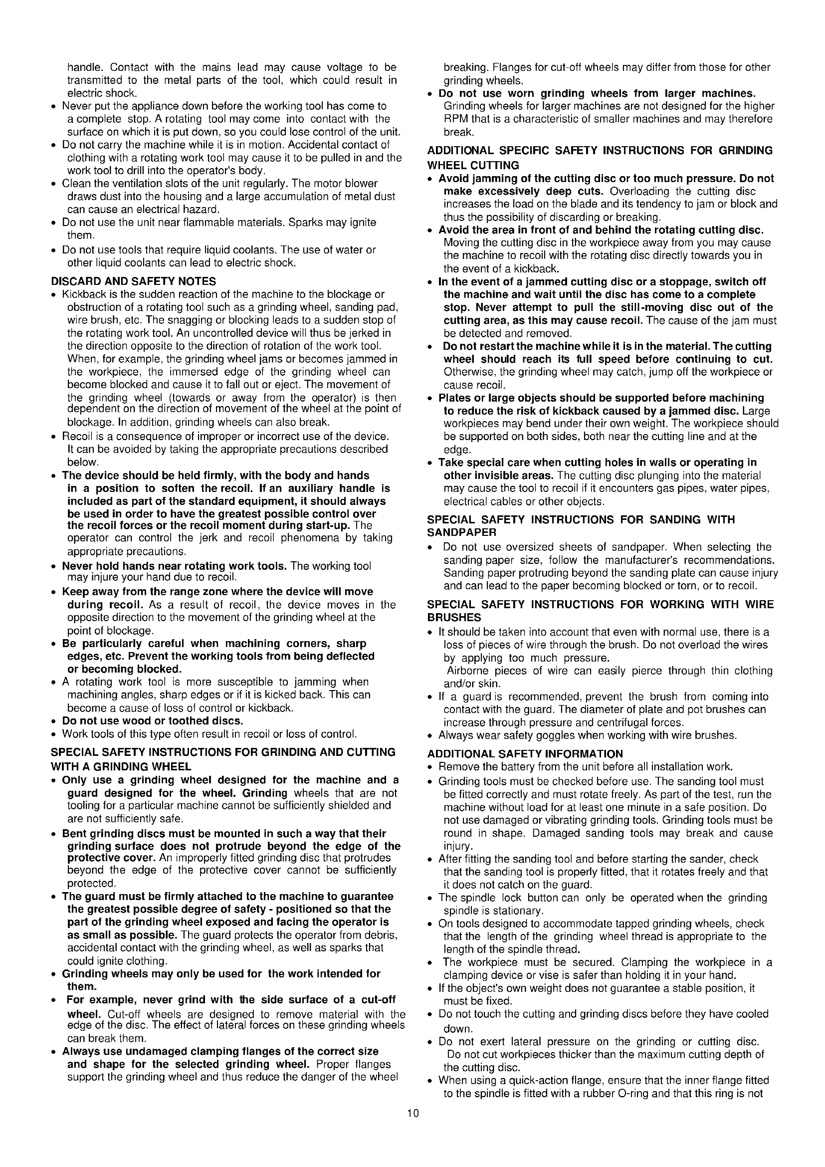
handle. Contact with the mains lead may cause voltage to be transmitted to the metal parts of the tool, which could result in electric shock.
- Never put the appliance down before the working tool has come to a complete stop. A rotating tool may come into contact with the surface on which it is put down, so you could lose control of the unit.
- Do not carry the machine while it is in motion. Accidental contact of clothing with a rotating work tool may cause it to be pulled in and the work tool to drill into the operator's body.
- Clean the ventilation slots of the unit regularly. The motor blower draws dust into the housing and a large accumulation of metal dust can cause an electrical hazard.
- Do not use the unit near flammable materials. Sparks may ignite them.
- Do not use tools that require liquid coolants. The use of water or other liquid coolants can lead to electric shock.
DISCARD AND SAFETY NOTES
- Kickback is the sudden reaction of the machine to the blockage or obstruction of a rotating tool such as a grinding wheel, sanding pad, wire brush, etc. The snagging or blocking leads to a sudden stop of the rotating work tool. An uncontrolled device will thus be jerked in the direction opposite to the direction of rotation of the work tool. When, for example, the grinding wheel jams or becomes jammed in the workpiece, the immersed edge of the grinding wheel can become blocked and cause it to fall out or eject. The movement of the grinding wheel (towards or away from the operator) is then dependent on the direction of movement of the wheel at the point of blockage. In addition, grinding wheels can also break.
- Recoil is a consequence of improper or incorrect use of the device. It can be avoided by taking the appropriate precautions described below.
- The device should be held firmly, with the body and hands in a position to soften the recoil. If an auxiliary handle is included as part of the standard equipment, it should always be used in order to have the greatest possible control over the recoil forces or the recoil moment during start-up. The operator can control the jerk and recoil phenomena by taking appropriate precautions.
- Never hold hands near rotating work tools. The working tool may injure your hand due to recoil.
- Keep away from the range zone where the device will move during recoil. As a result of recoil, the device moves in the opposite direction to the movement of the grinding wheel at the point of blockage.
- Be particularly careful when machining corners, sharp edges, etc. Prevent the working tools from being deflected or becoming blocked.
- A rotating work tool is more susceptible to jamming when machining angles, sharp edges or if it is kicked back. This can become a cause of loss of control or kickback.
- Do not use wood or toothed discs.
- Work tools of this type often result in recoil or loss of control.
SPECIAL SAFETY INSTRUCTIONS FOR GRINDING AND CUTTING WITH A GRINDING WHEEL
- Only use a grinding wheel designed for the machine and a guard designed for the wheel. Grinding wheels that are not tooling for a particular machine cannot be sufficiently shielded and are not sufficiently safe.
- Bent grinding discs must be mounted in such a way that their grinding surface does not protrude beyond the edge of the protective cover. An improperly fitted grinding disc that protrudes beyond the edge of the protective cover cannot be sufficiently protected.
- The guard must be firmly attached to the machine to guarantee the greatest possible degree of safety - positioned so that the part of the grinding wheel exposed and facing the operator is as small as possible. The guard protects the operator from debris, accidental contact with the grinding wheel, as well as sparks that could ignite clothing.
- Grinding wheels may only be used for the work intended for them.
- For example, never grind with the side surface of a cut-off wheel. Cut-off wheels are designed to remove material with the edge of the disc. The effect of lateral forces on these grinding wheels can break them.
- Always use undamaged clamping flanges of the correct size and shape for the selected grinding wheel. Proper flanges support the grinding wheel and thus reduce the danger of the wheel
breaking. Flanges for cut-off wheels may differ from those for other grinding wheels.
- Do not use worn grinding wheels from larger machines. Grinding wheels for larger machines are not designed for the higher RPM that is a characteristic of smaller machines and may therefore break.
ADDITIONAL SPECIFIC SAFETY INSTRUCTIONS FOR GRINDING WHEEL CUTTING
- Avoid jamming of the cutting disc or too much pressure. Do not make excessively deep cuts. Overloading the cutting disc increases the load on the blade and its tendency to jam or block and thus the possibility of discarding or breaking.
- Avoid the area in front of and behind the rotating cutting disc. Moving the cutting disc in the workpiece away from you may cause the machine to recoil with the rotating disc directly towards you in the event of a kickback.
- In the event of a jammed cutting disc or a stoppage, switch off the machine and wait until the disc has come to a complete stop. Never attempt to pull the still-moving disc out of the cutting area, as this may cause recoll. The cause of the jam must be detected and removed.
- Do not restart the machine while it is in the material. The cutting wheel should reach its full speed before continuing to cut. Otherwise, the grinding wheel may catch, jump off the workpiece or cause recoil.
- Plates or large objects should be supported before machining to reduce the risk of kickback caused by a jammed disc. Large workpieces may bend under their own weight. The workpiece should be supported on both sides, both near the cutting line and at the edge.
- Take special care when cutting holes in walls or operating in other invisible areas. The cutting disc plunging into the material may cause the tool to recoil if it encounters gas pipes, water pipes, electrical cables or other objects.
SPECIAL SAFETY INSTRUCTIONS FOR SANDING WITH SANDPAPER
- Do not use oversized sheets of sandpaper. When selecting the sanding paper size, follow the manufacturer's recommendations. Sanding paper protruding beyond the sanding plate can cause injury and can lead to the paper becoming blocked or torn, or to recoil.
SPECIAL SAFETY INSTRUCTIONS FOR WORKING WITH WIRE BRUSHES
- It should be taken into account that even with normal use, there is a loss of pieces of wire through the brush. Do not overload the wires by applying too much pressure. Airborne pieces of wire can easily pierce through thin clothing and/or skin.
- If a guard is recommended, prevent the brush from coming into contact with the guard. The diameter of plate and pot brushes can increase through pressure and centrifugal forces.
• Always wear safety goggles when working with wire brushes.
ADDITIONAL SAFETY INFORMATION
- Remove the battery from the unit before all installation work.
- Grinding tools must be checked before use. The sanding tool must be fitted correctly and must rotate freely. As part of the test, run the machine without load for at least one minute in a safe position. Do not use damaged or vibrating grinding tools. Grinding tools must be round in shape. Damaged sanding tools may break and cause injury.
- After fitting the sanding tool and before starting the sander, check that the sanding tool is properly fitted, that it rotates freely and that it does not catch on the guard.
- The spindle lock button can only be operated when the grinding spindle is stationary.
- On tools designed to accommodate tapped grinding wheels, check that the length of the grinding wheel thread is appropriate to the length of the spindle thread.
- The workpiece must be secured. Clamping the workpiece in a clamping device or vise is safer than holding it in your hand.
- If the object's own weight does not guarantee a stable position, it must be fixed.
- Do not touch the cutting and grinding discs before they have cooled down.
- Do not exert lateral pressure on the grinding or cutting disc. Do not cut workpieces thicker than the maximum cutting depth of the cutting disc.
- When using a quick-action flange, ensure that the inner flange fitted to the spindle is fitted with a rubber O-ring and that this ring is not
damaged. Also ensure that the surfaces of the outer flange and inner flange are clean.
- Use the quick-action flange only with abrasive and cutting discs. Use only undamaged and properly functioning flanges.
PROPER BATTERY HANDLING AND OPERATION
- The battery charging process should be under the control of the user.
- Avoid charging the battery at temperatures below 0 C.
- Only charge the batteries with the charger recommended by the manufacturer. The use of a charger designed to charge a different type of battery poses a risk of fire.
- When the battery is not in use, keep it away from metal objects such as paper clips, coins, keys nails, screws, or other small metal items that can short-circuit the battery terminals. Short-circuiting the battery terminals can cause burns or fire.
- In the event of damage and/or misuse of the battery, gases may be released. Ventilate the room, consult a doctor in case of discomfort. The gases may damage the respiratory tract.
- Fluid leakage from the battery can occur in extreme conditions. Liquid leaking from the battery can cause irritation or burns. If a leak is detected, proceed as follows:
- Carefully wipe off the liquid with a piece of cloth. Avoid contact of the liquid with the skin or eyes.
- if the liquid comes into contact with the skin, the relevant area on the body should be washed immediately with copious amounts of clean water, or neutralise the liquid with a mild acid such as lemon juice or vinegar.
- if the liquid gets into the eyes, rinse them immediately with plenty of clean water for at least 10 minutes and seek medical advice.
- Do not use a battery that is damaged or modified. Damaged or modified batteries may act unpredictably, leading to fire, explosion or danger of injury.
- The battery must not be exposed to moisture or water.
- Always keep the battery away from a heat source. Do not leave it in a high temperature environment for long periods of time (in direct sunlight, near radiators or anywhere where the temperature exceeds 50°C).
- Do not expose the battery to fire or excessive temperatures. Exposure to fire or temperatures above 130°C may cause an explosion.
NOTE: A temperature of 130^ C can be specified as 265^ F.
- All charging instructions must be followed, and the battery must not be charged at a temperature outside the range specified in the rating table in the operating instructions. Charging incorrectly or at temperatures outside the specified range can damage the battery and increase the risk of fire.
BATTERY REPAIR:
- Damaged batteries must not be repaired. Repairs to the battery are only permitted by the manufacturer or an authorised service centre.
- The used battery should be taken to a disposal centre for this type of hazardous waste.
SAFETY INSTRUCTIONS FOR THE CHARGER
- The charger must not be exposed to moisture or water. The ingress of water into the charger increases the risk of shock. The charger may only be used indoors in dry rooms.
- Unplug the charger from the mains before carrying out any maintenance or cleaning.
- Do not use the charger placed on a flammable surface (e.g. paper, textiles) or in the vicinity of flammable substances. Due to the charger's temperature increase during the charging process, there is a danger of fire.
- Check the condition of the charger, cable and plug each time before use. If damage is found - do not use the charger. Do not attempt to disassemble the charger. Refer all repairs to an authorised service workshop. Improper installation of the charger may result in a risk of electric shock or fire.
- Children and physically, emotionally or mentally challenged persons, as well as other persons whose experience or knowledge is insufficient to operate the charger with all safety precautions, should not operate the charger without the supervision of a responsible person. Otherwise there is a danger that the device will be mishandled resulting in injury.
- When the charger is not in use, it should be disconnected from the mains.
- All charging instructions must be followed, and the battery must not be charged at a temperature outside the range specified in the rating table in the operating instructions.
Charging incorrectly or at temperatures outside the specified range can damage the battery and increase the risk of fire.
CHARGER REPAIR
- A defective charger must not be repaired. Repairs to the charger are only permitted by the manufacturer or an authorised service centre.
- The used charger should be taken to a disposal centre for this type of waste.
- ATTENTION: The device is designed for indoor operation.
- Despite the use of an inherently safe design, the use of safety measures and additional protective measures, there is always a residual risk of injury during work.
Li-lon batteries can leak, catch fire or explode if they are heated to high temperatures or short-circuited. Do not store them in the car during hot and sunny days. Do not open the battery pack. Li-lon batteries contain electronic safety devices which, if damaged, can cause the battery to catch fire or explode.
PICTOGRAMS AND WARNINGS

-
Read the operating instructions, observe the warnings and safety conditions contained therein.
-
Wear safety goggles and ear protection and a protective mask.
-
Wear protective gloves.
-
For indoor use, protect from water and moisture.
-
Disconnect from power supply before repair and maintenance.
-
Keep children away from the appliance.
-
Risk of losing fingers, use caution.
-
Protect from rain.
-
Do not throw the cells into water, they pose a risk to the aquatic environment.
10.Do not throw cells into fire
11.Do not allow the cells to get hotter than 50°C
-
Do not dispose of with household waste.
-
Recyclable and selectively collected.
DESCRIPTION OF THE GRAPHIC ELEMENTS
The following numbering refers to the components of the device shown on the graphic pages of this manual.
| Designation Fig. A | Description |
| 1 | Spindle lock button |
| 2 | Switch |
| 3 | Main handle |
| 4 | Control panel |
| 5 | Battery socket |
| 6 | Blade guard lock |
| 7 | Shield mounting flanges |
| 8 | Shield |
| 9 | Additional handle |
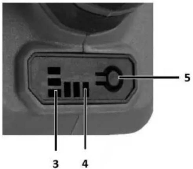
| Designation Fig. B | Description |
| 1 | Switch in the on position (I) |
| 2 | Switch in the off position (0) |
| 3 | Battery charge status indicator |
| 4 | Indicator of current gear |
| 5 | Shift button |
* There may be differences between the graphic and the actual product
CONSTRUCTION AND APPLICATION
The angle grinder is a hand-held power tool powered by a battery pack. It is driven by a DC brushless motor, transmitting the rotation via a geared angle gear. It can be used for both grinding and cutting. This type of power tool is widely used for removing all types of burrs from the surface of metal parts, surface treatment of welds, cutting through thin-walled pipes and small metal parts, etc. With the appropriate accessories, the angle grinder can be used not only for cutting and grinding, but also for cleaning e.g. rust, paint coatings, etc.
Its areas of use include extensive repair and construction work related to interior fittings, room adaptations, etc.
The appliance is intended for dry use only, not for polishing. Do not misuse the power tool.
Misuse.
- Do not handle materials containing asbestos. Asbestos is carcinogenic.
- Do not work with materials whose dusts are flammable or explosive. When working with the power tool, sparks are generated which may ignite the vapours emitted.
- Cut-off wheels must not be used for grinding work. Cut-off wheels work on the face and grinding with the side surface of such a wheel risks damaging the wheel, resulting in personal injury to the operator.
- Press the battery fixing button and slide the battery into the socket Fig. A5.
- Insert the charged battery into the handle holder until the battery retaining button audibly engages.
CHARGING THE BATTERY
The device is supplied with a partially charged battery. The battery should be charged in conditions where the ambient temperature is 4^0 C - 40^0 C. A new battery or one that has not been used for a long period of time will reach full power capability after approximately 3 - 5 charge and discharge cycles.
- Remove the battery from the device.
- Plug the charger into a mains socket (230 V AC).
- Insert the battery into the charger. Check that the battery is properly seated (inserted all the way).
- When the charger is plugged into a mains socket (230 V AC), the green LED on the charger will light up to indicate that the voltage is connected.
- When the battery is placed in the charger, a red LED will light up to indicate that the battery is being charged.
- At the same time, the green battery charge status LEDs light up pulsatingly in different patterns.
When the battery is charged, the LED on the charger lights up green and all the battery charge status LEDs light up continuously. After some time, the battery charge status LEDs turn off.
The battery should not be charged for more than 8 hours. Exceeding this time may damage the battery cells. The charger will not switch off automatically when the battery is fully charged. The green LED on the charger will remain lit. The battery charge status LED will turn off after a period of time. Disconnect the power supply before removing the battery from the charger socket. Avoid consecutive short charges. Do not recharge batteries after short use. A significant decrease in the time between necessary recharges indicates that the battery is worn out and should be replaced.
Batteries become warm during the charging process. Do not undertake work immediately after charging - wait until the battery has reached room temperature. This will prevent damage to the battery.
BATTERY CHARGE STATUS INDICATION
The battery is equipped with a charge status indication (3 LEDs). To check the charge status of the battery, press the battery charge status indicator button. When all LEDs are lit, the battery charge level is high. The lighting of 2 LEDs indicates partial discharge. The fact that only 1 diode is lit indicates that the battery is exhausted and needs to be recharged.
INSTALLATION AND ADJUSTMENT OF THE SHIELD
The blade guard protects the operator from debris, accidental contact with the work tool or sparks. It should always be fitted with extra care taken to ensure that its covering part faces the operator.
- The design of the blade guard attachment allows tool-free adjustment of the guard to the optimum position.
- Loosen and pull back the lever fig. A6 on the disc guard fig. A8.
- Turn the disc guard Fig. A8 to the desired position.
- Lock by lowering the lever Fig. A6.
- Removing and adjusting the disc guard is done in reverse order to its installation.
TOOL REPLACEMENT
• Work gloves must be worn during tool changing operations.
- The spindle lock button fig. A1 is only used to lock the spindle of the grinder when mounting or dismounting the work tool. It must not be used as a brake button while the disc is rotating. Doing so may damage the grinder or injure the user.
DISC MOUNTING
- In the case of grinding or cutting discs with a thickness of less than 3 mm, the nut of the outer flange fig. A7 must be screwed on flat on the disc side.
- Press the spindle lock button Fig. A1.
- Insert the special key (supplied) into the holes of the outer flange.
- Turn the key - loosen and remove the outer flange Fig. A7.
- Place the disc so that it is pressed against the surface of the inner flange, fig. A7.
- Screw on the outer flange, fig. A7, and tighten slightly with the special spanner.
- Removal of the discs is carried out in the reverse order to assembly. When assembling, the disc should be pressed against the surface of the inner flange and centred on its sub-flange.
FITTING OF WORKING TOOLS WITH THREADED HOLE
- Press the spindle lock button Fig. A1
- Remove the previously mounted implement - if fitted.
- Remove both flanges - inner flange and outer flange Fig. A7 - before installation.
- Screw the threaded part of the working tool onto the spindle and tighten slightly.
- Disassembly of threaded bore working tools is in reverse order to assembly.
MOUNTING OF ANGLE GRINDER IN ANGLE GRINDER STAND
It is permissible to use the angle grinder in a dedicated tripod for angle grinders, provided it is fitted correctly in accordance with the tripod manufacturer's assembly instructions.
Check the condition of the grinding wheel before using it. Do not use chipped, cracked or otherwise damaged grinding wheels. A worn wheel or brush should be replaced immediately with a new one before use. When you have finished working, always switch off the grinder and wait until the working tool has come to a complete standstill. Only then can the sander be put away. Do not brake the rotating grinding wheel by pressing it against the workpiece.
- Never overload the grinder. The weight of the power tool exerts sufficient pressure to operate the tool effectively. Overloading and excessive pressure can cause the power tool to break dangerously.
- If the sander falls during operation, it is essential to inspect and, if necessary, replace the working tool if it is found to be damaged or deformed.
-
Never strike the work tool against the work material.
-
Avoid bouncing and scraping with the disc, especially when working on corners, sharp edges, etc. (this can cause loss of control and kickback). (this may result in loss of control of the power tool and a kickback effect).
- Never use discs designed for cutting wood from circular saws. The use of such saw blades often results in a recoil phenomenon of the power tool, loss of control and can lead to injury to the operator.
ON/OFF
Hold the sander with both hands during start-up and operation.
The sander is equipped with a safety switch to prevent accidental start-up.
- Press the switch to position fig. B1 to start the unit.
- Push the switch to position fig. B2 to switch off the unit.
- After starting the grinder, wait until the grinding wheel has reached maximum speed before starting work. The switch must not be operated while the sander is switched on or off. The sander switch must only be operated when the power tool is away from the workpiece.
SHIFTING GEARS
NOTE: The grinder has a memory of the last speed setting that was set before the machine was switched off.
- The grinder has the ability to operate at 3 predefined speeds (see rating table). This can be checked on the display fig. B4.
• To change gear, press the button fig. B5 - Pressing the button fig. B5 changes the gear depending on the original setting. This is as follows with gear I set, pressing the Fig. B5 button shifts to gear II, pressing the Fig. B5 button again shifts to gear III, pressing the Fig. B5 button again shifts back to gear I.
- 1st gear lowest speed 1 diode
• 2nd gear medium speed 2 diodes
• 3rd gear highest speed 3 LEDs
CUTTING
- Cutting with an angle grinder can only be done in a straight line.
- Do not cut the material while holding it in your hand.
- Large workpieces should be supported and care should be taken that the support points are close to the cutting line and at the end of the material. Material placed stably will not tend to move during cutting.
- Small workpieces should be clamped e.g. in a vice, using clamps, etc. The material should be clamped so that the cutting point is close to the clamping element. This will ensure greater cutting precision.
- Do not allow vibration or tamping of the cutting disc, as this will impair the quality of the cut and may cause the cutting disc to break.
- No lateral pressure should be exerted on the cutting disc during cutting.
- Use the correct cutting disc depending on the material to be cut.
- When cutting through material, it is recommended that the direction of feed is in line with the direction of rotation of the cutting disc.
- The depth of cut depends on the diameter of the disc.
- Only discs with nominal diameters no larger than those recommended for the grinder model should be used.
- When making deep cuts (e.g. profiles, building blocks, bricks, etc.), do not allow the clamping flanges to come into contact with the workpiece.
- Cutting discs reach very high temperatures during operation - do not touch them with unprotected parts of the body before they have cooled down.
SANDING
Grinding work can be carried out using e.g. grinding discs, cup wheels, flap discs, discs with abrasive fleece, wire brushes, flexible discs for sandpaper, etc. Each type of disc and workpiece requires a suitable working technique and the use of appropriate personal protective equipment.
• Discs designed for cutting should not be used for sanding.
- Grinding discs are designed to remove material with the edge of the disc.
- Do not grind with the side of the disc. The optimum working angle for this type of disc is 30^ .
- Grinding work must only be carried out using grinding discs suitable for the material.
- When working with flap discs, abrasive fleece discs and flexible discs for sanding paper, care must be taken to ensure the correct angle of attack so that the flaps are parallel to the workpiece.
- Do not sand with the entire surface of the disc.
• These types of discs are used for machining flat surfaces.
- Wire brushes are mainly intended for cleaning profiles and hard-to-reach areas. They can be used to remove e.g. rust, paint coatings, etc. from material surfaces.
- Only work tools whose permissible speed is higher than or equal to the maximum speed of the angle grinder without load should be used.
Remove the battery from the unit before carrying out any installation, adjustment, repair or operation.
MAINTENANCE AND STORAGE
- It is recommended to clean the device immediately after each use.
- Do not use water or other liquids for cleaning.
- The unit should be cleaned with a dry piece of cloth or blown with low-pressure compressed air.
- Do not use any cleaning agents or solvents, as these may damage the plastic parts.
- Clean the ventilation slots in the motor housing regularly to prevent the unit from overheating.
- If excessive sparking occurs on the commutator, have the condition of the motor's carbon brushes checked by a qualified person.
• Always store the device in a dry place out of the reach of children. - Store the device with the battery removed.
- Any defects should be rectified by the manufacturer's authorised service department.
| Energy+ angle grinder 58GE142 | |
| Parameter | Value |
| Battery voltage | 18 V DC |
| Rated speed | 0-3500/6500/9200 min ^1 |
| Max. disc diameter | 125 mm |
| Spindle threads | M14 |
| IP protection class | IPX0 |
| Protection class | III |
| Mass | 1,362 kg |
| Year of production | 2023 |
| 58GE142 indicates both the type and the designation of the machine | |
NOISE AND VIBRATION DATA
| Sound pressure level | L_pA = 82.01 dB (A) K=3dB (A) |
| Sound power level | L_WA = 90.01 dB (A) K=3dB (A) |
| Vibration acceleration value(main handle) | a_h = 6.120 m/s^2 K=1.5 m/s^2 |
| Vibration acceleration value(auxiliary handle) | a_h = 4.498 m/s^2 K=1.5 m/s^2 |
Information on noise and vibration
The noise emission level of the equipment is described by: the emitted sound pressure level L_PA and the sound power level L_WA (where K denotes measurement uncertainty). The vibrations emitted by the equipment are described by the vibration acceleration value a_h (where K is the measurement uncertainty).
The sound pressure level L_pA , the sound power level L_wA and the vibration acceleration value a_h given in these instructions were measured in accordance with EN 62841-1. The vibration level a_h given can be used for comparison of equipment and for preliminary assessment of vibration exposure.
The vibration level quoted is only representative of the basic use of the unit. If the unit is used for other applications or with other work tools, the vibration level may change. A higher vibration level will be influenced by insufficient or too infrequent maintenance of the unit. The reasons given above may result in increased vibration exposure during the entire working period.
In order to accurately estimate vibration exposure, it is necessary to take into account periods when the device is switched off or when it is switched on but not used for work. Once all factors have been accurately estimated, the total vibration exposure may turn out to be much lower.
In order to protect the user from the effects of vibration, additional safety measures should be implemented, such as cyclical maintenance of the machine and working tools, securing an adequate hand temperature and proper work organisation.
ENVIRONMENTAL PROTECTION
Electrically-powered products should not be disposed of with household waste, but should be taken to appropriate facilities for disposal. Conta your product dealer or local authority for information on disposal. Was electrical and electronic equipment contains environmentally inert substances. Equipment that is not recycled poses a potential risk to the environment and human health.
"Grupa Topex Spółka z ograniczoną odpowiedzialnością" Spółka komandytowa with its registered office in Warsaw, ul. Pograniczna 2/4 (hereinafter: "Grupa Topex") informs that all copyrights to the content of this manual (hereinafter: "Manual"), including, among others. Its text, photographs, diagrams, drawings, as well as its composition, belong exclusively to Grupa Topex and are subject to legal protection under the Act of 4 February 1994 on Copyright and Related Rights (Journal of Laws 2006 No. 90 Poz. 631, as amended). Copying, processing, publishing, modification for commercial purposes of the entire Manual and its individual elements, without the consent of Grupa Topex expressed in writing, is strictly prohibited and may result in civil and criminal liability.
EC Declaration of Conformity
Manufacturer: Grupa Topex Sp. z o.o. Sp.k., Pograniczna 2/4 02-285
Warszawa
Product: Cordless angle grinder
Model: 58GE142
Trade name: GRAPHITE
Serial number: 00001 ÷ 99999
This declaration of conformity is issued under the sole responsibility of the manufacturer.
The product described above complies with the following documents:
Machinery Directive 2006/42/EC
Electromagnetic Compatibility Directive 2014/30/EU
RoHS Directive 2011/65/EU as amended by Directive 2015/863/EU
And meets the requirements of the standards:
EN 62841-1:2015+A11; EN IEC 62841-2-3:2021+A11
EN IEC 55014-1:2021; EN IEC 55014-2:2021;
EN IEC 63000:2018
This declaration relates only to the machinery as placed on the market and does not include components
added by the end user or carried out by him/her subsequently.
Name and address of the EU resident person authorised to prepare the technical dossier:
Signed on behalf of:
Grupa Topex Sp. z o.o. Sp.k.
TOPEX GROUP Quality Officer
Warsaw, 2023-12-22
INSTRUCTIUNI DE SIGURANTĂ PENTRU ÎNCĂRCĂTOR
OHUTUSJUHISED LAADIJA JAOKS
VERTALING (GEBRUIKERS)HANDLEIDING
REPARATIE VAN ACCU'S:
WERKING VAN HET APPARAAT
REMPLACEMENT D'OUTILS
Directive Machines 2006/42/CE
- TRANSLATION (USER) MANUAL
- Angle grinder: 59GE142
- SPECIFIC SAFETY PROVISIONS
- NOTE!
- READ THE USER MANUAL CAREFULLY TO FAMILIARISE YOURSELF WITH THE APPLIANCE KEEP THIS MANUAL FOR FUTURE REFERENCE.
- SAFETY RULES
- SPECIAL PROVISIONS FOR THE SAFE OPERATION OF ANGLE GRINDERS
- SAFETY INSTRUCTIONS FOR SANDING, GRINDING WITH SANDPAPER, WORKING WITH WIRE BRUSHES AND CUTTING WITH A GRINDING WHEEL
- DISCARD AND SAFETY NOTES
- SPECIAL SAFETY INSTRUCTIONS FOR GRINDING AND CUTTING WITH A GRINDING WHEEL
- ADDITIONAL SPECIFIC SAFETY INSTRUCTIONS FOR GRINDING WHEEL CUTTING
- SPECIAL SAFETY INSTRUCTIONS FOR SANDING WITH SANDPAPER
- SPECIAL SAFETY INSTRUCTIONS FOR WORKING WITH WIRE BRUSHES
- ADDITIONAL SAFETY INFORMATION
- PROPER BATTERY HANDLING AND OPERATION
- BATTERY REPAIR:
- SAFETY INSTRUCTIONS FOR THE CHARGER
- CHARGER REPAIR
- DESCRIPTION OF THE GRAPHIC ELEMENTS
- CONSTRUCTION AND APPLICATION
- The appliance is intended for dry use only, not for polishing. Do not misuse the power tool.
- Misuse.
- CHARGING THE BATTERY
- BATTERY CHARGE STATUS INDICATION
- INSTALLATION AND ADJUSTMENT OF THE SHIELD
- The blade guard protects the operator from debris, accidental contact with the work tool or sparks. It should always be fitted with extra care taken to ensure that its covering part faces the operator.
- TOOL REPLACEMENT
- DISC MOUNTING
- FITTING OF WORKING TOOLS WITH THREADED HOLE
- MOUNTING OF ANGLE GRINDER IN ANGLE GRINDER STAND
- ON/OFF
- Hold the sander with both hands during start-up and operation.
- SHIFTING GEARS
- CUTTING
- SANDING
- MAINTENANCE AND STORAGE
- Information on noise and vibration
- ENVIRONMENTAL PROTECTION
- EC Declaration of Conformity
- Machinery Directive 2006/42/EC
- Electromagnetic Compatibility Directive 2014/30/EU
- EN IEC 63000:2018
- INSTRUCTIUNI DE SIGURANTĂ PENTRU ÎNCĂRCĂTOR
- OHUTUSJUHISED LAADIJA JAOKS
- VERTALING (GEBRUIKERS)HANDLEIDING
- REPARATIE VAN ACCU'S:
- WERKING VAN HET APPARAAT
- REMPLACEMENT D'OUTILS
Brand : Graphite
Model : 58GE142
Category : Grinder