59G175 - Grinder Graphite - Free user manual and instructions
Find the device manual for free 59G175 Graphite in PDF.

| Product type | Angle grinder |
| Brand | Graphite |
| Model | 59G175 |
| Supply voltage | 230 V AC |
| Frequency | 50 Hz |
| Rated power | 750 W |
| Rotational speed range | 3,000 – 12,000 min⁻¹ (adjustable) |
| Max. grinding wheel diameter | 125 mm |
| Grinding wheel bore | 22.2 mm |
| Spindle thread | M14 |
| Protection class | II |
| Weight | 1.8 kg |
| Year of manufacture | 2020 |
| Sound pressure level (cutting) | LpA = 82.9 dB(A) K=3 dB(A) |
| Sound power level (grinding) | LwA = 94.3 dB(A) K=3 dB(A) |
| Vibration acceleration value (cutting/main handle) | 2.978 m/s² K=1.5 m/s² |
| Vibration acceleration value (grinding/main handle) | 2.565 m/s² K=1.5 m/s² |
| Main functions | Grinding, cutting, brushing, sanding |
| Supplied accessories | Protection guard, special key, auxiliary handle |
| Maintenance | Clean ventilation slots, replace carbon brushes (worn <5 mm) |
| Safety | Wear PPE (goggles, gloves, mask), use the protection guard, do not use for polishing |
| Repairability | Replace carbon brushes by a qualified professional, use original parts |
| Area of use | Dry indoor, do not process asbestos or explosive materials |
Frequently Asked Questions - 59G175 Graphite
User questions about 59G175 Graphite
0 question about this device. Answer the ones you know or ask your own.
Ask a new question about this device
Download the instructions for your Grinder in PDF format for free! Find your manual 59G175 - Graphite and take your electronic device back in hand. On this page are published all the documents necessary for the use of your device. 59G175 by Graphite.
USER MANUAL 59G175 Graphite
natural_image
Icon of a person reading a book inside a circle (no text or symbols)PL INSTRUKCJA OBSŁUGI 6
GB INSTRUCTION MANUAL 11
DE BETRIEBSANLEITUNG....15
RU РУКОВОДСТВО ПО ЭКСПЛУАТАЦИИ ..... 19
UA ІНСТРУКЦІЯ З ЕКСПЛУАТАЦІЇ ..... 24
HU HASZNÁLATI UTASÍTÁS. 29
RO INSTRUCTIUNI DE DESERVIRE .....34
CZ INSTRUKCE K OBSLUZE....38
SK NÁVOD NA OBSLUHU....42
SL NAVODILA ZA UPORABO 46
LT APTARNAVIMO INSTRUKCIJA. 50
LV LIETOŠANAS INSTRUKCIJA 54
EE KASUTUSJUHEND 58
BG ИНСТРУКЦИЯ ЗА ОБСЛУЖВАНЕ ..... 62
HR UPUTE ZA UPOTREBU....67
SR UPUTSTVO ZA UPOTREBU 71
GR OΔΗΓΙΕΣ ΧΡΗΣΗΣ 75
ES INSTRUCCIONES DE USO....80
IT MANUALE PER L'USO 85
NL GEBRUIKSAANWIJZING 89
FR MANUEL D'INSTRUCTION 94
natural_image
Line drawing of a person using a grinding tool on a workbench (no text or symbols)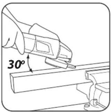
natural_image
Line drawing of a hand using a power tool to lift a surface, no text or symbols present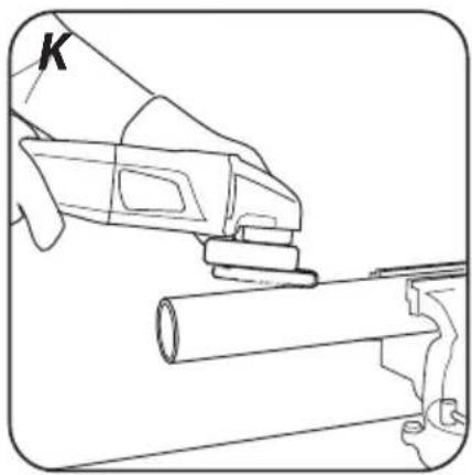
natural_image
Line drawing of a hand using a tool to cut a cylindrical object, no text or symbols present
INSTRUKCJA ORYGINALNA (OBSŁUGI) SZLIFIERKA KĄTOWA 59G175
UWAGA: PRZED PRZYSTĄPIENIEM DO UŻYTKOWANIA ELEKTRONARZĘDZIA NALEŻY UWAŻNIE PRZECZYTAĆ NINIEJSZĄ INSTRUKCJĘ I ZACHOWAĆ JĄ DO DALSZEGO WYKORZYSTANIA.
SZCZEGÓŁOWE PRZEPISY BEZPIECZEŃSTWA
/EC Declaration of Conformity/
/and fulfils requirements of the following Standards:/
/Signed for and on behalf of:/
/GRUPA TOPEX Quality Agent/

TRANSLATION OF THE ORIGINAL INSTRUCTIONS
ANGLE GRINDER 59G175
NOTE: BEFORE THE POWER TOOL IS USED FOR THE FIRST TIME, READ THIS INSTRUCTION MANUAL AND KEEP IT FOR FUTURE REFERENCE.
DETAILED SAFETY REGULATIONS
Safety Warnings Common for Grinding, Sanding, Wire Brushing, Polishing or Abrasive Cutting-Off Operations:
a) This power tool is intended to function as a grinder, sander, wire brush, or cut-off tool. Read all safety warnings, instructions, illustrations and specifications provided with this power tool. Failure to follow all instructions listed below may result in electric shock, fire and/or serious injury.
b) Operations such as polishing are not recommended to be performed with this power tool. Operations for which the power tool was not designed may create a hazard and cause personal injury.
c) Do not use accessories which are not specifically designed and recommended by the tool manufacturer. Just because the accessory can be attached to your power too, it does not assure safe operation.
d) The rated speed of the accessory must be at least equal to the maximum speed marked on the power tool. Accessories running faster than their speed can break and fly apart.
e) The outside diameter and the thickness of your accessory must be within the capacity rating of your power tool. Incorrectly sized accessories cannot be adequately guarded or controlled.
f) Threaded mounting of accessories must match the grinder spindle thread. For accessories mounted by flanges, the arbour hole of the accessory must fit the locating diameter of the flange. Accessories that do not match the mounting hardware of the power tool will run out of balance, vibrate excessively and may cause loss of control.
g) Do not use a damage accessory. Before each use inspect the accessory such as abrasive wheels for chips and cracks, backing pad for cracks, tear or excess wear, wire brush for loose or cracked wires. If power tool or accessory is dropped, inspect for damage or install an undamaged accessory. After inspecting and installing an accessory, position yourself and bystanders away from the plane of the rotating accessory and run the power tool at maximum no-load speed for one minute. Damaged accessories will normally break apart during this test time.
h) Wear personal protective equipment. Depending on application, use face shield, safety googles or safety glasses. As appropriate, wear dust mask, hearing protectors, gloves and workshop apron capable of stopping small abrasive or workpiece fragments. The eye protection must be capable of stopping flying debris generated by various operations. The dust mask or respirator must be capable of filtrating particles generated by your operation. Prolonged exposure to high intensity noise may cause hearing loos.
i) Keep bystanders a safe distance away from work area. Anyone entering the work area must wear personal protective equipment. Fragments of workpiece or of a broken accessory may fly away and cause injury beyond immediate area of operation.
j) Hold the power tool by insulated gripping surfaces only, when performing an operation where the cutting accessory may contact hidden wiring or its own cord. Cutting accessory contacting a "live" wire may make exposed metal parts of the power tool "live" and could give the operator an electric shock.
k) Position the cord clear of the spinning accessory. If you lose control, the cord may be cut or snagged and your hand or arm may be pulled into the spinning accessory.
I) Never lay the power tool down until the accessory has come to a complete stop. The spinning accessory may grab the surface and pull the power tool out of your control.
m) Do not run the power tool while carrying it at your side. Accidental contact with the spinning accessory could snag your clothing, pulling the accessory into your body.
n) Regularly clean the power tool's air vents. The motor's fan will draw the dust inside the housing and excessive accumulation of powdered metal may cause electrical hazards.
o) Do not operate the power tool near flammable materials. Sparks could ignite these materials.
p) Do not use accessories that require liquid coolants. Using water or other liquid coolants may result in electrocution or shock. Kickback and Related Warnings
Kickback is a sudden reaction to a pinched or snagged rotating wheel, backing pad, brush or any other accessory. Pinching or snagging causes rapid stalling of the rotating accessory which in turn causes the uncontrolled power tool to be forced in the direction opposite of the accessory's rotation at the point of the binding.
For example, if an abrasive wheel is snagged or pinched by the workpiece, the edge of the wheel that is entering into the pinch point can dig into the surface of the material causing the wheel to climb out or kick out. The wheel may either jump toward or away from operator, depending on direction of the wheel's movement at the point of pinching. Abrasive wheels may also break under these conditions.
Kickback is the result of power tool misuse and/or incorrect operating procedures or conditions and can be avoided by taking proper precautions as given below.
a) Maintain a firm grip on the power tool and position your body and arm to allow you to resist kickback forces. Always use auxiliary handle, if provided, for maximum control over kickback or torque reaction during start-up. The operator can control torque reaction or kickback forces, if proper precautions are taken.
b) Never place your hand near the rotating accessory. Accessory may kickback over your hand.
c) Do not position your body in the area where power tool will move if kickback occurs. Kickback will propel the tool in direction opposite to the wheel's movement at the point of snagging.
d) Use special care when working corners, sharp edges etc. Avoid bouncing and snagging the accessory. Corners, sharp edges or bouncing have a tendency to snag the rotating accessory and cause loss of control of kickback.
e) Do not attach a saw chain woodcarving blade or toothed saw blade. Such blades create frequent kickback and loss of control.
Safety Warnings Specific for Grinding and Abrasive Cutting-Off Operations:
a) Use only wheel types that are recommended for your power tool and the specific guard designed for the selected wheel. Wheels for which the power tool was not designed cannot be adequately guarded and are unsafe.
b) The grinding surface of centre depressed wheels must be mounted below the plane of the guard lip. An improperly mounted wheel that projects through the plane of the guard lip cannot be adequately protected.
c) The guard must be securely attached to the power tool and positioned for maximum safety, so the least amount of wheel is exposed towards the operator. The guard helps to protect the operator from broken wheel fragments, accidental contact with wheel, and sparks that could ignite clothing.
d) Wheels must be used only for recommended applications. For example: do not grind with the side of cut-off wheel. Abrasive cut-off wheels are intended for peripheral grinding, side forces applied to these wheels may cause them to shatter.
e) Always use undamaged wheel flanges that are of correct size and shape for your selected wheel. Proper wheel flanges support the wheel thus reducing the possibility of wheel breakage. Flanges for cut-off wheels may be different from grinding wheel flanges.
f) Do not use worn down wheels from larger power tools. Wheel intended for larger power tool is not suitable for the higher speed of a smaller tool and may burst.
Additional Safety Warnings Specific for Abrasive Cutting-Off Operations:
a) Do not "jam" the cut-off wheel or apply excessive pressure. Do not attempt to make an excessive depth of cut. Overstressing the wheel increases the loading and susceptibility to twisting or binding of the wheel in the cut and the possibility of kickback or wheel breakage.
b) Do not position your body in line with and behind the rotating wheel. When the wheel, at the point of operation, is moving away from your body, the possible kickback may propel the spinning wheel and the power tool directly at you.
c) When wheel is binding or when interrupting a cut for any reason, switch off the power tool and hold the power tool motionless until the wheel comes to a complete stop. Never attempt to remove the cut-off wheel from the cut while the wheel is in motion otherwise kickback may occur. Investigate and take corrective action to eliminate the cause of wheel binding.
d) Do not restart the cutting operation in the workpiece. Let the wheel reach full speed and carefully re-enter the cut. The wheel may bind, walk up or kickback if the power tool is restarted in the workpiece.
e) Support panels or any oversized workpiece to minimize the risk of wheel pinching and kickback. Large workpieces tend to sag under their own weight. Support must be placed under the workpiece near the line of cut and near the edge of the workpiece on both sides of the wheel.
f) Use extra caution when making a "pocket cut" into existing walls or other blind areas. The protruding wheel may cut gas or water pipes, electrical wiring or objects that can cause kickback.
Safety Warnings Specific for Sanding Operations:
a) Do not use excessively oversized sanding disc paper. Follow manufacturers recommendations, when selecting sanding paper. Larger sanding paper extending beyond the sanding pad presents a laceration hazard and may cause snagging, tearing of the disk or kickback.
Safety Warnings Specific for Polishing Operations:
a) Do not allow any loose portion of the polishing bonnet or its attachment strings to spin freely. Tuck away or trim any loose attachment strings. Loose and spinning attachment strings can entangle your fingers or snag on the workpiece.
Safety Warnings Specific for Wire Brushing Operations:
a) Be aware that wire bristles are thrown by the brush even during ordinary operation. Do not overstress the wires by applying excessive load to the brush. The wire bristles can easily penetrate light clothing and/or skin.
b) If the use of a guard is recommended for wire brushing, do not allow any interference of the wire wheel or brush with the guard. Wire wheel or brush may expand in diameter due to work load and centrifugal forces.
Additional safety Warnings:
a) In tools adapted to attach grinding wheels with a threaded hole, check whether the thread length of the grinding wheel is suitable for the length of the spindle thread.
b) Secure the workpiece. Attaching the workpiece to the clamping device or vise is safer than holding it in your hand.
c) Do not touch the cutting and grinding discs until they have cooled down.
d) When using a quick-setting flange, make sure that the internal flange mounted on the spindle is equipped with a rubber O-ring and that the ring is undamaged. It should also be ensured that the surfaces of the external flange and the internal flange are clean.
e) Use the quick clamping flange only with abrasive and cutting discs. Only use undamaged and properly functioning flanges.
f) In the event of a temporary power outage in the network or after removing the plug from the power socket with the switch in the "on" position, before re-starting, unlock the switch and set it in the off position.
CAUTION! This device is designed to operate indoors. The design is assumed to be safe, protection measures and additional safety systems are used, nevertheless there is always a small risk of injuries at work.
Descriptions of used pictograms.

1 2 3 4

5
6
7
8
- Warning, take special precautions.
- Read the instruction manual, observe warnings and safety conditions included in it!
- Use personal protection equipment (safety goggles, ear protectors).
- Use safety gloves.
- Disconnect the power cord, before maintenance or repair works are begun.
- Keep out of reach of children.
- Protect against rain
- Protection class II
DESIGN AND APPLICATION
The angle grinder is a hand-held power tool with the II class isolation. The power tool is driven with a single-phase, commutator motor, whose rotational speed is reduced by means of an intersecting axis gear. The power tool can be used both for grinding and cutting. This type of power tools is widely used for removal of burrs from metal surfaces, weld surface processing, cutting light-wall tubes and other small metal objects etc. They are used in engineering industry, automotive and chemical industry. With the use of proper tools, the angle grinder can be used not only for cutting or grinding, but also for rust and paint coats removal.
The areas of its application include repair and construction works, not only related to metals. The angle grinder can also be used for cutting and grinding of construction materials, such as brick, paving stones, ceramic tiles, etc.
The power tool is designed for dry operation only and it must not be used for polishing. The power tool should be used according to its purpose.
Use inconsistent with its purpose
- Do not work materials that contain asbestos. Asbestos is carcinogenic.
- Do not work materials, whose dust is inflammable or explosive. During operation, the power tool produces sparks, which may ignite emitted vapours.
- Do not use cut-off wheels for grinding. The cut-off wheels are used to cut with its face, while grinding with lateral surface of such a cut-off wheel threatens with its damages and puts the operate in danger of injuries.
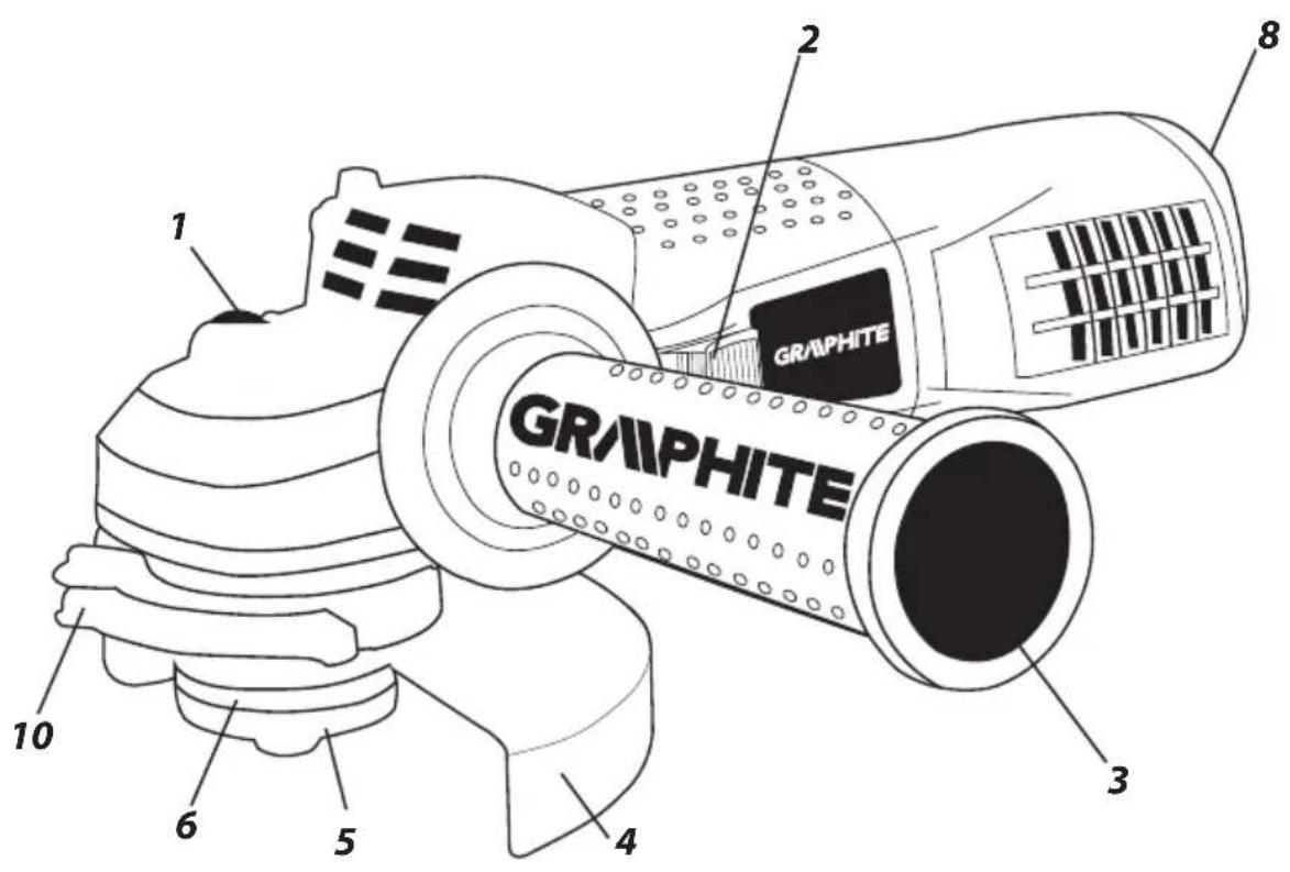
DESCRIPTION OF GRAPHIC PAGES
The below list refers to device components shown in the graphic pages of this instruction manual.
- Spindle lock button
- Switch
- Additional handle
- Grinding wheel cover
- External flange
- Internal flange
- Speed control dial
- Lever (grinding disc guard)
* There can be differences between the drawing and actual product.
DESCRIPTION OF USED GRAPHIC SIGNS

NOTE

WARNING
FITTING/SETTING

INFORMATION
EQUIPMENT AND ACCESSORIES
- Grinding wheel guard - 1 pce
- Socket spanner - 1 pce
- Additional handle - 1 pce
PREPARATION FOR WORK

ATTACHING THE ADDITIONAL HANDLE
The additional handle (3) is installed in one of the holes in the grinder head. It is recommended to use the grinder with the additional handle. When holding the grinder with both hands (also using the additional handle), there is less risk of touching the grinder wheel or brush with your hand, as well as of injuries during recoil.

INSTALLING AND ADJUSTING THE GRINDING WHEEL GUARD
The wheel guard protects the operator against flying broken pieces and accidental contact with a working tool or sparks. The guard should always be fitted. Special attention should be paid so that its covering part faces the operator.

- The design of the wheel guard mounting allows for toolless setting of the guard in an optimum position.
- Loosen and pull back the lever (10) on the wheel guard (4).
- Rotate the wheel guard (4) in a selected position.
- Lock by lowering the lever (10).
The removal and adjustment of the wheel guard are performed in a reverse order to its installation.

REPLACEMENT OF WORKING TOOLS
When working tools are replaced, wear working gloves at all times.

The spindle lock button (1) is only designed to lock the grinder spindle, when a working tool is installed or removed. Do not use it as a braking button, when the wheel rotates. Otherwise, the grinder may become damaged or the user may be injured.

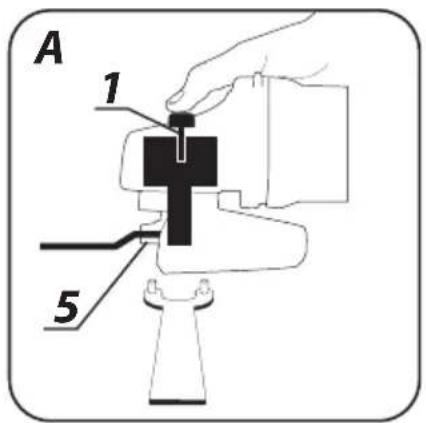
INSTALLING THE WHEELS
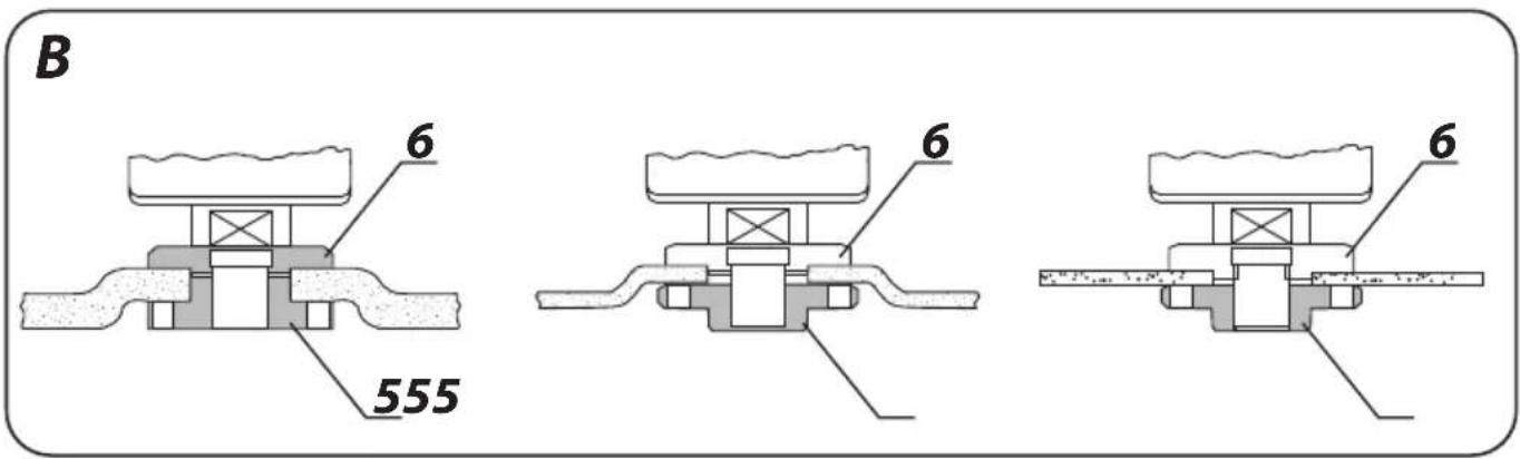
When grinding or cut-off wheels with the thickness below 3 mm are installed, the outer flange nut (5) should be tightened with the flat surface from the wheel side (fig. B).

- Press the spindle lock button (1).
- Insert the special key (included) into two holes of the outer flange (5) (fig. A).
- Rotate the key to loosen and remove the outer flange (5).
- Place the wheel so it is pressed against the surface of the inner flange (6).
- Tighten the outer flange (5) and slightly tighten it with the special key.

The wheel is removed in the reverse order. During installation, the wheel should be pressed against the surface of the inner flange (6) and seated centrally in the neck.

INSTALLING THE WORKING TOOLS WITH THREADED HOLES
- Press the spindle lock button (1).
- Remove a previously installed working tool, if it is installed.
- Both flanges should be removed before installation – the inner flange (6) and outer flange (5).
- Put the threaded part of a working tool onto the spindle and slightly tighten.
Working tools with threaded holes are removed in the reverse order.
INSTALLING THE ANGLE GRINDER ON A TRIPOD FOR ANGLE GRINDERS

The angle grinder can be used on a dedicated tripod for angle grinders, provided that it is correctly installed according to instructions of the manufacturer of a tripod.

Before the grinder is used, check condition of the grinding wheel.

Do not use chipped, broken or otherwise damaged grinding wheels. Worn grinding wheel or brush should be immediately replaced with new one before use. Once your work is completed, you should switch off the grinder and wait until it comes to a complete stop. Only then the grinder can be put aside. Do not brake a rotating grinding wheel by pressing it against a workpiece.
- Do not overload the grinder. The weight of the power tool exerts sufficient pressure to efficiently work with the tool. Overloading and excessive pressure may lead to dangerous cracking of the working tool.
- If the grinder is dropped during operation, it should be checked and a working tool might need to be replaced, when it is damaged or deformed.
- Never strike the workpiece with a working tool.
- Do not use the grinding wheel for hammering or stripping of the workpiece, especially when corners, sharp edges are worked, etc. (this may cause loss of control of the power tool and recoil).
- Do not use discs from circular saws intended for wood cutting. Failure to observe this recommendation may result in recoil of the power tool, loss of control and may lead to injuries of the operator.
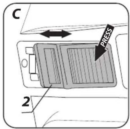
SWITCHING ON /SWITCHING OFF
When the grinder is switched on and operated, it should be held with both hands.
- Press the rear part of the switch (2).
- Move the switch (2) forwards - (towards the head) (fig. C).
- Press the front part of the switch for continuous operation.
- The switch will be automatically locked in the position for continuous operation.
- Press the rear part of the switch (2) to switch the tool off.
Once the grinder is switched on, wait until the grinding wheel reaches maximum speed and only then you can begin to work. During operation do not use the switch to switch the grinder on and off. The grinder switch can be used only when the power tool is moved away from the workpiece.
The tool is equipped with a switch with undervoltage release feature. In case of temporary mains power failure or connecting to mains socket with switch in ON position, the tool will not start. In such case move the switch to OFF position and switch it on again.
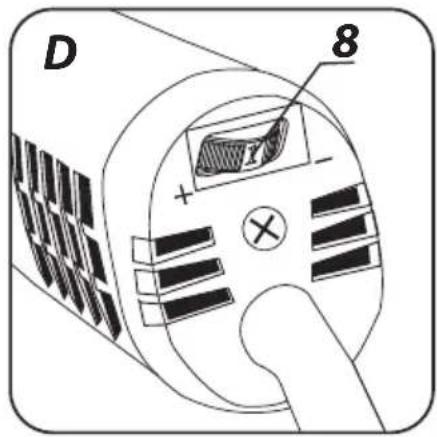
SPEED ADJUSTMENT
The speed adjustment dial (8) (fig. D) is located in the upper rear part of the grinder casing. The adjustment range is from 1 to 6. The rotational speed can be changed depending on your needs.
CUTTING
- The angle grinder can be used for cutting in a straight line only. - Do not cut a workpiece holding it in your hands.
- Large workpiece should be supported. Make sure the support points are located near the cutting line and at the ends of the workpiece. A stably located workpiece will not tend to move, when it is cut.
- Small workpieces should be fastened in a vice or using clamps, for example. The workpiece should be fastened so that it is cut near the fastening element. This will ensure higher cutting precision.
- Do not allow the cut-off wheel to vibrate or jump, since this will lower the quality of cutting and may cause the cut-off wheel to break.
- Do not exert lateral pressure onto the cut-off wheel during cutting.
- A proper cut-off wheel should be used depending on a workpiece type.
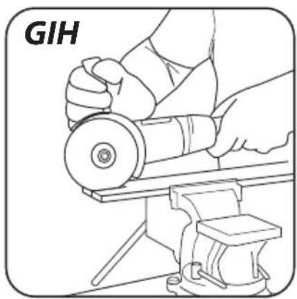
- When a workpiece is cut, it is recommended that a cutting direction is the same as rotation direction of the cut-off wheel. The cutting depth depends on a wheel diameter (fig. G).
- Only wheels with nominal diameters not larger than recommended for a given grinder model should be used.
- Do not allow the fastening flanges to contact a workpiece in case of deep cuts (e.g. sections, building blocks, bricks, etc.).
Cut-off wheels reach high temperatures during operation. It cannot be touched with uncovered body parts, before they cool down.
GRINDING


Grinding wheel, cup-type grinding wheels, flap wheels, wheels with abrasive fibre, wire brushes and flexible discs, etc. should be used for grinding. Each type of discs and workpiece requires proper working method and personal protective equipment.

Cut-off wheels should not be used for grinding.
Grinding discs are intended for removal of material with an edge of the disc.
- Do not use the lateral surface for grinding. The optimum working angle for this disc type is 30^ (fig. H).
- Works related to grinding can be performed only, when proper grinding discs are used for a given workpiece.

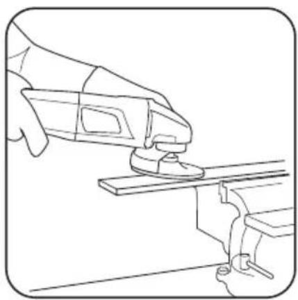
When flap wheels, discs with abrasive fibre and flexible discs for sandpaper are used, attention should be paid to the proper tool angle (fig. I).
- Do not grind with the entire surface of a wheel.
• This disc type should be used for working flat surfaces.

Wire brushes are mainly used for cleaning sections and hard-to-reach spaces. They can be used to remove rust, painting coats, etc. from a workpiece surface (fig. K).

Only such working tools can be used, whose permissible rotational speed is higher or equal to the maximum no load speed of the grinder.
Before any operations related to installation, adjustment, repairs or maintenance are commenced, the plug of the power cord should be disconnected from the socket.
MAINTENANCE AND STORAGE

- It is recommended to clean the tool after each use.
- Do not use water or other fluids for cleaning.
- The tool should be cleaned with a dry piece of cloth or blown with compressed air of low pressure.
- Do not use any cleaning agents or solvents, since they may damage plastic parts.
- Venting slots in the motor housing should be cleaned on a regular basis not to overload the tool.
- When the power cord is damaged, it should be replaced with the power cord of the same parameters. It should be performed by a qualified professional or the tool should be delivered to an authorised service shop.
- When the commutator sparks excessively, have the condition of motor carbon brushes checked by a qualified person.
- The tool should be always stored in a dry place and out of reach of children.
REPLACING THE CARBON BRUSHES

Worn (shorter than 5mm ), burnt or cracked motor carbon brushes should be immediately replaced. Both carbon brushes should be always replaced at the same time.

Carbon brushes should be replaced by a qualified person using original spare parts only.
All types of faults and defects should be eliminated by an authorised service of the manufacturer.
SPECIFICATIONS
RATED DATA
| Angle Grinder 59G175 | |
| Parameter Value | |
| Power supply voltage 230 V AC | |
| Power supply frequency 50 Hz | |
| Rated power 750 W | |
| Rotational speed adjustment range 3000-12000 min | 1 |
| Max. grinding wheel diameter 125 mm | |
| Inner disc diameter 22,2 mm | |
| Spindle thread M14 | |
| Protection class II | |
| Weight 1,8 kg | |
| Year of manufacture 2020 | |
| 59G175 defines type and indication of the device | |
NOISE AND VIBRATION DATA
Information regarding noise and vibration
The following levels of emitted noise, such as emitted acoustic pressure Lp_A and acoustic power level Lw_A and measurement uncertainty K have been given in the instruction manual as defined in the EN 60745 standard.
The following vibration value (acceleration value) a_h and measurement uncertainty K have been determined as defined in the EN 60745 standard.
The vibration level provided in this instruction manual have been determined according to the measurement procedure as defined in the EN 60745 standard and can be used for comparison of power tools. This can be used for preliminary assessment of exposure to vibrations.
The provided vibration level is representative for main applications of the power tool. If the power tool is used for other applications or with other working tools, and if it is not sufficiently maintained, the vibration level may vary. The aforementioned reasons may increase the exposure to vibrations during the entire operating period.
In order to precisely estimate the exposure to vibrations, periods should be accounted for, in which the power tool is switched off, or when it is switched on, but not operated. Thus, the total exposure to vibration may prove considerably lower.
Additional safety measures should be taken to protect the user against effects of vibrations, such as: maintenance of the power tool and its working tools, ensuring proper temperature of the hands and proper organisation of work.
NOISE LEVEL AND VIBRATION PARAMETERS
| Sound pressure (cutting) | Lp_A = 82,9 dB( A) K = 3 dB( A) |
| Sound pressure (grinding) | Lp_A = 83,4 dB( A) K = 3 dB( A) |
| Sound power (cutting) | Lw_A = 93,9 dB( A) K = 3 dB( A) |
| Sound power (grinding) | Lw_A = 94,3 dB( A) K = 3 dB( A) |
| Vibration acceleration (cutting/additional handle) | a_B = 2,119 m/s^2 K = 1,5 m/s^2 |
| Vibration acceleration (grinding/additional handle) | a_B = 1,617 m/s^2 K = 1,5 m/s^2 |
| Vibration acceleration (cutting/main handle) | a_B = 2,978 m/s^2 K = 1,5 m/s^2 |
| Vibration acceleration (grinding/main handle) | a_B = 2,565 m/s^2 K = 1,5 m/s^2 |
ENVIRONMENTAL PROTECTION
Electrical equipment must not be disposed off with household waste and, instead, should be utilized at appropriate facilities. Information on utilization can be provided by the product vendor or the local authorities. Waste electrical and electronic equipment contains substances that are not neutral to the natural environment. Equipment that is not recycled constitutes a potential hazard to the environment and to human health.
* Right to introduce changes is reserved.
"Grupa Topex Spółka z ograniczona odpowiedzialności" Spółka komandytowa with seat in Warsaw at ul. Pograniczna 2/4 (hereinafter Grupa Topex) informs, that all copyrights to this instruction (hereinafter Instruction), including, but not limited to, text, photographs, schemes, drawings and layout of the instruction, belong to Grupa Topex exclusively and are protected by laws accordingly to Copyright and Related Rights Act of 4 February 2004 (ustawa o prawle autorskim i prawach pokrewnych, Dz. U. 2006 No 90 Item 631 with later amendments). Copying, processing, publishing, modifications for commercial purposes of the entire Instruction or its parts without written permission of Grupa Topex are strictly forbidden and may cause civil and legal liability.
1 2 3 4

5678
1 2 3 4

5
6
7
8
1 2 3 4

5678
1 2 3 4

5678
GRAFISKÄS DALAS APRAKSTS
POSEBNI PROPISI O SIGURNOSTI
Sigurnosni napuci vezani za brušenje, brušenje pomoću brusnog papira, rad s korištenjem čeličnih četki i rezanje pomoću ploče.
a) Taj električni alat možete koristiti kao običnu brusilicu, brusilicu za brušenje pomoću brusnog papira, za brušenje čeličnim četkama i kao uređaj za rezanje pomoću ploče. Poštujte sve sigurnosne naputke, upute, opise i podatke koje ste dobili zajedno s električnim alatom. Nepoštivanje dolje navedenih pravila može predstavljati opasnost od strujnog udara, požara i/ili težih tjelesnih povreda.
1 2 3 4

5678