RC-GLRG600 - Gas grill Royal Catering - Free user manual and instructions
Find the device manual for free RC-GLRG600 Royal Catering in PDF.

| Type of product | Gas grill with lava stone |
| Model | RC-GLRG600 |
| Brand | Royal Catering |
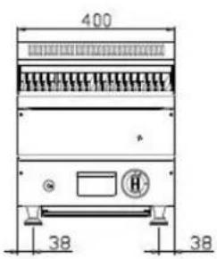
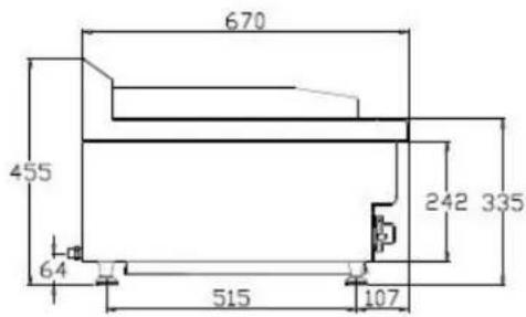
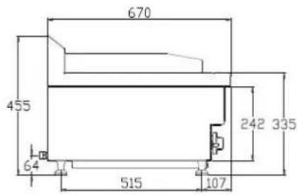
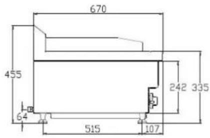
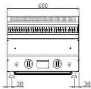
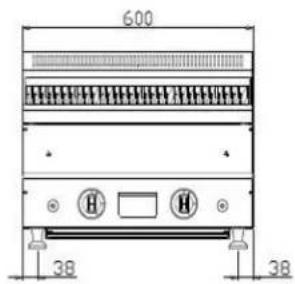
| Dimensions (L x D x H) | 57 x 60 x 46 cm |
| Weight | 54.8 kg |
| Material | Stainless steel |
| Number of burners | 2 |
| Total power | 14.4 kW (2 x 7.2 kW) |
| Gas type | Butane, Propane, G20 (adaptable) |
| Input pressure | 28-30 / 37 / 50 / 20 mbar depending on gas |
| Gas consumption | Butane: 1047 g/h, Propane: 1028 g/h |
| Ignition | Piezoelectric with ignition button |
| Safety | Flame failure protection device (thermocouple) |
| Usage | Professional (restaurants, hotels, caterers) |
| Standards | EN 203-1:2014, EN 203-2-10 |
| Cleaning | Removable grid, wash with neutral detergent, do not spray water on the body |
| Maintenance | Daily inspection, leak check with soapy water |
| Repairability | Spare parts available (nozzles, thermocouple, valve, etc.) |
| Included accessories | Lava stone, cooking grid |
Frequently Asked Questions - RC-GLRG600 Royal Catering
User questions about RC-GLRG600 Royal Catering
0 question about this device. Answer the ones you know or ask your own.
Ask a new question about this device
Download the instructions for your Gas grill in PDF format for free! Find your manual RC-GLRG600 - Royal Catering and take your electronic device back in hand. On this page are published all the documents necessary for the use of your device. RC-GLRG600 by Royal Catering.
USER MANUAL RC-GLRG600 Royal Catering
natural_image
Abstract white line drawing of a stylized mythical creature on a dark blue background (no text or symbols)| DE | Produktname | Lavasteingrill Gas |
| EN | Product name | Gas Lava Grill |
| PL | Nazwa produktu | Grill gazowy lawowy |
| CZ | Název výrobku | Plynový lávový gril |
| FR | Nom du produit | Grill à gaz avec pierres de lave |
| IT | Nome del prodotto | Grill a gas con pietre laviche |
| ES | Nombre del producto | Parrilla de gas con lava |
| HU | Termék neve | Gáz-láva grill |
| DA | Produktnavn | Gas-lavagrill |
| FI | Tuotteen nimi | Kaasulava-grilli |
| NL | Productnaam | Gas-lavagrill |
| NO | Produktnavn | Gass-lavagrill |
| SE | Produktnamn | Gasol-lavagris |
| PT | Nome do produto | Grelhador a gás com lava |
| SK | Názov produktu | Plynový lávový gril |
| BG | Име на продукта | Газова лава скара |
| EL | Όνομα προϊόντος | Γκριλ αερίου με λάβα |
| HR | Naziv proizvoda | Plinski lava roštilj |
| LT | Produkto pavadinimas | Dujinis lavos grilis |
| RO | Numele produsului | Grătar cu lavă pe gaz |
| SL | Ime izdelka | Plinski lava žar |
| DE Modell | EN Product model | PL Model produktu | CZ Model výrobku | FR Modèle | IT Modello | ES Modelo | HU Modell | DA Model | FI Tuotteen malli | NL Productmodel | NO Produktmodell | SE Produktmodell | PT Modelo do produto | SK Model | BG Модел на продукт | EL Movtėlo προϊόντος | HR Model proizvoda | LT: Gaminio modelis | RO: Model de produs | SL: Model izdelka | RC-GLRG400RC-GLRG600 | |
| DE Hersteller | EN Manufacturer | PL Producent | CZ Výrobce | FR Fabricant | IT Produttore | ES Fabricante | HU Termelő | DA Producent | FI Valmistaja | NL Producent | NO Produsent | SE Tillverkare | PT Fabricante | SK Výrobca | BG Производител | EL Κατασκευαστής | HR Proizvođač | LT Gamintojas | RO Producător | SL Proizvajalec | expondo Polska sp. z o.o. sp. k. | |
| DE Anschrift des Herstellers | EN Manufacturer Address | PL Adres producenta | CZ Adresa výrobce | FR Adresse du fabricant | IT Indirizzo del produttore | ES Dirección del fabricante | HU A gyártó címe | DA Producentens adresse | FI Valmistajan osoite | NL Adres producent | NO Produsentens adresse | SE Tillverkarens adress | PT Endereço do fabricante | SK Adresa výrobcu | BG Адрес на производителя | EL: Διεύθυνση κατασκευαστή | HR Adresa proizvođača | LT Gamintojo adresas | RO Adresa producătorului | SL Naslov proizvajalca | ul. Nowy Kisielin – Innowacyjna 7, 66-002 Zielona Góra | Poland, EU | |

natural_image
Line drawing of a portable electric grill with cooling fins and control knobs (no text or symbols)Wichtige Hinweise:
natural_image
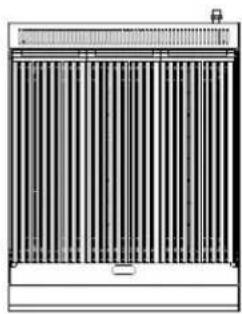
Front view of a vertical heat exchanger or radiator unit with cooling fins and top outlet (no text or symbols visible)RC-GLRG600


natural_image
Pure electrical circuit lines without any symbolsnatural_image
Technical line drawing of a mechanical device with labeled components A and B (no text or symbols beyond labels)This User Manual has been translated for your convenience using machine translation. Reasonable efforts have been made to provide an accurate translation; however, no automated translation is perfect nor is it intended to replace human translators. The official User Manual is the English version. Any discrepancies or differences created in the translation are not binding and have no legal effect for compliance or enforcement purposes. If any questions arise related to the accuracy of the information contained in the User Manual, please refer to the English version of those contents which is the official version.
| Parameter description | Parameter value | |
| Product name | Gas Lava Grill | |
| Model | RC-GLRG400 | RC-GLRG600 |
| Dimensions [width x depth x height cm] | 67.3 x 40 x 45.5 | 57 x 60 x 46 |
| Weight [kg] | 38 | 54.8 |
| Product name: | Gas Lava Grill | CE 1336PIN1008CT3230 | ||
| Model: | RC-GLRG600 | |||
| Appliance Category | I3+(28-30/37) | I3B/P(50) | I2H, I2E | |
| Gas Type: | Butane Propane | Butane, propane and their mixtures | G20 | |
| Inlet Pressure (mbar): | 28-30 | 37 | 50 | 20 |
| Injector Size (mm) | 1.3 | 1.1 | 2.0 | |
| Heat Input (kW) | Main Burners: 7.2 x 2 | |||
| Destination Country: | BE, CH, CY, CZ, ES, FR, GB, GR, IE, IT, LT, LU, LV, PT, SI, SK, TR | AT, CH, CZ, DE, LU, SK | I2H : AT, BG, CH, CY, CZ, DK, EE, ES, FI, FR, GB, GR, HU, IE, IT, LT, LV, NO, PT, RO, SE, SI, SKI2E : DE, LU, PL, RO | |
| Gas Consumption (g/h) | Butane: 1047, Propane: 1028 N/A | |||
| Complied Standard: | EN 203-1:2014 Gas Heated Catering Equipment – Part 1: General Safety Rules EN 203-2-10 Gas Heated Catering Equipment – Part 2-10: Specific requirements-Chargrills | |||
| This appliance shall be installed in conformity with the current regulation and used only in a well-ventilated location. Consult the instructions before installing and using this appliance. | ||||
| Model: | RC-GLRG400 | |||
| Appliance Category | I3+(28-30/37) | I3B/P(50) | I2H, I2E | |
| Gas Type: | Butane Propane | Butane, propane and their mixtures | G20 | |
| Inlet Pressure (mbar): | 28-30 | 37 | 50 | 20 |
| Injector Size (mm) | 1.3 | 1.1 | 2.0 | |
| Heat Input (kW) | Main Burners: 7.2 | |||
| Destination Country: | BE, CH, CY, CZ, ES, FR, GB, GR, IE, IT, LT, LU, LV, PT, SI, SK, TR | AT, CH, CZ, DE, LU, SK | I2H : AT, BG, CH, CY, CZ, DK, EE, ES, FI, FR, GB, GR, HU, IE, IT, LT, LV, NO, PT, RO, SE, SI, SKI2E : DE, LU, PL, RO | |
| Gas Consumption (g/h) | Butane: 523, Propane: 514 | N/A | ||
| Complied Standard: | EN 203-1:2014 Gas Heated Catering Equipment – Part 1: General Safety Rules EN 203-2-10 Gas Heated Catering Equipment – Part 2-10: Specific requirements-Chargrills | |||
| This appliance shall be installed in conformity with the current regulation and used only in a well-ventilated location. Consult the instructions before installing and using this appliance. | ||||
natural_image
Line drawing of a gas grater with cooling fins and control knobs (no text or symbols)Important Notes:
- Please read this instruction manual carefully before using the product.
- Keep this manual in a safe place for future reference.
Warning:
- These instructions are only valid if the country code appears on the appliance. If the code does not appear, refer to the technical instructions for adapting the appliance to the local conditions.
- Any modification, incorrect installation, adjustment, repair, or maintenance may result in property damage or injury. All adjustments or repairs must be conducted by trained professionals.
- For your safety, do not store or use flammable or explosive gases, liquids, or items near this product.
- The device should not be used by individuals (including children) who are physically, perceptually, or mentally impaired, or those lacking experience or knowledge unless supervised or instructed on its safe use.
- Please supervise children to ensure their safety.
- Keep this manual for future reference. If the device is to be used by a third party, ensure they also have access to this manual and adhere to all safety guidelines.
- If the appliance is placed near walls, partitions, or kitchen equipment made of combustible materials, ensure they are protected with non-combustible insulation and comply with fire safety regulations.
- The gas equipment must be installed in a well-ventilated area with proper exhaust systems to ensure safe operation.
- Do not modify the necessary air intakes and smoke vents for combustion to avoid safety hazards.
- The equipment is only suitable for use with a low-pressure gas regulator. Using a high or medium-pressure regulator may cause property damage or safety incidents.
- If you smell gas, avoid any source of ignition, do not use any electrical switches, and do not use any telephone in the vicinity. Close the main gas valve and contact professional maintenance services.
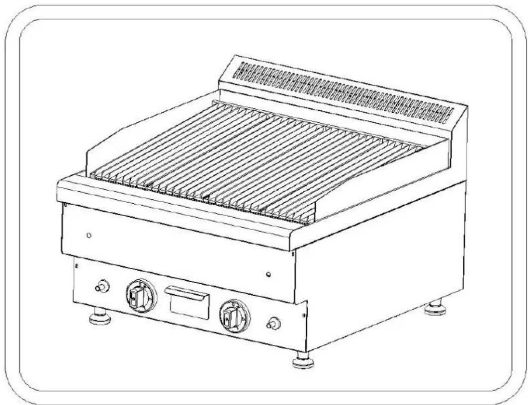
1. Product Functions & Introduction:
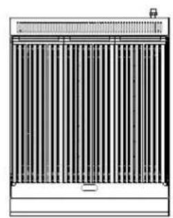
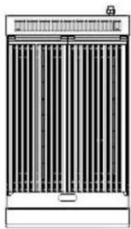
The lava stone grill is a high-quality stainless-steel appliance which stands out for its professional features, intuitive operation, durability, and easy maintenance. It includes a high-efficiency European-style burner, an ignition switch from a reputable manufacturer, a flame-out protection device, and a piezoelectric ceramic ignition system. This grill is ideal for use in hotels, supermarkets, restaurants, fast food outlets, and the catering industry.
2. Structural Sketch:
RC-GLRG400RC

natural_image
Front view of a vertical heat exchanger or radiator unit with cooling fins and top panel (no text or symbols visible)RC-GLRG600


natural_image
Pure electrical circuit lines without any symbols3. Basic Parameters:
List of nozzles
| GasModel | Nozzle hole diameter |
| I3B/P(50) φ1.1mm | |
| I3+(28-30/37) | φ1.3mm |
| I2H(20) φ2.0mm | |
| I2E(20) φ2.0mm |
4. Installation Notes
4.1 Installation Before Use
- For natural gas or liquefied petroleum gas, ensure that the correct type of gas is used as specified. Different gas pressures require different nozzles (see above for details) which must be purchased separately. If the gas source is converted, the nameplate must be updated to specify the corresponding gas source.
- Ensure the feet of the product are installed correctly before use (see image below).
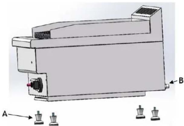
natural_image
Technical line drawing of a mechanical device with labeled components A and B (no text or symbols beyond labels)A. Feet
B. 1/2 BSPT joint
• To connect the inlet pipe, attach the 1/2 BSPT joint on the rear of the unit to the valve body outlet of the air source using a metal pipe or a PVC hose. The PVC hose should not exceed 1.5 meters in length to avoid pressure loss due to excessive hose length. Regularly inspect the PVC hose, and if it shows signs of hardening, replace it promptly. It is recommended to replace the PVC hose every two years. The gas cylinder used should not exceed 320mm in diameter and 680mm in height, with a maximum filling weight of 14.9kg or less.
• The pressure test point is located at the rear intake pipe.
- The regulating valve is pre-set at the factory. If changing the nozzle, reapply sealant and install it properly.
- Remove all protective film before using the equipment.
4.2 Nozzle Replacement Installation
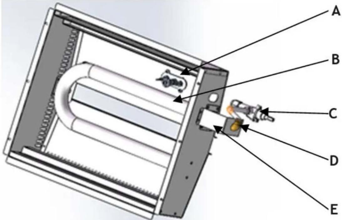
A: Igniter B: Burner C: Intake valve D: Nozzle E: Nozzle fixing pieces
To replace the nozzle, first remove the copper nut with a wrench, then use a Phillips screwdriver to remove the nozzle holder. Replace the old nozzle with a new one, then reassemble the nozzle holder and tighten the copper nut. After replacement, ensure there are no leaks before using the product again.

NOTE! Gas nozzles can be replaced by a qualified technician having the appropriate gas
5. Precautions
5.1 Transport and Storage
During transportation, handle the grill with care. Do not invert it. Store packaged stoves in a well-ventilated, non-corrosive environment. If temporary storage is required, protect the equipment from rain.
5.2 Installation Precautions
• Installation must be performed by professionals.
- Ensure compliance with gas safety regulations during installation.
• Install the equipment separately or in combination with other equipment within the specified range.
- This device is not suitable for embedded installations. Doing so could cause severe hypoxia conditions and the dangerous or even fatal excess emission of combustion products.
- Consider the weight of the device when installing and place it on the ground or a stable table.
- Do not install the grill on flammable surfaces. If placed on a countertop, the countertop material must be fire-resistant.
- It is recommended to install the equipment in a well-ventilated area or under an extractor hood. Maintain a distance of at least 150 mm from walls made of flammable materials. If a safe distance cannot be ensured, use protective measures like refractory materials to maintain the wall temperature within the safety range.
- Remove the plastic film from the device before installation.
- Ensure the equipment is stable, level, and does not shake during use.
- Only use gases compatible with the equipment and use low-pressure regulators only.
• Install a shut-off valve upstream of the equipment, and ensure it is easily accessible. - Verify that the gas type matches the equipment's specifications before use.
- Connect all pipes securely using appropriate metal connections to prevent leaks.
- If the pipeline pressure deviates by more than 15% from the equipment's rated pressure, use a pressure adjuster.
- Test for leaks at all pipe connections using soapy water or test equipment—never use an open flame.
- Check the gas supply pressure after installation.
5.3 Special Attention
- Installation, initial use, and maintenance should be conducted by professionals or certified personnel.
- This product is for commercial use only and must be operated by trained personnel.
- Ensure the equipment's integrity upon removing the packaging. If in doubt, do not use the equipment and consult a professional.
- The first ignition may take longer due to air in the newly installed pipeline. Turn off the ignition switch and wait 3 to 5 minutes before trying again.
- Do not use gases that are not compatible with the equipment and avoid using high or medium-pressure regulators.
- Turn off the equipment when not in use or when the operator is absent.
- The equipment is designed for commercial purposes only, and any other use may cause danger.
- The grill is designed specifically for cooking various types of meat and food. It should not be used for any other purpose.
- Do not use the grill when it is shaking or tilted.
- Do not disassemble or modify the equipment, as this could lead to serious accidents.
- Avoid hitting or placing heavy objects on the equipment, as improper handling may cause damage or danger.
- Ensure the gas heater exhaust outlet is clear of obstructions to prevent health hazards.
- High temperatures can cause burns. Avoid direct contact with the grill's surfaces during and after operation.
- Do not use sharp objects on the control panel and avoid using jet water for cleaning to prevent damage to electrical components.
- Regularly clean the steel surfaces to prevent oxidation and chemical damage.
- Proper installation, professional operation, and regular maintenance ensure optimal performance and extend the grill's service life.
6. Instructions for Use
Before grilling food, preheat the lava rock and grill for at least half an hour. The lava rock and grill store heat for improved cooking.
6.1 Ignition and Flameout
- Push the knob and rotate it counterclockwise.
-
Press the red ignition button until you hear a 'click,' then release it and check if the flame has ignited through the observation hole. If not, continue pressing until the flame ignites.
-
After the burner ignites, keep pressing the knob for 7 to 10 seconds, then release it.
-
If the flame extinguishes within one minute, turn the knob to the "●" position, then wait 3 to 5 minutes, and repeat the ignition process.
-
To adjust the flame, rotate the knob counterclockwise up to 90^ . This is maximum heat. Beyond this point, the flame will gradually decrease.
-
After use, rotate the furnace switch clockwise and close the regulating valve on the gas cylinder.
7. Daily Inspection
Daily inspections are crucial for preventing serious accidents. If you detect the smell of gas or suspect a malfunction, stop using the equipment immediately. Inspect the equipment before and after use every day.
Before Use:
• Is the machine tilted?
• Is the control panel damaged?
During Use:
• Is there an unusual smell or odor?
- Are there any vibrations?
• Is the burner flame normal?
• Is the thermal power normal?
8. Cleanliness and Maintenance
- Clean the grate before use by removing the oblique grate, brushing off limescale with a nylon brush, cleaning with a neutral detergent and water, and wiping with a cloth.
- Do not spray the furnace body with water directly and avoid using corrosive substances for cleaning.
- Do not modify the ventilation settings necessary for combustion.
- Cut off the gas source if the device is not in use.
- If storing the device for a long period, clean the surface with a cloth dipped in gasoline and store in a well-ventilated area.
- Conduct comprehensive inspections at least once a year with the help of professionals.
- Avoid touching the heating plate by hand when the machine is in use to prevent burns.
- Close the gas supply valve when the machine is not in use to avoid accidents.
-
If the machine malfunctions, do not attempt to repair it yourself. Contact the company's maintenance department or a dealer.
-
Fault Analysis and Elimination
| Fault phenomenon | Reason | Method of exclusion |
| Fire does not ignite | Ignition system installation or connection is incorrect.Igniter plug or plug wire is damaged.Low pressure in gas pipe.Nozzle clogging.Thermocouple loosening.Thermocouple damage.Faulty gas control valve. | Please reinstall it correctly.Replace the corresponding spare parts.Adjusting pressure relief valve.Unblocking nozzles.Tightening thermocouple.Replacement thermocouple.Replacement of gas control valve. |
| Fire ignites, but flame is weak | Low pressure in gas pipeMain fire nozzle cloggingFault of gas control valve | Adjusting pressure relief valve.Unblocking nozzles.Replacement of gas control valve. |
| Hissing or popping sounds when gas source is closed | Nozzle size is not compatible with the gas source.Gas source pressure is low.Insufficient gas flow through nozzle. | Adjust the diameter of the nozzle.Adjust the pressure relief valve.Increase pipe diameter for adequate gas flow. |
| Red fire or black smoke | Nozzle size is not compatible with the gas source.The gas in the cylinder is almost exhausted.Gas source composition fluctuates during peak usage. | Adjust the diameter of the nozzle.Change the gas sourceAdjust the flow with the small valve during peak usage, and increase the valve flow afterward. |
Note: If any failures occur, stop using the equipment immediately and contact professional technicians. Safety first! Maintenance must be carried out only after switching off the power and gas source.

natural_image
Line drawing of a portable electric grill with cooling fins and control knobs (no text or symbols)Ważne uwagi:
natural_image
Front view of a vertical heat exchanger or radiator unit with cooling fins and top outlet (no text or symbols visible)RC-GLRG600


natural_image
Pure electrical circuit lines without any symbolsnatural_image
Technical line drawing of a mechanical device with labeled components A and B (no text or symbols beyond labels)natural_image
Line drawing of a gas grater with cooling fins and control knobs (no text or symbols)Důležité poznámky:
natural_image
Front view of a vertical industrial fan or radiator unit with heat sinks and a top-mounted fan (no text or symbols visible)RC-GLRG600


natural_image
Pure electrical circuit lines without any symbolsnatural_image
Technical line drawing of a mechanical device with labeled components A and B (no text or symbols beyond labels)natural_image
Line drawing of a gas grater with cooling fins and control knobs (no text or symbols)natural_image
Front view of a vertical heat exchanger or radiator unit with cooling fins and top outlet (no text or symbols visible)RC-GLRG600


natural_image
Pure electrical circuit lines without any symbolsnatural_image
Technical line drawing of a mechanical device with labeled components A and B (no text or symbols beyond labels)A. Pieds
B. Raccord 1/2 BSPT
natural_image
Line drawing of a gas grater with cooling fins and control knobs (no text or symbols)Note importanti:
natural_image
Front view of a vertical heat exchanger or radiator unit with cooling fins and a top-mounted fan (no text or symbols visible)Modello RC-GLRG600


natural_image
Pure electrical circuit lines without any symbolsnatural_image
Technical line drawing of a mechanical device with labeled components A and B (no text or symbols beyond labels)A. Piedini
B. Giunto 1/2 BSPT
natural_image
Line drawing of a gas grater with cooling fins and control knobs (no text or symbols)Notas importantes:
natural_image
Front view of a vertical heat exchanger or radiator unit with cooling fins and top panel (no text or symbols visible)RC-GLRG600


natural_image
Pure electrical circuit lines without any symbolsnatural_image
Technical line drawing of a mechanical device with labeled components A and B (no text or symbols beyond labels)natural_image
Line drawing of a stainless steel grater with cooling fins and control knobs (no text or symbols)natural_image
Front view of a rectangular industrial fan or radiator unit with vertical slats and a top panel (no text or symbols visible)RC-GLRG600


natural_image
Pure electrical circuit lines without any symbolsnatural_image
Technical line drawing of a mechanical device with labeled components A and B (no text or symbols beyond labels)natural_image
Line drawing of a gas grater with cooling fins and control knobs (no text or symbols)natural_image
Front view of a vertical heat exchanger or radiator unit with cooling fins and top panel (no text or symbols visible)RC-GLRG600


natural_image
Pure electrical circuit lines without any symbolsnatural_image
Technical line drawing of a mechanical device with labeled components A and B (no text or symbols beyond labels)A. Fødder
B. 1/2 BSPT-led
natural_image
Line drawing of a gas grater with cooling fins and control knobs (no text or symbols)natural_image
Front view of a vertical heat exchanger or radiator unit with cooling fins and top panel (no text or symbols visible)RC-GLRG600


natural_image
Pure electrical circuit lines without any symbols3. Perusparametrit:
natural_image
Technical line drawing of a mechanical device with labeled components A and B (no text or symbols beyond labels)A. Jalat
B. 1/2 BSPT-nivel
natural_image
Line drawing of a gas grater with cooling fins and control knobs (no text or symbols)2. Structurele schets:
RC-GLRG400RC


natural_image
Front view of a vertical heat exchanger or radiator unit with cooling fins and top panel (no text or symbols visible)RC-GLRG600


natural_image
Pure electrical circuit lines without any symbols3. Basisparameters:
Lijst met sproeiers
natural_image
Technical line drawing of a mechanical device with labeled components A and B (no text or symbols beyond labels)A. Poten
B. 1/2 BSPT-verbinding
natural_image
Line drawing of a gas grater with cooling fins and control knobs (no text or symbols)Viktige merknader:
- Les denne bruksanvisningen nøye før du bruker produktet.
- Oppbevar denne håndboken på et trygt sted for fremtidig referanse.
Advarsel:
natural_image
Front view of a vertical heat exchanger or radiator unit with cooling fins and top panel (no text or symbols visible)RC-GLRG600


natural_image
Pure electrical circuit lines without any symbolsnatural_image
Technical line drawing of a mechanical device with labeled components A and B (no text or symbols beyond labels)A. Bein
B. 1/2 BSPT skjøt
A: Tenner B: Brenner C: Inntaksventil D: Dyse E: Dysefestestykker
natural_image
Line drawing of a portable electric grill with cooling fins and control knobs (no text or symbols)natural_image
Front view of a rectangular industrial or thermal unit with vertical slats and a top panel (no visible text or symbols)RC-GLRG600


natural_image
Pure electrical circuit lines without any symbolsnatural_image
Technical line drawing of a mechanical device with labeled components A and B (no text or symbols beyond labels)A. Fötter
B. 1/2 BSPT-fog
natural_image
Line drawing of a gas grater with cooling fins and control knobs (no text or symbols)Notas importantes:
natural_image
Front view of a vertical industrial fan or radiator unit with heat sinks and a small top component (no text or symbols visible)RC-GLRG600


natural_image
Pure electrical circuit lines without any symbolsnatural_image
Technical line drawing of a mechanical device with labeled components A and B (no text or symbols beyond labels)A. Pernas
B. Junta 1/2 BSPT
natural_image
Line drawing of a portable electric grill with cooling fins and control knobs (no text or symbols)Dôležité poznámky:
natural_image
Front view of a vertical industrial fan or radiator unit with no visible text or symbolsRC-GLRG600


natural_image
Pure electrical circuit lines without any symbolsnatural_image
Technical line drawing of a mechanical device with labeled components A and B (no text or symbols beyond labels)A: Zapal'ovač B: Horák C: Nasávací ventil D: Tryska E: Upevňovacie diely trysky
natural_image
Line drawing of a portable electric grill with cooling fins and control knobs (no text or symbols)Важни бележки:
natural_image
Front view of a vertical heat exchanger or radiator unit with cooling fins and a top-mounted fan (no text or symbols visible)RC-GLRG600


natural_image
Pure electrical circuit lines without any symbols3. Основни параметри:
Списък на дюзите
natural_image
Technical line drawing of a mechanical device with labeled components A and B (no text or symbols beyond labels)natural_image
Line drawing of a portable electric grill with cooling fins and control knobs (no text or symbols)natural_image
Front view of a rectangular electronic device with vertical bars and a top panel (no visible text or symbols)RC-GLRG600


natural_image
Pure electrical circuit lines without any symbolsnatural_image
Technical line drawing of a mechanical device with labeled components A and B (no text or symbols beyond labels)natural_image
Line drawing of a gas grater with cooling fins and control knobs (no text or symbols)Važne napomene:
natural_image
Front view of a vertical heat exchanger or radiator unit with cooling fins and top panel (no text or symbols visible)RC-GLRG600


natural_image
Pure electrical circuit lines without any symbols3. Osnovni parametri:
Popis mlaznica
| i model\Plinsk | Promjer otvora mlaznice |
| I3B/P(50) φ1,1 mm | |
| I3+(28-30/37) | φ1,3 mm |
| I2H(20) φ2,0 mm | |
| I2E(20) φ2,0 mm |
4. Napomene za instalaciju
natural_image
Technical line drawing of a mechanical device with labeled components A and B (no text or symbols beyond labels)A: Zapaljivač B: Plamenik C: Usisni ventil D: Mlaznica E: Dijelovi za pričvršćivanje mlaznice Za zamjenu mlaznice prvo uklonite bakrenu maticu pomoću ključa, a zatim pomoću križnog odvijača uklonite držač mlaznice. Zamijenite staru mlaznicu novom, zatim ponovno sastavite držač mlaznice i zategnite bakrenu maticu. Nakon zamjene, provjerite da nema curenja prije ponovne uporabe proizvoda.

natural_image
Line drawing of a portable electric grill with cooling fins and control knobs (no text or symbols)Svarbios pastabos:
natural_image
Front view of a rectangular industrial or storage unit with vertical slats and a top panel (no visible text or symbols)RC-GLRG600


natural_image
Pure electrical circuit lines without any symbolsnatural_image
Technical line drawing of a mechanical device with labeled components A and B (no text or symbols beyond labels)A. Pédos
B. 1/2 BSPT jungtis
natural_image
Line drawing of a portable electric grill with cooling fins and control knobs (no text or symbols)Note importante:
natural_image
Front view of a vertical heat exchanger or radiator unit with cooling fins and top panel (no text or symbols visible)RC-GLRG600


natural_image
Pure electrical circuit lines without any symbolsnatural_image
Technical line drawing of a mechanical device with labeled components A and B (no text or symbols beyond labels)A. Picioarele
B. Imbinare 1/2 BSPT
natural_image
Line drawing of a portable electric grill with cooling fins and control knobs (no text or symbols)Pomembne opombe:
natural_image
Front view of a vertical heat exchanger or radiator unit with cooling fins and top panel (no text or symbols visible)RC-GLRG600


natural_image
Pure electrical circuit lines without any symbols3. Osnovni parametri:
Seznam šob
| i model\Plinsk | Premer luknje šobe |
| I3B/P(50) φ1,1 mm | |
| I3+(28-30/37) | φ1,3 mm |
| I2H(20) φ2,0 mm | |
| I2E(20) φ2,0 mm |
natural_image
Technical line drawing of a mechanical device with labeled components A and B (no text or symbols beyond labels)A: Vžigalna naprava B: Gorilnik C: Sesalni ventil D: Šoba E: Pritrdilni deli za šobo Če želite zamenjati šobo, najprej odstranite bakreno matico s ključem, nato pa s križnim izvijačem odstranite nosilec šobe. Zamenjajte staro šobo z novo, nato ponovno sestavite nosilec šobe in privijte bakreno matico. Po zamenjavi se prepričajte, da ne pušča, preden ponovno uporabite izdelek.

For the disposal of the device please consider and act according to the national and local rules and regulations.
CONTACT
expondo Polska sp. z o.o. sp. k.