81780 - Multimeter VOREL - Free user manual and instructions
Find the device manual for free 81780 VOREL in PDF.


User questions about 81780 VOREL
0 question about this device. Answer the ones you know or ask your own.
Ask a new question about this device
Download the instructions for your Multimeter in PDF format for free! Find your manual 81780 - VOREL and take your electronic device back in hand. On this page are published all the documents necessary for the use of your device. 81780 by VOREL.
USER MANUAL 81780 VOREL
text_image
VOREL BY TOYA81780

text_image
C€PL CYFROWY MIERNIK UNIWERSALNY
EN DIGITAL UNIVERSAL MULTIMETER
DE DIGITAL-MULTIMETER
natural_image
Icon of a person reading a book inside a circle (no text or symbols)Przeczytać instrukcję Read the operating instruction Bedienungsanleitung durchgelesen Прочитать инструкцию Прочитать інструкцію Perskaityti instrukciją Jālasa instrukciju Přečtet návod k použití Prečítat' návod k obsluhe Olvasni utasítást Citeşti instructunile Lea la instrucción Lisez la notice d'utilisation Leggere il manuale d'uso Lees de instructies Διαβάστε τις οδηγίες χρήσης Прочетете ръководството Ler as presentes instruções Pročitajte priručnik افراً الدلیل
INSTRUKCJA ORYGINALNA
PL EN DE RU UA LT LV CZ SK HU RO ES FR IT NL GR BG PT HR AR
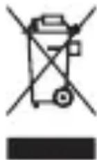
This symbol indicates that waste electrical and electronic equipment (including batteries and storage cells) cannot be disposed of with other types of waste. Waste equipment should be collected and handed over separately to a collection point for recycling and recovery, in order to reduce the amount of waste and the use of natural resources. Uncontrolled release of hazardous components contained in electrical and electronic equipment may pose a risk to human health and have adverse effects for the environment. The household plays an important role in contributing to reuse and recovery, including recycling of waste equipment. For more information about the appropriate recycling methods, contact your local authority or retailer.
PRODUCT CHARACTERISTICS
A digital multimeter is an electronic multifunction device designed to measure various electrical quantities.
Before using the product, please read the entire manual and keep it.
EQUIPMENT
The meter features a plastic housing, a liquid crystal display, and a selector switch for selecting measurement values and ranges. The housing includes measurement sockets. The meter is equipped with test leads terminated with plugs and an adapter for transistor measurements. The meter is supplied without a battery.
Attention! The meter offered is not a measuring instrument within the meaning of the „Measurements Law”.
TECHNICAL DATA
Display: LCD 3,5 digits - maximum displayed result: 2000
Sampling rate: 2 times per second
Overload indication: „1“ symbol displayed
Polarity marking: „-” sign displayed before the measurement result
Battery: 2x AAA (2x 1,5V)
Operating temperature: 0°C ÷ 40°C; relative humidity <80%
Storage temperature: -10^ ÷ +50^ ; relative humidity <85%
External dimensions: 126 x 70 x 26 mm
Weight (without batteries): 92 g
ATTENTION! It is prohibited to measure electrical values that exceed the maximum measuring range of the meter.
| Direct current Direct voltage | |||||
| Range Resolution Accuracy | Range Resolution Accuracy | ||||
| 200 μA 100 | nA | ±(1,8% + 2) | 200 mV 100 | μV ±(0,5% + 3) | |
| 2000 μA | 1 μA | 2000 mV | 1 mV | ±(0,8% + 5)20 mA 10 | |
| 200 mA 100 | μA ±(2,0% + 2) | 200 V | 100 mV | ||
| 10 A | 10 mA | ±(2,0% + 10) | 600 V | 1 V | ±(1,0% + 5) |
EN
| Resistance Alternating voltage (f IN = 40 Hz ÷ 400 Hz) | |||||
| Range Resolution Accuracy | Range Resolution Accuracy | ||||
| 200 Ω 0,1 Ω ±(1,0% + 10) | 200 V 100 mV | ±(2,0% + 10) | |||
| 2000 Ω 1 kΩ | ±(1,0% + 4) | 600 V 1 V | |||
| 20 kΩ 0,01 kΩ | |||||
| 200 kΩ 0,1 kΩ | |||||
| 2000 kΩ 0,001 MΩ | |||||
Accuracy: ± % of reading + weight of the least significant digit
SAFETY INSTRUCTIONS
Do not operate the meter in an atmosphere of excessive humidity, toxic or flammable vapors, or in an explosive atmosphere. Before each use, inspect the condition of the meter and test leads. If any damage is observed, do not proceed. Replace damaged test leads with new, fault-free ones. If in doubt, contact the manufacturer. During measurements, hold the test leads only by the insulated part. Do not touch the measurement points or unused meter sockets with your fingers. Before changing the measured value, disconnect the test leads. Never perform maintenance without ensuring that the test leads have been disconnected from the meter and the meter has been turned off.
PRODUCT SERVICE
Attention! To protect against electric shock, disconnect the test leads and turn off the meter before opening the device housing.
Battery installation and replacement
The multimeter requires batteries, the number and type of which are listed in the technical specifications. Alkaline batteries are recommended. To install the batteries, open the battery cover on the underside of the meter. If the meter is equipped with a rubber cover, remove it from the meter before accessing the batteries. Remove the screw from the battery cover, then open the cover. Connect the batteries according to the terminal markings, close the battery cover, and tighten the screw. If the battery symbol appears on the display, it means the batteries need to be replaced. For accurate measurements, it is recommended to replace the batteries as soon as the battery symbol appears.
EN
Replacing fuses
This product uses fast-blowing fuses. If a fuse is damaged, replace it with a new one with identical electrical parameters. To do this, remove the meter's rear cover. First, open the battery cover, then remove the three screws from the rear cover. Remove the rear cover and, observing safety precautions, replace the fuse with a new one.
Fuse specifications: F500mA/600V for mA socket; F10A/600V for 10A socket.
Turning the meter on and off
Setting the selector to the OFF position turns the meter off. The remaining selector positions turn the meter on and allow you to select the measurement quantity and its range.
Connecting the test leads
If the cable plugs are equipped with covers, remove them before connecting the cables to the sockets. Connect the cables according to the instructions in the manual. Then, remove the test tip covers (if present) and begin measurements.
TAKING MEASUREMENTS
Depending on the current selector position, the display will show four significant digits. When the batteries need replacing, the multimeter will indicate this by displaying a battery symbol. If a „-” sign appears before the measured value, it means the measured value has reverse polarity compared to the meter’s connection. If only the overload symbol „1” appears on the display, it indicates that the measuring range has been exceeded, and in this case, the measuring range should be changed to a higher range.
When measuring unknown quantities, set the meter to the highest measurement range and only change the measurement range to the appropriate range after the initial measurement. Exercise extreme caution when measuring at the highest ranges to avoid electric shock.
WARNING! Do not allow the meter's measurement range to be smaller than the measured value. This may result in damage to the meter and electric shock.
Correct wiring connection is:
- red wire to the socket marked VΩmAhFE or 10A;
- black wire to the socket marked COM.
To achieve the highest possible measurement accuracy, optimal measurement conditions should be ensured. Ambient temperature should be between 18°C and 28°C and relative air humidity should be <75%.
EN
Example of determining accuracy
Accuracy: ± (% of reading + weight of least signifi cant digit)
DC voltage measurement: 1,396 V
Accuracy: ± (0,8% + 5)
Error calculation: 1,396 x 0,8% + 5 x 0,001 = 0,011168 + 0,005 = 0,016168
Measurement result: 1,396 V ± 0,016 V
Voltage measurement
Connect the test leads appropriately: red to the VΩmAhFE jack and black to the COM jack. Set the selector to the voltage measurement position within the specified range: DC (V) or AC (V\~). Connect the test leads parallel to the electrical circuit and read the voltage reading. Never measure a voltage higher than the maximum measurement range. This can damage the meter and result in electric shock. When the lowest measurement range is selected and the test leads are disconnected, a fluctuating reading may be visible on the display. This is normal; to eliminate this, simply short the ends of the test leads together. Do not exceed the maximum voltage values.
Current measurement
Depending on the expected value of the measured current, connect the test leads appropriately: the red one to the VΩmAhFE jack and the black one to the COM or 10A jack. Set the selector to the current measurement position within the specified range (A). The maximum measured current in the VΩmAhFE jack can be 200 mA. To measure a current higher than 200 mA, connect the black test lead to the 10A jack. The maximum measured current in the 10A jack can be 10 A. Currents higher than 200 mA must not be measured for more than 10 seconds, followed by a break of at least 15 minutes before the next measurement. Connect the test leads in series with the electrical circuit being tested, set the current range selector, and read the measurement result. Do not exceed the maximum current values for a given jack.
Resistance measurement
Connect the test leads appropriately: red to the VΩmAhFE jack and black to the COM jack. Set the selector to the resistance measurement position within the specified range (Ω). Touch the test leads to the terminals of the component being measured and read the reading. For values greater than 200 kΩ, the reading may take a few seconds to stabilize; this is normal when measuring higher resistances. Before touching the test leads to the component being measured, the overload symbol appears on the display. Do not measure the resistance of components carrying electrical current or charged capacitors.
EN
Diode test
Connect the test leads appropriately: red to the VΩmAhFE jack and black to the COM jack. Set the selector to the diode test position (diode symbol). Touch the test leads to the diode leads in both the forward and reverse directions. If the diode is good, with the diode connected in the forward direction, you will be able to read the voltage drop across the diode in mV. If connected in the reverse direction, the overload symbol „1“ will appear on the display. Good diodes have low forward resistance and high reverse resistance.
Testing diodes that are carrying electric current is strictly prohibited.
Transistor amplification factor measurement
For transistor measurements, connect the transistor adapter appropriately: the COM / "-" side of the adapter to the COM jack and the INPUT / "+" side to the VΩmAhFE jack. Set the selector to the transistor amplification factor (hFE) measurement position. Depending on your transistor type, connect to the adapter socket marked PNP or NPN, making sure to align the transistor leads with the letters E (emitter), B (base), and C (collector). If the transistor is working properly and connected correctly, read the amplification factor measurement result shown on the display.
Testing transistors connected to an electrical source is strictly prohibited.
MAINTENANCE AND STORAGE
Wipe the meter with a soft cloth. Remove larger dirt with a slightly damp cloth. Do not immerse the meter in water or other liquids. Do not use solvents, caustic agents, or abrasives for cleaning. Keep the meter contacts and test leads clean. Clean the test lead contacts with a cloth lightly moistened with isopropyl alcohol. To clean the meter contacts, turn the meter off and remove the batteries. Invert the meter and shake it gently to remove larger dirt from the meter's connectors. Lightly moisten a cotton swab with isopropyl alcohol and clean each contact. Wait for the alcohol to evaporate, then install the batteries. Store the meter in a dry place in the supplied individual packaging.
DE
PRODUKTA RAKSTUROJUMS
CARACTÉRISTIQUES DU PRODUIT
Le branchement correct est:
Mesure de tension continue: 1,396 V
Précision: ± (0,8% + 5)
Calcul de l'erreur: 1,396 x 0,8% + 5 x 0,001 = 0,011168 + 0,005 = 0,016168