GTC-100L - Wardrobe MSW - Free user manual and instructions
Find the device manual for free GTC-100L MSW in PDF.

| Product Type | Modular Garage Cabinet |
| Brand | MSW |
| Model | GTC-100L |
| Dimensions (W x D x H) | 1960 x 1900 x 490 mm |
| Weight | 118.3 kg |
| Total Maximum Load Capacity | 200 kg |
| Maximum Load Capacity per Shelf | 50 kg |
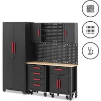
| Kit Contents | 2 wall cabinets, locker, 1 cabinet with 1 drawer, 1 cabinet with 4 drawers, 6 pegboards, support, shelves, casters, handles |
| Intended Use | Storage of tools and workshop equipment, domestic use |
| Material | Steel (estimated) |
| Finish | Paint (estimated) |
| Casters | 2 swivel with brake + 2 fixed (included) |
| Adjustable Feet | Yes, for leveling |
| Doors and Drawers | 1 drawer, 4 drawers, doors on wall cabinets and locker |
| Pegboards | 6 panels for hanging tools |
| Worktop | Included, made of wood |
| Wall Mounting | Recommended to prevent tipping |
| Assembly | Yes, required (tools not included) |
| Maintenance | Clean with a soft non-abrasive cloth, lubricate slides twice a year |
| Storage Conditions | Dry, cool place, away from humidity and sunlight |
| Warranty | According to manufacturer's terms |
Frequently Asked Questions - GTC-100L MSW
User questions about GTC-100L MSW
0 question about this device. Answer the ones you know or ask your own.
Ask a new question about this device
Download the instructions for your Wardrobe in PDF format for free! Find your manual GTC-100L - MSW and take your electronic device back in hand. On this page are published all the documents necessary for the use of your device. GTC-100L by MSW.
USER MANUAL GTC-100L MSW
This User Manual has been translated for your convenience using machine translation. Reasonable efforts have been made to provide an accurate translation; however, no automated translation is perfect nor is it intended to replace human translators. The official User Manual is the English version. Any discrepancies or differences created in the translation are not binding and have no legal effect for compliance or enforcement purposes. If any questions arise related to the accuracy of the information contained in the User Manual, please refer to the English version of those contents which is the official version.
Technical data
| Parameter description Parameter value | ||
| Product name | Garage Cabinet | |
| Model | MSW-GTC-100L | MSW-GTC-200G |
| Load capacity - capacity max. [kg] | 200 | |
| Max. load capacity per shelf [kg] | 50 | |
| Dimensions [width x depth x height; mm] | 1960 x 1900 x 490 | 470 x 1900 x 2070 |
| Weight [kg] | 118.3 | 129.4 |
1. General description
The user manual is designed to assist in the safe and trouble-free use of the device. The product is designed and manufactured in accordance with strict technical guidelines, using state-of-the-art technologies and components. Additionally, it is produced in compliance with the most stringent quality standards.
DO NOT USE THE DEVICE UNLESS YOU HAVE THOROUGHLY READ AND UNDERSTOOD THIS USER MANUAL.
To increase the product life of the device and to ensure trouble-free operation, use it in accordance with this user manual and regularly perform maintenance tasks. The technical data and specifications in this user manual are up to date. The manufacturer reserves the right to make changes associated with quality improvement. The device is designed to reduce noise emission risks to a minimum, taking into account technological progress and noise reduction opportunities.
Legend


Read instructions before use.
WARNING! or CAUTION! or REMEMBER! Applicable to the given situation. (general warning sign)
ATTENTION! Hand crush hazard!
Only use indoors.

PLEASE NOTE! Drawings in this manual are for illustration purposes only and in some details may differ from the actual product.
2. Usage safety

ATTENTION!
Read all safety warnings and all instructions. Failure to follow the warnings and instructions may result in serious injury or even death.
The terms "device" or "product" are used in the warnings and instructions to refer to:
Garage Cabinet
2.1. Safety in the workplace
a) Make sure the workplace is clean and well lit. A messy or poorly lit workplace may lead to accidents. Try to think ahead, observe what is going on and use common sense when working with the device.
b) If you are unsure about whether the product is operating correctly or if you find damage, please contact the manufacturer's service centre.
c) Only the manufacturer's service centre may make repairs to the product. Do not attempt to make repairs yourself!
d) Regularly inspect the condition of the safety labels. If the labels are illegible, they must be replaced.
e) Please keep this manual available for future reference. If this device is passed on to a third party, the manual must be passed on with it.
f) Keep packaging elements and small assembly parts in a place not available to children.
g) If this device is used together with another equipment, the remaining instructions for use shall also be followed.

Remember! When using the device, protect children and other bystanders.
2.2. Personal safety
a) The device is not designed to be handled by persons (including children) with limited mental and sensory functions or persons lacking relevant experience and/or knowledge unless they are supervised by a person responsible for their safety or they have received instruction on how to operate the device.
b) When working with the device, use common sense and stay alert. Temporary loss of concentration while using the device may lead to serious injuries.
c) The device is not a toy. Children must be supervised to ensure that they do not play with the device.
2.3. Safe device use
a) Do not overload the device. Use the appropriate tools for the given task. A correctly-selected device will perform the task for which it was designed better and in a safer manner.
b) Keep the device in perfect technical condition. Before each use check for general damage, especially check moving components for cracked parts or elements, and for any other conditions which may impact the safe operation of the device. If damage is discovered, hand over the device for repair before use.
c) To ensure the operational integrity of the device, do not remove factory-fitted guards and do not loosen any screws.
d) When transporting and handling the device between the warehouse and the destination, observe the occupational health and safety principles for manual transport operations which apply in the country where the device will be used.
e) Clean the device regularly to prevent stubborn grime from accumulating.
f) It is forbidden to interfere with the structure of the device in order to change its parameters or construction.
g) Do not overload the device.

ATTENTION! Despite the safe design of the device and its protective features, and despite the use of additional elements protecting the operator, there is still a slight risk of accident or injury when using the device. Stay alert and use common sense when using the device.
3. Use guidelines
The product is designed to store equipment, workshop tools and organise the workplace.
The product is intended for home use only.
The user is liable for any damage resulting from unintended use of the device.
3.1. Assembling the device
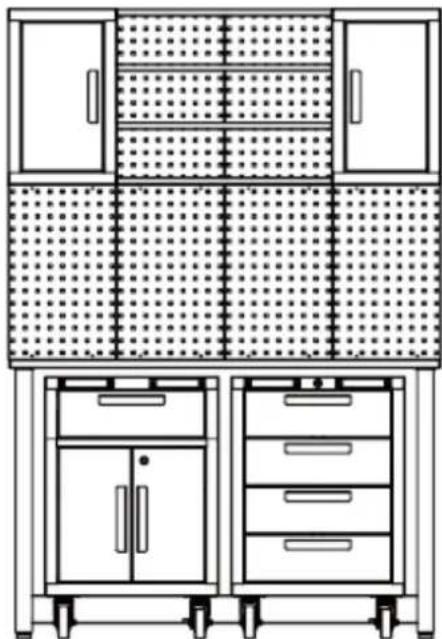
3.1.1. MSW-GTC-100L
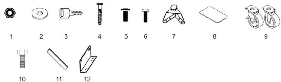
Hardware Included:
| No. | DESCRIPTION | WALLCABINETx2 | LOCKERx1 | 1-DRAWERCABINETx1 | 4-DRAWERR.CABINETx1 | PEGBOARDx6 | BRACKETx1 |
| 1 | M6 Hex Flange Nut | 8 | 4 | 4 | 0 | 0 | 2 |
| 2 | Flat Washer | 4 | 4 | 2 | 0 | 4 | 0 |
| 3 | Key | 0 | 2 | 2 | 2 | 0 | 0 |
| 4 | M5 x 50 HexTapping Bolt | 4 4 2 0 4 0 | |||||
| 5 | M6 x 12 Flat-HeadBolt | 8 16 20 0 0 4 | |||||
| 6 | M5 x 12 Flat-HeadBolt (on the door) | 2 4 6 8 0 0 | |||||
| 7 | AdjustableLevelling Feet | 0 4 4 0 0 0 | |||||
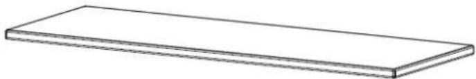
| 8 | Shelf | 0 | 3 | 1 | 0 | 0 | 0 |
| 9 | Casters | 0 | 0 | 0 | 4 | 0 | 0 |
| 10 | M8 x 20 HexFlange Bolt | 0 0 0 16 0 0 | |||||
| 11 | Handle | 1 | 2 | 3 | 4 | 0 | 0 |
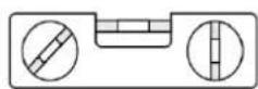
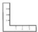
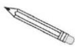
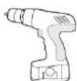
Helpful tools:
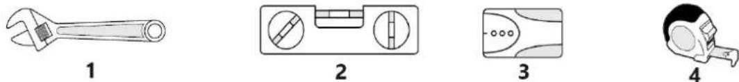

| 1 | Adjustable Wrench | 4 | Measuring Tape | 7 | 6 mm Phillips Screwdriver |
| 2 | Magnetic Leveller | 5 | Setsquare | 8 | 5 mm Slotted Screwdriver |
| 3 | Stud Finder | 6 | Pencil | 9 | Cordless Power Drill |
| Locker x 1 | |
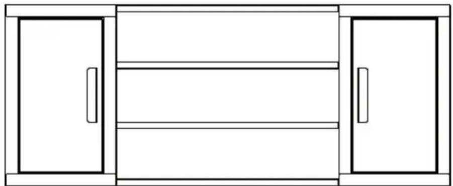
| Wall cabinet x 2 | |
| Shelf to connect the wall cabinets x 4 | |
| 1-drawer cabinet x1 | |
| 4-drawer roller cabinet x1 | |
| workbench x1 | |
| Pegboard x6 |
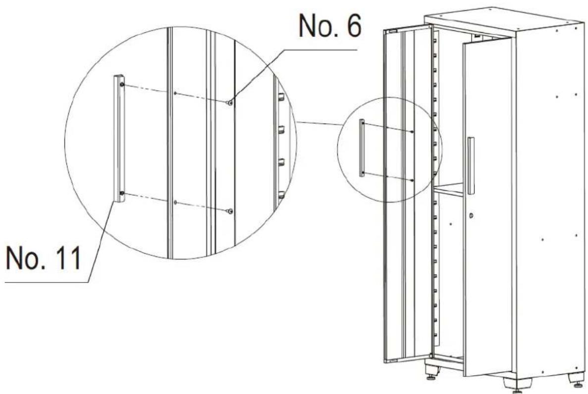
Handles Assembly
Unscrew the bolts on the front of the drawers or the doors using a Phillips screwdriver to remove the handle on the back of it, then attach the handle to the front of the door or the drawer using two M5x12 flat head bolts. Repeat for all the doors and drawers.
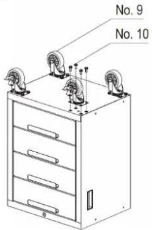
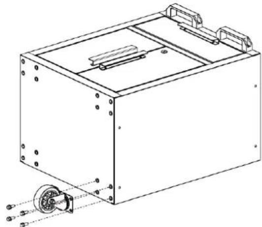
Casters Assembly
- Securely lock all the drawers of the rolling cabinet.
- Lay the rolling cabinet upside down. Use the packaging material for protection.
- Mount the two swivel casters with brake to the front of the rolling cabinet using four M8x20 mm bolts per caster.
- Mount the two regular casters to the other side of the rolling cabinet using four M8x20 mm bolts per caster.
- Tighten all bolts with a wrench.
- Return the rolling cabinet to its upright position.
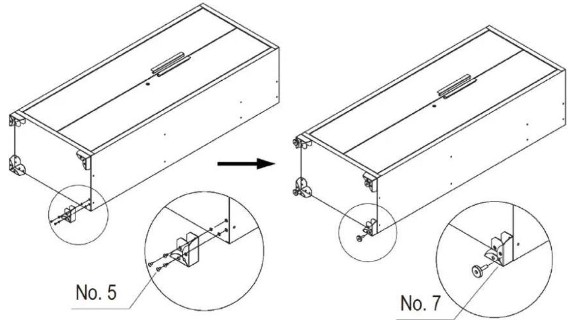
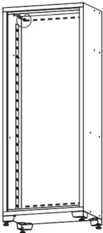
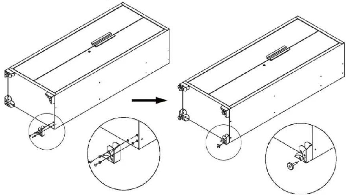
Feet Assembly
Carefully set the locker on its back, then attach the adjustable levelling feet to the locker using sixteen M6x12 flat-head bolts with a Philips screwdriver.
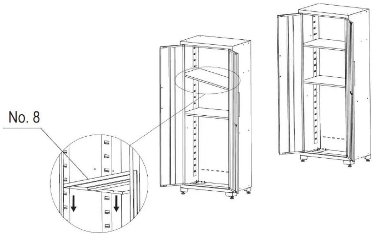
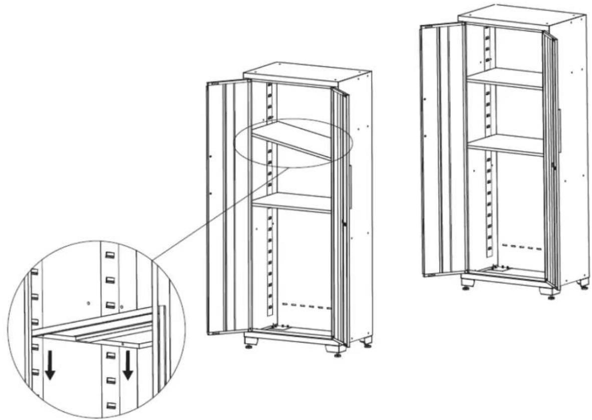
Shelves Assembly
Check the location need, carefully put the shelf into the slot. Please make sure the shelf is stable.
NOTE: A centre shelf must be installed level with the lock on the cabinet door for lock to work.
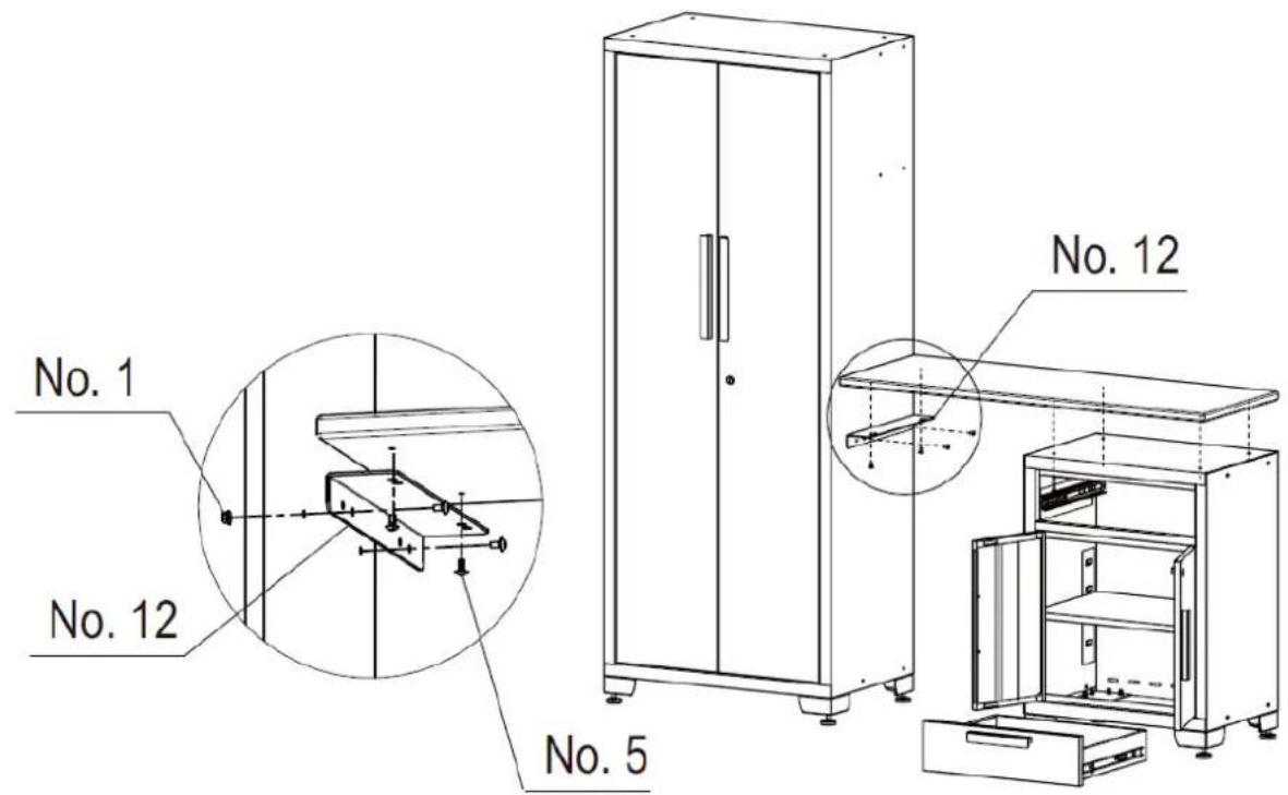
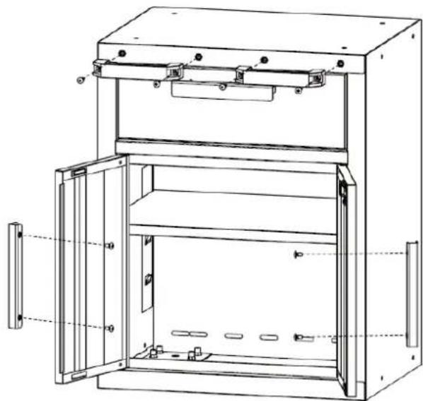
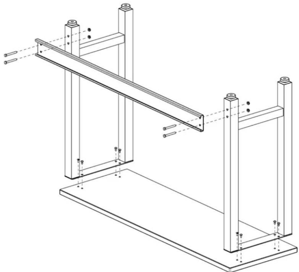
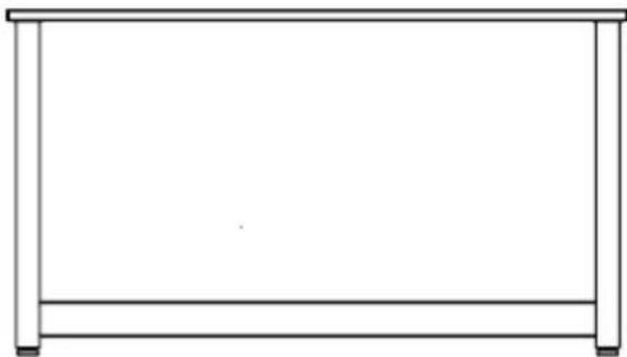
Installing the Worktop
Open the doors or remove the drawers to make sure that you have enough space to install the worktop.
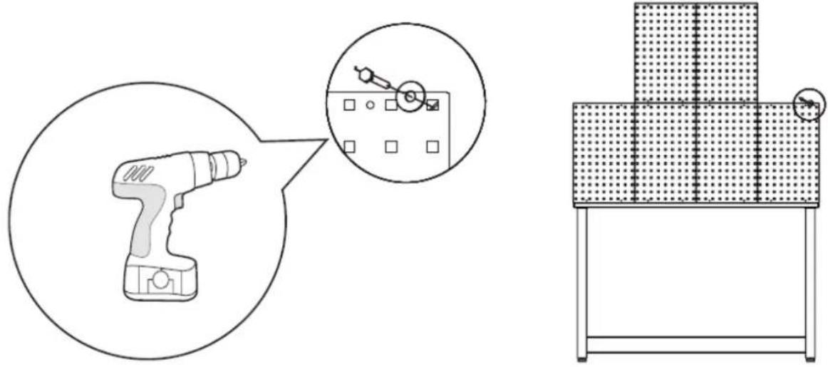
Carefully place the wood worktop on the cabinets and fasten it with screwdriver or cordless power drill and four screws in the parts package of each bottom cabinet. If there is no bottom cabinet on one side, connect the worktop with a bracket to the side of the locker with four screws and two nuts.
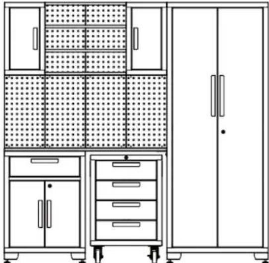
Setup
- Plan the position of the cabinets, position the locker and 1-drawer cabinet.
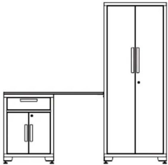
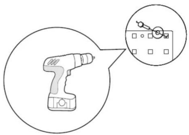
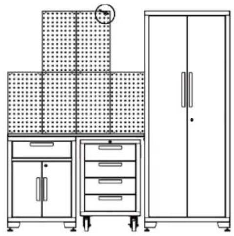
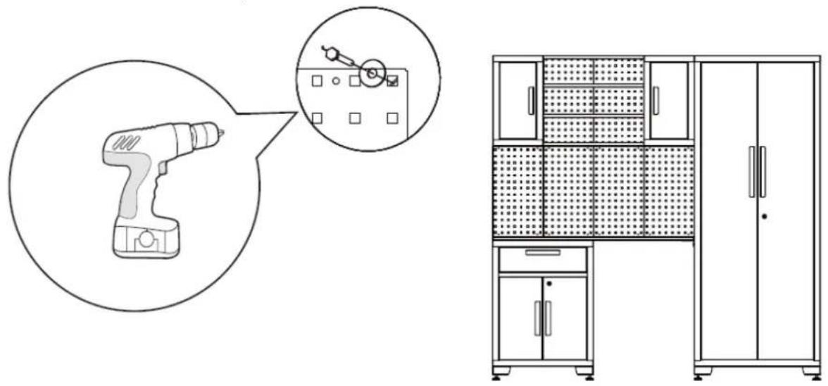
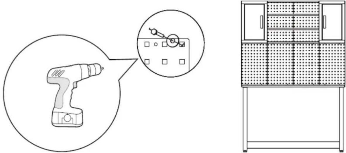
- Align the pegboard and screw them onto the wall.
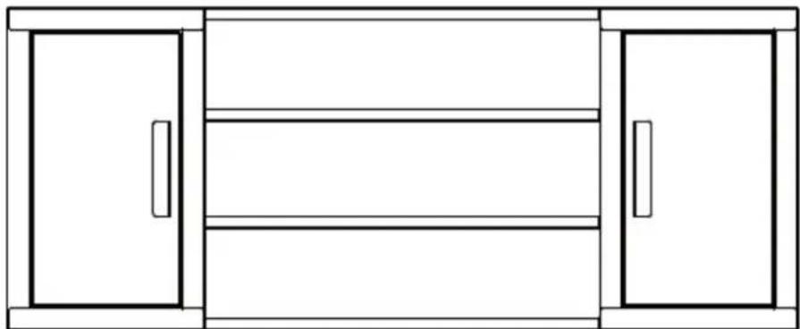
- Connect the two wall cabinets with the shelves.
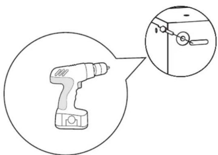
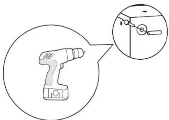
- Open the door of the wall cabinet, connect the wall cabinet assembly to the wall. Two or more persons is recommended for this step.
- Roll the tool cabinet under the workbench. Open the door of the locker and securely attach the locker on the wall to prevent it from tipping.
Fasten all the bolts. The installation of the garage cabinet set is finished.
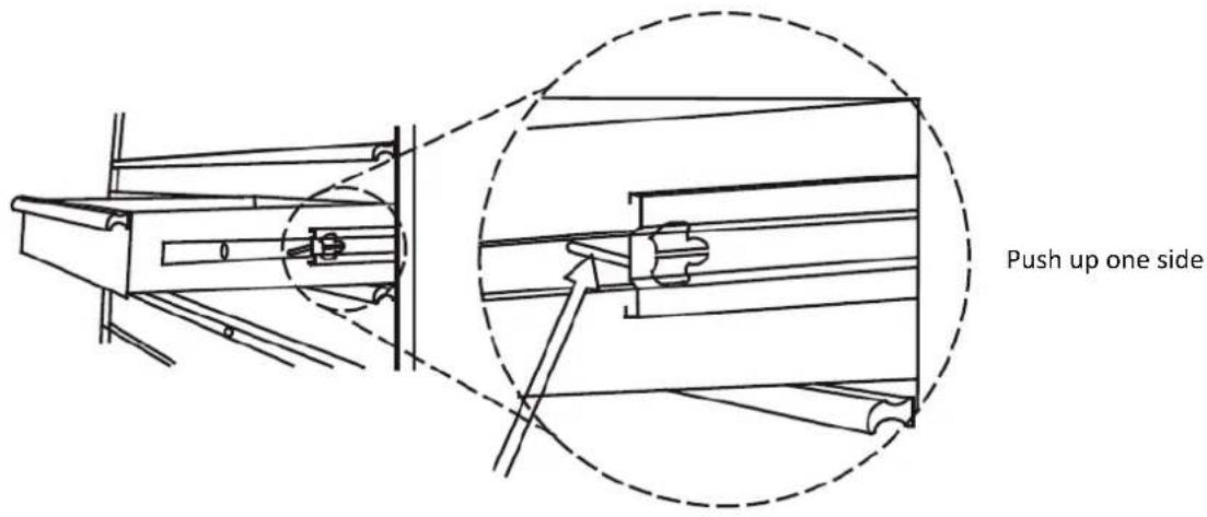
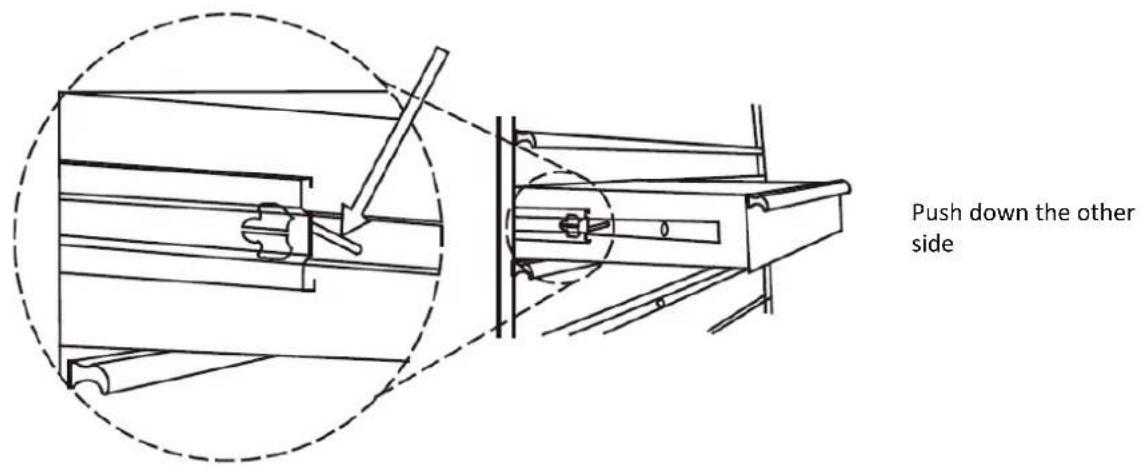
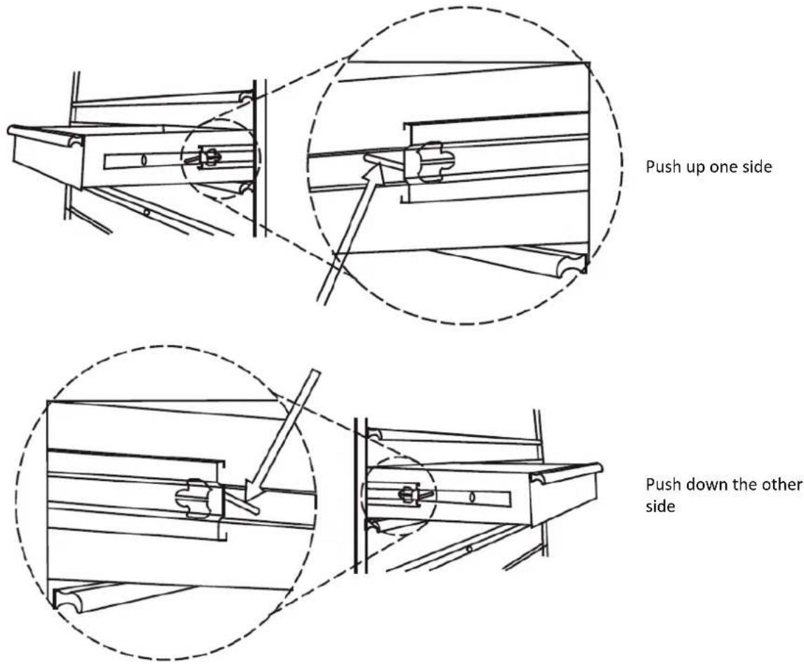
Drawer Removal
Put the drawer out so that it's almost fully extended. Push up on the black release lever on one side, while pulling down on the black release lever on the other side. While holding the levers in the positions as illustrated below, pull the drawer outward until it is released from the drawer slide.
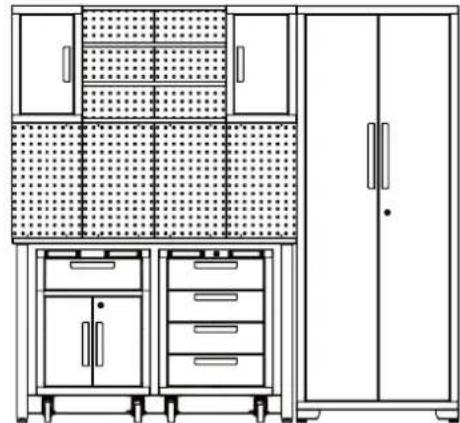
3.1.2. MSW-GTC-200G
Hardware Included
| No. | DESCRIPTION | WALLCABINETx2 | LOCKERx1 | 1-DRAWERR.CABINETx1 | 4-DRAWERR.CABINETx1 | 52INWORKBENCHx1 | PEGBOARDx6 |
| 1 | M6 Hex FlangeNut | 8x2 4 0 | 0 0 0 | ||||
| 2 | Flat Washer | 4x2 | 4 | 0 | 0 | 0 | 4x6 |
| 3 | Key | 0 | 2 | 2 | 2 | 0 | 0 |
| 4 | M5 x 50 HexTapping Bolt | 4x2 4 0 | 0 0 4x6 | ||||
| 5 | M6x 12 Flat-Head Bolt | 8x2 20 | 0 0 0 0 | ||||
| 6 | M5 x 12 Flat-Head Bolt (onthe door) | 2x2 4 6 | 8 0 0 | ||||
| 7 | AdjustableLevelling Feet | 0 4 0 | 0 0 0 | ||||
| 8 | Shelf | 0 | 3 | 1 | 0 | 0 | 0 |
| 9 | Casters | 0 | 0 | 4 | 4 | 0 | 0 |
| 10 | M8 x 20 HexFlange Bolt | 0 0 16 | 16 0 0 | ||||
| 11 | Grab Handle | 0 | 0 | 2 | 2 | 0 | 0 |
| 12 | M8 x 16 Flat-Head Bolt | 0 0 4 | 4 8 0 | ||||
| 13 | M8 x 65 Hex Bolt | 0 | 0 | 0 | 0 | 4 | 0 |
| 14 | M8 Hex FlangeNut | 0 0 0 | 0 4 0 |
Helpful Tools
1
2

3

4
6

7

8
9
| 1 | Adjustable Wrench | 4 | Measuring Tape | 7 | 6 mm Phillips Screwdriver |
| 2 | Magnetic Leveller | 5 | Set Square | 8 | 5 mm Slotted Screwdriver |
| 3 | Stud Finder | 6 | Pencil | 9 | Cordless Power Drill |
| Locker x 1 | |
| Wall cabinet x 2 | |
| Shelf to connect the wall cabinets x 4 | |
| 1-drawer roller cabinet x1 | |
| 4-drawer roller cabinet x1 | |
| workbench x1 | |
| Pegboard x6 |
Installing the Handles
Unscrew the bolts on the front of the drawers or the doors using a Phillips screwdriver to remove the handle on the back of it, then attach the handle to the front of the door or the drawer using two M5x12 flat head bolts. Repeat for all the doors and drawers. Attach the grab handle to the cabinet, align the holes and fix with two M8x16 flat head bolts.
Installing the Casters
Lay the rolling cabinet on soft ground. Use the packaging material for protection. Mount four casters to each cabinet with sixteen M8x20 hex flange bolts. Note: The casters with brakes should be on the front side of the cabinet.
Installing the Feet
Carefully set the locker on its back, then attach the adjustable levelling feet to the locker using sixteen M6x12 flat-head bolts with a Philips screwdriver.
Installing the Shelves
Check the location need, carefully put the shelf into the slot. Please make sure the shelf is stable. NOTE: A centre shelf must be installed level with the lock on the cabinet door for lock to work.
Installing the Workbench
- Lay down the work top on a soft surface, align the holes on the legs with that on the worktop. Use four M8x16 bolts to connecting them together.
- Use four M8x65 hex bolts and four M8 nuts to fasten support to the legs.
- Fasten all the bolts and nuts.
- Stand up the workbench to finish this step.
Setup
- Plan the position of the cabinets, position the workbench.
- Align the pegboard and screw them onto the wall.
- Connect the two wall cabinets with the shelves.
- Open the door of the wall cabinet, connect the wall cabinet assembly to the wall. Two or more persons is recommended for this step.
- Roll the tool cabinet under the workbench.
- Lean the cabinet against the table. Open the door of the locker and securely attach the locker on the wall to prevent it from tipping.
The installation of the garage cabinet set is finished.
DrawerRemoval
Put the drawer out so that it's almost fully extended. Push up on the black release lever on one side, while pulling down on the black release lever on the other side. While holding the levers in the positions as illustrated below, pull the drawer outward until it is released from the drawer slide.
3.2. Cleaning and maintenance
a) Use only non-corrosive cleaners to clean the surface.
b) After cleaning the device, all parts should be dried completely before using it again.
c) Store the unit in a dry, cool place, free from moisture and direct exposure to sunlight.
d) Do not spray the device with a water jet or submerge it in water.
e) The device must be regularly inspected to check its technical efficiency and spot any damage.
f) Use a soft, damp cloth for cleaning.
g) Do not use sharp and/or metal objects for cleaning (e.g. a wire brush or a metal spatula) because they may damage the surface material of the appliance.
h) Do not clean the device with an acidic substance, agents of medical purposes, thinners, fuel, oils or other chemical substances because it may damage the device.
i) Lubricate the slides twice a year with a quality lubricant. This is especially necessary when the temperature drops, which may cause the bearings to be stiff.

Installation de I'etabli
Instalando as prateleiras
For the disposal of the device please consider and act according to the national and local rules and regulations.
CONTACT
expondo Polska sp. z o.o. sp. k.