Phoenix Contact CF 500-230V - Electrical measuring device

CF 500-230V - Electrical measuring device Phoenix Contact - Free user manual and instructions

Find the device manual for free CF 500-230V Phoenix Contact in PDF.

📄 362 pages English EN Download 💬 AI Question 10 questions ⚙️ Specs
Notice Phoenix Contact CF 500-230V - page 27
Pick your language and provide your email: we'll send you a specifically translated version.
Product TypeElectric Crimping Tool
BrandPhoenix Contact
ModelCF 500-230V
Supply Voltage230 V / 50 Hz
Power Consumption160 VA
Maximum Crimping Force10 kN
Crimping Time< 1 s
Dimensions (L x H x D)140 mm x 220 mm x 320 mm
Weight of Base Unit10 kg
Weight of Foot Switch1.2 kg
DisplayResettable 6-digit LCD piece counter
Operating Modes1 step (full crimping) / 2 steps (fixation then crimping)
Operating Temperature Range10 °C to 40 °C
LED IndicatorsReady, Error, Maintenance, Mode 1, Mode 2
SafetyProtective cover with automatic shut-off device
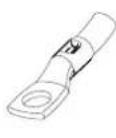
Intended UseCrimping of crimp contacts (ferrules, TWIN, turned contacts, clips, insulated terminals, tubular terminals, etc.)
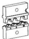
Crimping DieInterchangeable, centering and adjustment possible
Crimping Force AdjustmentSlider from 1 to 5
Die Opening AdjustmentVia buttons with LED indicator (4 LEDs)
Recommended MaintenanceAfter 500,000 crimps by Phoenix Contact
Mains Fuses2 x 1.25 A (type FUSE SB 1.25 A)
Foot Switch ConnectionYes
Available AccessoriesPositioners for clips and flat connectors
Protective CoverSpecific to each crimping die
WarrantyAccording to Phoenix Contact general terms and conditions of sale

Frequently Asked Questions - CF 500-230V Phoenix Contact

How to commission the CF 500?
To commission, place the device on a flat surface, remove the protective cover after disconnecting the mains, install the appropriate crimping die, replace the cover, connect the foot switch and mains, then turn on the switch. The ready LED should light up. Then perform centering and die adjustment.
What to do if the "error" LED lights up?
The error LED may indicate: foot switch released too early (press enter and repeat), incorrect wire gauge (use correct gauge), wrong crimping force setting (increase slider position), or incorrect die adjustment (follow commissioning procedure).
How to adjust the crimping force?
The crimping force is adjusted via the slider (positions 1 to 5). Move the slider to a higher position to increase the force. Perform a test crimp without a contact, then with the appropriate contact. If the error LED flashes, increase by one step until it goes out, then add one additional step to compensate for tolerances.
How to change the crimping die?
First, disconnect the mains connector. Remove the protective cover by unscrewing its screw. Loosen the screws of the upper and lower dies, remove the old dies, place the new ones respecting the position (small section in front, large section at the back), tighten the screws without locking them, then perform centering and adjustment. Replace the appropriate protective cover.
Which types of contacts can be crimped?
The CF 500 can crimp: ferrules (A..., AI...), TWIN ferrules (AI-TWIN), turned contacts (CK...), clips and flat connectors (SCF..., SCM...), insulated terminals (RCI, FCI, C-RCI, C-FCI), terminals (RC, FC) per DIN 46234, and tubular terminals (standard and DIN 46235). Consult the manual for compatible wire gauges.
How to use two-step mode?
Press the Operating mode 2 button. Insert the crimp contact into the die and press the foot switch once to fix the contact. Release, insert the wire, then press a second time to perform the full crimp. The die opens automatically after crimping.
What does the "Maintenance" LED mean?
The Maintenance LED lights up after approximately 500,000 crimps. It indicates that preventive maintenance is recommended. Phoenix Contact advises having this maintenance performed by its services to maintain consistent crimp quality.
How to reset the piece counter?
The piece counter (6-digit LCD display) is reset by pressing the reset button. It retains its value for about a week after power-off. To record the value before resetting, note it down.
Which fuses should be used?
For the CF 500-230V model, use two mains fuses of type FUSE SB 1.25 A (part number 1208801). For the CF 500-120V, they are 2.5 A fuses (part number 1209062). Check and replace defective fuses after disconnecting the device.
Where to find the crimping die part numbers?
The part numbers for crimping dies and associated protective covers are listed in the appendix of the manual. For example: CF 500/DIE AI 6 (1212238) for ferrules 0.25-6 mm², CF 500/COV AI 6 (1212254) for the cover. Refer to the die table on page 19 of the manual.

User questions about CF 500-230V Phoenix Contact

0 question about this device. Answer the ones you know or ask your own.

Ask a new question about this device

The email remains private: it is only used to notify you if someone responds to your question.

No questions yet. Be the first to ask one.

Download the instructions for your Electrical measuring device in PDF format for free! Find your manual CF 500-230V - Phoenix Contact and take your electronic device back in hand. On this page are published all the documents necessary for the use of your device. CF 500-230V by Phoenix Contact.

USER MANUAL CF 500-230V Phoenix Contact

natural_image Hand inserting a black cable into a white electronic device with visible internal components (no text or symbols)

UM IA CF 500 (2888039)

DE Anwenderhandbuch

CF 500-230V

EN User Manual

CF 500-120V
text_image Technical diagram showing labeled components of an electrical device, including a control box, cable, and motor.
text_image Technical diagram of a device with numbered components, likely an electrical or mechanical assembly.

Phoenix Contact CF 500-230V - 1

text_image Technical diagram of a device with numbered parts labeled 6, 7, 8, 9, and 10

Phoenix Contact CF 500-230V - 2

natural_image Technical line drawing of a mechanical clamp or bracket component (no text or symbols)
natural_image Line drawing of a rectangular electronic device with a lid and internal ports (no text or symbols)
Phoenix Contact CF 500-230V - 3

text_image Technical diagram showing a door switch mechanism with labeled parts 1 and 2, including a close-up view of the component.

CF 500 aufstellen

Phoenix Contact CF 500-230V - CF 500 aufstellen - 1

text_image Technical diagram of a refrigerator interior with labeled parts and directional arrows indicating movement or assembly.

Phoenix Contact CF 500-230V - CF 500 aufstellen - 2

text_image Technical diagram showing a device with two labeled parts: one inserted into a box and the other attached to a control panel.

Phoenix Contact CF 500-230V - CF 500 aufstellen - 3

text_image Technical diagram showing labeled components of an electrical device with numbered parts and wiring connections

Crimpgesenk montieren

Phoenix Contact CF 500-230V - Crimpgesenk montieren - 1

text_image Technical diagram of an electrical switch device with numbered components and labeled parts

Phoenix Contact CF 500-230V - Crimpgesenk montieren - 2

text_image Technical diagram showing installation steps of a computer drive with labeled components and cable connections
text_image Technical diagram of an electrical switchgear assembly with numbered components and exploded view

Phoenix Contact CF 500-230V - Crimpgesenk montieren - 3

text_image Technical diagram showing a control panel with labeled components and an exploded view of the device interior.

Phoenix Contact CF 500-230V - Crimpgesenk montieren - 4

natural_image Technical line drawing of a mechanical device with labeled components and an orange panel on the left (no text or symbols present)
text_image Technical diagram of a device with numbered components, showing front and side views of a device casing.

Phoenix Contact CF 500-230V - Crimpgesenk montieren - 5

text_image Technical diagram of a device with numbered components and directional arrows indicating assembly or movement.

Phoenix Contact CF 500-230V - Crimpgesenk montieren - 6

text_image Technical diagram of two electronic devices with labeled components, showing internal wiring and mounting parts.

Crimpkontakt crimpen

text_image Technical diagram of a device with numbered components, showing front and side views of a device casing.

Phoenix Contact CF 500-230V - Crimpkontakt crimpen - 1

text_image Technical diagram showing mechanical assembly with numbered components and directional arrows indicating assembly steps

Phoenix Contact CF 500-230V - Crimpkontakt crimpen - 2

text_image Technical diagram showing labeled mechanical components with numbered parts and directional arrows indicating assembly or assembly.

Phoenix Contact CF 500-230V - Crimpkontakt crimpen - 3

text_image Technical diagram showing two labeled views of a device with internal components, likely illustrating a mechanical or electrical assembly.
natural_image Line drawing of a refrigerator with an open door and internal compartments (no text or symbols)
Phoenix Contact CF 500-230V - Crimpkontakt crimpen - 4

Phoenix Contact CF 500-230V - Crimpkontakt crimpen - 5

text_image Technical diagram showing installation steps of an electronic device with labeled components
text_image Technical diagram showing exploded view of a power connector with labeled parts including socket, plug, and connectors

A Anhang

A 1 Bestelldaten

Elektrocrimper

This user manual is valid for:

Designation Order No.

CF 500-230V 1208348

CF 500-120V 1208351

Please observe the following notes

User group of this manual

The use of products described in this manual is oriented exclusively to qualified electricians or persons instructed by them, who are familiar with applicable standards and other regulations regarding electrical engineering and, in particular, the relevant safety concepts.

Explanation of symbols used and signal words

Phoenix Contact CF 500-230V - Explanation of symbols used and signal words - 1

This is the safety alert symbol. It is used to alert you to potential personal injury hazards. Obey all safety measures that follow this symbol to avoid possible injury or death.

There are three different categories of personal injury that are indicated with a signal word.

DANGER This indicates a hazardous situation which, if not avoided, will result in death or serious injury.

WARNING This indicates a hazardous situation which, if not avoided, could result in death or serious injury.

CAUTION This indicates a hazardous situation which, if not avoided, could result in minor or moderate injury.

Phoenix Contact CF 500-230V - Explanation of symbols used and signal words - 2

This symbol together with the signal word NOTE and the accompanying text alert the reader to a situation which may cause damage or malfunction to the device, hardware/software, or surrounding property.

Phoenix Contact CF 500-230V - Explanation of symbols used and signal words - 3

This symbol and the accompanying text provide the reader with additional information or refer to detailed sources of information.

How to contact us

Internet

Up-to-date information on Phoenix Contact products and our Terms and Conditions can be found on the Internet at: www.phoenixcontact.com

Make sure you always use the latest documentation.

It can be downloaded at:

www.phoenixcontact.net/catalog

Subsidiaries

If there are any problems that cannot be solved using the documentation, please contact your Phoenix Contact subsidiary.

Subsidiary contact information is available at www.phoenixcontact.com

Published by PHOENIX CONTACT GmbH & Co. KG

Flachsmarktstraße 8

32825 Blomberg

GERMANY

Should you have any suggestions or recommendations for improvement of the contents and layout of our manuals, please send your comments to:

tecdoc@phoenixcontact.com

General terms and conditions of use for technical documentation

Phoenix Contact reserves the right to alter, correct, and/or improve the technical documentation and the products described in the technical documentation at its own discretion and without giving prior notice, insofar as this is reasonable for the user. The same applies to any technical changes that serve the purpose of technical progress.

The receipt of technical documentation (in particular user documentation) does not constitute any further duty on the part of Phoenix Contact to furnish information on modifications to products and/or technical documentation. You are responsible to verify the suitability and intended use of the products in your specific application, in particular with regard to observing the applicable standards and regulations. All information made available in the technical data is supplied without any accompanying guarantee, whether expressly mentioned, implied or tacitly assumed.

In general, the provisions of the current standard Terms and Conditions of Phoenix Contact apply exclusively, in particular as concerns any warranty liability.

This manual, including all illustrations contained herein, is copyright protected. Any changes to the contents or the publication of extracts of this document is prohibited.

Phoenix Contact reserves the right to register its own intellectual property rights for the product identifications of Phoenix Contact products that are used here. Registration of such intellectual property rights by third parties is prohibited.

Other product identifications may be afforded legal protection, even where they may not be indicated as such.

Table of contents

1 Basic information ....7

1.1 Intended use....7
1.2 Workplaces 8
1.3 For your safety....8

2 Description of the CF 500 9

2.1 Supplied as standard....9
2.2 Overview of the operating components ....9
2.3 Function of the operating components....10
2.4 Scope of use of the CF 500....10

3 Starting up the CF 500 ....11

3.1 Overview 11
3.2 How to proceed....11

4 Operation 15

4.1 One-step crimping.... 15
4.2 Two-step crimping.... 16

5 Troubleshooting 17

5.1 "Error" LED lights up....17
5.2 CF 500 will not switch on....18

A Appendix....19

A 1 Ordering data .... 19
A 2 Technical data....21

1 Basic information

For safe handling and trouble-free operation of the CF 500, you must be familiar with and observe the safety notes.

1.1 Intended use

Phoenix Contact CF 500-230V - Intended use - 1

WARNING: The CF 500 is intended solely for crimping.

Only crimping dies with suitable cross sections may be used (see "Crimping dies and protective covers" on page 19).

Under no circumstances should solid metal parts or other similar objects be inserted. This damages the crimping die.

Unauthorized conversions that exceed the scope of modification, and changes to the CF 500 are not permitted for safety reasons.

Phoenix Contact CF 500-230V - Intended use - 2

NOTE: Correct usage includes observing all notes and complying with the predefined operating conditions.

Phoenix Contact CF 500-230V - Intended use - 3

WARNING: The CF 500 may only be used

- a s i n t e n d e d a n d

– in a safe, and fault-free condition.

Phoenix Contact CF 500-230V - Intended use - 4

WARNING: All persons responsible for startup, operation, and maintenance of the CF 500 must be appropriately qualified and adhere strictly to this user manual.

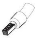
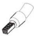
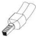
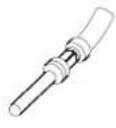
The CF 500 is used for crimping various types of crimp contacts:

- Ferrules

- T W I N f e r r u l e s

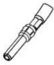
- Turned contacts

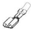
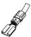
- Slip-on sleeves and flat plugs

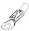
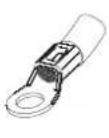
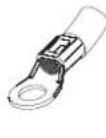
- Insulated cable lugs

- Cable lugs

- T u b e l u g s

Other crimp contacts on request.

Permitted operators

Only authorized and instructed operators may work with the CF 500.

The operator is responsible for all other persons within the workspace.

The owner must make the user manual available to the operator and ensure that the operator has read and understood it.

Phoenix Contact CF 500-230V - Permitted operators - 1

WARNING: Only use original crimp dies and replacement parts from Phoenix Contact.

1.2 Workplaces

Phoenix Contact CF 500-230V - Workplaces - 1

NOTE: During operation and storage, avoid the following:

– Humid or dusty places and
- Locations exposed to high levels of heat, direct sunlight or low temperatures (operating range: 10^ to 40^ ).

Phoenix Contact CF 500-230V - Workplaces - 2

NOTE: Do not spill liquids on the CF 500.

Do not expose the CF 500 to strong vibrations or shocks.

1.3 For your safety

Phoenix Contact CF 500-230V - For your safety - 1

WARNING: The protective cover is fitted for the safety of the operator. Under no circumstances must it be modified, removed or bypassed by means of alterations.

Phoenix Contact CF 500-230V - For your safety - 2

WARNING: The CF 500 must only be operated with the protective cover attached.

Disconnect the mains plug prior to all work that requires removal of the protective cover (e.g., crimping die adjustment).

Switch off the electric crimper during breaks and when the device is not being used.

For reasons of safety, the CF 500 automatically switches off when the protective cover is removed.

Phoenix Contact CF 500-230V - For your safety - 3

WARNING: Disconnect the mains plug before opening the housing.

2 Description of the CF 500

2.1 Supplied as standard
Phoenix Contact CF 500-230V - Supplied as standard - 1

text_image Technical diagram showing labeled components of an electrical device, including a control box, cable, and motor.

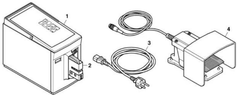
1 Basic device CF 500

2 Protective cover

3 Power cable

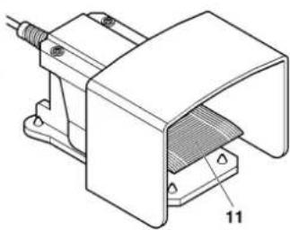
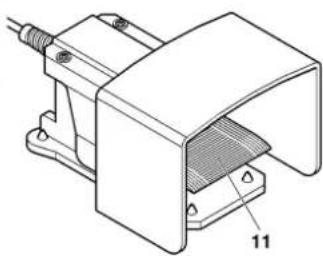
4 Foot pedal

User manual

2.2 Overview of the operating components
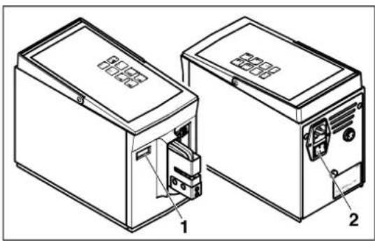
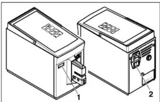
Phoenix Contact CF 500-230V - Overview of the operating components - 1
text_image Technical diagram of a device with numbered components, likely an electrical or mechanical assembly.

Phoenix Contact CF 500-230V - Overview of the operating components - 2

text_image Technical diagram of a device with numbered parts labeled 6, 7, 8, 9, and 10

Phoenix Contact CF 500-230V - Overview of the operating components - 3

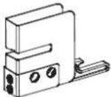
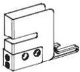
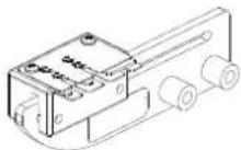
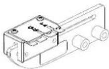
natural_image Technical line drawing of a mechanical clamp or bracket component (no text or symbols)

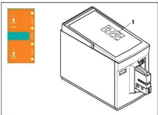
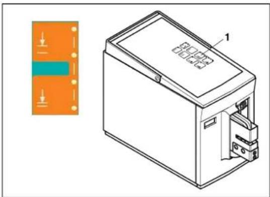
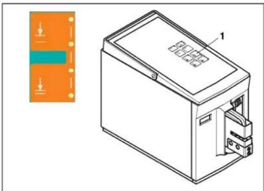
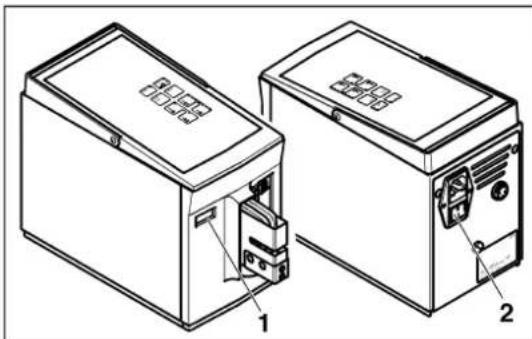
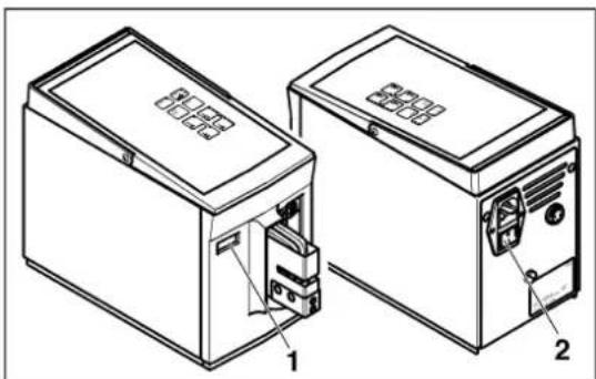
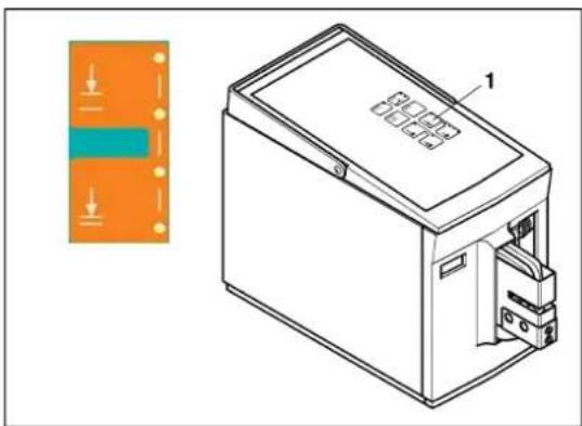
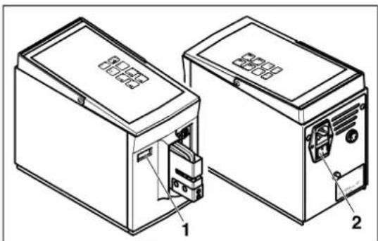
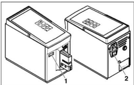
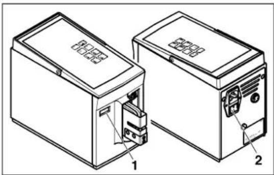
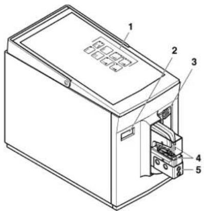
1 Control panel Selection of operating functions and display of device states.
2 Counter The counter records each complete crimping process. The counter reading is saved for approximately one week when the device is switched off.
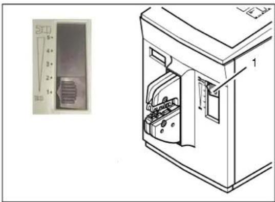
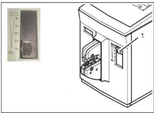
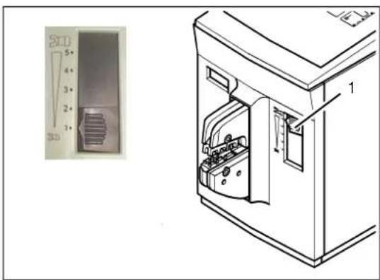
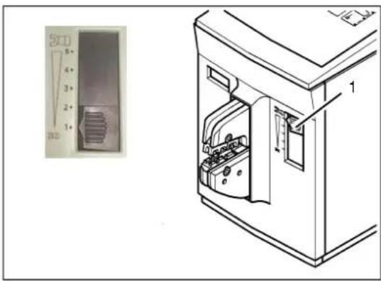
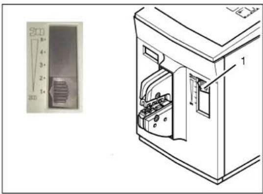
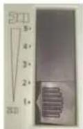
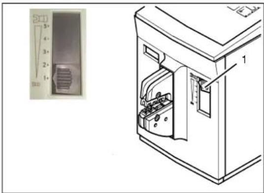
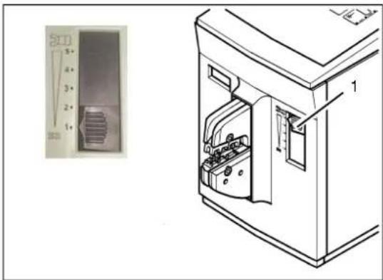
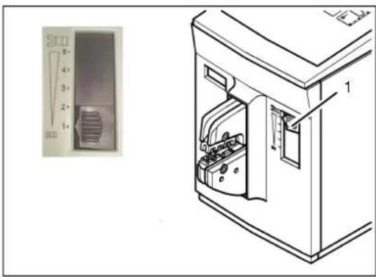
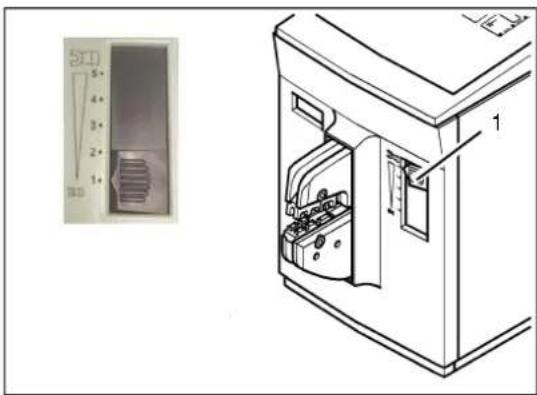
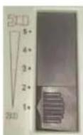
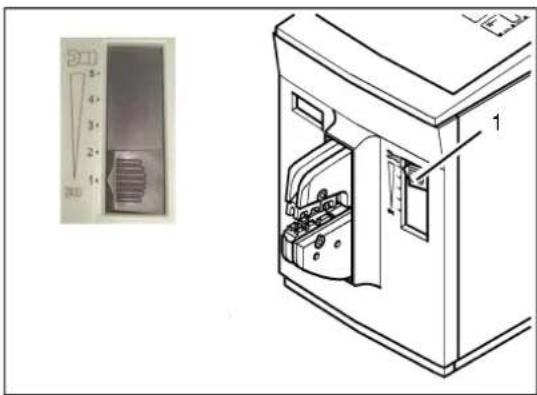
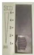
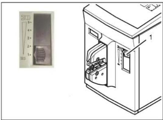
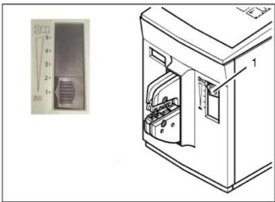
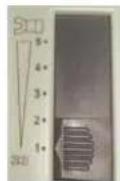
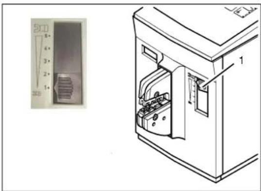
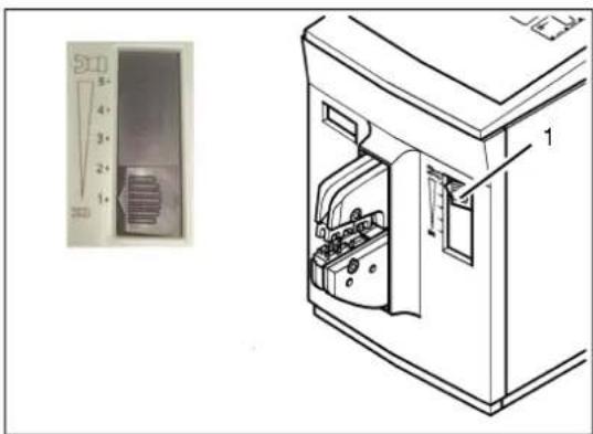
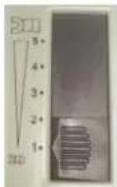
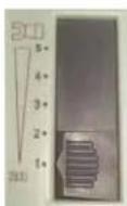
3 Adjusting slide The adjusting slide sets the area in which the crimping die is compressed with full force. If the die meets with resistance outside this area, the crimping pliers are opened immediately. (1 = minimum area, 5 = maximum area.)
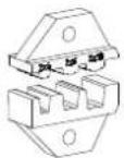
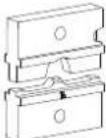
4 Crimping die Positions the crimp contact and crimps this with the wire.
5 Protective cover The protective cover prevents injury in the crimping die danger zone. The CF 500 can only be operated when the protective cover is fully attached.
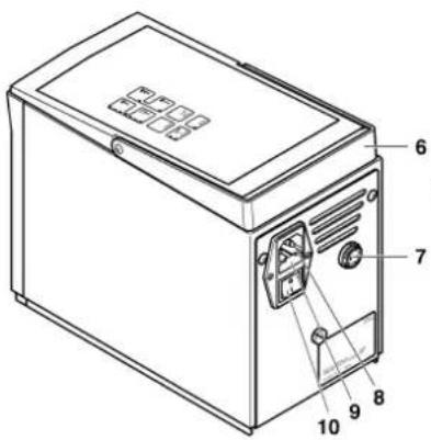
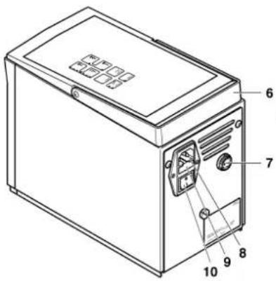
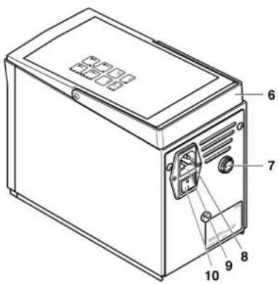
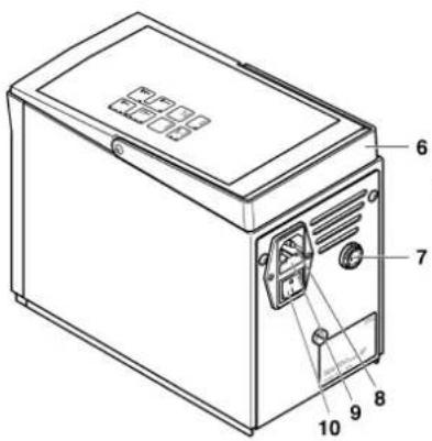
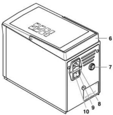
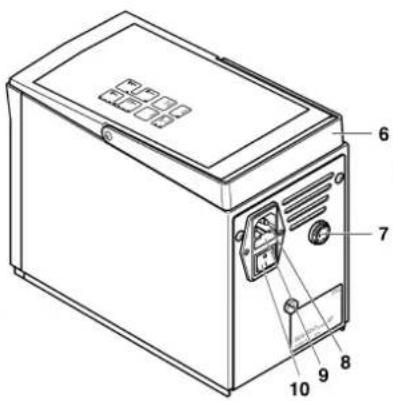
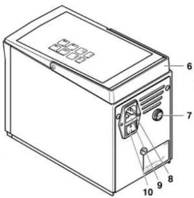
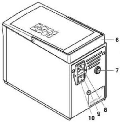
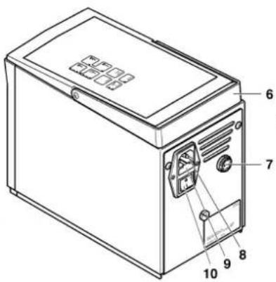
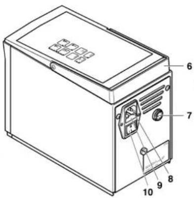
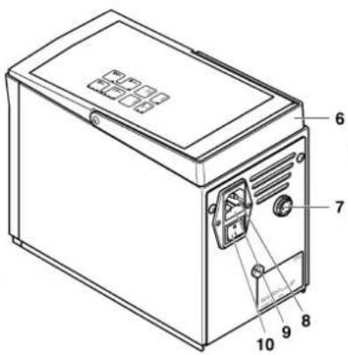
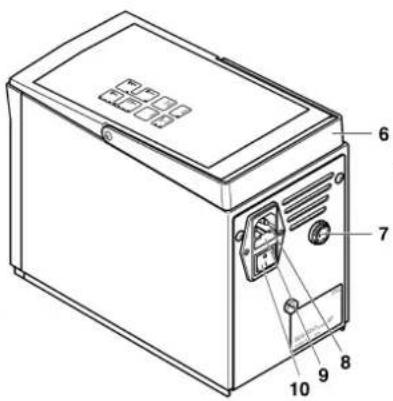
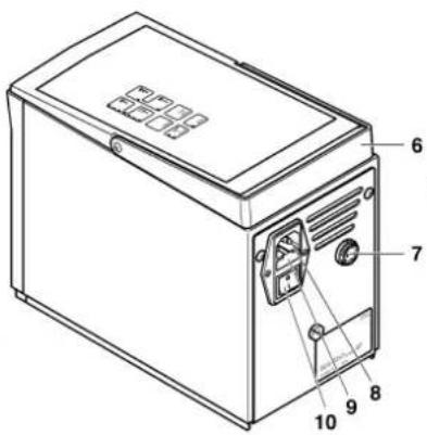
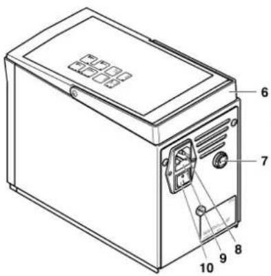
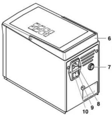
6 Carrier handle The carrier handle is used for transporting the CF 500.
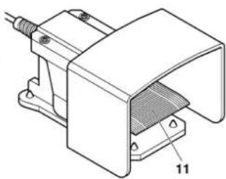
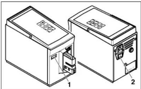
7 Foot pedal connection Device connection for the foot pedal.
8 Mains connection Device connection for the power cable.
9 Mains fuses Micro fuses integrated into the mains connection (2x).
10 Mains switch The mains switch switches the power supply on (I pressed) or off (O pressed). The "ready" LED lights up when switched on.
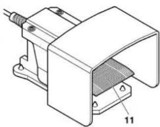
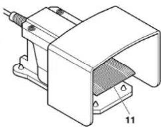
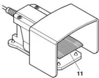
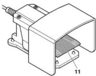
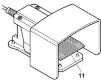
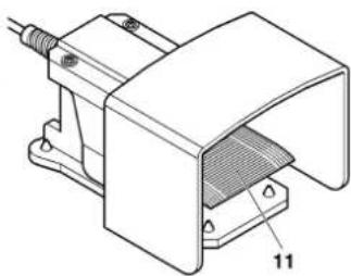
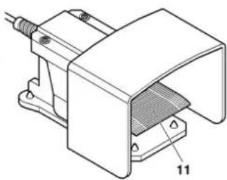
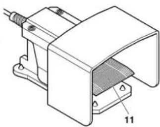
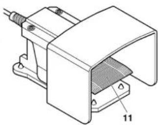
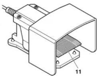
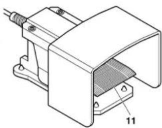
11 Foot pedal The foot pedal initiates the crimping process.

2.3 Function of the operating components

Phoenix Contact CF 500-230V - Function of the operating components - 1

"Ready" LED – indicates that the unit is ready for operation.
Phoenix Contact CF 500-230V - Function of the operating components - 2

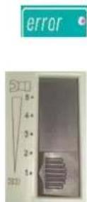
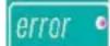
"Error" LED – indicates that crimping failed or that there is a malfunction.

Phoenix Contact CF 500-230V - Function of the operating components - 3

"Reset" button – resets the counter reading to zero.

Phoenix Contact CF 500-230V - Function of the operating components - 4

Press the "enter" button, the LED goes out and you can continue to crimp.
Phoenix Contact CF 500-230V - Function of the operating components - 5

"Operating mode 1" – switches the CF 500 to operating mode 1 (LED lights up). In operating mode 1, the crimping process takes place in one step.
Phoenix Contact CF 500-230V - Function of the operating components - 6

"Service" LED – indicates that the CF 500 requires servicing. We recommend servicing by Phoenix Contact after 500,000 crimping processes in order to ensure a consistent level of crimping quality.

Phoenix Contact CF 500-230V - Function of the operating components - 7

"Operating mode 2" button – switches the CF 500 to operating mode 2 (LED lights up). In operating mode 2, the crimping process takes place in two steps. In the first step, only the contact is fixed in the die.
Phoenix Contact CF 500-230V - Function of the operating components - 8

"Enter" button – clears the "Error" LED.

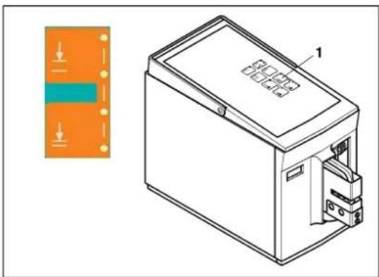
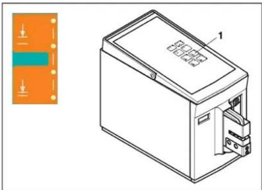
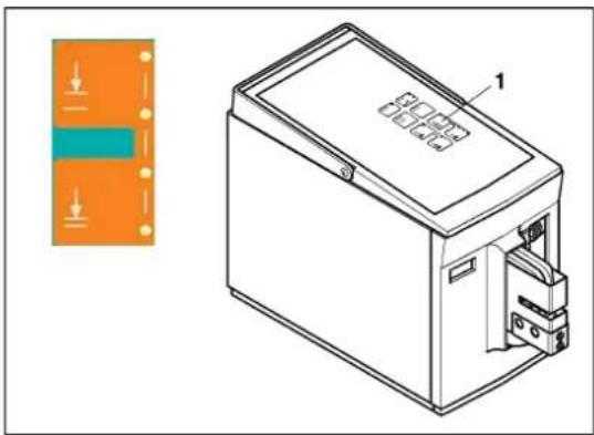
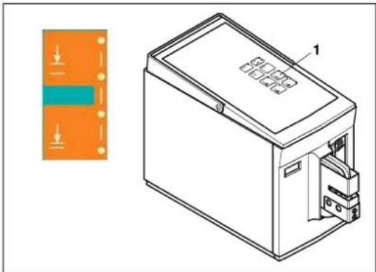
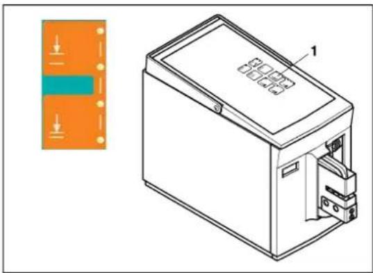
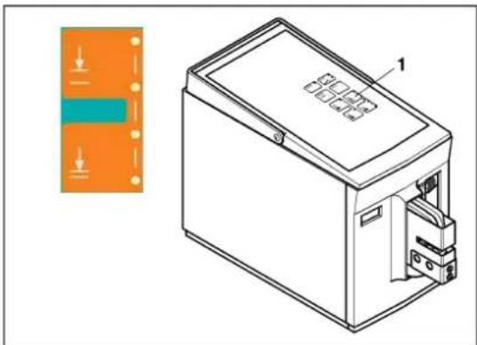
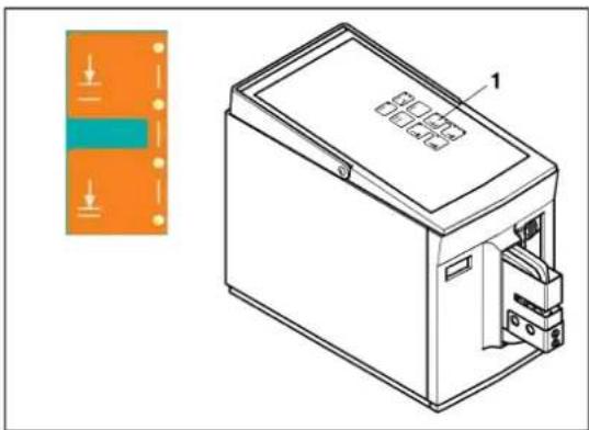
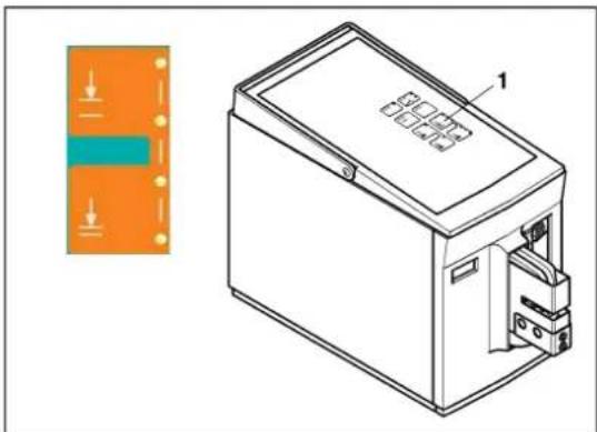
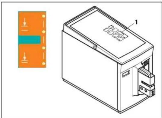
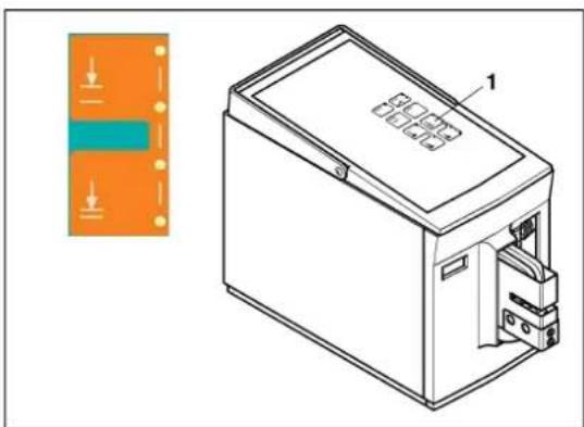
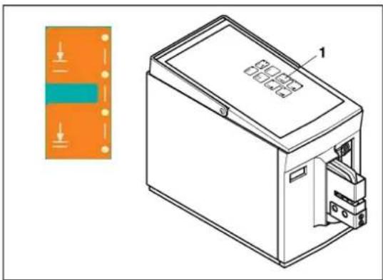
Buttons for limiting the opening – the opening of the crimping die can be adjusted by pressing the upper (open) or lower (close) button. The LEDs indicate the opening status:

- 4 LEDs light up: Maximum opening

- No LEDs light up: Minimum opening

Changes are only effective once the next crimping procedure has been carried out.

2.4 Scope of use of the CF 500

The CF 500 electric crimper is used for crimping crimp contacts.

By using different crimping dies, various types of crimp contacts with a wide range of cross sections can be processed.

The CF 500 can be operated in two different operating modes:

  • Operating mode 1: The crimp contact is crimped when the foot pedal is pressed.
  • Operating mode 2: The foot pedal is pressed twice. The first press secures the inserted contact in the die. The second time the foot pedal is pressed, the crimp contact is crimped.

The press capacity can be adjusted. This prevents damage to the tools and faulty crimping due to incorrectly inserted contacts.

The opening stroke of the crimping die can be changed by simply pressing a button.

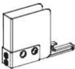
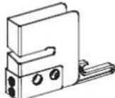
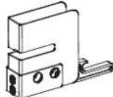
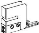
For precise crimping, a moveable locator, which positions the contacts directly under the crimping stamp, can be fitted.

Available crimping dies

Available crimping dies are listed in the "Crimping dies and protective covers" ordering data on page 19. A protective cover with a suitable insertion slot is assigned to each crimping die.

3 Starting up the CF 500

3.1 Overview

To start up the electric crimper, you must carry out the following steps:

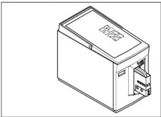
  • Set up the CF 500
  • Remove the protective cover
  • Fit the crimping die
  • Attach the protective cover
  • Connect and switch on the CF 500
    – Center the crimping die
  • Adjust the crimping die
    – Prepare the unit for operation
  • Set the optimum press capacity start
  • Set the optimum opening stroke

3.2 How to proceed
Phoenix Contact CF 500-230V - How to proceed - 1

natural_image Line drawing of a rectangular electronic device with a lid and internal ports (no text or symbols)
Phoenix Contact CF 500-230V - How to proceed - 2

text_image Technical diagram showing a mechanical assembly with labeled parts and directional arrows indicating movement or assembly.

Setting up the CF 500

Phoenix Contact CF 500-230V - Setting up the CF 500 - 1

NOTE: The device must be set up on a level and horizontal surface.

Phoenix Contact CF 500-230V - Setting up the CF 500 - 2

NOTE: During operation and storage, avoid the following:

- Humidordus

- Locations exposed to high levels of heat, direct sunlight or low temperatures (operating range: 10°C ... 40°C).

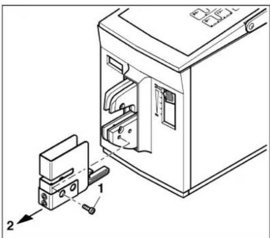
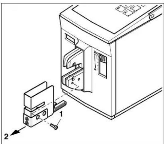
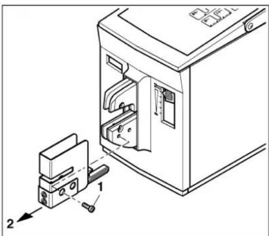
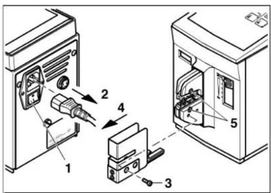
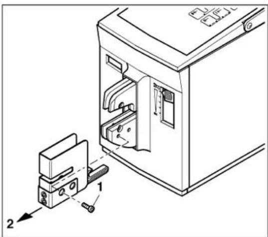
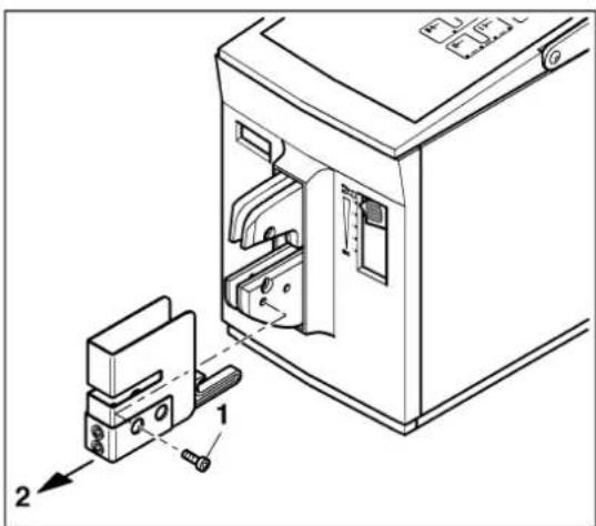
Removing the protective cover

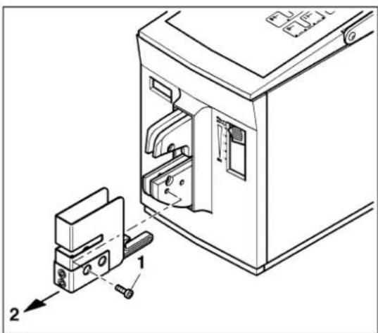
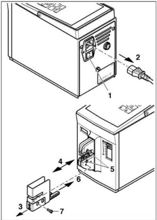
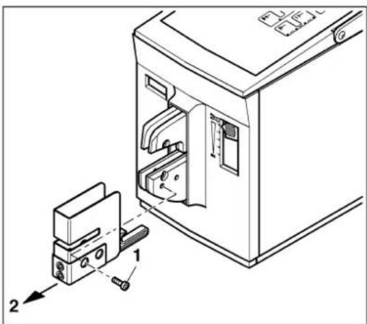
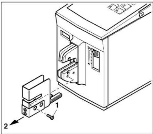
Phoenix Contact CF 500-230V - Removing the protective cover - 1

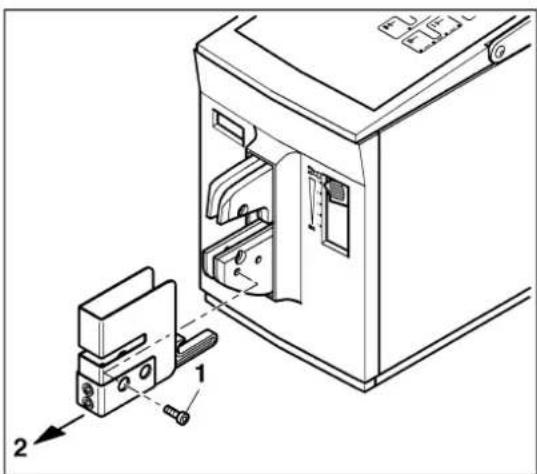
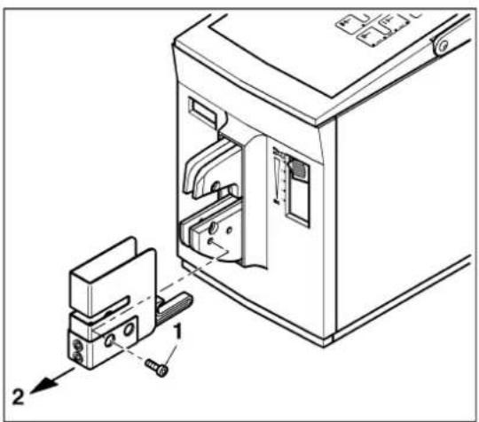
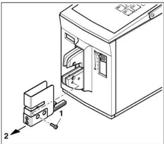
WARNING: Risk of injury

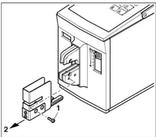
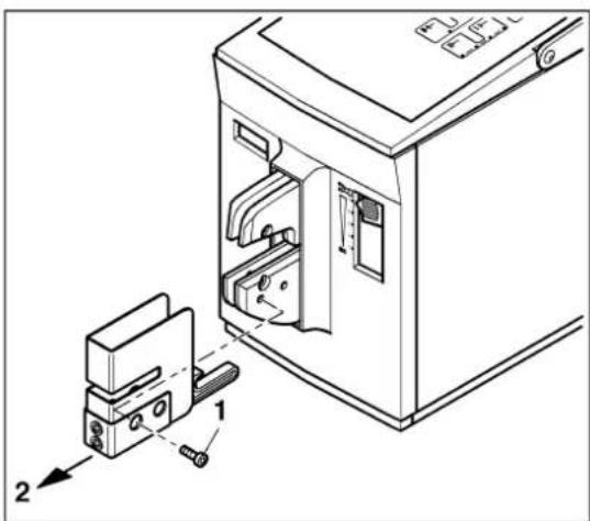
Disconnect the mains plug before removing the protective cover.

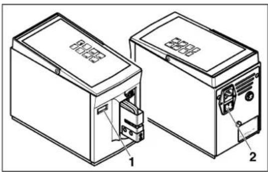
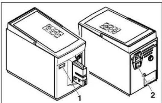
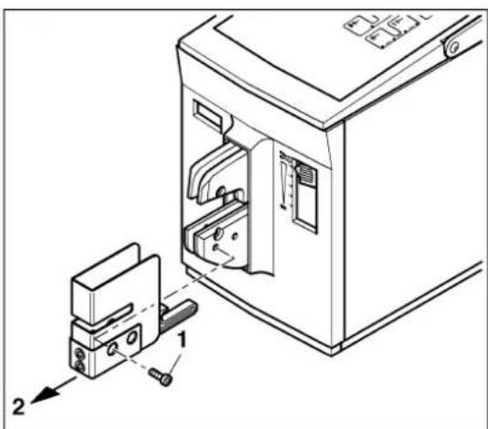
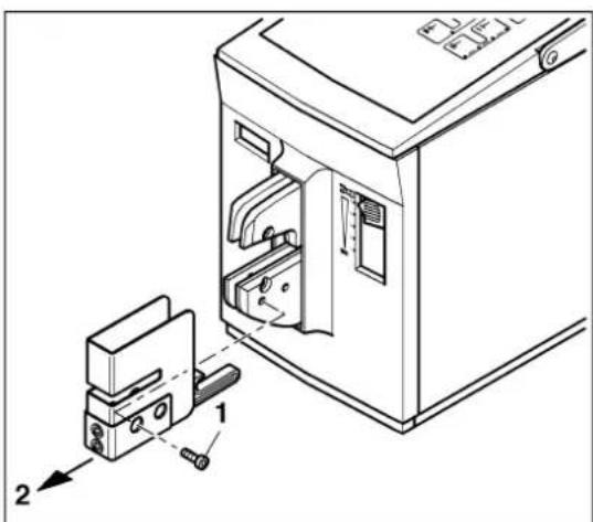
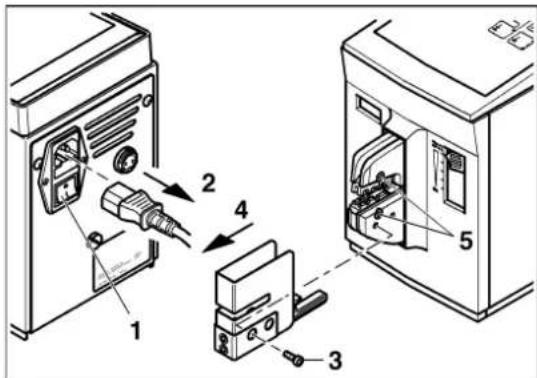
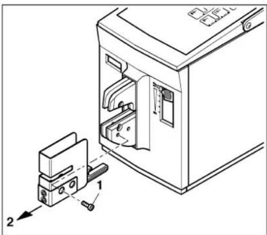
  • Unscrew the screw (1).
  • Remove the protective cover (2).

Phoenix Contact CF 500-230V - Removing the protective cover - 2

text_image Technical diagram of a refrigerator interior with labeled parts and directional arrows indicating movement or assembly.

Phoenix Contact CF 500-230V - Removing the protective cover - 3

text_image Technical diagram showing a device with two labeled parts and an open electrical box, illustrating assembly or installation steps.

Phoenix Contact CF 500-230V - Removing the protective cover - 4

text_image Technical diagram showing labeled components of an electrical device with numbered parts and wiring connections

Fitting the crimping die

Phoenix Contact CF 500-230V - Fitting the crimping die - 1

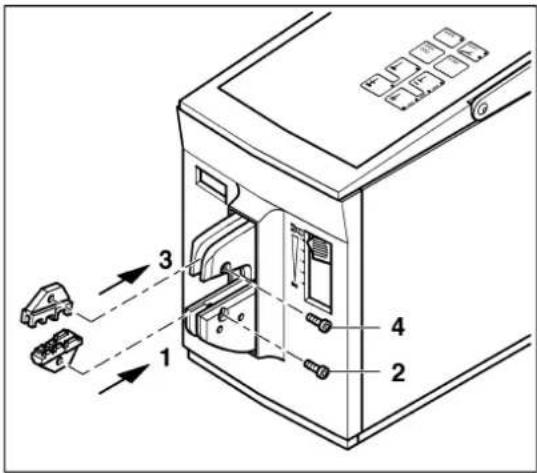
NOTE: Observe the mounting position:

- Small cross section to the front

– Large cross section to the rear

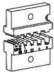
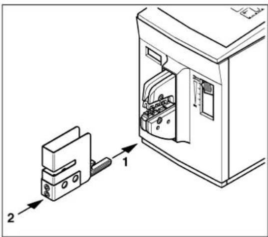
  • Insert the lower crimping die (1).
    • G e n t l y tighten the screw (2).
  • Insert the upper crimping die (3).
    • G e n t l y tighten the screw (4).

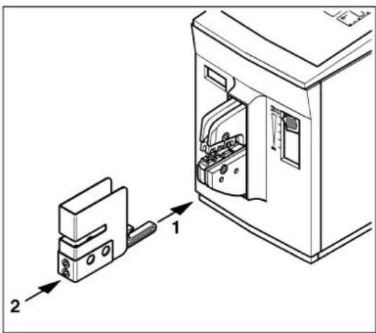
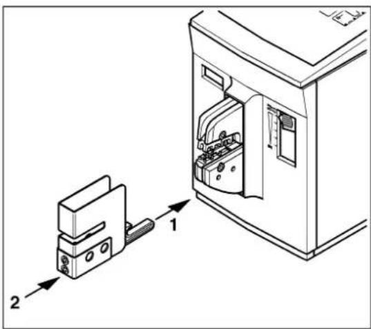
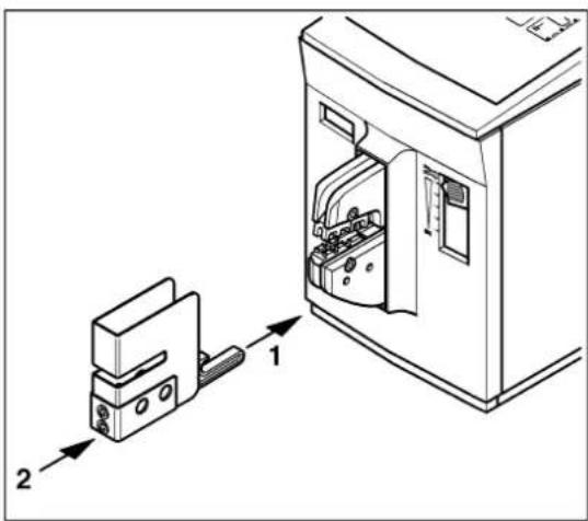
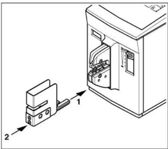
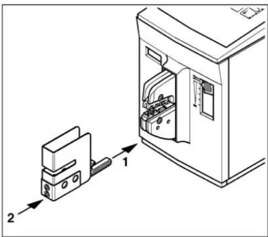
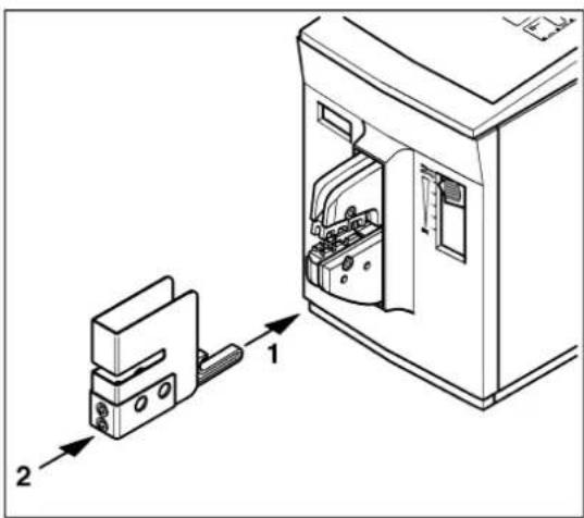
Attaching the protective cover

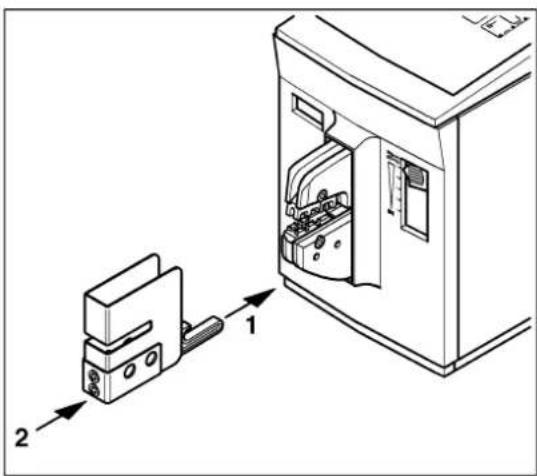
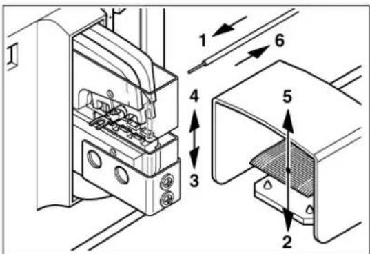
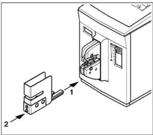
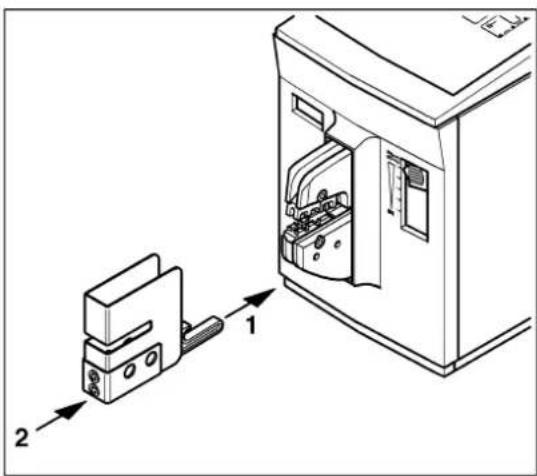
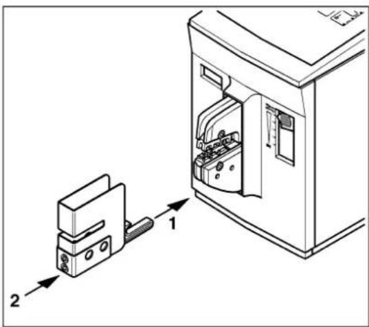
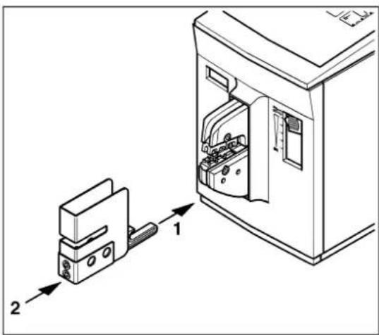
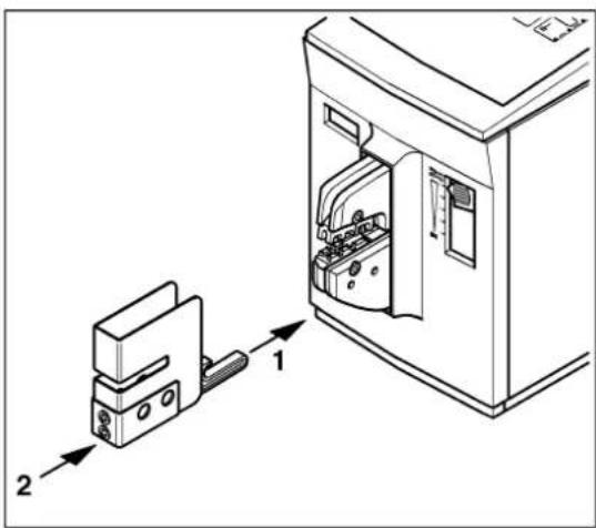
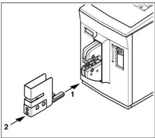
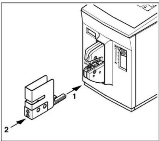
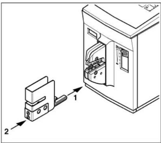
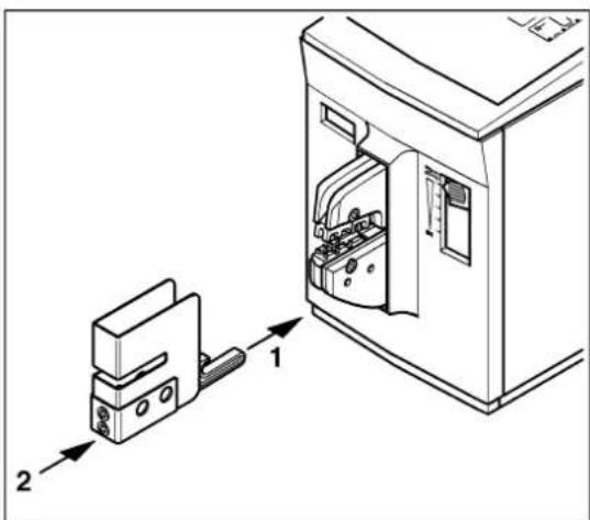
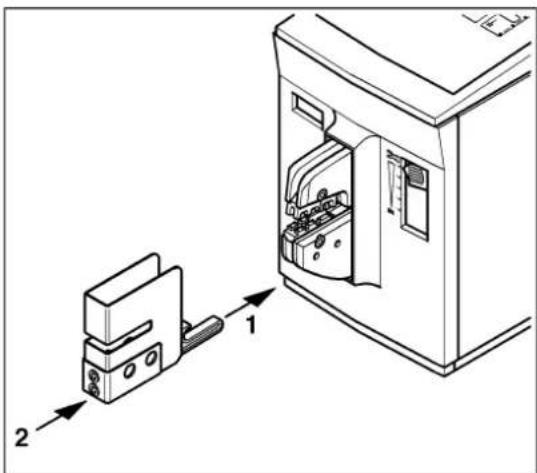
- Insert the security pin (1) into the lower crimping die and slide the protective cover (2) in until you feel it engage.

Phoenix Contact CF 500-230V - Attaching the protective cover - 1

WARNING: The CF 500 must only be operated with the protective cover attached.

Phoenix Contact CF 500-230V - Attaching the protective cover - 2

NOTE: If the protective cover is missing or incorrectly attached, then the CF 500 power supply disconnects.

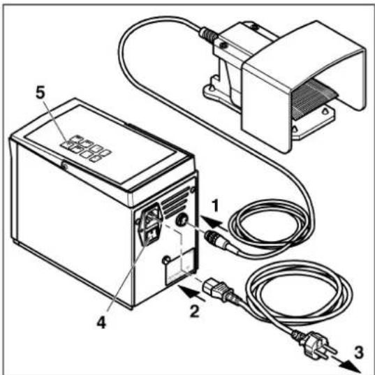
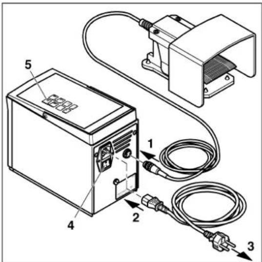
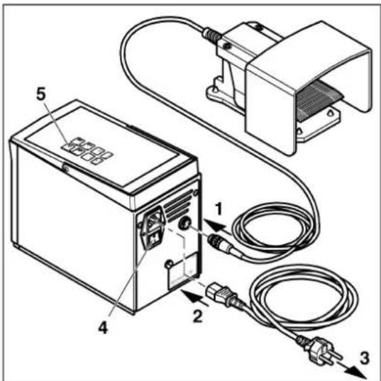
Connecting and switching on the CF 500

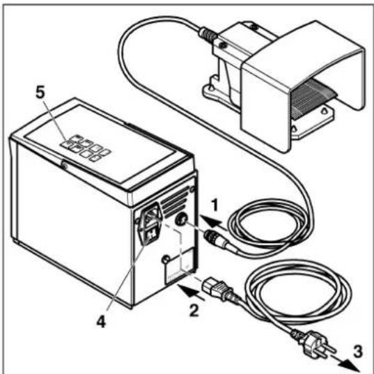
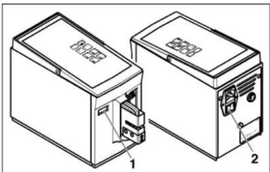
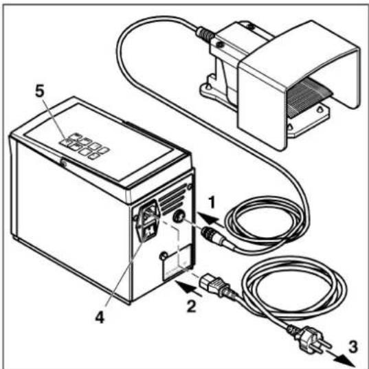
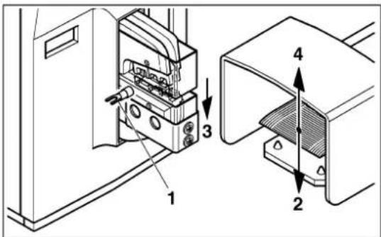
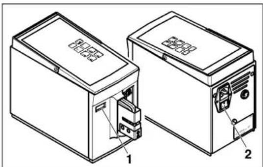
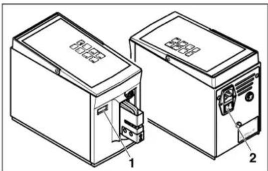
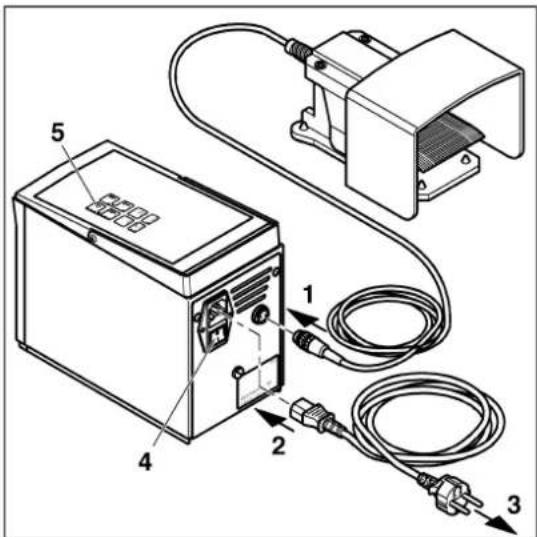
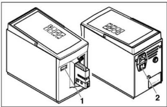
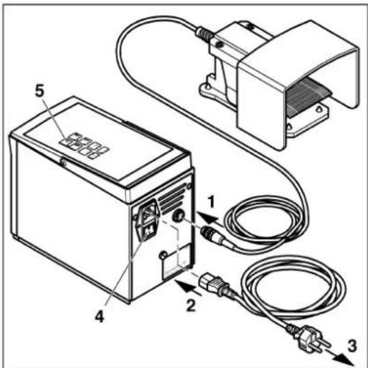
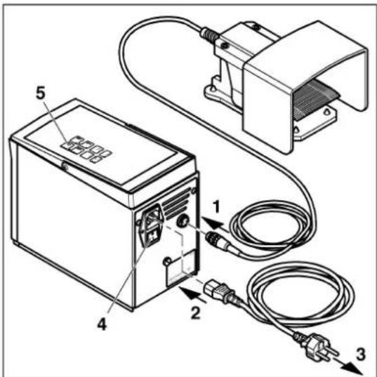
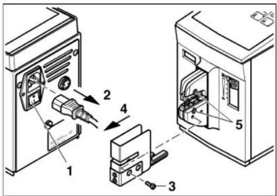
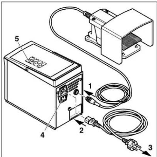
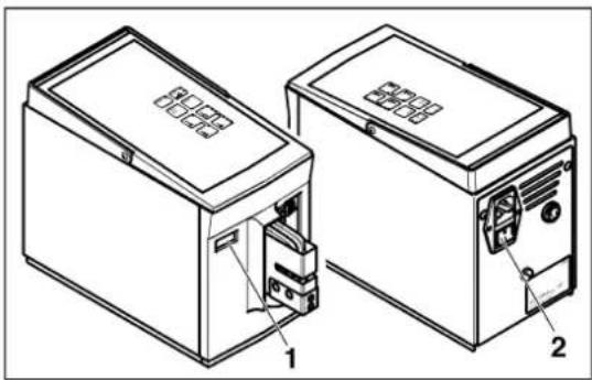
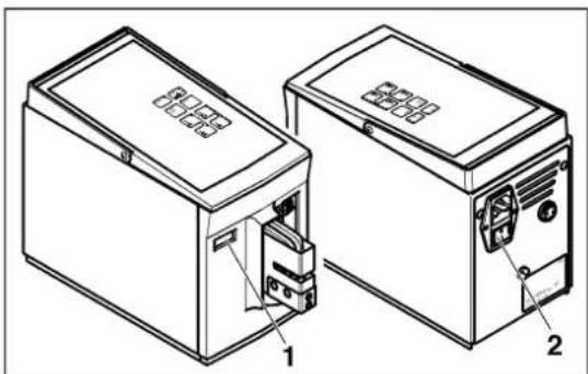
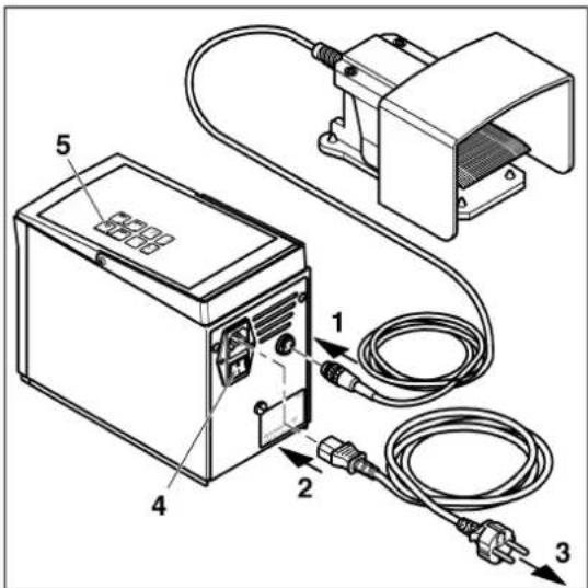
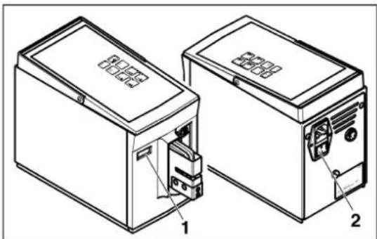
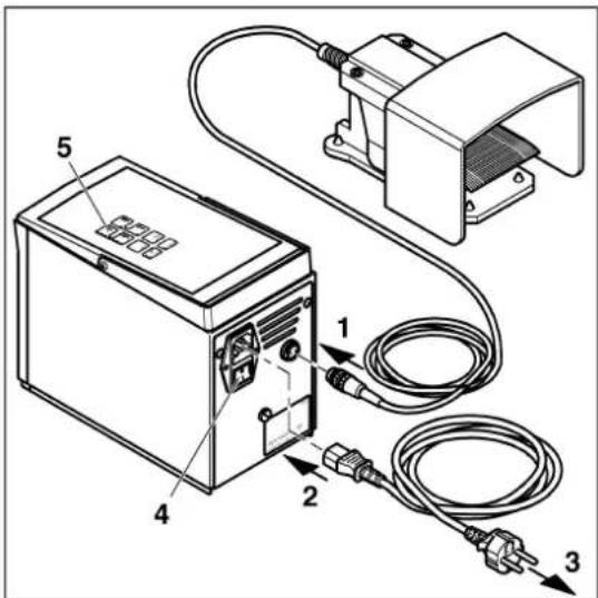
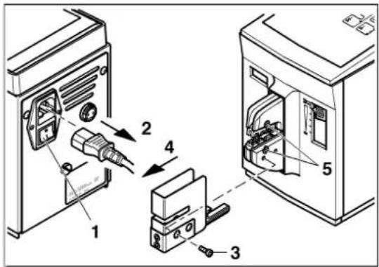
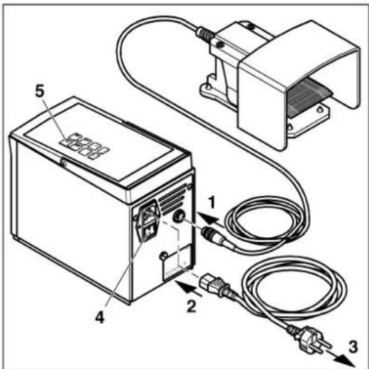
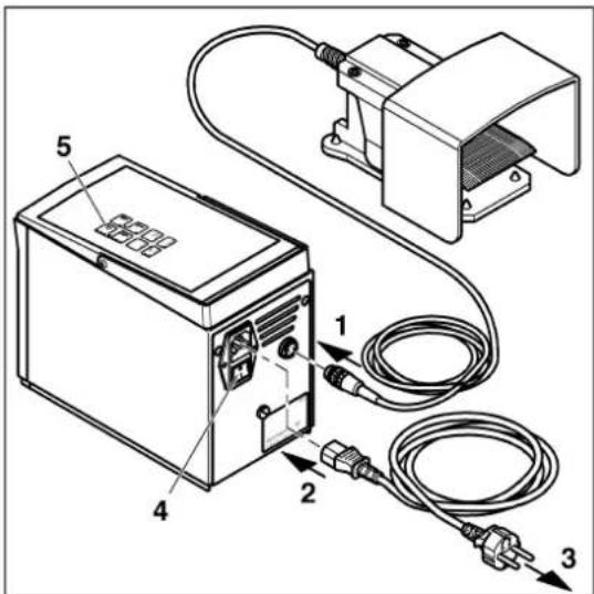
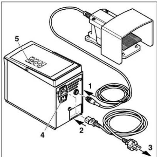
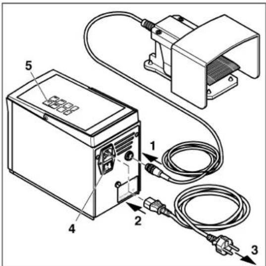
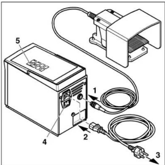
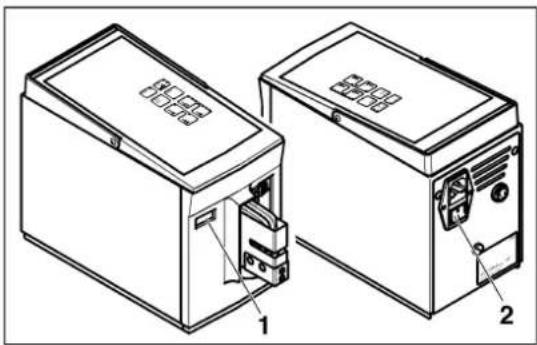
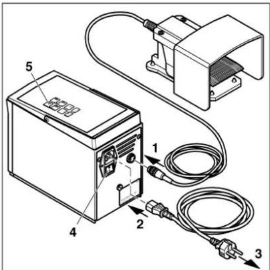
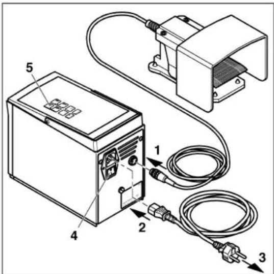
- Connect the foot pedal (1) to the foot pedal connection.

Phoenix Contact CF 500-230V - Connecting and switching on the CF 500 - 1

NOTE: The CF 500 is available in two versions for 230 V and 120 V. Make sure the mains connection is correct (see rating plate).

  • Connect the mains plug (2) to the mains connection and the shock-proof plug (3) to the socket.
  • Switch on the CF 500 with the mains switch (4) (press I). The "ready" LED lights up (5).
Phoenix Contact CF 500-230V - Connecting and switching on the CF 500 - 2

text_image Technical diagram of an electrical enclosure with labeled components and wiring connections

Phoenix Contact CF 500-230V - Connecting and switching on the CF 500 - 3

text_image Technical diagram showing installation steps of a computer case with labeled components and cable connections

Centering the crimping die

Phoenix Contact CF 500-230V - Centering the crimping die - 1

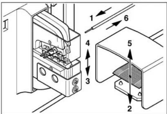
NOTE: The crimping die bore holes have some play for the mounting screws. Therefore you need to center and adjust the crimping die.

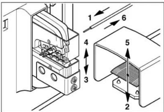
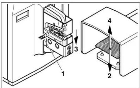
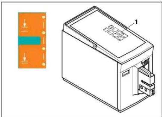
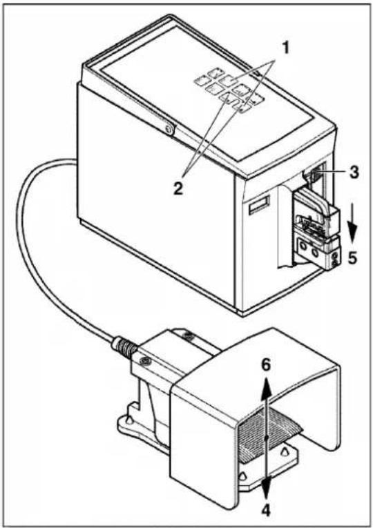
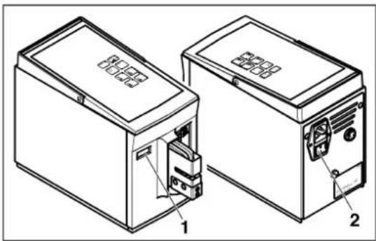
  • Press the "operating mode 2" and "enter" buttons simultaneously (1).
  • The LEDs for the "operating mode 1 + 2" buttons flash (2).
  • Push the adjusting slide (3) to position 1.

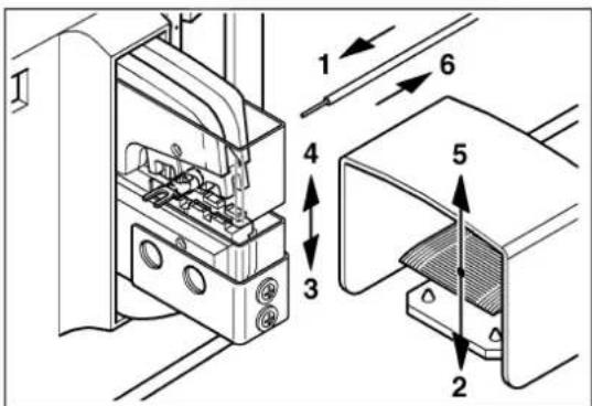
Phoenix Contact CF 500-230V - Centering the crimping die - 2

NOTE: Only release the foot pedal once the crimping die is closed. Otherwise it opens automatically, adjustment mode is terminated, and the "error" LED lights up.

  • Press and hold down the foot pedal (4).
  • The crimping die (5) closes slowly, until it meets with resistance and centers itself.
  • Release the foot pedal (6).

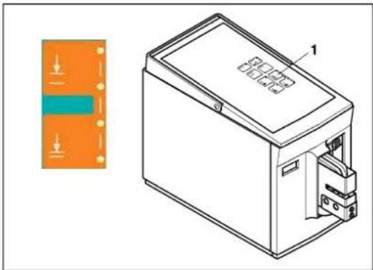
Adjusting the crimping die

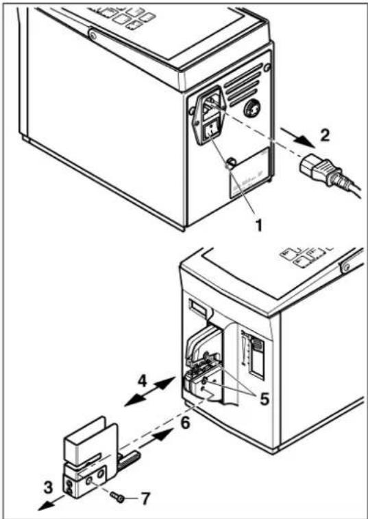
Phoenix Contact CF 500-230V - Adjusting the crimping die - 1

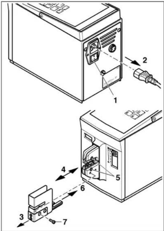
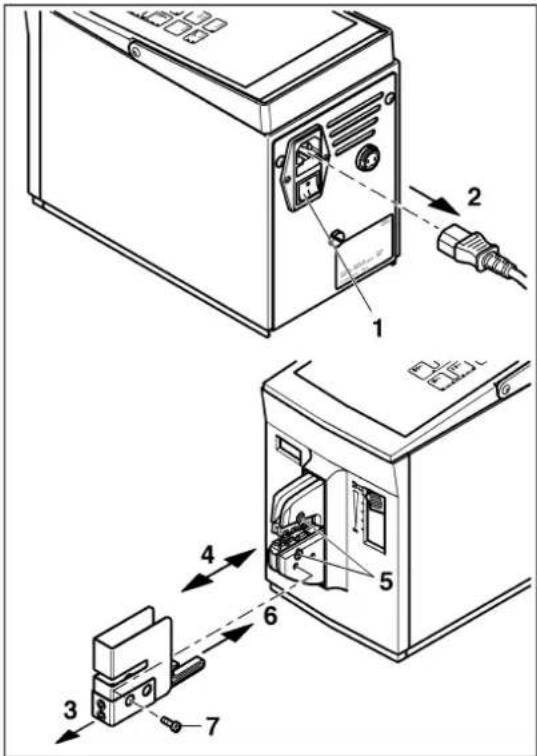
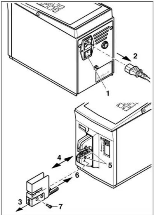
WARNING: Risk of injury

Disconnect the mains plug before removing the protective cover.

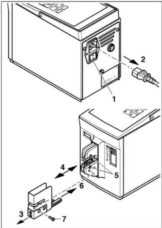
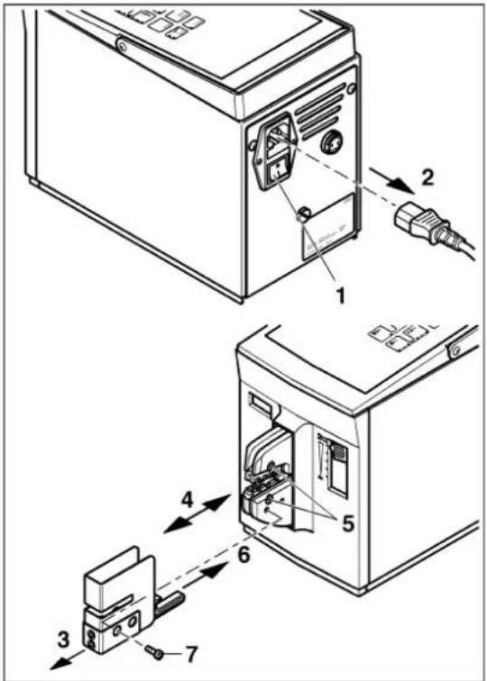
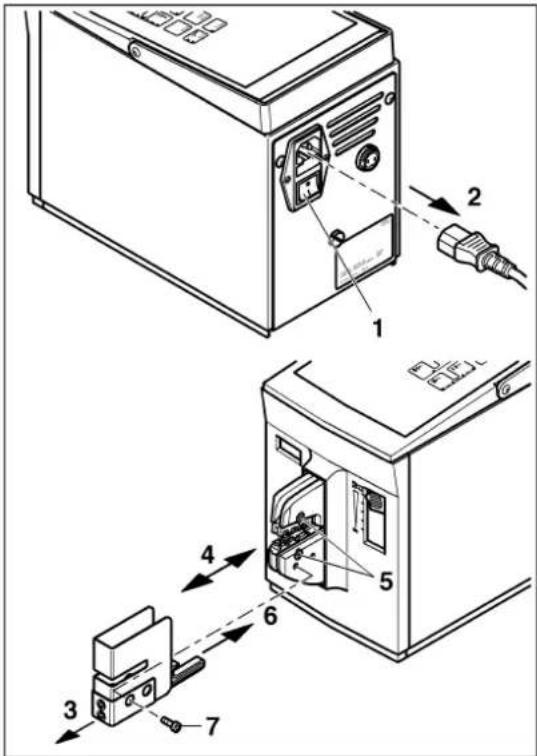
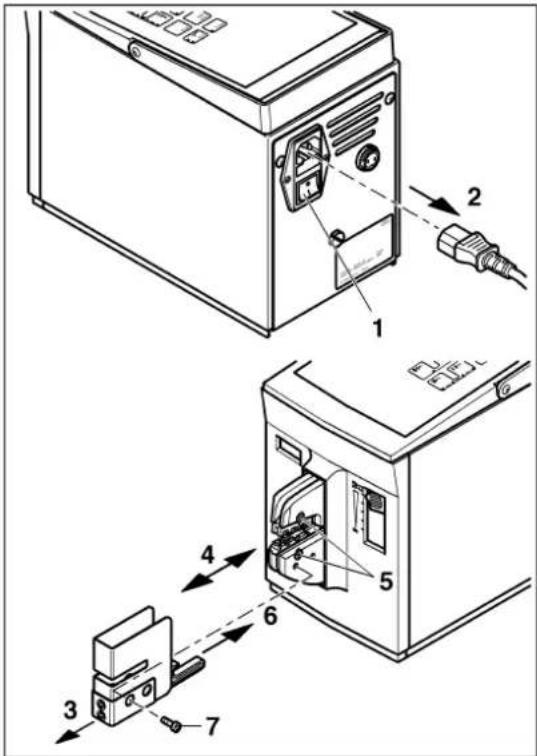
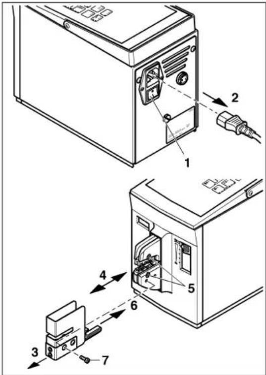
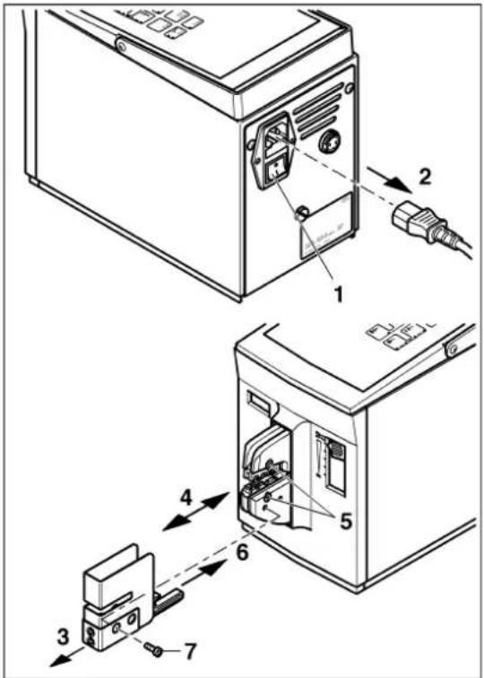
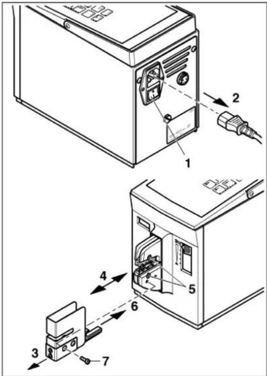
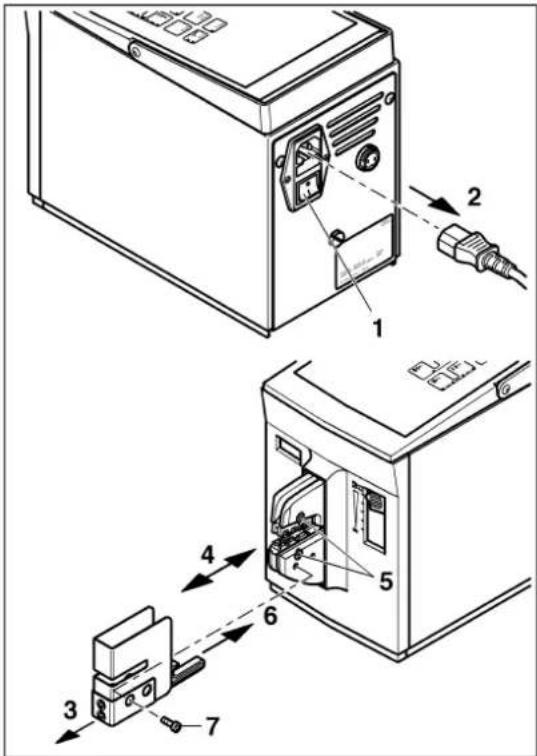
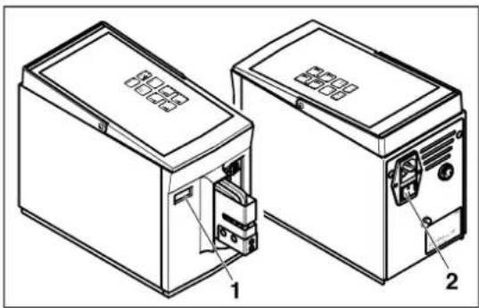
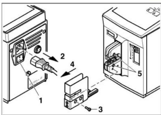
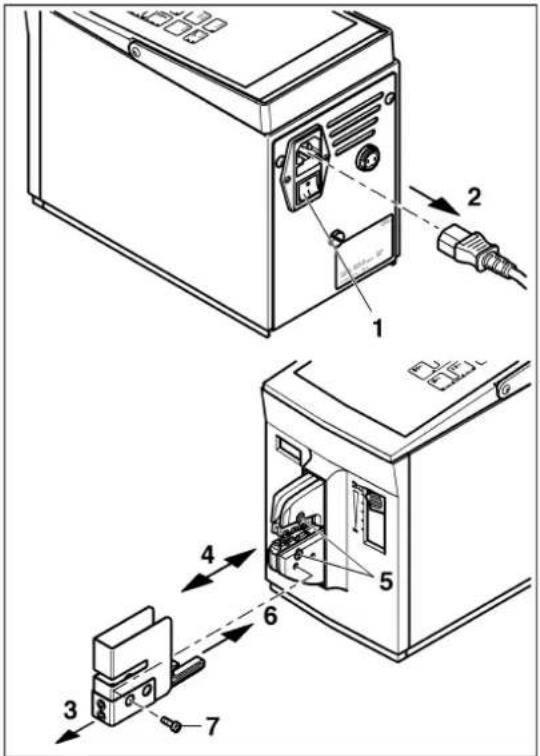
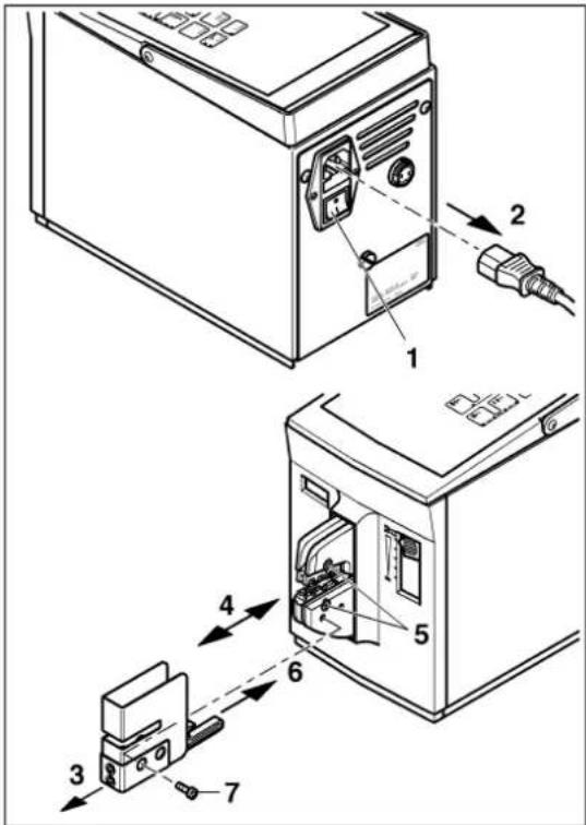
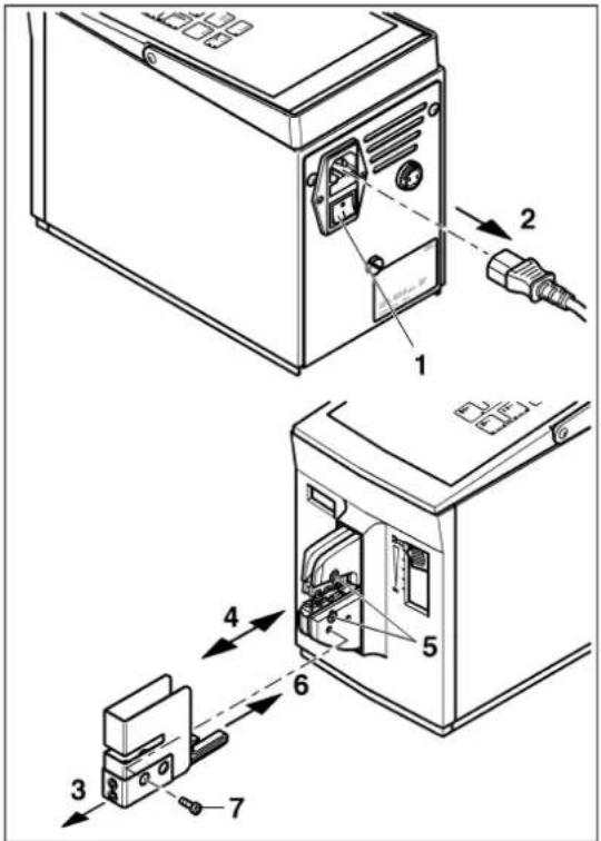
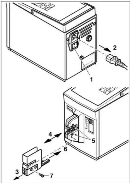
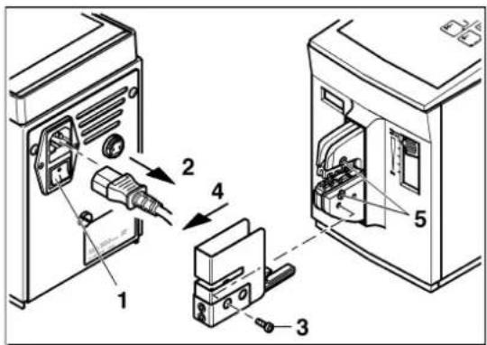
  • Switch off the CF 500 with the mains switch (1) (press 0).
  • Disconnect the mains plug (2).
  • Unscrew the screw (7).
  • Remove the protective cover (3).
  • Check the centering of the crimping die, adjust if necessary (4).
  • Tighten the screws (5).
  • Attach the protective cover (6) and tighten the screw (7).
Phoenix Contact CF 500-230V - WARNING: Risk of injury - 1

text_image Technical diagram of an electrical switchgear assembly with numbered components and exploded view

Phoenix Contact CF 500-230V - WARNING: Risk of injury - 2

text_image PLD 5 4 3 2 1 SB 1

Phoenix Contact CF 500-230V - WARNING: Risk of injury - 3

natural_image Technical line drawing of a mechanical device with labeled components and an orange panel on the left (no text or symbols present)

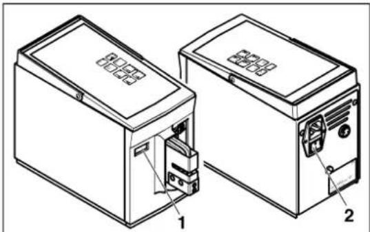
Preparing the unit for operation

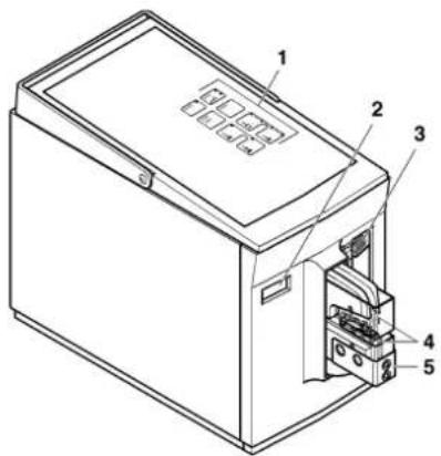
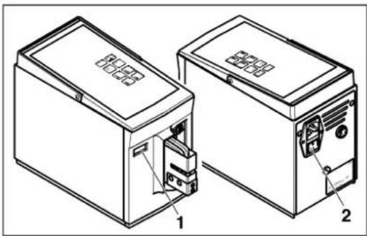
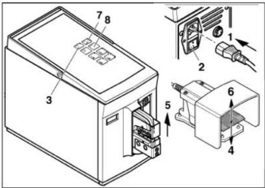
  • Plug in the mains plug (1).
  • Switch on the mains switch (2) (press I). The "ready" LED lights up (3).
  • Press the foot pedal (4).
  • The crimping die (5) opens automatically; release the foot pedal (6). The "error" LED lights up (7).
  • Press the "enter" button (8). The CF 500 is ready to operate.

Phoenix Contact CF 500-230V - Preparing the unit for operation - 1

NOTE: The device is set to operating mode 2. Check the operating mode before each use.

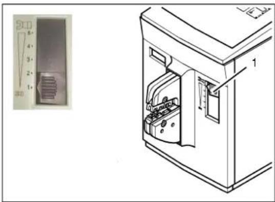
Setting the optimum press capacity start (1 ... 5)

  • Push the adjusting slide (1) into position 1.
  • Use the button to set "operating mode 1".
  • Press the foot pedal.
    One crimp process is performed without an inserted crimp contact. If the "error" LED lights up, check the position of the crimping die (see page 13).
  • Insert the wire and the crimp contact.

Phoenix Contact CF 500-230V - Setting the optimum press capacity start (1 ... 5) - 1

NOTE: Ensure the cross section is correct.

  • Press the foot pedal.
  • If the "error" LED lights up, move the adjusting slide up one position.
  • Press the "enter" button.
  • Repeat the process until the "error" LED no longer lights up.
  • To compensate for any material tolerances, push the adjusting slide up one more position.

Setting the optimum opening stroke

  • Press the upper button until all four LEDs light up. The maximum opening stroke is set.

- Carry out the crimping process.

Phoenix Contact CF 500-230V - Setting the optimum opening stroke - 1

NOTE: Changes to settings only take effect after the next crimping process.

  • If the opening stroke is too large, press the lower button so that only three LEDs light up.
  • Carry out the crimping process.
  • Repeat the process until the optimum opening stroke is set.

4 Operation

4.1 One-step crimping

Phoenix Contact CF 500-230V - One-step crimping - 1

text_image Technical diagram of a device with numbered components, showing front and side views of a device casing.

Phoenix Contact CF 500-230V - One-step crimping - 2

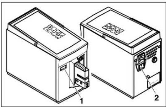
Setting operating mode 1

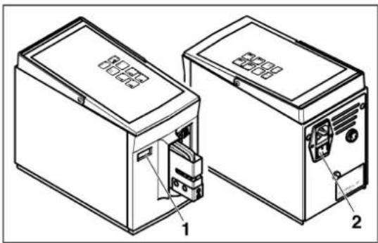
  • Switch on the CF 500 with the mains switch (1) (press I).
    The "ready" LED lights up (2).
  • Press the "operating mode 1" button (3).
  • If necessary, read the counter (4) and press the "reset" button to reset it to zero (5).
Phoenix Contact CF 500-230V - Setting operating mode 1 - 1

text_image Technical diagram of a device with numbered components and directional arrows indicating assembly or movement.

Phoenix Contact CF 500-230V - Setting operating mode 1 - 2

text_image Technical diagram of two electronic devices with labeled components, showing internal wiring and mounting parts.

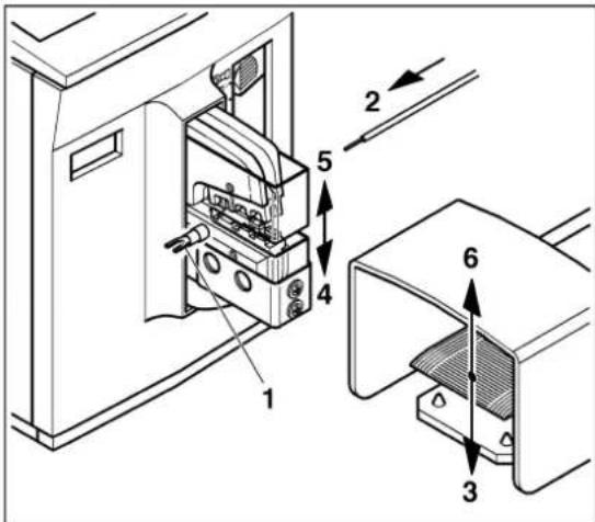
Crimping the crimp contact

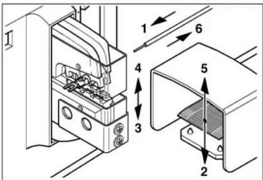
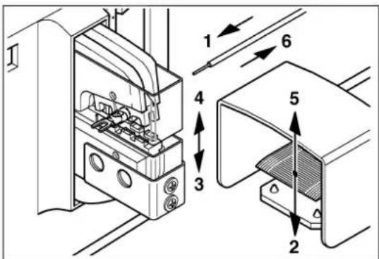
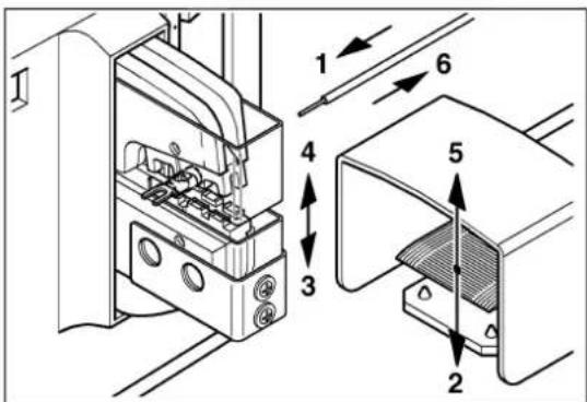
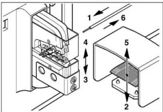
  • Center the crimp contact (1) on the lower crimping die.
  • Insert the wire (2) into the crimp contact.

Phoenix Contact CF 500-230V - Crimping the crimp contact - 1

NOTE: Ensure the cross section is correct.

  • Press the foot pedal (3) until the crimping die is completely closed (4).
  • The crimping die (5) opens automatically; release the foot pedal (6).
  • Remove the crimp contact with crimped wire (7).

Phoenix Contact CF 500-230V - Crimping the crimp contact - 2

NOTE: If there was a fault with the crimping, the "error" LED lights up (see page 17).

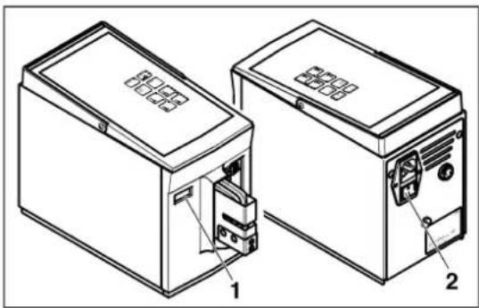
Shutting down

  • If necessary, read the counter (1).
  • Switch off the CF 500 with the mains switch (2) (press 0).

4.2 Two-step crimping

Phoenix Contact CF 500-230V - Two-step crimping - 1

text_image Technical diagram of a device with numbered components, showing front and side views of a device casing.

Phoenix Contact CF 500-230V - Two-step crimping - 2

Setting operating mode 2

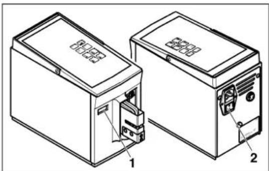
  • Switch on the CF 500 with the mains switch (1) (press I).
    The "ready" LED lights up (2).
  • Press the "operating mode 2" button (3).
  • If necessary, read the counter (4) and press the "reset" button to reset it to zero (5).
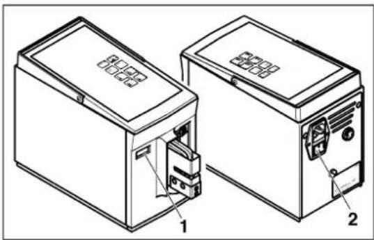
Phoenix Contact CF 500-230V - Setting operating mode 2 - 1

text_image Technical diagram showing mechanical assembly with numbered components and directional arrows indicating assembly steps

Phoenix Contact CF 500-230V - Setting operating mode 2 - 2

text_image Technical diagram showing labeled mechanical components with numbered parts and directional arrows indicating assembly or assembly.

Phoenix Contact CF 500-230V - Setting operating mode 2 - 3

text_image Technical diagram of two electronic devices with labeled parts, showing internal components and mounting points.

Clamping the crimp contact

Phoenix Contact CF 500-230V - Clamping the crimp contact - 1

NOTE: Ensure the cross section is correct.

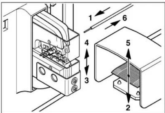
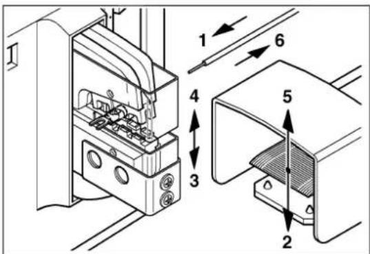
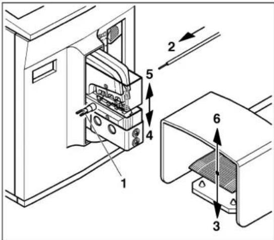
  • Center the crimp contact (1) on the lower crimping die.
  • Press the foot pedal (2) until the crimp contact is clamped (3).
  • Release the foot pedal (4).

Crimping the crimp contact

  • Insert the wire (1) into the crimp contact.
  • Press the foot pedal (2) until the crimping die is completely closed (3).
  • The crimping die (4) opens automatically; release the foot pedal (5).
  • Remove the crimp contact with crimped wire (6).

Phoenix Contact CF 500-230V - Crimping the crimp contact - 1

NOTE: If there was a fault with the crimping, the "error" LED lights up (see page 17).

Shutting down

  • If necessary, read the counter (1).
  • Switch off the CF 500 with the mains switch (2) (press 0).

5 Troubleshooting

5.1 "Error" LED lights up

Phoenix Contact CF 500-230V - "Error" LED lights up - 1

This malfunction can be caused by:

– Foot pedal released too soon
- Incorrect cross section selected
- Incorrectly set press capacity start (1 ... 5)
- Crimping die incorrectly adjusted

Phoenix Contact CF 500-230V - "Error" LED lights up - 2

Foot pedal released too soon

If the foot pedal is released too soon, the crimping die immediately opens up as far as its initial position.

  • Press the "enter" button.
    The "error" LED goes out.
  • Repeat the crimping process.

Phoenix Contact CF 500-230V - Foot pedal released too soon - 1

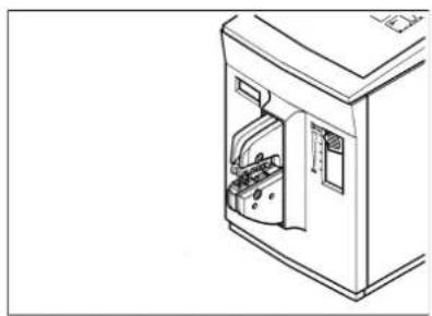
Incorrect cross section selected

If a crimp contact that is too large or another unsuitable object is inserted, the crimping process is interrupted due to overload and the crimping die immediately opens as far as its initial position.

  • Press the "enter" button.
    The "error" LED goes out.
  • Repeat the crimping process with the correct cross section.
Phoenix Contact CF 500-230V - Incorrect cross section selected - 1

natural_image Line drawing of a door with internal components, no text or symbols present

Phoenix Contact CF 500-230V - Incorrect cross section selected - 2

Incorrectly set press capacity start (1 ... 5)

The inserted contact is too large for the selected area.

  • Push the adjusting slide up one position.
  • Press the "enter" button.

The "error" LED goes out.

- Repeat the crimping process until the press capacity is optimally set.
Phoenix Contact CF 500-230V - Incorrectly set press capacity start (1 ... 5) - 1

text_image Technical diagram showing installation steps of an electrical switch or fuse device with labeled components

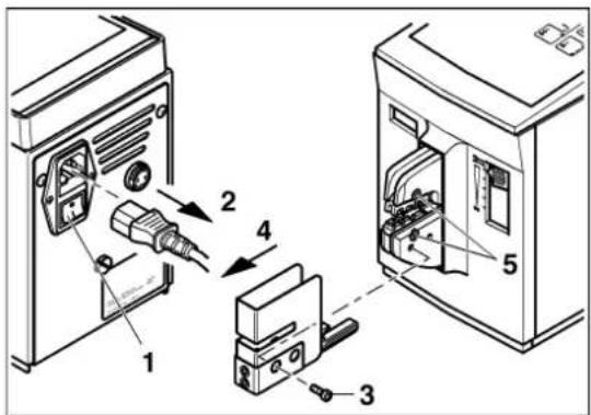
Crimping die incorrectly adjusted

Phoenix Contact CF 500-230V - Crimping die incorrectly adjusted - 1

WARNING: Risk of injury

Disconnect the mains plug before removing the protective cover.

  • Switch off the CF 500 with the mains switch (1) (press 0).
  • Disconnect the mains plug (2).
  • Unscrew the screw (3).
  • Remove the protective cover (4).
  • Loosen the screws (5).
  • Carry out the startup steps (see Section 3).

5.2 CF 500 will not switch on

The CF 500 will not switch on. The "ready" LED does not light up. This malfunction can be caused by:

- No mains connection

- M a i n s f u s e b l o w n

No mains connection

  • Check whether the mains plug is connected to the CF 500 mains connection and the shock-proof plug is connected to the mains socket.
  • Make sure that the power supply at the mains socket is OK.

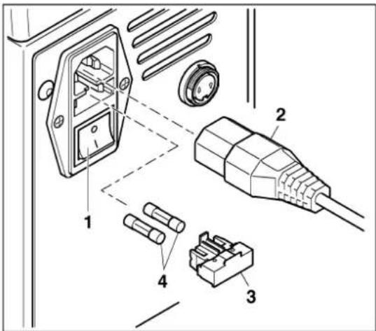
Mains fuse blown
Phoenix Contact CF 500-230V - Mains fuse blown - 1

text_image Technical diagram showing exploded view of a power connector with labeled parts including socket, plug, and connectors

Phoenix Contact CF 500-230V - Mains fuse blown - 2

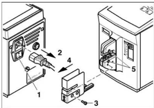
WARNING: Risk of injury

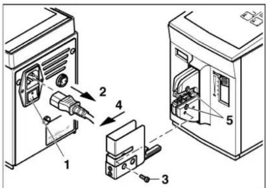
Switch off the CF 500 via the mains switch and disconnect the mains plug.

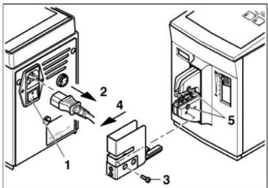
  • Switch off the CF 500 with the mains switch (1) (press 0).
  • Disconnect the mains plug (2).
    • Pull out the fuse holder (3).
  • Check the mains fuses (4).
  • Replace the blown mains fuse (for Order No. see ordering data on page 19).
  • Insert the fuse holder..

Phoenix Contact CF 500-230V - WARNING: Risk of injury - 1

NOTE: The fuse holder must snap into place.

A Appendix

A 1 Ordering data

Electric crimper

Description TypeOrder No.
Electric crimper 230 V CF 500-230V 1208348
Electric crimper 120 V CF 500-120V 1208351
Mains fuse for CF 500-230V FUSE SB 1.25 A 1208801
Mains fuse for CF 500-120VFUSE SB 2.5 A1209062

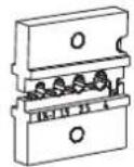
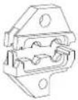
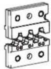
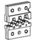
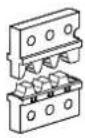
Crimping dies and protective covers

CF 500/DIE AI 6Order No. 1212238CF 500/COV AI 6Order No. 1212254CF 500/DIE AI 25Order No. 1212239CF 500/COV ^1 Order No. 1212250
Phoenix Contact CF 500-230V - A 1 Ordering data - 1Phoenix Contact CF 500-230V - A 1 Ordering data - 2Phoenix Contact CF 500-230V - A 1 Ordering data - 3Phoenix Contact CF 500-230V - A 1 Ordering data - 4 Phoenix Contact CF 500-230V - A 1 Ordering data - 5 Phoenix Contact CF 500-230V - A 1 Ordering data - 6
For ferrules (A... and AI...), 0.25 ... 6 mm ^2 For ferrules (A... and AI...), 10, 16, and 25 mm ^2
CF 500/DIE AI 50 CF 500/COVOrder No. 1212261CF 500/COV ^1 Order No. 1212250CF 500/DIE AI-TWIN 10Order No. 1212262CF 500/COV AI-TWINOrder No. 1212266
Phoenix Contact CF 500-230V - A 1 Ordering data - 7Phoenix Contact CF 500-230V - A 1 Ordering data - 8Phoenix Contact CF 500-230V - A 1 Ordering data - 9Phoenix Contact CF 500-230V - A 1 Ordering data - 10 Phoenix Contact CF 500-230V - A 1 Ordering data - 11 Phoenix Contact CF 500-230V - A 1 Ordering data - 12
For ferrules (A... and AI...), 35 and 50 mm ^2 For TWIN ferrules (AI-TWIN), 2 x 4, 2 x 6, and 2 x 10 mm ^2
CF 500/DIE TC 4Order No. 1212237CF 500/COV ^1 Order No. 1212250CF 500/DIE TC 10Order No. 1212260CF 500/COV ^1 Order No. 1212250
Phoenix Contact CF 500-230V - A 1 Ordering data - 13Phoenix Contact CF 500-230V - A 1 Ordering data - 14Phoenix Contact CF 500-230V - A 1 Ordering data - 15Phoenix Contact CF 500-230V - A 1 Ordering data - 16 Phoenix Contact CF 500-230V - A 1 Ordering data - 17 Phoenix Contact CF 500-230V - A 1 Ordering data - 18
For turned contacts (CK...), 0.14 ... 4 mm ^2 For turned contacts (CK...), 6 ... 10 mm ^2
CF 500/DIE SC 1,5Order No. 1212241CF 500/COV SCOrder No. 1212251CF 500/DIE SC 6Order No. 1212242CF 500/COV SCOrder No. 1212251
Phoenix Contact CF 500-230V - A 1 Ordering data - 19Phoenix Contact CF 500-230V - A 1 Ordering data - 20Phoenix Contact CF 500-230V - A 1 Ordering data - 21Phoenix Contact CF 500-230V - A 1 Ordering data - 22 Phoenix Contact CF 500-230V - A 1 Ordering data - 23 Phoenix Contact CF 500-230V - A 1 Ordering data - 24
For slip-on sleeves and flat plugs (SCF..., SCM...),0.1 ... 1.5 mm ^2 For slip-on sleeves and flat plugs (SCF..., SCM...),0.5 ... 6 mm ^2
CF 500/DIE RCI 6 CF 500/COV RCI Order No. 1212240 Order No. 1212255 Order No. 1212263 Phoenix Contact CF 500-230V - A 1 Ordering data - 25 Phoenix Contact CF 500-230V - A 1 Ordering data - 26 Phoenix Contact CF 500-230V - A 1 Ordering data - 27 For insulated cable lugs (RCI, FCI,...), 0.5 ... 6 mm2 For insulated cable lugs (RCI, FCI,...), 0.14 ... 1.0 mm2CF 500/DIE RCI 1,5 Order No. 1212255 Phoenix Contact CF 500-230V - A 1 Ordering data - 28 Phoenix Contact CF 500-230V - A 1 Ordering data - 29 Phoenix Contact CF 500-230V - A 1 Ordering data - 30CF 500/COV RCI
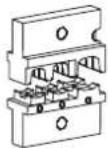
CF 500/DIE RCI 6-1 CF 500/COV RCI Order No. 1212691 Order No. 1212255 Order No. 1212692 Phoenix Contact CF 500-230V - A 1 Ordering data - 31 Phoenix Contact CF 500-230V - A 1 Ordering data - 32 Phoenix Contact CF 500-230V - A 1 Ordering data - 33 For insulated cable lugs (C-RCI, C-FCI) 0.5 ... 6 mm2, asymmetrical crimp shape, also suitable for insulated slip-on sleeves with metallic insulation supportCF 500/DIE SR 6-2 Order No. 1212255 Phoenix Contact CF 500-230V - A 1 Ordering data - 34 Phoenix Contact CF 500-230V - A 1 Ordering data - 35 For solar contacts 2.5 ... 6 mm2CF 500/COV RCI
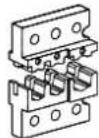
CF 500/DIE RC 10 CF 500/COV RC 10 Order No. 1212244 Order No. 1212252 Order No. 1212257 Phoenix Contact CF 500-230V - A 1 Ordering data - 36 Phoenix Contact CF 500-230V - A 1 Ordering data - 37 Phoenix Contact CF 500-230V - A 1 Ordering data - 38 For cable lugs according to DIN 46234 (RC, FC,...), 0.5 ... 10 mm2CF 500/DIE RC 16 Order No. 1212250 Phoenix Contact CF 500-230V - A 1 Ordering data - 39 Phoenix Contact CF 500-230V - A 1 Ordering data - 40 For cable lugs according to DIN 46234, (RC, FC,...), 16 mm2CF 500/COV1
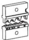
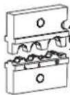
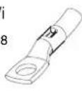
CF 500/DIE RCT 2,5 CF 500/COV RCT 2,5 Order No. 1212243 Order No. 1212253 Order No. 1212245 Phoenix Contact CF 500-230V - A 1 Ordering data - 41 Phoenix Contact CF 500-230V - A 1 Ordering data - 42 Phoenix Contact CF 500-230V - A 1 Ordering data - 43 For tube lugs, 0.34 ... 2.5 mm2CF 500/DIE RCT 10-1 2) 4 mm2 5/3 6 mm2 6.5 10 mm2 7/4 Phoenix Contact CF 500-230V - A 1 Ordering data - 44 For tube lugs (standard), 4 ... 10 mm2CF 500/COV RC 10 Order No. 1212252 Phoenix Contact CF 500-230V - A 1 Ordering data - 45 Phoenix Contact CF 500-230V - A 1 Ordering data - 46
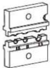
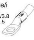
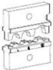
CF 500/DIE RCT 10-2 CF 500/COV RC 10 Order No. 12122462) Order No. 1212252 Order No. 1212256 Phoenix Contact CF 500-230V - A 1 Ordering data - 47 ∅ e/ 4 mm2 5/3 3 mm2 5.5/3. 10 mm2 6/4.5 Phoenix Contact CF 500-230V - A 1 Ordering data - 48 Phoenix Contact CF 500-230V - A 1 Ordering data - 49 For tube lugs according to DIN 46235, 4 ... 10 mm2CF 500/DIE RCT 10-3 2) Order No. 1212250 ∅ ε 4 mm2 5/3 6 mm2 6/4 Phoenix Contact CF 500-230V - A 1 Ordering data - 50 10 mm2 8/5 Phoenix Contact CF 500-230V - A 1 Ordering data - 51 For tube lugs (special), 4 ... 10 mm2CF 500/COV1
1) CF 500 - Protective cover without recess
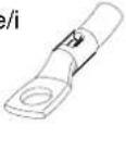
2) ∅ e/i (external/internal diameter, in millimeters), in relation to the cross section of the cable lug

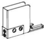
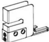
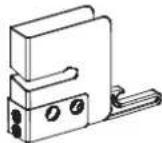
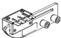
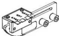
Locator for slip-on sleeves and flat plugs

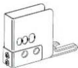
For precise crimping, a moveable locator, which precisely positions the contacts under the crimping stamp, can be fitted.
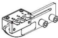
Phoenix Contact CF 500-230V - Locator for slip-on sleeves and flat plugs - 1

TypeOrderNo.Crimp contacts Die Protectivecover
CF 500/LOC SCF6,3/61212247Slip-on sleeves(SCF...) up to 6.3 mm wideCF 500/DIE SC 6 CF 500/COV SC

Phoenix Contact CF 500-230V - Locator for slip-on sleeves and flat plugs - 2

CF 500/LOC SCF4,8/2,51212248Slip-on sleeves(SCF...) up to 4.8 mm wideCF 500/DIE SC 1,5CF 500/DIE SC 6CF 500/COV SC
CF 500/LOC SCF2,8/1,51212249Slip-on sleeves(SCF...) up to 2.8 mm wide and 5 mm longCF 500/DIE SC 1,5CF 500/DIE SC 6CF 500/COV SC

Phoenix Contact CF 500-230V - Locator for slip-on sleeves and flat plugs - 3

Phoenix Contact CF 500-230V - Locator for slip-on sleeves and flat plugs - 4

Phoenix Contact CF 500-230V - Locator for slip-on sleeves and flat plugs - 5

CF 500/LOC SCM6,3/2,51212264 Flat plug (SCM...),0.5 ... 2.5 mm^2 CF 500/DIE SC 1,5CF 500/DIE SC 6CF 500/COV SC
CF 500/LOC SCM6,3/61212265 Flat plug (SCM...),1.5 ... 6 mm^2 CF 500/DIE SC 1,5CF 500/DIE SC 6CF 500/COV SC

A 2 Technical data

Technical data
Mains connection
CF 500-230V230 V/50 Hz
CF 500-120V120 V/60 Hz
Power consumption 160 VA
Maximum press capacity 10 kN
Press time< 1 s
Counter6-digit LCD, can be reset
Dimensions (W x H x D)140 mm x 220 mm x 320 mm
Weight of basic device10 kg
Weight of foot pedal1.2 kg
text_image Technical diagram showing labeled components of an electrical device, including a control box, cable, and clamp.

1 Appareil de base CF 500

text_image Technical diagram of a device with numbered components, showing front, side, and top views of the internal structure.
natural_image Line drawing of a rectangular electronic device with internal components and a top panel (no text or symbols)
Phoenix Contact CF 500-230V - A 2 Technical data - 1

text_image Technical diagram showing a device with labeled parts, including a switch and a bracket assembly.
text_image Technical diagram of a refrigerator interior with labeled parts and directional arrows indicating movement or assembly.

Phoenix Contact CF 500-230V - A 2 Technical data - 2

text_image Technical diagram showing a device with two labeled parts (1 and 2) connected to an open electrical box, likely illustrating a mechanical or electrical assembly.

Phoenix Contact CF 500-230V - A 2 Technical data - 3

text_image Technical diagram showing labeled components of an electrical device with numbered parts and wiring connections
text_image Technical diagram of an electrical enclosure with labeled components and wiring, showing internal structure and mounting details.

Phoenix Contact CF 500-230V - A 2 Technical data - 4

text_image Technical diagram showing exploded view of a computer case with labeled components and numbered parts
text_image Technical diagram of an electrical switchgear assembly with numbered components and exploded view

Phoenix Contact CF 500-230V - A 2 Technical data - 5

text_image Technical diagram showing a device with labeled parts and a vertical scale bar on the left.

Phoenix Contact CF 500-230V - A 2 Technical data - 6

natural_image Technical line drawing of a mechanical device with labeled components and an orange panel on the left (no text or symbols present)
text_image Technical diagram of a device with numbered components, showing front and side views of a device casing.

Phoenix Contact CF 500-230V - A 2 Technical data - 7

text_image Technical diagram of a device with numbered components and directional arrows indicating assembly or movement.

Phoenix Contact CF 500-230V - A 2 Technical data - 8

text_image Technical diagram of two electronic devices with labeled components, showing internal wiring and mounting parts.
text_image Technical diagram of a device with numbered components, showing front and side views of a box-like device.

Phoenix Contact CF 500-230V - A 2 Technical data - 9

text_image Technical diagram showing mechanical assembly with numbered components and directional arrows indicating assembly steps

Phoenix Contact CF 500-230V - A 2 Technical data - 10

text_image Technical diagram showing labeled mechanical components with numbered parts and directional arrows indicating assembly or assembly.

Phoenix Contact CF 500-230V - A 2 Technical data - 11

text_image Technical diagram of two electronic devices with labeled parts, showing internal components and mounting points.
natural_image Line drawing of a door with internal components, no text or symbols present

Phoenix Contact CF 500-230V - A 2 Technical data - 12

text_image Technical diagram showing installation steps of an electrical switch or fuse device with labeled components
text_image Technical diagram showing exploded view of a power connector with labeled parts including socket, plug, and socket terminal.

A Annexe

A 1 Références

text_image Technical diagram showing labeled components of an electrical device, including a control box, cable, and clamp.

1 Apparecchio base CF 500

text_image Technical diagram of a device with numbered components, likely an electrical or mechanical assembly.

Phoenix Contact CF 500-230V - A 1 Références - 1

text_image Technical diagram of a microwave oven with numbered parts labeled 6, 7, 8, 9, and 10

Phoenix Contact CF 500-230V - A 1 Références - 2

natural_image Technical line drawing of a mechanical clamp or bracket assembly (no text or symbols)
natural_image Line drawing of a rectangular electronic device with internal components and mounting brackets (no text or symbols)

Phoenix Contact CF 500-230V - A 1 Références - 3

text_image Technical diagram showing a device with labeled parts and directional arrows indicating assembly or installation steps.
text_image Technical diagram of a refrigerator interior with labeled parts and directional arrows indicating movement or assembly.

Phoenix Contact CF 500-230V - A 1 Références - 4

text_image Technical diagram showing a device with two labeled parts and an open electrical enclosure, illustrating assembly or installation steps.

Phoenix Contact CF 500-230V - A 1 Références - 5

text_image Technical diagram showing labeled components of an electrical device with numbered parts and wiring connections
text_image Technical diagram of an electrical enclosure with labeled components and wiring, showing internal structure and mounting details.

Phoenix Contact CF 500-230V - A 1 Références - 6

text_image Technical diagram showing exploded view of a computer case with labeled components and numbered parts
text_image Technical diagram of an electrical switchgear assembly with numbered components and exploded view

Phoenix Contact CF 500-230V - A 1 Références - 7

text_image Technical diagram showing a device with labeled components and a vertical scale bar on the left.

Phoenix Contact CF 500-230V - A 1 Références - 8

natural_image Technical line drawing of a device with labeled components and an orange panel on the left (no text or symbols present)
text_image Technical diagram of a device with numbered components, showing front and side views of a device casing.

Phoenix Contact CF 500-230V - A 1 Références - 9

text_image Technical diagram of a device with numbered components and directional arrows indicating assembly or movement.

Phoenix Contact CF 500-230V - A 1 Références - 10

text_image Technical diagram of two electronic devices with labeled components, showing internal wiring and mounting parts.
text_image Technical diagram of a device with numbered components, showing front and side views of a box-like device.

Phoenix Contact CF 500-230V - A 1 Références - 11

text_image Technical diagram showing a device with labeled parts and directional arrows indicating assembly or movement.
text_image Technical diagram showing labeled mechanical components with numbered parts and directional arrows indicating assembly or assembly.
text_image Technical diagram of two electronic devices with labeled components, showing internal wiring and mounting parts.
natural_image Line drawing of a refrigerator with an open door and internal compartments (no text or symbols)

Phoenix Contact CF 500-230V - A 1 Références - 12

text_image Diagram showing installation steps of an electronic device with labeled components and connectors
text_image Technical diagram showing exploded view of a power connector with labeled parts including socket, plug, and connectors

A Appendice

- P u n t e r a s T W I N

text_image Technical diagram showing labeled components of an electrical device, including a control box, cable, and motor assembly.
text_image Technical diagram of an electrical enclosure with numbered components for identification

Phoenix Contact CF 500-230V - A Appendice - 1

text_image Technical diagram of a device with numbered parts labeled 6, 7, 8, 9, and 10

Phoenix Contact CF 500-230V - A Appendice - 2

natural_image Technical line drawing of a mechanical clamp or bracket component (no text or symbols)
natural_image Line drawing of a rectangular electronic device with a lid and internal components (no text or symbols)

Phoenix Contact CF 500-230V - A Appendice - 3

text_image Technical diagram showing a device with labeled parts, including a switch and a bracket assembly.

Emplazar la CF 500

Phoenix Contact CF 500-230V - Emplazar la CF 500 - 1

text_image Technical diagram of a refrigerator interior with labeled parts and directional arrows indicating movement or assembly.

Phoenix Contact CF 500-230V - Emplazar la CF 500 - 2

text_image Technical diagram showing a device with two labeled parts and an open electrical enclosure, illustrating assembly or installation steps.

Phoenix Contact CF 500-230V - Emplazar la CF 500 - 3

text_image Technical diagram showing labeled components of an electrical device with numbered parts and wiring connections
text_image Technical diagram of an electrical enclosure with labeled components and wiring, showing internal structure and mounting details.

Phoenix Contact CF 500-230V - Emplazar la CF 500 - 4

text_image Technical diagram showing exploded view of a computer case with labeled components and numbered parts
text_image Technical diagram of an electrical switchgear assembly with numbered components and exploded view

Phoenix Contact CF 500-230V - Emplazar la CF 500 - 5

text_image Technical diagram showing a control panel with labeled components and a vertical scale bar on the left.

Phoenix Contact CF 500-230V - Emplazar la CF 500 - 6

natural_image Technical line drawing of a device with labeled components and an orange panel on the left (no text or symbols present)
text_image Technical diagram of a device with numbered components, showing front and side views of a device casing.

Phoenix Contact CF 500-230V - Emplazar la CF 500 - 7

Ajuste del modo operativo 1

text_image Technical diagram showing labeled mechanical components with numbered parts and directional arrows indicating assembly or assembly.

Phoenix Contact CF 500-230V - Ajuste del modo operativo 1 - 1

text_image Technical diagram of two electronic device boxes with labeled components, showing internal wiring and mounting parts.
text_image Technical diagram of a device with numbered components, showing front and side views of a box-like device.

Phoenix Contact CF 500-230V - Ajuste del modo operativo 1 - 2

Ajuste del modo operativo 2

text_image Technical diagram showing a device with labeled parts and directional arrows indicating assembly or movement.
text_image Technical diagram showing labeled mechanical components with numbered parts and directional arrows indicating assembly or assembly.
text_image Technical diagram of two electronic devices with labeled components, showing internal wiring and mounting parts.
natural_image Line drawing of a refrigerator with an open door and internal compartments (no text or symbols)

Phoenix Contact CF 500-230V - Ajuste del modo operativo 2 - 1

Matrices de engaste mal ajustadas

Phoenix Contact CF 500-230V - Matrices de engaste mal ajustadas - 1

Phoenix Contact CF 500-230V - Matrices de engaste mal ajustadas - 2

text_image Technical diagram showing installation steps of an electronic device with labeled components
text_image Technical diagram showing exploded view of a power connector with labeled parts including socket, plug, and connectors

A Anexo

A 1 Datos de pedido

text_image Technical diagram showing labeled components of an electrical device, including a control box, cable, and motor.
text_image Technical diagram of a device with numbered components, likely an electrical or mechanical assembly.

Phoenix Contact CF 500-230V - A 1 Datos de pedido - 1

text_image Technical diagram of a device with numbered parts labeled 6, 7, 8, 9, and 10

Phoenix Contact CF 500-230V - A 1 Datos de pedido - 2

natural_image Technical line drawing of a mechanical clamp or bracket component (no text or symbols)
natural_image Line drawing of a rectangular electronic device with internal components and mounting brackets (no text or symbols)

Phoenix Contact CF 500-230V - A 1 Datos de pedido - 3

text_image Technical diagram showing a device with labeled parts, including a switch and a bracket assembly.

Instalar o CF 500

Phoenix Contact CF 500-230V - Instalar o CF 500 - 1

text_image Technical diagram of a refrigerator interior with labeled parts and directional arrows indicating movement or assembly.

Phoenix Contact CF 500-230V - Instalar o CF 500 - 2

text_image Technical diagram showing a device with two labeled parts and an open electrical enclosure, illustrating assembly or installation steps.

Phoenix Contact CF 500-230V - Instalar o CF 500 - 3

text_image Technical diagram showing labeled components of an electrical device with numbered parts and wiring connections
text_image Technical diagram of an electrical switch device with numbered components and labeled parts

Phoenix Contact CF 500-230V - Instalar o CF 500 - 4

text_image Technical diagram showing exploded view of a computer case with labeled components and numbered parts
text_image Technical diagram of an electrical switchgear assembly with numbered components and exploded view

Phoenix Contact CF 500-230V - Instalar o CF 500 - 5

text_image Technical diagram showing a control panel with labeled components and an open device labeled '1'

Phoenix Contact CF 500-230V - Instalar o CF 500 - 6

natural_image Technical line drawing of a mechanical device with labeled components and an inset showing a rectangular component (no text or symbols present)
text_image Technical diagram of a device with numbered components, showing front and side views of a device casing.

Phoenix Contact CF 500-230V - Instalar o CF 500 - 7

text_image Technical diagram of a device with numbered components and directional arrows indicating assembly or movement.

Phoenix Contact CF 500-230V - Instalar o CF 500 - 8

text_image Technical diagram of two electronic device boxes with labeled components, showing internal components and mounting points.
text_image Technical diagram of a device with numbered components, showing front and side views of a box-like device.

Phoenix Contact CF 500-230V - Instalar o CF 500 - 9

text_image Technical diagram showing mechanical assembly with numbered components and directional arrows indicating assembly steps

Phoenix Contact CF 500-230V - Instalar o CF 500 - 10

text_image Technical diagram showing labeled mechanical components with numbered parts and directional arrows indicating assembly or assembly.

Phoenix Contact CF 500-230V - Instalar o CF 500 - 11

text_image Technical diagram of two electronic devices with labeled parts, showing internal components and mounting points.
natural_image Line drawing of a refrigerator with open door and internal compartments (no text or symbols)

error

Phoenix Contact CF 500-230V - error - 1

Phoenix Contact CF 500-230V - error - 2

text_image Diagram showing electrical switch installation steps with labeled components 1 to 5
text_image Technical diagram showing exploded view of electrical connectors and components with numbered labels

A Anexo

text_image Technical diagram showing labeled components of an electrical device, including a control box, coiled cable, and motor.
text_image Technical diagram of an electrical device with numbered components for identification

Phoenix Contact CF 500-230V - A Anexo - 1

text_image Technical diagram of a device with numbered parts labeled 6, 7, 8, 9, and 10

Phoenix Contact CF 500-230V - A Anexo - 2

natural_image Technical line drawing of a mechanical clamp or bracket component (no text or symbols)
natural_image Line drawing of a rectangular electronic device with a lid and internal ports (no text or symbols)

Phoenix Contact CF 500-230V - A Anexo - 3

text_image Technical diagram showing a mechanical assembly with labeled parts, including a component labeled '1' and part numbers 2.

CF 500kurun

Phoenix Contact CF 500-230V - CF 500kurun - 1

text_image Technical diagram of a refrigerator interior with labeled parts and directional arrows indicating movement or assembly.

Phoenix Contact CF 500-230V - CF 500kurun - 2

text_image Technical diagram showing a device with two labeled parts and an open electrical box, illustrating assembly or installation steps.

Phoenix Contact CF 500-230V - CF 500kurun - 3

text_image Technical diagram showing labeled components of an electrical device with numbered parts and wiring connections

Kivirma kalibini monte edin

Phoenix Contact CF 500-230V - Kivirma kalibini monte edin - 1

text_image Technical diagram of an electrical switch device with numbered components and labeled parts

Phoenix Contact CF 500-230V - Kivirma kalibini monte edin - 2

text_image Technical diagram showing exploded view of a computer case with labeled components and numbered parts
text_image Technical diagram of an electrical switchgear assembly with numbered components and exploded view

Phoenix Contact CF 500-230V - Kivirma kalibini monte edin - 3

text_image Technical diagram showing a device with labeled parts and a scale bar, alongside its exploded view.

Phoenix Contact CF 500-230V - Kivirma kalibini monte edin - 4

natural_image Technical line drawing of a mechanical device with labeled components and an orange panel on the left (no text or symbols present)
text_image Technical diagram of a device with numbered components, showing front and side views of a device casing.

Phoenix Contact CF 500-230V - Kivirma kalibini monte edin - 5

text_image Technical diagram of a device with numbered components and directional arrows indicating assembly or movement.

Phoenix Contact CF 500-230V - Kivirma kalibini monte edin - 6

text_image Technical diagram of two electronic devices with labeled components, showing internal wiring and mounting parts.

Kivirma kontaklarını kivirma

text_image Technical diagram of a device with numbered components, showing front and side views of a box-like device.

Phoenix Contact CF 500-230V - Kivirma kontaklarını kivirma - 1

text_image Technical diagram showing labeled mechanical components with numbered parts and directional arrows indicating assembly or assembly.

Phoenix Contact CF 500-230V - Kivirma kontaklarını kivirma - 2

text_image Technical diagram showing labeled mechanical components with numbered parts and directional arrows indicating assembly or assembly.

Phoenix Contact CF 500-230V - Kivirma kontaklarını kivirma - 3

text_image Technical diagram of two electronic devices with labeled parts, showing internal components and mounting points.
natural_image Line drawing of a refrigerator with an open door and internal compartments (no text or symbols)

Phoenix Contact CF 500-230V - Kivirma kontaklarını kivirma - 4

text_image Diagram showing installation steps of an electronic device with labeled components 1 through 5
text_image Technical diagram showing exploded view of a power connector with labeled parts including socket, plug, and socket terminal.
text_image Technical diagram showing labeled components of an electrical device, including a control box, cable, and clamp.
text_image Technical diagram of a device with numbered components, showing front, side, and top views of the internal structure.
natural_image Line drawing of a rectangular electronic device with a lid and internal components (no text or symbols)

Phoenix Contact CF 500-230V - Kivirma kontaklarını kivirma - 5

text_image Technical diagram showing a device with labeled parts and directional arrows indicating assembly or installation steps.

Установить CF 500

Phoenix Contact CF 500-230V - Установить CF 500 - 1

text_image Technical diagram of a refrigerator interior with labeled parts and directional arrows indicating movement or assembly.

Phoenix Contact CF 500-230V - Установить CF 500 - 2

text_image Technical diagram showing a device with two labeled parts and an open electrical enclosure, illustrating assembly or installation steps.

Phoenix Contact CF 500-230V - Установить CF 500 - 3

text_image Technical diagram showing labeled components of an electrical device with numbered parts and wiring connections

Установить матрицу

Phoenix Contact CF 500-230V - Установить матрицу - 1

text_image Technical diagram of an electrical enclosure with labeled components and wiring connections

Phoenix Contact CF 500-230V - Установить матрицу - 2

text_image Technical diagram showing exploded view of a computer case with labeled components and numbered parts
text_image Technical diagram of an electrical switchgear assembly with numbered components and exploded view

Phoenix Contact CF 500-230V - Установить матрицу - 3

text_image Technical diagram showing a control panel with labeled components and a vertical scale on the left.

Phoenix Contact CF 500-230V - Установить матрицу - 4

natural_image Technical line drawing of a mechanical device with labeled components and an orange panel on the left (no text or symbols present)
text_image Technical diagram of a device with numbered components, showing front and side views of a device casing.

Phoenix Contact CF 500-230V - Установить матрицу - 5

text_image Technical diagram showing labeled mechanical components with numbered parts and directional arrows indicating assembly or assembly.

Phoenix Contact CF 500-230V - Установить матрицу - 6

natural_image Technical line drawing of two open industrial equipment units (no text or symbols)

Обжать контакт

text_image Technical diagram of a device with numbered components, showing front and side views of a device casing.

Phoenix Contact CF 500-230V - Обжать контакт - 1

text_image Technical diagram showing a device assembly with numbered components and directional arrows indicating assembly steps.
text_image Technical diagram showing labeled mechanical components with numbered parts and directional arrows indicating assembly or assembly.

Обжать контакт

natural_image Technical line drawing of two electronic devices with labeled parts (no text or symbols present)

Phoenix Contact CF 500-230V - Обжать контакт - 1

natural_image Line drawing of a refrigerator with open door and internal compartments (no text or symbols)

Phoenix Contact CF 500-230V - Обжать контакт - 2

text_image Technical diagram showing component assembly with numbered parts for installation or repair
text_image Technical diagram showing exploded view of a power connector with labeled parts including socket, plug, and connectors

А Приложение

text_image Technical diagram showing labeled components of an electrical device, including a control box, cable, and motor.
text_image Technical diagram of an electronic device with numbered components for identification

Phoenix Contact CF 500-230V - А Приложение - 1

text_image Technical diagram of a device with numbered parts labeled 6, 7, 8, 9, and 10

Phoenix Contact CF 500-230V - А Приложение - 2

natural_image Technical line drawing of a mechanical clamp or bracket component (no text or symbols)
natural_image Line drawing of a rectangular electronic device with a lid and internal components (no text or symbols)

Phoenix Contact CF 500-230V - А Приложение - 3

text_image Technical diagram showing a device with labeled parts, including a switch and a bracket assembly.
text_image Technical diagram of a refrigerator interior with labeled parts and directional arrows indicating movement or assembly.

Phoenix Contact CF 500-230V - А Приложение - 4

text_image Technical diagram showing a device with two labeled parts and an open electrical box, illustrating assembly or installation steps.

Phoenix Contact CF 500-230V - А Приложение - 5

text_image Technical diagram showing labeled components of an electrical device with numbered parts and wiring connections
text_image Technical diagram of an electrical switch device with numbered components and labeled parts

Phoenix Contact CF 500-230V - А Приложение - 6

text_image Technical diagram showing exploded view of a computer case with labeled components and numbered parts
text_image Technical diagram of an electrical switchgear assembly with numbered components and exploded view

Phoenix Contact CF 500-230V - А Приложение - 7

text_image Technical diagram showing a device with labeled parts and a vertical scale bar, alongside its exploded view.

Phoenix Contact CF 500-230V - А Приложение - 8

natural_image Technical line drawing of a mechanical device with labeled components and an orange panel on the left (no text or symbols present)
text_image Technical diagram of a device with numbered components, showing front and side views of a device casing.

Phoenix Contact CF 500-230V - А Приложение - 9

text_image Technical diagram of a device with numbered components and directional arrows indicating assembly or assembly steps.

Phoenix Contact CF 500-230V - А Приложение - 10

text_image Technical diagram of two electronic devices with labeled parts, showing internal components and mounting points.
text_image Technical diagram of a device with numbered components, showing front and side views of a device casing.

Phoenix Contact CF 500-230V - А Приложение - 11

text_image Technical diagram showing a device with labeled parts and directional arrows indicating assembly or movement.

Phoenix Contact CF 500-230V - А Приложение - 12

text_image Technical diagram showing labeled mechanical components with numbered parts and directional arrows indicating assembly or assembly.

Phoenix Contact CF 500-230V - А Приложение - 13

natural_image Technical line drawing of two electronic devices with labeled parts (no text or symbols present)
natural_image Line drawing of a refrigerator with an open door and internal compartments (no text or symbols)

Phoenix Contact CF 500-230V - А Приложение - 14

Phoenix Contact CF 500-230V - А Приложение - 15

Phoenix Contact CF 500-230V - А Приложение - 16

text_image Diagram showing installation steps of an electrical switch or fuse, labeled with components 1 through 5.
text_image Technical diagram showing exploded view of a power connector with labeled parts including socket, plug, and socket terminal.

Α Παράρτημα

phoenixcontact.net/products.

Filialer i de enkelte lande

text_image Technical diagram showing labeled components of an electrical device, including a control box, coiled cable, and motor.

1 Basisapparat CF 500

text_image Technical diagram of an electrical enclosure with numbered components for identification

Phoenix Contact CF 500-230V - Filialer i de enkelte lande - 1

text_image Technical diagram of a device with numbered parts labeled 6, 7, 8, 9, and 10

Phoenix Contact CF 500-230V - Filialer i de enkelte lande - 2

natural_image Technical line drawing of a mechanical clamp or bracket component (no text or symbols)
natural_image Line drawing of a rectangular electronic device with a lid and internal ports (no text or symbols)

Phoenix Contact CF 500-230V - Filialer i de enkelte lande - 3

text_image Technical diagram showing a mechanical assembly with labeled parts and directional arrows indicating movement or assembly.

CF 500 opstilling

Phoenix Contact CF 500-230V - CF 500 opstilling - 1

text_image Technical diagram of a refrigerator interior with labeled parts and directional arrows indicating movement or assembly.

Phoenix Contact CF 500-230V - CF 500 opstilling - 2

text_image Technical diagram showing a device with two labeled parts: one inserted into a housing and the other attached to an open electrical cabinet.

Phoenix Contact CF 500-230V - CF 500 opstilling - 3

text_image Technical diagram showing labeled components of an electrical device with numbered parts and wiring connections
text_image Technical diagram of an electrical switch device with numbered components and labeled parts

Phoenix Contact CF 500-230V - CF 500 opstilling - 4

text_image Technical diagram showing exploded view of a computer case with labeled components and numbered parts
text_image Technical diagram of an electrical switchgear assembly with numbered components and exploded view

Phoenix Contact CF 500-230V - CF 500 opstilling - 5

text_image Technical diagram showing a control panel with labeled components and an exploded view of the device interior.

Phoenix Contact CF 500-230V - CF 500 opstilling - 6

natural_image Technical line drawing of a mechanical device with a control panel and orange panel, no text or symbols present.
text_image Technical diagram of a device with numbered components, showing front and side views of a device casing.

Phoenix Contact CF 500-230V - CF 500 opstilling - 7

text_image Technical diagram of a device with numbered components and directional arrows indicating assembly or movement.

Phoenix Contact CF 500-230V - CF 500 opstilling - 8

text_image Technical diagram of two electronic devices with labeled components, showing internal wiring and mounting parts.
text_image Technical diagram of a device with numbered components, showing front and side views of a box-like device.

Phoenix Contact CF 500-230V - CF 500 opstilling - 9

Indstil driftsform 2

text_image Technical diagram showing mechanical assembly with numbered components and directional arrows indicating assembly steps

Phoenix Contact CF 500-230V - Indstil driftsform 2 - 1

text_image Technical diagram showing labeled mechanical components with numbered parts and directional arrows indicating assembly or assembly.

Phoenix Contact CF 500-230V - Indstil driftsform 2 - 2

text_image Technical diagram of two electronic devices with labeled parts, showing internal components and mounting points.

Klem krympekontakten fast

Phoenix Contact CF 500-230V - Klem krympekontakten fast - 1

natural_image Line drawing of a refrigerator with an open door and internal compartments (no text or symbols)

Phoenix Contact CF 500-230V - Klem krympekontakten fast - 2

Phoenix Contact CF 500-230V - Klem krympekontakten fast - 3

text_image Technical diagram showing component assembly steps with numbered labels for installation or repair instructions
text_image Technical diagram showing exploded view of a power connector with labeled parts including socket, plug, and connectors

A Bilag

A 1 Bestillingsdata

Elektrisk krympetang

Beskrivelse TypeBestill.nr.
Elektrisk krympetang 230 V CF 500-230V 1208348
Elektrisk krympetang 120 V CF 500-120V 1208351
Netsikring til CF 500-230V FUSE SB 1,25 A 1208801
Netsikring til CF 500-120VFUSE SB 2,5 A1209062
text_image Technical diagram showing labeled components of an electrical device, including a control box, cable, and motor.

1 Basisapparaat CF 500

2 Beschermkap

3 Netkabel

4 Voetschakelaar

Handboek

text_image Technical diagram of a device with numbered components, likely an electrical or mechanical assembly.

Phoenix Contact CF 500-230V - A 1 Bestillingsdata - 1

text_image Technical diagram of a microwave oven with numbered parts labeled 6, 7, 8, 9, and 10

Phoenix Contact CF 500-230V - A 1 Bestillingsdata - 2

natural_image Technical line drawing of a mechanical clamp or bracket component (no text or symbols)
natural_image Line drawing of a rectangular electronic device with a lid and internal components (no text or symbols)

Phoenix Contact CF 500-230V - A 1 Bestillingsdata - 3

text_image Technical diagram showing a device with labeled components and directional arrows indicating assembly or installation steps.

CF 500 opstellen

Phoenix Contact CF 500-230V - CF 500 opstellen - 1

WAARSCHUWING: Letselgevaar!

text_image Technical diagram of a refrigerator interior with labeled parts and directional arrows indicating movement or assembly.

Phoenix Contact CF 500-230V - CF 500 opstellen - 2

text_image Technical diagram showing a device with two labeled parts and an open electrical box, illustrating assembly or installation steps.

Phoenix Contact CF 500-230V - CF 500 opstellen - 3

text_image Technical diagram of an electrical device with labeled components including a power box, transformer, and cable connections.

Crimpprofiel monteren

Phoenix Contact CF 500-230V - Crimpprofiel monteren - 1

text_image Technical diagram of an electrical enclosure with labeled components and wiring connections

Phoenix Contact CF 500-230V - Crimpprofiel monteren - 2

text_image Technical diagram showing exploded view and internal component assembly of a computer case with numbered parts

Crimpprofielen centreren

Phoenix Contact CF 500-230V - Crimpprofielen centreren - 1

WAARSCHUWING: Letselgevaar!

text_image Technical diagram of an electrical switchgear assembly with numbered components and exploded view

Phoenix Contact CF 500-230V - Crimpprofielen centreren - 2

text_image Technical diagram showing a device with labeled parts and a scale bar, alongside its exploded view.

Phoenix Contact CF 500-230V - Crimpprofielen centreren - 3

natural_image Technical line drawing of a mechanical device with labeled components and an orange panel on the left (no text or symbols present)

Optimale opening instellen

text_image Technical diagram of a device with numbered components, showing front and side views of a device casing.

Phoenix Contact CF 500-230V - Optimale opening instellen - 1

text_image Technical diagram of a device with numbered components and directional arrows indicating assembly or movement.

Phoenix Contact CF 500-230V - Optimale opening instellen - 2

text_image Technical diagram of two electronic devices with labeled components, showing internal wiring and mounting parts.

Crimpcontact krimpen

text_image Technical diagram of a device with numbered components, showing front and side views of a box-like device.

Phoenix Contact CF 500-230V - Crimpcontact krimpen - 1

text_image Technical diagram showing mechanical assembly with numbered components and directional arrows indicating assembly steps

Crimpcontact vastklemmen

Phoenix Contact CF 500-230V - Crimpcontact vastklemmen - 1

text_image Technical diagram showing labeled mechanical components with numbered parts and directional arrows indicating assembly or assembly.

Crimpcontact krimpen

text_image Technical diagram of two electronic devices with labeled parts, showing internal components and mounting points.

Uit bedrijf nemen

natural_image Line drawing of an open refrigerator with internal compartments (no text or symbols)

Phoenix Contact CF 500-230V - Uit bedrijf nemen - 1

WAARSCHUWING: Letselgevaar!

text_image Diagram showing installation steps of an electronic device with labeled components and connectors

WAARSCHUWING: Letselgevaar!

text_image Technical diagram showing exploded view of a power connector with labeled parts including socket, plug, and connectors

A Bijlage

A 1 Bestelgegevens

Elektrocrimper

text_image Technical diagram showing labeled components of an electrical device, including a control box, coiled cable, and motor.

1 Basisenhet CF 500

2 Beskyttelseshette

3 Strømkabel

4 Fotbryter

Brukerhändbok

2.2 Oversikt over betjeningsdelene

Phoenix Contact CF 500-230V - Oversikt over betjeningsdelene - 1

text_image Technical diagram of an electrical enclosure with numbered components for identification

Phoenix Contact CF 500-230V - Oversikt over betjeningsdelene - 2

text_image Technical diagram of a device with numbered parts labeled 6, 7, 8, 9, and 10

Phoenix Contact CF 500-230V - Oversikt over betjeningsdelene - 3

natural_image Technical line drawing of a mechanical clamp or bracket component (no text or symbols)
natural_image Line drawing of a rectangular electronic device with a lid and internal ports (no text or symbols)

Phoenix Contact CF 500-230V - Oversikt over betjeningsdelene - 4

text_image Technical diagram showing a mechanical assembly with labeled parts, including a component labeled '1' and part numbers 2.

Plassere CF 500

Phoenix Contact CF 500-230V - Plassere CF 500 - 1

text_image Technical diagram of a refrigerator interior with labeled parts and directional arrows indicating movement or assembly.

Phoenix Contact CF 500-230V - Plassere CF 500 - 2

text_image Technical diagram showing a device with two labeled parts and an open electrical enclosure, illustrating assembly or installation steps.

Phoenix Contact CF 500-230V - Plassere CF 500 - 3

text_image Technical diagram showing labeled components of an electrical device with numbered parts and wiring connections

Montere krympeinnsatsen

Phoenix Contact CF 500-230V - Montere krympeinnsatsen - 1

text_image Technical diagram of an electrical enclosure with labeled components and wiring connections

Phoenix Contact CF 500-230V - Montere krympeinnsatsen - 2

text_image Technical diagram showing installation steps of a computer case with labeled components and directional arrows
text_image Technical diagram of an electrical switchgear assembly with numbered components and exploded view

Phoenix Contact CF 500-230V - Montere krympeinnsatsen - 3

text_image Technical diagram showing a device with labeled components and a magnified view of its internal structure.

Phoenix Contact CF 500-230V - Montere krympeinnsatsen - 4

natural_image Technical line drawing of a device with labeled components and an orange panel on the left (no text or symbols present)
text_image Technical diagram of a device with numbered components, showing front and side views of a device casing.

Phoenix Contact CF 500-230V - Montere krympeinnsatsen - 5

Stille inn driftsmodus 1

  • Slå på CF 500 med strømbryteren (1) (trykk på l). Lysdioden „ready“ lyser (2).
  • Trykk på knappen „Driftsmodus 1“ (3).
  • Les av stykktelleren (4) ved behov og still den tilbake til 0 med knappen „reset“ (5).

Phoenix Contact CF 500-230V - Stille inn driftsmodus 1 - 1

text_image Technical diagram of a device with numbered components and directional arrows indicating assembly or movement.

Phoenix Contact CF 500-230V - Stille inn driftsmodus 1 - 2

text_image Technical diagram of two electronic devices with labeled components, showing internal wiring and mounting parts.

Krympe krympekontakt

  • Sentrer krympekontakten (1) på nederste krympeinnsats.
    • Legg lederen (2) inn i krympekontakten.

Phoenix Contact CF 500-230V - Krympe krympekontakt - 1

OBS: Sørg for riktig tverrsnitt.

text_image Technical diagram of a device with numbered components, showing front and side views of a device casing.

Phoenix Contact CF 500-230V - Krympe krympekontakt - 2

Stille inn driftsmodus 2

  • Slå på CF 500 med strømbryteren (1) (trykk på l). Lysdioden „ready“ lyser (2).
  • Trykk på knappen „Driftsmodus 2“ (3).
  • Les av stykktelleren (4) ved behov og still den tilbake til 0 med knappen „reset“ (5).

Phoenix Contact CF 500-230V - Stille inn driftsmodus 2 - 1

text_image Technical diagram showing a device with labeled parts and directional arrows indicating assembly or movement.

Phoenix Contact CF 500-230V - Stille inn driftsmodus 2 - 2

text_image Technical diagram showing labeled mechanical components with numbered parts and directional arrows indicating assembly or assembly.

Phoenix Contact CF 500-230V - Stille inn driftsmodus 2 - 3

text_image Technical diagram of two electronic devices with labeled parts, showing internal components and mounting points.

Klemme fast krympekontakt

Phoenix Contact CF 500-230V - Klemme fast krympekontakt - 1

OBS: Sørg for riktig tverrsnitt.

  • Sentrer krympekontakten (1) på nederste krympeinnsats.
  • Trykk på fotbryteren (2) til krympekontakten er klemt fast (3).
  • Slipp fotbryteren (4).

Krympe krympekontakt

natural_image Line drawing of a refrigerator with an open door and internal compartments (no text or symbols)

Phoenix Contact CF 500-230V - Krympe krympekontakt - 1

Phoenix Contact CF 500-230V - Krympe krympekontakt - 2

text_image Diagram showing component assembly of a device with labeled parts 1 to 5, including connectors and switches.
text_image Technical diagram showing exploded view of a power connector with labeled parts including socket, plug, and socket terminal.

Nettsikring defekt

Phoenix Contact CF 500-230V - Nettsikring defekt - 1

#Fare for personskader!

text_image Technical diagram showing labeled components of an electrical device, including a control box, coiled cable, and motor.

1 Basenhet CF 500

2 Skyddshuv

3 Elkabel

4 Fotomkopplare

Användarhandbok

text_image Technical diagram of an electrical enclosure with numbered components for identification

Phoenix Contact CF 500-230V - #Fare for personskader! - 1

text_image Technical diagram of a device with numbered parts labeled 6, 7, 8, 9, and 10

Phoenix Contact CF 500-230V - #Fare for personskader! - 2

natural_image Technical line drawing of a mechanical clamp or bracket component (no text or symbols)
natural_image Line drawing of a rectangular electronic device with a lid and internal ports (no text or symbols)

Phoenix Contact CF 500-230V - #Fare for personskader! - 3

text_image Technical diagram showing a mechanical assembly with labeled parts, including a component labeled '1' and part numbers 2.
text_image Technical diagram of a refrigerator interior with labeled parts and directional arrows indicating movement or assembly.

Phoenix Contact CF 500-230V - #Fare for personskader! - 4

text_image Technical diagram showing a device with two labeled parts: one inserted into a box and the other attached to a housing.

Phoenix Contact CF 500-230V - #Fare for personskader! - 5

text_image Technical diagram showing labeled components of an electrical device with numbered parts and wiring connections
text_image Technical diagram of an electrical switch device with numbered components and labeled parts

Phoenix Contact CF 500-230V - #Fare for personskader! - 6

text_image Technical diagram showing exploded view of a computer case with labeled components and numbered parts
text_image Technical diagram of an electrical switchgear assembly with numbered components and exploded view

Phoenix Contact CF 500-230V - #Fare for personskader! - 7

text_image Technical diagram showing a device with labeled components and a magnified view of its internal structure.

Phoenix Contact CF 500-230V - #Fare for personskader! - 8

natural_image Technical line drawing of a device with labeled components and an orange panel on the left (no text or symbols present)
text_image Technical diagram of a device with numbered components, showing front and side views of a device casing.

Phoenix Contact CF 500-230V - #Fare for personskader! - 9

text_image Technical diagram of a device with numbered components and directional arrows indicating assembly or movement.

Phoenix Contact CF 500-230V - #Fare for personskader! - 10

natural_image Technical line drawing of two electronic devices with labeled parts (no text or symbols present)
text_image Technical diagram of a device with numbered components, showing front and side views of a box-like device.

Phoenix Contact CF 500-230V - #Fare for personskader! - 11

text_image Technical diagram showing mechanical assembly with numbered components and directional arrows indicating assembly steps

Phoenix Contact CF 500-230V - #Fare for personskader! - 12

text_image Technical diagram showing labeled mechanical components with numbered parts and directional arrows indicating assembly or assembly.

Phoenix Contact CF 500-230V - #Fare for personskader! - 13

text_image Technical diagram of two electronic devices with labeled parts, showing internal components and mounting points.

Kläm fast crimpkontakten

Phoenix Contact CF 500-230V - Kläm fast crimpkontakten - 1

natural_image Line drawing of a refrigerator with an open door and internal compartments (no text or symbols)

Phoenix Contact CF 500-230V - Kläm fast crimpkontakten - 2

Phoenix Contact CF 500-230V - Kläm fast crimpkontakten - 3

Phoenix Contact CF 500-230V - Kläm fast crimpkontakten - 4

text_image Technical diagram showing installation steps of an electronic device with labeled components
text_image Technical diagram showing exploded view of a power connector with labeled parts including socket, plug, and socket terminal.

phoenixcontact.net/products.

text_image Technical diagram showing labeled components of an electrical device, including a control box, cable, and motor.
text_image Technical diagram of a device with numbered components, likely an electrical or mechanical assembly.

Phoenix Contact CF 500-230V - Kläm fast crimpkontakten - 5

text_image Technical diagram of a device with numbered parts labeled 6, 7, 8, 9, and 10

Phoenix Contact CF 500-230V - Kläm fast crimpkontakten - 6

natural_image Technical line drawing of a mechanical clamp or bracket component (no text or symbols)
natural_image Line drawing of a rectangular electronic device with a digital display and internal components (no text or symbols)

Phoenix Contact CF 500-230V - Kläm fast crimpkontakten - 7

text_image Technical diagram showing a device with labeled parts and directional arrows, likely illustrating a mounting or disassembly process.
text_image Technical diagram of a refrigerator interior with labeled parts and directional arrows indicating movement or assembly.

Phoenix Contact CF 500-230V - Kläm fast crimpkontakten - 8

text_image Technical diagram showing a device with two labeled parts and an open electrical enclosure, illustrating assembly or installation steps.

Phoenix Contact CF 500-230V - Kläm fast crimpkontakten - 9

text_image Technical diagram showing labeled components of an electrical device with numbered parts and wiring connections
text_image Technical diagram of an electrical enclosure with labeled components and wiring, showing internal structure and mounting details.

Phoenix Contact CF 500-230V - Kläm fast crimpkontakten - 10

text_image Technical diagram showing installation steps of a computer case with labeled components and directional arrows
text_image Technical diagram of an electrical switchgear assembly with numbered components and exploded view

Phoenix Contact CF 500-230V - Kläm fast crimpkontakten - 11

text_image Technical diagram showing a device with labeled components and a vertical scale bar on the left.

Phoenix Contact CF 500-230V - Kläm fast crimpkontakten - 12

natural_image Technical line drawing of a mechanical device with labeled components and an orange panel inset (no text or symbols)
text_image Technical diagram of a device with numbered components, showing front and side views of a device casing.

Phoenix Contact CF 500-230V - Kläm fast crimpkontakten - 13

text_image Technical diagram of a device with numbered components and directional arrows indicating assembly or movement.

Phoenix Contact CF 500-230V - Kläm fast crimpkontakten - 14

text_image Technical diagram of two electronic devices with labeled components, showing internal wiring and mounting parts.
text_image Technical diagram of a device with numbered components, showing front and side views of a box-like device.

Phoenix Contact CF 500-230V - Kläm fast crimpkontakten - 15

text_image Technical diagram showing a device with labeled parts and directional arrows indicating assembly or movement.
text_image Technical diagram showing labeled mechanical components with numbered parts and directional arrows indicating assembly or assembly.
text_image Technical diagram of two electronic devices with labeled parts, showing internal components and mounting brackets.

Pysäytys

natural_image Line drawing of an open refrigerator with internal compartments (no text or symbols)

Phoenix Contact CF 500-230V - Pysäytys - 1

Phoenix Contact CF 500-230V - Pysäytys - 2

text_image Technical diagram showing installation steps of an electrical switch or power outlet with labeled components
text_image Technical diagram showing exploded view of a power connector with labeled parts including socket, plug, and socket terminal.

A Liite

A 1 Tilaustiedot

Sähköpuristin

text_image Technical diagram showing labeled components of an electrical device, including a control box, cable, and clamp.
text_image Technical diagram of a device with numbered components, showing front, side, and top views of the internal structure.
natural_image Line drawing of a rectangular electronic device with a lid and internal ports (no text or symbols)

Phoenix Contact CF 500-230V - A 1 Tilaustiedot - 1

text_image Technical diagram showing a mechanical assembly with labeled parts, including a component labeled '1' and part numbers 2.

CF 500 ustawienie

Phoenix Contact CF 500-230V - CF 500 ustawienie - 1

text_image Technical diagram of a refrigerator interior with labeled parts and directional arrows indicating movement or assembly.

Phoenix Contact CF 500-230V - CF 500 ustawienie - 2

text_image Technical diagram showing a device with two labeled parts (1 and 2) connected to an open electrical box, likely illustrating a mechanical or electrical assembly.

Phoenix Contact CF 500-230V - CF 500 ustawienie - 3

text_image Technical diagram showing labeled components of an electrical device with numbered parts and wiring connections
text_image Technical diagram of an electrical switch device with numbered components and labeled parts

Phoenix Contact CF 500-230V - CF 500 ustawienie - 4

text_image Technical diagram showing exploded view of a computer case with labeled components and numbered parts
text_image Technical diagram of an electrical switchgear assembly with numbered components and exploded view

Phoenix Contact CF 500-230V - CF 500 ustawienie - 5

text_image Technical diagram showing a device with labeled components and a magnified view of its internal structure.

Phoenix Contact CF 500-230V - CF 500 ustawienie - 6

natural_image Technical line drawing of a mechanical device with labeled components and directional arrows (no text or symbols)
text_image Technical diagram of a device with numbered components, showing front and side views of a device casing.

Phoenix Contact CF 500-230V - CF 500 ustawienie - 7

text_image Technical diagram of a device with numbered components and directional arrows indicating assembly or movement.

Phoenix Contact CF 500-230V - CF 500 ustawienie - 8

text_image Technical diagram of two electronic devices with labeled components, showing internal wiring and mounting parts.

Zaciskanie styku

text_image Technical diagram of a device with numbered components, showing front and side views of a box-like device.

Phoenix Contact CF 500-230V - Zaciskanie styku - 1

text_image Technical diagram showing mechanical assembly with numbered components and directional arrows indicating assembly steps

Phoenix Contact CF 500-230V - Zaciskanie styku - 2

text_image Technical diagram showing labeled mechanical components with numbered parts and directional arrows indicating assembly or assembly.

Phoenix Contact CF 500-230V - Zaciskanie styku - 3

text_image Technical diagram of two electronic devices with labeled components, showing internal wiring and mounting parts.

Zakleszczanie styku

Phoenix Contact CF 500-230V - Zakleszczanie styku - 1

natural_image Line drawing of a refrigerator with doors open and internal compartments (no text or symbols)

Phoenix Contact CF 500-230V - Zakleszczanie styku - 2

Phoenix Contact CF 500-230V - Zakleszczanie styku - 3

Phoenix Contact CF 500-230V - Zakleszczanie styku - 4

text_image Technical diagram showing installation steps of an electrical switch or fuse, labeled with components 1 through 5.
text_image Technical diagram showing exploded view of a power connector with labeled parts including socket, plug, and socket terminal.

A Załącznik

text_image Technical diagram showing labeled components of an electrical device, including a control box, cable, and motor.
text_image Technical diagram of a device with numbered components, likely an electrical or mechanical assembly.

Phoenix Contact CF 500-230V - A Załącznik - 1

text_image Technical diagram of a device with numbered parts labeled 6, 7, 8, 9, and 10

Phoenix Contact CF 500-230V - A Załącznik - 2

natural_image Technical line drawing of a mechanical clamp or bracket component (no text or symbols)
natural_image Line drawing of a rectangular electronic device with a lid and internal ports (no text or symbols)

Phoenix Contact CF 500-230V - A Załącznik - 3

text_image Technical diagram showing a mechanical assembly with labeled parts and directional arrows indicating movement or assembly.

Umístění CF 500

Phoenix Contact CF 500-230V - Umístění CF 500 - 1

text_image Technical diagram of a refrigerator interior with labeled parts and directional arrows indicating movement or assembly.

Phoenix Contact CF 500-230V - Umístění CF 500 - 2

text_image Technical diagram showing a device with two labeled parts and an open electrical enclosure, illustrating assembly or installation steps.

Phoenix Contact CF 500-230V - Umístění CF 500 - 3

text_image Technical diagram showing labeled components of an electrical device with numbered parts and wiring connections
text_image Technical diagram of an electrical enclosure with labeled components and wiring connections

Phoenix Contact CF 500-230V - Umístění CF 500 - 4

text_image Technical diagram showing installation steps of a computer case with labeled components and directional arrows
text_image Technical diagram of an electrical switchgear assembly with numbered components and exploded view

Phoenix Contact CF 500-230V - Umístění CF 500 - 5

text_image Technical diagram showing a device with labeled parts and a vertical scale bar on the left.

Phoenix Contact CF 500-230V - Umístění CF 500 - 6

natural_image Technical line drawing of a device with labeled components and an orange panel on the left (no text or symbols present)
text_image Technical diagram of a device with numbered components, showing front and side views of a device casing.

Phoenix Contact CF 500-230V - Umístění CF 500 - 7

text_image Technical diagram of a device with numbered components and directional arrows indicating assembly or movement.

Phoenix Contact CF 500-230V - Umístění CF 500 - 8

text_image Technical diagram of two electronic devices with labeled components, showing internal wiring and mounting parts.

Krimpování kontaktů

text_image Technical diagram of a device with numbered components, showing front and side views of a device casing.

Phoenix Contact CF 500-230V - Krimpování kontaktů - 1

text_image Technical diagram showing mechanical assembly with numbered components and directional arrows indicating assembly steps

Phoenix Contact CF 500-230V - Krimpování kontaktů - 2

text_image Technical diagram showing labeled mechanical components with numbered parts and directional arrows indicating assembly or assembly.

Phoenix Contact CF 500-230V - Krimpování kontaktů - 3

text_image Technical diagram of two electronic devices with labeled parts, showing internal components and mounting points.
natural_image Line drawing of a refrigerator with open door and internal compartments (no text or symbols)

Phoenix Contact CF 500-230V - Krimpování kontaktů - 4

text_image Diagram showing installation steps of an electronic device with labeled components

5.2 CF 500 se nedá zapnout

text_image Technical diagram showing exploded view of a power connector with labeled parts including socket, plug, and socket terminal.

A Příloha

text_image Technical diagram showing labeled components of an electrical device, including a control box, coiled cable, and motor.
text_image Technical diagram of an electrical enclosure with numbered components for identification

Phoenix Contact CF 500-230V - A Příloha - 1

text_image Technical diagram of a device with numbered parts labeled 6, 7, 8, 9, and 10

Phoenix Contact CF 500-230V - A Příloha - 2

natural_image Technical line drawing of a mechanical clamp or bracket component (no text or symbols)
natural_image Line drawing of a rectangular electronic device with a lid and internal ports (no text or symbols)

Phoenix Contact CF 500-230V - A Příloha - 3

text_image Technical diagram showing a mechanical assembly with labeled parts and directional arrows indicating movement or assembly.

PostavitevCF 500

Phoenix Contact CF 500-230V - PostavitevCF 500 - 1

POZOR: Postavitveni prostor mora biti enakomerno vodoraven.

Phoenix Contact CF 500-230V - PostavitevCF 500 - 2

text_image Technical diagram of a refrigerator interior with labeled parts and directional arrows indicating movement or assembly.

Phoenix Contact CF 500-230V - PostavitevCF 500 - 3

text_image Technical diagram showing a device with two labeled parts and an open electrical enclosure, illustrating assembly or installation steps.

Phoenix Contact CF 500-230V - PostavitevCF 500 - 4

text_image Technical diagram showing labeled components of an electrical device with numbered parts and wiring connections

Montaža vdolbenega dela matrice za stiskanje

Phoenix Contact CF 500-230V - Montaža vdolbenega dela matrice za stiskanje - 1

POZOR: Upoštevajte položaj montaže:

- majhen prečni prerez spredaj

- v e l i k p r e čni prerez

  • Vstavite spodnji vdolbeni del matrice za stiskanje (1).
    • R a h l o pritegnite vijak (2).
    • Vstavite zgornji vdolbeni del matrice za stiskanje (3).
    • R a h l o pritegnite vijak (4).
text_image Technical diagram of an electrical switch device with numbered components and labeled parts

Phoenix Contact CF 500-230V - Montaža vdolbenega dela matrice za stiskanje - 2

text_image Technical diagram showing exploded view of a computer case with labeled components and numbered parts

Centriranje vdolbenih delov matrice za stiskanje

Phoenix Contact CF 500-230V - Centriranje vdolbenih delov matrice za stiskanje - 1

POZOR: Med vrtinami vdolbenih delov matrice za stiskanje in pritrdilnimi vijaki je nekaj prostora. Zaradi tega je treba vdolbene dele matrice za stiskanje centrirati in justirati.

  • Hkrati pritisnite tipki „obratovalni način 2“ + „enter“ (1).
  • Lučki LED tipk „obratovalni način 1 + 2“ utripata (2).
  • Potisnite drsnik za nastavitev (3) v položaj 1.

Phoenix Contact CF 500-230V - Centriranje vdolbenih delov matrice za stiskanje - 2

text_image Technical diagram of an electrical switchgear assembly with numbered components and exploded view

Phoenix Contact CF 500-230V - Centriranje vdolbenih delov matrice za stiskanje - 3

text_image Technical diagram showing a device with labeled parts and a scale bar, alongside its exploded view.

Phoenix Contact CF 500-230V - Centriranje vdolbenih delov matrice za stiskanje - 4

natural_image Technical line drawing of a device with labeled components and an orange panel on the left (no text or symbols present)
text_image Technical diagram of a device with numbered components, showing front and side views of a device casing.

Phoenix Contact CF 500-230V - Centriranje vdolbenih delov matrice za stiskanje - 5

text_image Technical diagram of a device with numbered components and directional arrows indicating assembly or movement.
natural_image Technical line drawing of two electronic devices with labeled components (no text or symbols present)

Ustavitev naprave

• Po potrebi odčitajte števec kosov (1).
• CF 500 izklopite z omrežnim stikalom (2) (pritisnite 0).

text_image Technical diagram of a device with numbered components, showing front and side views of a device casing.

Phoenix Contact CF 500-230V - Ustavitev naprave - 1

text_image Technical diagram showing a device with labeled parts and directional arrows indicating assembly or movement.

Phoenix Contact CF 500-230V - Ustavitev naprave - 2

text_image Technical diagram showing labeled mechanical components with numbered parts and directional arrows indicating assembly or assembly.

Phoenix Contact CF 500-230V - Ustavitev naprave - 3

text_image Technical diagram of two electronic devices with labeled parts, showing internal components and mounting points.
natural_image Line drawing of a refrigerator with an open door and internal compartments (no text or symbols)

Phoenix Contact CF 500-230V - Ustavitev naprave - 4

text_image Diagram showing installation steps of an electronic device with labeled components 1 to 5

Vdolbeni deli matrice za stiskanje niso pravilno justirani

Phoenix Contact CF 500-230V - Vdolbeni deli matrice za stiskanje niso pravilno justirani - 1

OPOZORILO: Nevarnost poškodb!

text_image Technical diagram showing exploded view of a power connector with labeled parts including socket, plug, and connectors

A Priloga

text_image Technical diagram showing labeled components of an electrical device, including a control box, cable, and motor.
text_image Technical diagram of an electrical enclosure with numbered components for identification

Phoenix Contact CF 500-230V - A Priloga - 1

text_image Technical diagram of a device with numbered parts labeled 6, 7, 8, 9, and 10

Phoenix Contact CF 500-230V - A Priloga - 2

natural_image Technical line drawing of a mechanical clamp or bracket component (no text or symbols)
natural_image Line drawing of a rectangular electronic device with a lid and internal ports (no text or symbols)

Phoenix Contact CF 500-230V - A Priloga - 3

text_image Technical diagram showing a device with labeled parts, including a switch and a bracket assembly.
text_image Technical diagram of a device with numbered components and directional arrows indicating assembly or connection.

Phoenix Contact CF 500-230V - A Priloga - 4

text_image Technical diagram showing a device with two labeled parts and an open electrical enclosure, illustrating assembly or installation steps.

Phoenix Contact CF 500-230V - A Priloga - 5

text_image Technical diagram showing labeled components of an electrical device with numbered parts and wiring connections
text_image Technical diagram of an electrical enclosure with labeled components and wiring connections

Phoenix Contact CF 500-230V - A Priloga - 6

text_image Technical diagram showing exploded view of a computer case with labeled components and numbered parts
text_image Technical diagram of an electrical switchgear box with numbered components and exploded view showing internal structure and wiring details.

Phoenix Contact CF 500-230V - A Priloga - 7

text_image Technical diagram showing a device with labeled components and a vertical scale bar on the left.

Phoenix Contact CF 500-230V - A Priloga - 8

natural_image Technical line drawing of a mechanical device with labeled components and an orange panel on the left (no text or symbols present)
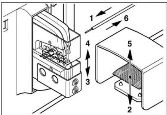
text_image Technical diagram of a device with numbered components, showing front and side views of a machine or appliance.

Phoenix Contact CF 500-230V - A Priloga - 9

text_image Technical diagram of a device with numbered components and directional arrows indicating assembly or movement.

Phoenix Contact CF 500-230V - A Priloga - 10

text_image Technical diagram of two electronic devices with labeled parts, showing internal components and mounting points.
text_image Technical diagram of a device with numbered components, showing front and side views of a box-like device.

Phoenix Contact CF 500-230V - A Priloga - 11

text_image Technical diagram showing mechanical assembly with numbered components and directional arrows indicating assembly steps
text_image Technical diagram showing labeled mechanical components with numbered parts and directional arrows indicating assembly or assembly.
natural_image Technical line drawing of two open industrial equipment units (no text or symbols)
natural_image Line drawing of an open refrigerator with internal compartments (no text or symbols)
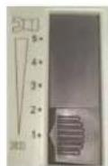
Phoenix Contact CF 500-230V - A Priloga - 12

Phoenix Contact CF 500-230V - A Priloga - 13

text_image Diagram showing installation steps of an electrical switch or fuse, labeled with components 1 through 5.
text_image Technical diagram showing exploded view of a power connector with labeled parts including socket, plug, and socket terminal.
Table of contents Click a title to access it
Manual assistant
Powered by Anthropic
Waiting for your message
Product information

Brand : Phoenix Contact

Model : CF 500-230V

Category : Electrical measuring device