USER MANUAL GLM 50-27 GC Professional BOSCH
natural_image
Illustration of a USB cable with a connector labeled (26), no text or symbols present.
4
1 609 92A 4ZJ | (14.10.2020) Bosch Power Tools
5
flowchart
graph TD
    A["Device 1"] --> B["Device 2"]
    C["Device 3"] --> D["Device 4"]
    E["Device 5"] --> F["Device 6"]
    style A fill:#f9f,stroke:#333
    style C fill:#f9f,stroke:#333
    style E fill:#f9f,stroke:#333
    style B fill:#ccf,stroke:#333
    style D fill:#ccf,stroke:#333
    style F fill:#ccf,stroke:#333
C
flowchart
graph TD
    A["Func"] --> B["Document Icon"]
    A --> C["Diagram Icon"]
    A --> D["Circle with Box"]
    A --> E["Circle with Box"]
    A --> F["Circle with Box"]
    A --> G["Circle with Box"]
    A --> H["Circle with Box"]
    A --> I["Circle with Box"]
    A --> J["Circle with Box"]
    A --> K["Circle with Box"]
    A --> L["Circle with Box"]
    A --> M["Circle with Box"]
    A --> N["Circle with Box"]
    A --> O["Circle with Box"]
    A --> P["Circle with Box"]
    A --> Q["Circle with Box"]
    A --> R["Circle with Box"]
    A --> S["Circle with Box"]
    A --> T["Circle with Box"]
    A --> U["Circle with Box"]
    A --> V["Circle with Box"]
    A --> W["Circle with Box"]
    A --> X["Circle with Box"]
    A --> Y["Circle with Box"]
    A --> Z["Circle with Box"]
    A --> AA["Circle with Box"]
    A --> AB["Circle with Box"]
    A --> AC["Circle with Box"]
    A --> AD["Circle with Box"]
    A --> AE["Circle with Box"]
    A --> AF["Circle with Box"]
    A --> AG["Circle with Box"]
    A --> AH["Circle with Box"]
    A --> AI["Circle with Box"]
    A --> AJ["Circle with Box"]
    A --> AK["Circle with Box"]
    A --> AL["Circle with Box"]
    A --> AM["Circle with Box"]
    A --> AN["Circle with Box"]
    A --> AO["Circle with Box"]
    A --> AP["Circle with Box"]
    A --> AQ["Circle with Box"]
    A --> AR["Circle with Box"]
    A --> AS["Circle with Box"]
    A --> AT["Circle with Box"]
    A --> AU["Circle with Box"]
    A --> AV["Circle with Box"]
    A --> AW["Circle with Box"]
    A --> AX["Circle with Box"]
    A --> AY["Circle with Box"]
flowchart
graph TD
    A["PRO"] --> B["i"]
    B --> C["Message Icon"]
    B --> D["Data Icon"]
    B --> E["User Interface Icon"]
    B --> F["Signal Icon"]
6
D
flowchart
graph TD
    A["① Input"] --> B["② Processing"]
    B --> C["③ Output"]
    style A fill:#f9f,stroke:#333
    style C fill:#bbf,stroke:#333
1 609 92A 4ZJ | (14.10.2020) Bosch Power Tools

Bosch Power Tools 1 609 92A 4ZJ | (14.10.2020)
8
1 609 92A 4ZJ | (14.10.2020)
Bosch Power Tools

10
M
natural_image
Simple line drawing of a device on a flat surface with a dot and horizontal line above it, and a warning symbol below (no text or labels)

natural_image
Close-up of a handheld electronic device with a black arrow pointing to its screen (no visible text or symbols)
180^
natural_image
Simple line drawing of a mobile phone on a surface with a checkmark below (no text or symbols)
90°
natural_image
Diagram showing a device with a curved arrow indicating rotation or cycle, no text or symbols present.
180^
Bosch Power Tools 1 609 92A 4ZJ | (14.10.2020)
0
2 607 001 391
1 608 M00 05J (GLM 50-27 CG)
1 608 M00 05B (GLM 50-27 C)
BT 150
0 601 096 B00
Deutsch
Sicherheitshinweise

www.bosch-pt.com/serviceaddresses
Transport
All instructions must be read and observed in order for the measuring tool to function safely. The safeguards integrated into the measuring tool may be compromised if the measuring tool is not used in accordance with these instructions. Never make warning
Bosch Power Tools 1 609 92A 4ZJ | (14.10.2020)
34 | English
signs on the measuring tool unrecognisable. SAVE THESE INSTRUCTIONS FOR FUTURE REFERENCE AND INCLUDE THEM WITH THE MEASURING TOOL WHEN TRANSFERRING IT TO A THIRD PARTY.
▶ Warning! If operating or adjustment devices other than those specified here are used or other procedures are carried out, this can lead to dangerous exposure to radiation.
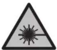
The measuring tool is delivered with a laser warning sign (marked in the illustration of the measuring tool on the graphics page).
If the text of the laser warning label is not in your national language, stick the provided warning label in your national language over it before operating for the first time.
Do not direct the laser beam at persons or animals and do not stare into the direct or reflected laser beam yourself. You could blind somebody, cause accidents or damage your eyes.
▶ If laser radiation hits your eye, you must close your eyes and immediately turn your head away from the beam.
▶ Do not make any modifications to the laser equipment.
▶ Do not use the laser goggles (accessory) as protective goggles. The laser goggles make the laser beam easier to see; they do not protect you against laser radiation.
▶ Do not use the laser goggles (accessory) as sunglasses or while driving. The laser goggles do not provide full UV protection and impair your ability to see colours.
▶ Have the measuring tool serviced only by a qualified specialist using only original replacement parts. This will ensure that the safety of the measuring tool is maintained.
▶ Do not let children use the laser measuring tool unsupervised. They could unintentionally blind themselves or other persons.
▶ Do not use the measuring tool in explosive atmospheres which contain flammable liquids, gases or dust. Sparks may be produced inside the measuring tool, which can ignite dust or fumes.
▶ Do not open the battery. There is a risk of short-circuiting.
In case of damage and improper use of the battery, vapours may be emitted. The battery can set alight or explode. Ensure the area is well ventilated and seek medical attention should you experience any adverse effects. The vapours may irritate the respiratory system.
If used incorrectly or if the battery is damaged, flammable liquid may be ejected from the battery. Contact with this liquid should be avoided. If contact accidentally occurs, rinse off with water. If the liquid comes into contact with your eyes, seek additional medical attention. Liquid ejected from the battery may cause irritation or burns.
The battery can be damaged by pointed objects such as nails or screwdrivers or by force applied externally. An internal short circuit may occur, causing the battery to burn, smoke, explode or overheat.
When the battery is not in use, keep it away from paper clips, coins, keys, nails, screws or other small metal objects that could make a connection from one terminal to another. A short circuit between the battery terminals may cause burns or a fire.
▶ Only use the battery with products from the manufacturer. This is the only way in which you can protect the battery against dangerous overload.
▶ Only charge the batteries using chargers recommended by the manufacturer. A charger that is suitable for one type of battery may pose a fire risk when used with a different battery.


Protect the battery against heat, e.g. against continuous intense sunlight, fire, dirt, water and moisture. There is a risk of explosion and short-circuiting.
▶ Caution! Using the measuring tool with Bluetooth® can cause faults to occur in other devices and systems, aeroplanes and medical devices (e.g. pacemakers, hearing aids). Also, damage to people and animals in the immediate vicinity cannot be completely excluded. Do not use the measuring tool with Bluetooth® in the vicinity of medical devices, petrol stations, chemical plants, areas with a potentially explosive atmosphere and in blasting areas. Do not use the measuring tool with Bluetooth® on aeroplanes. Avoid using the product near your body for extended periods.
The Bluetooth® word mark and logos are registered trademarks owned by Bluetooth SIG, Inc. and any use of such marks by Robert Bosch Power Tools GmbH is under license.
Product Description and Specifications
Please unfold the fold-out page with the diagram of the measuring tool and leave it open while reading the instruction manual.
36 | English
Intended Use
The measuring tool is intended for measuring distances, lengths, heights, clearances and inclines, and for calculating areas and volumes.
The measuring tool is suitable for indoor and outdoor use.
The measuring results can be transferred to other devices via Bluetooth®.
Product features
The numbering of the product features shown refers to the illustration of the measuring tool on the graphic page.
(1) Bluetooth® button
(2) Function button [Func]
(3) Minus/left [-] button
(4) Display
(5) Measuring button [▲]
(6) Plus/right [+] button
(7) Basic settings [button
(8) On/off/back button [ ]
(9) Eyelet for carrying strap ^A)
(10) Laser warning label
(11) Serial number
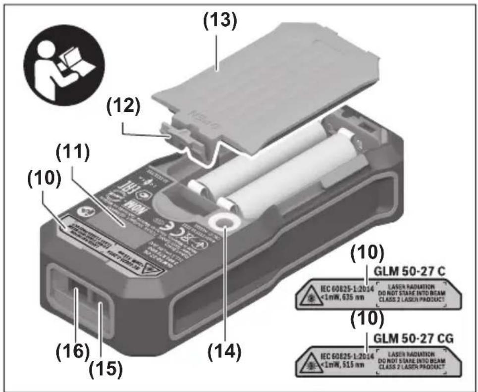
(12) Battery compartment cover locking mechanism
(13) Battery compartment cover
(14) 1/4" tripod thread
(15) Reception lens
(16) Laser beam output
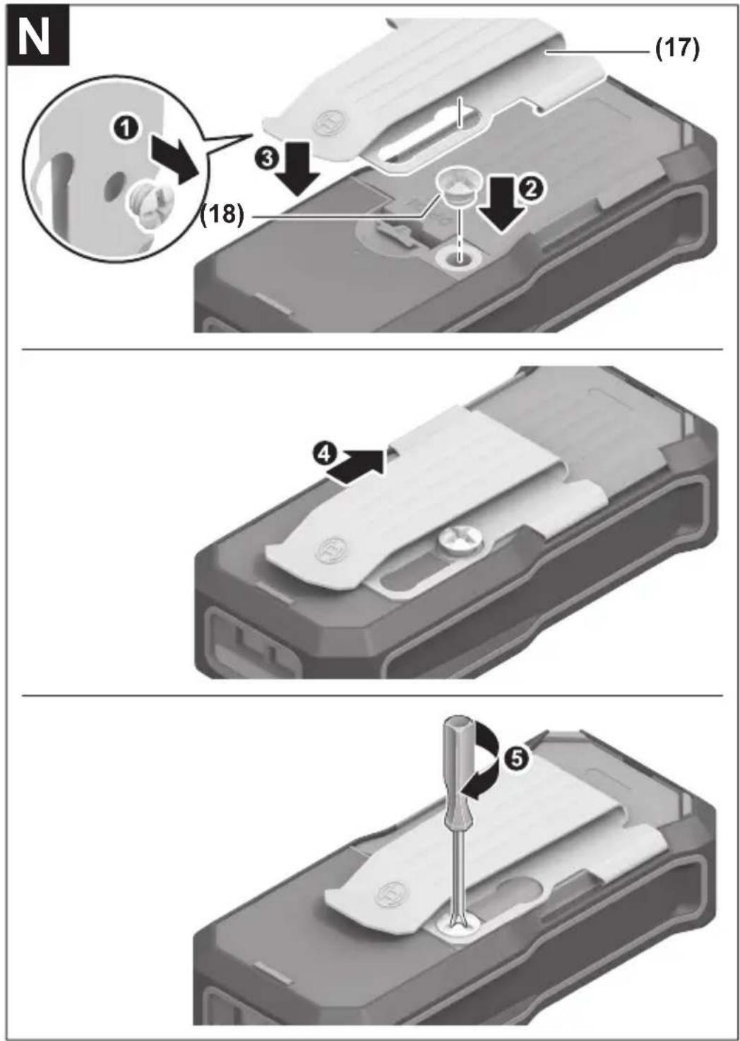
(17) Belt clip ^A)
(18) Screw ^A) for belt clip ^A)
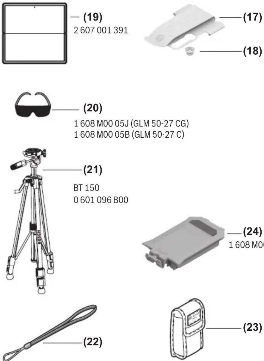
(19) Laser target plate ^A)
(20) Laser viewing glasses ^A)
(21) Tripod ^A)
(22) Carrying strap ^A)
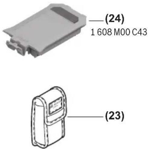
(23) Protective bag
(24) Li-ion battery pack ^A)
(25) Li-ion battery pack locking mechanism ^A)
(26) USB Type-C ^® cable ^A)B)
(27) Flap for USB Type-C® port ^A)
A) Accessories shown or described are not included with the product as standard. You can find the complete selection of accessories in our accessories range.
B) USB Type-C® and USB-C® are trademarks of USB Implementers Forum.
Display elements (selection)
(a) Reference level of measurement
(b) Connection status

Bluetooth ^® activated, connection not established

Bluetooth ^® activated, connection established
(c) Battery indicator
Digital laser measure GLM 50-27 CG GLM 50-27 C
| Article number | 3 601 K72 U.. 3 601 K72 T.. |
| Distance measurement |
| Measuring range 0.05–50 m | A) | 0.05–50 mA) |
| Measuring range (unfavourable conditions) | 0.05–20 mB) | 0.05–20 mB) |
| Measuring accuracy ±1.5 mm | A) | ±1.5 mmA) |
38 | English
Digital laser measure GLM 50-27 CG GLM 50-27 C
| Measuring accuracy (unfavour-able conditions) | ±3.0 mm^B) | ±3.0 mm^B) |
| Smallest display unit 0.5 mm 0.5 mm | | |
Indirect distance measurement and level
| Measuring range 0°–360° (4 x 90°) 0°–360° (4 x 90°) |
Grade measurement
| Measuring range 0°-360° (4 x 90°) 0°-360° (4 x 90°) |
| Measuring accuracy (typical) ±0.2° | C)D) | ±0.2°C)D) |
| Smallest display unit 0.1° 0.1° | | |
General
| Operating temperature -10 °C to +45 °C | E) | -10 °C to +45 °CE) |
| Permitted charging temperature range | 0 °C to +60 °C | 0 °C to +60 °C |
| Storage temperature -20°C to +70°C -20°C to +70°C |
| Relative air humidity max. 90 % 90 % |
| Max. altitude 2000 m 2000 m |
| Pollution degree according to IEC 61010-1 | 2^F) | 2^F) |
| Laser type | 515 nm, < 1 mW | 635 nm, < 1 mW |
| Divergence of the laser beam | < 1.5 mrad (full angle) | < 1.5 mrad (full angle) |
Automatic switch-off after approx.
| - Laser | 20 s | 20 s |
| - Measuring tool (without measurement) | 5 minG) | 5 minG) |
| Weight according to EPTA-Procedure 01:2014 | 0.17 kg 0.17 kg |
| Dimensions | 119 x 53 x 29 mm | 119 x 53 x 29 mm |
| Protection rating | IP 65 (protection against dust ingress and water jets) | IP 65 (protection against dust ingress and water jets) |
English | 39
Digital laser measure GLM 50-27 CG GLM 50-27 C
| Batteries 2 x 1.5 V LR6 (AA) 2 x 1.5 V LR6 (AA) |
| Unit of measurement setting m, ft, in m, ft, in |
| Battery pack (accessory) Li-ion Li-ion |
| Type BA 3.7 V 1.0 Ah A BA 3.7 V 1.0 Ah A |
| Article number | 1 607 A35 0N8 1 607 A35 0N8 |
| USB charging connection Type-C® Type-C® |
| recommended USB Type-C® cable | 1 600 A01 6A8 1 600 A01 6A8 |
| Rated voltage 3.7 V 3.7 V | - | - |
| Capacity 1.0 Ah | 1.0 Ah | |
| Number of battery cells | 1 | 1 |
| Power supply |
| Output voltage | 5.0 V 5.0 V | - |
| Output current | 500 mA | 500 mA |
| Recommended power supply | 2 609 120 713 (EU)2 609 120 718 (UK)1 600 A01 3A0 (ARG)1 600 A01 3A1 (MEX)1 600 A01 3A2 (BRL) | 2 609 120 713 (EU)2 609 120 718 (UK)1 600 A01 3A0 (ARG)1 600 A01 3A1 (MEX)1 600 A01 3A2 (BRL) |
| Data transfer |
| Bluetooth® | Bluetooth®(4.2 Low Energy) ^H) | Bluetooth®(4.2 Low Energy) ^H) |
| Operating frequency band | 2402-2480 MHz | 2402-2480 MHz |
40 | English
Digital laser measure GLM 50-27 CG GLM 50-27 C
Max. transmission power 8 mW 8 mW
A) For measurements from the front edge of the measuring tool, this applies for high reflectivity of the target (e.g. a white-painted wall), weak backlighting and 25 °C operating temperature. In addition, a deviation of ±0.05 mm/m must be taken into account, depending on the distance.
B) For measurements from the front edge of the measuring tool, this applies for high reflectivity of the target (e.g. a white-painted wall), strong backlighting and 25 °C operating temperature. In addition, a deviation of ±0.15 mm/m must be taken into account, depending on the distance.
C) After user calibration at 0^ and 90^ ; An additional grade error of ±0.01^/degree to 45^ (max.) has to be taken into account. The left-hand side of the measuring tool serves as the reference level for grade measurement.
D) At an operating temperature of 25 °C
E) In continuous measurement mode, the max. operating temperature is +40 °C.
F) Only non-conductive deposits occur, whereby occasional temporary conductivity caused by condensation is expected.
G) Bluetooth® deactivated
H) When using Bluetooth® Low Energy devices, it may not be possible to establish a connection depending on the model and operating system. Bluetooth® tools must support the GATT profile.
The serial number (11) on the type plate is used to clearly identify your measuring tool.
Bluetooth® interface
Transmitting data to other devices
The measuring tool is fitted with a Bluetooth® module which enables wireless data transfer to certain mobile devices with a Bluetooth® interface (e.g. smartphone, tablet).
Information about the system requirements for a Bluetooth® connection can be found on the Bosch website at www.bosch-pt.com
▶ Further information can be found on the Bosch product page.
When transmitting data by means of Bluetooth ^® , time lags may occur between the mobile device and the measuring tool. This can be due to the distance between the two devices or the measurement object itself.
Activating the Bluetooth® interface for transmitting data to a mobile device
Ensure that the Bluetooth® interface is activated on your mobile device.
Press the (1) button to bring up the Bluetooth® menu and press the (1) button again (or the (6) [+] button), to activate the Bluetooth® interface. If multiple active measuring tools are found, select the appropriate measuring tool using the serial number. You can find the serial number (11) on your measuring tool's type plate. The connection status and the active connection (b) are displayed in the status bar (h) of the measuring tool.
Bosch applications are available to expand the range of functions. Depending on the device, you can download these applications from the corresponding app stores.
Deactivating the Bluetooth® interface
Press the (1) button to bring up the Bluetooth® menu and press the (1) button again (or the (3) [-] button), to deactivate the Bluetooth® interface.
Assembly
Inserting/changing the batteries
Using alkali-manganese or nickel metal hydride rechargeable batteries (especially at low operating temperatures) is recommended for operation of the measuring tool.
With 1.2 V batteries, more measurements may be possible than with 1.5 V batteries, depending on the capacity.
Press the locking mechanism (12) to open the battery compartment cover (13) and remove the battery compartment cover. Insert the batteries. When inserting, pay attention to the correct polarity according to the representation on the inside of the battery compartment.
When the state of charge of the batteries or reusable batteries is low, a request to activate the battery saver mode will appear on the display. When the battery saver mode is activated, the battery runtime will be extended and the battery symbol on the display will have a yellow outline(see ""Settings" menu (see figure C)", page 44).
When the empty battery symbol first appears on the display, only a limited number of measurements is still possible. When the battery symbol is empty and flashes red, no further measurements are possible. Replace the batteries or reusable batteries.
Always replace all the batteries at the same time. Only use batteries from the same manufacturer and which have the same capacity.
▶ Take the batteries out of the measuring tool when you are not using it for a prolonged period of time. The batteries can corrode and self-discharge during prolonged storage.
Inserting/changing the lithium-ion battery pack (accessory)
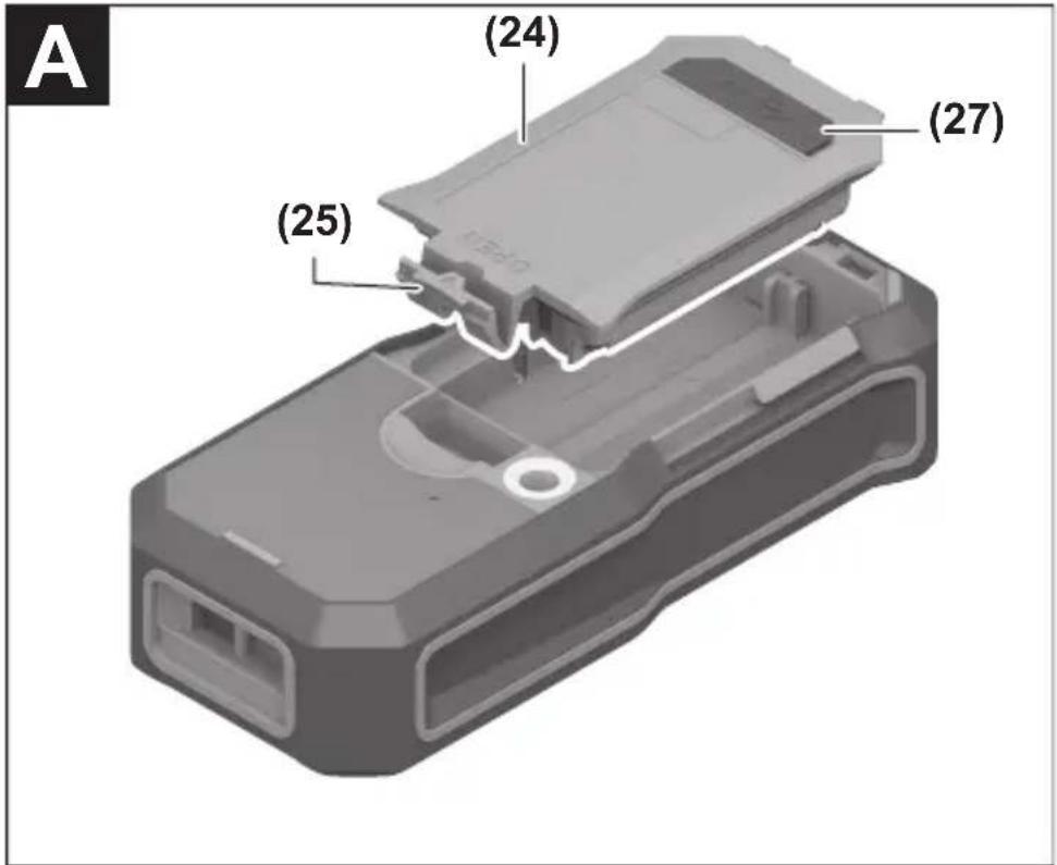
Insert the lithium-ion battery pack (24) (see figure A).
To remove the lithium-ion battery pack (24), press the locking mechanism (25) and take the lithium-ion battery pack out.
42 | English
Operation
Charging the lithium-ion battery pack (accessory)
Note: The battery is supplied partially charged. To ensure full capacity of the battery, completely charge the battery before the first use.
The USB port for connecting the USB cable (26) and the charging indicator light can be found under the flap for the USB port (27) on the lithium-ion battery pack (24) (accessory). Open the flap for the USB port (27) and connect the USB cable (26).
During the charging process, the battery indicator on the display may differ from the actual state of charge of the lithium-ion battery pack (24). When the lithium-ion battery pack (24) is fully charged, the charging indicator light will light up green.
During charging, the charging indicator light lights up yellow. A red charging indicator light indicates that the charging voltage or charging current are unsuitable.
Start-Up
▶ Never leave the measuring tool unattended when switched on, and ensure the measuring tool is switched off after use. Others may be dazzled by the laser beam.
▶ Protect the measuring tool from moisture and direct sunlight.
Do not expose the measuring tool to any extreme temperatures or variations in temperature. For example, do not leave it in a car for extended periods of time. In case of large variations in temperature, allow the measuring tool to adjust to the ambient temperature before putting it into operation. The precision of the measuring tool may be compromised if exposed to extreme temperatures or variations in temperature.
▶ Avoid substantial knocks to the measuring tool and avoid dropping it. Always carry out an accuracy check before continuing work if the measuring tool has been subjected to severe external influences (see "Checking accuracy and calibrating the grade measurement (see figure M)", page 51) and (see "checking accuracy of the distance measurement", page 51).
The measuring tool is equipped with a wireless interface. Local operating restrictions, e.g. in aeroplanes or hospitals, must be observed.
Switching on/off
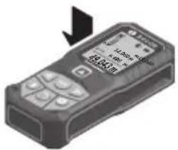
- To switch on the measuring tool and the laser, briefly press the measuring button (5) [▲].
- To switch on the measuring tool without the laser, briefly press the on/off/back button (8) [ ]
▶ Do not direct the laser beam at persons or animals and do not stare into the laser beam yourself (even from a distance).
When switching on the measuring tool for the first time, you will be prompted to set your preferred language for the display text.
To switch off the measuring tool, press and hold the on/off/back button (8) [ ]
The measured values and device settings in the memory are retained when you switch off the measuring tool.
Measuring process
When switching on for the first time, the measuring tool will be in the length measurement function. When switching on every subsequent time, the measuring tool will be in the measuring function that was last used. For a different measuring function, press the (2) [Func] button. Use the (6) [+] button or the (3) [-] button to select the required measuring function (see "Measuring Functions", page 44). Activate the measuring function with the (2) [Func] button or with the measuring button (5) [▲].
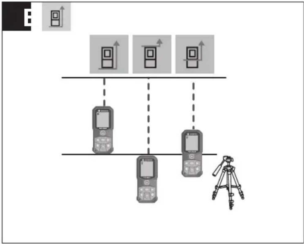
There are three settings available for the reference level for measurement (see "Selecting the reference level (see figure B)", page 43).
Apply the measuring tool to the point at which you want to start the measurement (e.g. wall).
Note: If the measuring tool has been switched on using the on/off/back button (8) [ ] briefly press the measuring button (5) [ ] to switch the laser on.
To initiate the measurement, briefly press the measuring button (5) [▲] The laser beam will then switch off. For a further measurement, repeat this process.
▶ Do not direct the laser beam at persons or animals and do not stare into the laser beam yourself (even from a distance).
Note: The measured value typically appears within half a second, and no later than approximately four seconds. The duration of the measurement depends on the distance, the lighting conditions and the reflective properties of the target surface. Upon completion of the measurement, the laser beam will automatically switch off.
You can choose between three different reference levels for the measurement:
- The rear edge of the measuring tool (e.g. when placing against walls)
- The front edge of the measuring tool (e.g. when measuring from a table edge)
- The centre of the thread (14) (e.g. for tripod measurements)
To select the reference level, press the (7) [button]. Then select the "Reference level" setting with the measuring button (5) [▲] or the (2) [Func] button. Then use the (6) [+]
44 | English
button or the (3) [-] button to select the required reference level. Every time the measuring tool is switched on, the last selected reference level is preset.
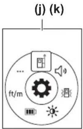
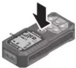
Press the (7) [button to access the "Settings" menu (j).
Use the (6) [+] button or the (3) [-] button to select the required setting and confirm this by pressing the measuring button (5) [▲] or the (2) [Func] button.
Use the (6) [+] button or the (3) [-] button to select the required setting and confirm this by pressing the measuring button (5) [▲] or the (2) [Func] button.
To exit the "Settings" menu, press the on/off/back button (8) [ ]
The following settings are available:
- Switching sound on/off
- Switching vibration on/off : Two short vibrations indicate a successful measurement; one long vibration indicates a measurement error.

- Display illumination

- Battery saver mode: When battery saver mode is switched on, sound and vibration are deactivated and the display brightness is reduced. This extends the battery runtime.
- Changing the unit of measurement ft/m
- Setting the language

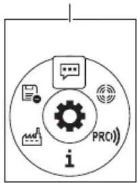
- PRO360: Initial activation is required. Data can only be transferred using a suitable app or computer program. After changing the battery, the measuring tool must be switched on once to restart PRO360. PRO360 can be deactivated again at any time. You can find additional information about PRO360 at www.pro360.com.
- Device information i
- Factory Reset
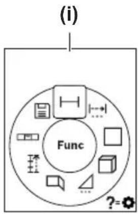
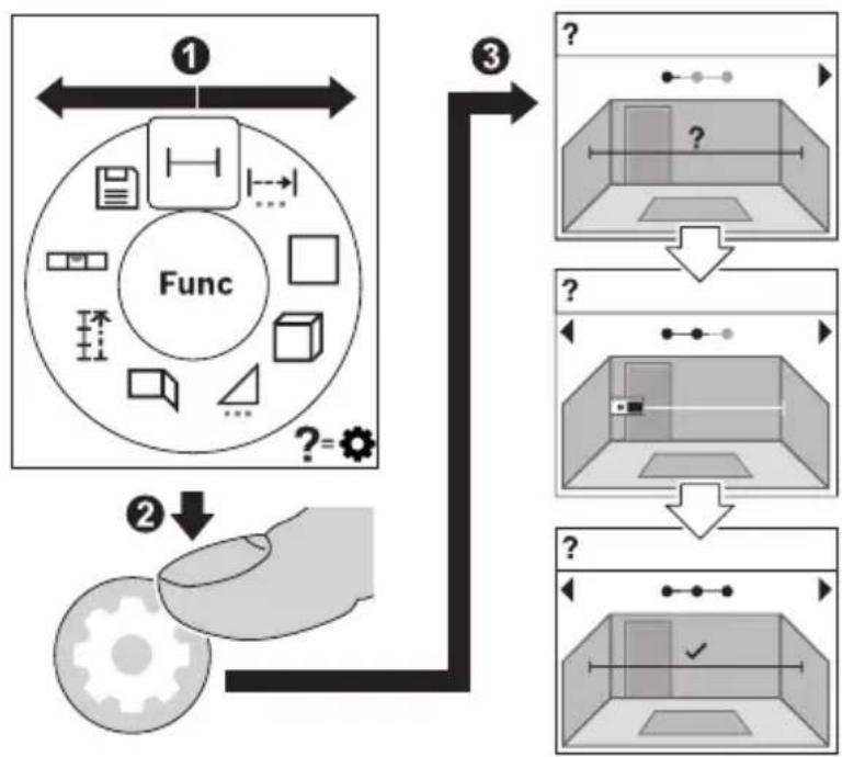
Measuring functions
To select a measuring function, press the button (2) [Func]. Select the desired measuring function with the button (6) [+] or the button (3) [-].
To start the help function, press the (7) [button]. The help function shows the detailed procedure for the selected measuring function.
Measuring length
Select the length measurement mode
1 609 92A 4ZJ | (14.10.2020) Bosch Power Tools
To switch on the laser beam, briefly press the measuring button (5) [▲]
To measure, briefly press the measuring button (5) [▲] The measured value will be shown at the bottom of the display.
Repeat the above steps for each subsequent measurement. The last measured value is at the bottom of the display, the penultimate measured value is above it, and so on.
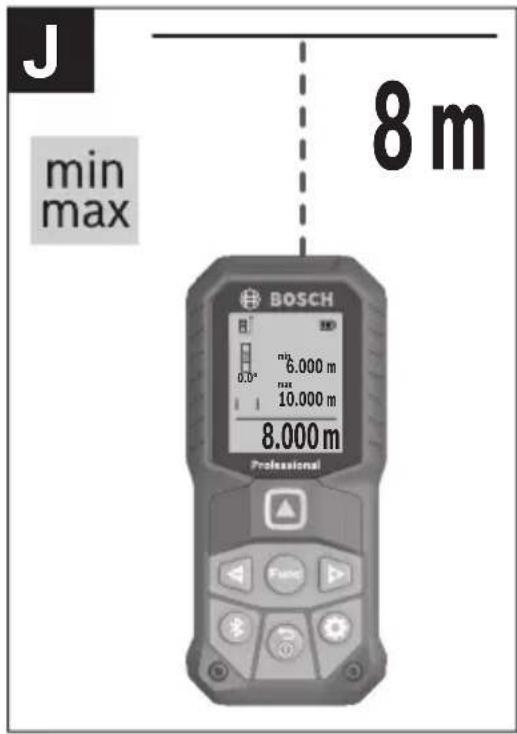
Continuous measurement
In continuous measurement mode, the measuring tool can be moved relative to the target, during which the measured value will be updated approx. every half a second. You can, for example, move a desired distance away from a wall while reading off the current distance at all times.
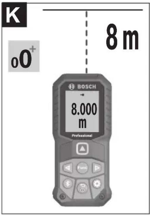
Select continuous measurement 1. Select one of the following functions:
- Min/max: The smallest and largest measured value are permanently shown on the display (see figure J).
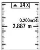
– Large numbers: The measured value is displayed in an enlarged format for better legibility (see figure K).
- Tape measure: The distance will be displayed visually, as with a tape measure (see figure L). Note: The distance from the marking is shown in the display in the tape measure function. The reference is not the edge of the measuring tool.
To switch on the laser beam, briefly press the measuring button (5) [▲]
Move the measuring tool until the required distance is shown at the bottom of the display.

Briefly pressing the measuring button (5) [▲] will interrupt the continuous measurement. The current measured value will be shown at the bottom of the display. Pressing the measuring button (5) [▲] once more will start the continuous measurement again.
Continuous measurement automatically switches off after four minutes.
Area measurement
Select the area measurement mode □
46 | English
Then measure the width and length one after the other as with a length measurement. The laser beam remains switched on between the two measurements. The distance to be measured flashes in the indicator for area measurement □
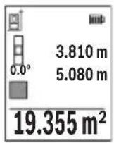
The first measured value is shown at the top of the display.
After the second measurement has been completed, the area will be automatically calculated and displayed. The end result is shown at the bottom of the display, while the individual measured values are shown above it.
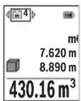
Volume measurement
Select the volume measurement mode.
Then measure the width, length and depth one after the other as with a length measurement. The laser beam remains switched on between the three measurements. The distance to be measured flashes in the indicator for volume measurement ☐
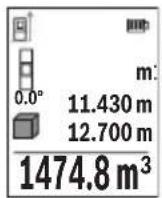
The first measured value is shown at the top of the display.
After the third measurement has been completed, the volume will be automatically calculated and displayed. The end result is shown at the bottom of the display, while the individual measured values are shown above it.
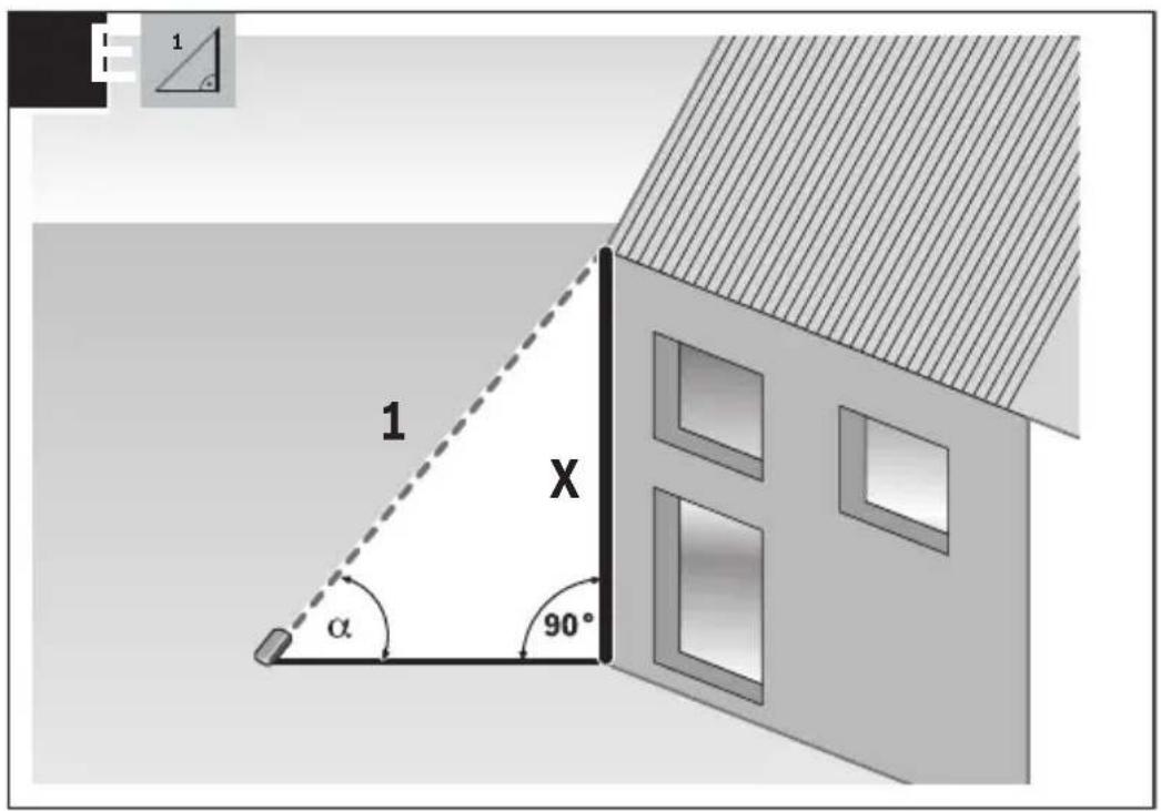
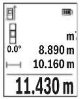
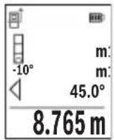
Indirect distance measurement
For indirect length measurements, three measuring modes are available. Each measuring function can be used for determining different distances.
The indirect distance measurement is used to determine distances that cannot be measured directly, due to an obstacle that would impede the path beam or the absence of a target surface that could serve as a reflector. This measuring procedure can only be employed vertically. Any horizontal deviation will lead to measurement errors.
Note: Indirect distance measurement is always less accurate than direct distance measurement. For application-related reasons, measuring errors can be greater than with direct distance measurement. To improve the accuracy of measurement, we recommend the use of a tripod (accessory).
The laser beam remains switched on between the individual measurements.
Select the indirect height measurement mode
Ensure that the measuring tool is at the same height as the lower measuring point. Then tilt the measuring tool around the reference level and measure distance 1 as for a length measurement (displayed as a red line).
Once the measurement is complete, the result for the required distance X is displayed in the result line (e). The measured values for distance 1 and angle can be found in the measured value rows (d).
The measuring tool can indirectly measure all distances that lie in the vertical level of the measuring tool.
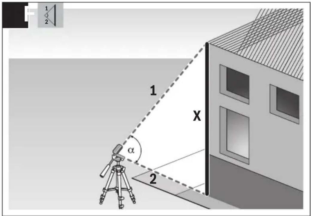
Select the double indirect height measurement mode.
Measure distances 1 and 2 in succession as for a length measurement.
Once the measurement is complete, the result for the required distance X is displayed in the result row (e). The measured values for distances 1 and 2 and angle a can be found in the measured value rows (d).
Ensure that the reference level for the measurement (e.g. the rear edge of the measuring tool) remains in exactly the same place for all
the individual measurements in a single measuring process.
Select the indirect length measurement mode
Ensure that the measuring tool is at the same height as the required measuring point.
Then tilt the measuring tool around the reference level and measure distance 1 as for a length measurement.
Once the measurement is complete, the result for the required distance X is displayed in the result row (e). The measured values for distance 1 and angle a can be found in the measured value row (d).
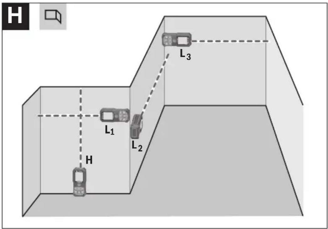
The wall area measurement is used to determine the sum of multiple individual areas with a common height. In the illustrated example, the total area of several walls that have the same ceiling height H but different lengths L is to be determined.
Select the wall area measurement mode.
48 | English
Measure the ceiling height H as for a length measurement. The measured value is displayed in the top measured-value line. The laser remains switched on.
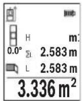
Then measure the length L_1 of the first wall. The area is automatically calculated and displayed in the result line (e). The last measured value for length can be found in the bottom measured value line (d). The laser remains switched on.
Now measure the length L_2 of the second wall. The individual measured value displayed in the measured value line (d) is added to the
length L_1 . The sum of the two lengths (displayed in the middle measured value line (d)) is multiplied by the saved height H. The total area value is displayed in the result line (e).
You can measure any number of lengths L_x , which will be automatically added and multiplied by the height H. The requirement for a correct area calculation is that the first measured length (for example the ceiling height H) is identical for all sub-areas.
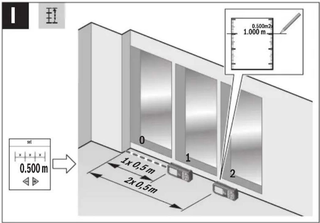
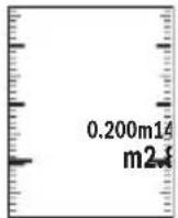
The stake out function repeatedly measures a defined length (distance). These lengths can be transferred to a surface, for example to enable material to be cut into pieces of equal lengths or to install stud walls in a drywall construction. The minimum adjustable length is 0.1 m and the maximum length is 50 m.
Note: The distance from the marking is shown in the display in the stake out function. The reference is not the edge of the measuring tool.
Select the stake out function
Use the button (6) [+] or the button (3) [-] to set the required length.
Begin the stake out function by pressing the measuring button (5) [▲] and slowly move away from the starting point.
The measuring tool continuously measures the distance to the starting point. The defined length and the current measured value are thereby displayed. The lower or upper arrow displays the shortest distance to the next or last marking.
The left factor specifies how many times the defined length has already been reached. A green measured value indicates that a length has been reached for marking purposes.
A blue measured value indicates the actual value when the reference value is outside the display.
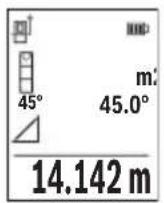
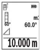
Grade measurement/digital spirit level
Select the inclination measurement/digital spirit level
The measuring tool automatically switches between two states.
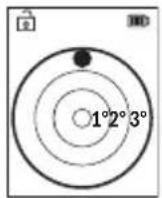
The digital spirit level is used to check the horizontal or vertical alignment of an object (e.g. washing machine, refrigerator, etc.).
When the inclination exceeds 3^ , the ball in the display lights up red.
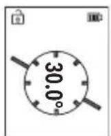
Grade measurement is used to measure a slope or incline (e.g. of stairs, railings, when fitting furniture, laying pipes, etc.).
The left-hand side of the measuring tool serves as the reference level for grade measurement.
Memory value display
The value or end result of each completed measurement is automatically saved.
Maximum 30 values (measured values or end results) can be retrieved.
Select the memory function [ ]
The number of the memory value is shown at the top of the display, the corresponding memory value is shown at the bottom and the corresponding measuring function is shown on the left.
Press the [+] button (6) to browse forwards through the saved values.
Press the [-] button (3) to browse backwards through the saved val-
ues.
The oldest value is located in position 1 in the memory, while the newest value is in position 30 (when 30 memory values are available). If a further value is saved, the oldest value in the memory is always deleted.
Deleting the memory
To delete an individual memory value, select this value(see "Memory value display", page 49). To delete, first press the on/off/back button (8) [ ] and confirm this by pressing the (2) [Func] button.
To delete all the contents of the memory, press the (7) [button and select the function. Then press the (6) [+] button and confirm this by pressing the (2) [Func] button.
50 | English
Adding/subtracting values
Measured values or end results can be added or subtracted.
Adding values
The following example describes the addition of areas:
Measure an area as described in the "Area measurement" section Area measurement.

Press the [+] button (6). The calculated area and the + symbol will be displayed.
Press the measuring button (5) [▲] to start another area measurement. Measure the area as described in the "Area measurement" section Area measurement. Once the second measurement is completed, the result of the second area measurement is displayed be-
low. To show the end result, press the measuring button (5) [▲] once more.
Note: In the case of a length measurement, the end result is displayed immediately.
To exit addition, press the [Func] button (2).
Subtracting values
To subtract values, press the button (3) [-]. The subsequent steps are the same as for the section on adding values.
Deleting measured values
Briefly pressing the on/off/back button (8) [ ] will delete the last measured value in all measuring functions. Repeatedly pressing the on/off/back button (8) [ ] briefly will delete the measured values in reverse order.
Practical advice
The measuring tool is equipped with a wireless interface. Local operating restrictions, e.g. in aeroplanes or hospitals, must be observed.
General advice
The reception lens (15) and the laser beam output (16) must not be covered during the measuring process.
The measuring tool must not be moved during a measurement (with the exception of the continuous measurement and grade measurement functions). For this reason, place the measuring tool against or on a firm surface whenever possible.
Influences on the measuring range
The measuring range depends on the lighting conditions and the reflective properties of the target surface. For better visibility of the laser beam in bright extraneous light, use
the laser viewing glasses (20) (accessory) and the laser target plate (19) (accessory) or shade the target area.
Influences on the measurement result
Due to physical effects, the possibility of inaccurate measurements when measuring various surfaces cannot be excluded. These include:
- Transparent surfaces (e.g. glass, water)
- Reflective surfaces (e.g. polished metal, glass)
– Porous surfaces (e.g. insulating materials)
- Structured surfaces (e.g. roughcast, natural stone).
If necessary, use the laser target plate (19) (accessory) on these surfaces.
Inaccurate measurements are also possible where the laser is pointed at target surfaces diagonally.
Layers of air at different temperatures and indirectly received reflections can also influence the measured value.
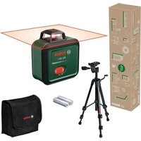
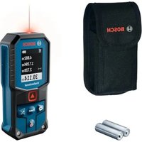
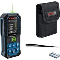
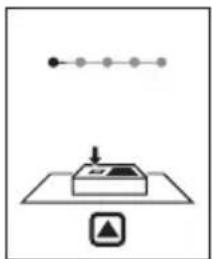
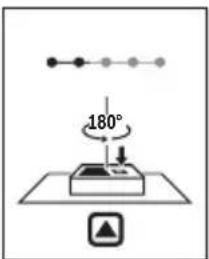
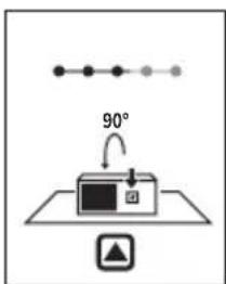
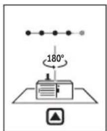
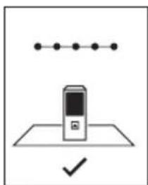
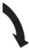
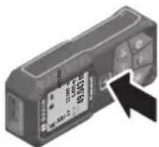
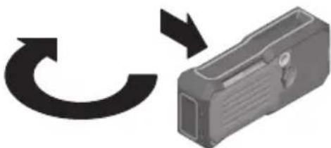
Regularly check the accuracy of the grade measurement. This is accomplished by means of a reverse measurement. To do this, lay the measuring tool on a table and measure the inclination. Turn the measuring tool by 180^ and measure the inclination again. The difference between the displayed values must not exceed 0.3^ .
In the event of larger deviations, you have to recalibrate the measuring tool. To do so, select in the settings. Follow the instructions on the display.
We recommend that you perform an accuracy check and if necessary a calibration of the measuring tool after extreme temperature variations and after impact to the tool. After a temperature variation, the measuring tool must adjust to the ambient temperature for a while before calibration is performed.
Accuracy Check of the Distance Measurement
You can check the accuracy of the measuring tool as follows:
- Choose a measuring section of approx. 3–10 m in length that is permanently unchanged, the exact length of which is known to you (e.g. room width, door opening). The measurement should be taken under favourable conditions, i.e. the measuring section should be indoors and the target surface for the measurement should be smooth and reflect well.
- Measure the section ten times in succession.
The deviation of the individual measurements from the mean value must not exceed ±4 mm over the entire measuring section in favourable conditions. Record the measurements in order to be able to compare the accuracy at a later date.
52 | English
Working with the tripod (accessory)
The use of a tripod is particularly necessary for larger distances. Place the measuring tool with the 1/4" thread (14) on the quick-release plate of the tripod (21) or of a commercially available camera tripod. Tighten it using the locking screw of the quick-release plate.
Set the reference level for measurements with a tripod in the settings (see "Selecting the reference level (see figure B)", page 43).
With the belt clip (17), the measuring tool can be conveniently secured to your belt.
Error message
If a measurement cannot be performed correctly, the "Error" message will appear in the display. Start the measurement again.

The measuring tool monitors correct functioning in every measurement. If a defect is detected, the display will indicate only the symbol shown opposite and the measuring tool switches itself off. In this case, have the measuring tool checked by an after-sales service agent for Bosch power tools.
Maintenance and Service
Maintenance and Cleaning
Store and transport the measuring tool only in the supplied protective bag (23).
Keep the measuring tool clean at all times.
Never immerse the measuring tool in water or other liquids.
Wipe off any dirt using a damp, soft cloth. Do not use any detergents or solvents.
Take particular care of the reception lens (15), which must be handled with the same level of care you would give to a pair of glasses or a camera lens.
If the measuring tool needs to be repaired, send it off in the protective bag (23).
After-Sales Service and Application Service
Our after-sales service responds to your questions concerning maintenance and repair of your product as well as spare parts. You can find explosion drawings and information on spare parts at: www.bosch-pt.com
The Bosch product use advice team will be happy to help you with any questions about our products and their accessories.
In all correspondence and spare parts orders, please always include the 10-digit article number given on the nameplate of the product.
Great Britain
Robert Bosch Ltd. (B.S.C.)
P.O. Box 98
Broadwater Park
North Orbital Road
Denham Uxbridge
UB 9 5HJ
At www.bosch-pt.co.uk you can order spare parts or arrange the collection of a product in need of servicing or repair.
Tel. Service: (0344) 7360109
E-Mail: boschservicecentre@bosch.com
You can find further service addresses at:
www.bosch-pt.com/serviceaddresses
Transport
Lithium-ion batteries are subject to the Dangerous Goods Legislation requirements. The batteries are suitable for road-transport by the user without further restrictions.
When shipping by third parties (e.g.: by air transport or forwarding agency), special requirements on packaging and labelling must be observed. For preparation of the item being shipped, consulting an expert for hazardous material is required.
Dispatch battery packs only when the housing is undamaged. Tape or mask off open contacts and pack up the battery in such a manner that it cannot move around in the packaging. Please also observe the possibility of more detailed national regulations.
Disposal
Measuring tools, rechargeable/non-rechargeable batteries, accessories and packaging should be sorted for environmental-friendly recycling.
Do not dispose of the measuring tools or rechargeable/non-rechargeable batteries with household waste.
Only for EU countries:
According to the Directive 2012/19/EU, measuring tools that are no longer usable, and according to the Directive 2006/66/EC, defective or used battery packs/batteries, must be collected separately and disposed of in an environmentally correct manner.
54 | Français
Battery packs/batteries:
Li-ion:
Please observe the notes in the section on transport (see "Transport", page 53).
Français
Robert Bosch (France) S.A.S.
www.bosch-pt.com/serviceaddresses
Transport
www.bosch-pt.com/serviceaddresses
Transporte
www.bosch-pt.com/serviceaddresses
Transporte
Capacità 1,0 Ah 1,0 Ah
www.bosch-pt.com/serviceaddresses
Trasporto
www.bosch-pt.com/serviceaddresses
Vervoer
Bosch Service Center
Telegrafvej 3
2750 Ballerup
På www.bosch-pt.dk kan der online bestilles reservedele eller oprettes en reparations ordre.
Tlf. Service Center: 44898855
Fax: 44898755
E-Mail: vaerktoej@dk.bosch.com
www.bosch-pt.com/serviceaddresses
Transport
Bosch Service Center
Telegrafvej 3
2750 Ballerup
Danmark
Tel.: (08) 7501820 (inom Sverige)
Fax: (011) 187691
www.bosch-pt.com/serviceaddresses
Transport
www.bosch-pt.com/serviceaddresses
Transport
www.bosch-pt.com/serviceaddresses
Kuljetus
www.bosch-pt.com/serviceaddresses
Μεταφορά
www.bosch-pt.com/serviceaddresses
Nakliye
Robert Bosch Sp. z o.o.
www.bosch-pt.com/serviceaddresses
Transport
Bosch Service Center PT
K Vápence 1621/16
692 01 Mikulov
www.bosch-pt.com/serviceaddresses
Přeprava
www.bosch-pt.com/serviceaddresses
Transport
www.bosch-pt.com/serviceaddresses
Szállítás
www.bosch-pt.com/serviceaddresses
Транспортировка
www.bosch-pt.com/serviceaddresses
Транспортування
www.bosch-pt.com/serviceaddresses
Тасымалдау
Service scule electrice
Strada Horia Măcelariu Nr. 30–34, sector 1
013937 Bucureşti
www.bosch-pt.com/serviceaddresses
Transport
Service scule electrice
Strada Horia Măcelariu Nr. 30–34, sector 1
013937 Bucureşti, România
www.bosch-pt.com/bg/bg/
www.bosch-pt.com/serviceaddresses
478 | Български
Транспортиране
www.bosch-pt.com/serviceaddresses
Транспорт
(6) Taster plus/desno [+]