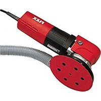
X 1107 VE - Sander Flex - Free user manual and instructions
Find the device manual for free X 1107 VE Flex in PDF.


| Product type | Sander |
| Brand | Flex |
| Model | X 1107 VE |
| Supply voltage | 230 V / 50 Hz |
| Protection class | II (double insulation) |
| Input power | 710 W |
| Output power | 420 W |
| Stroke | 8.8 mm |
| No-load speed | 4300 – 13000 min⁻¹ |
| Max. abrasive disc diameter | 150 mm |
| Extraction connection diameter | 28 mm |
| Weight (without cord) | 2.7 kg |
| Cord length | 4.0 m |
| Sound pressure level | 88 dB(A) |
| Sound power level | 99 dB(A) |
| Vibration value | 7.2 m/s² (K=1.5) |
| Abrasive attachment type | Hook and loop |
| Speed regulation | Electronic, continuous (dial 1-6) |
| Intended use | Dry sanding of wood, metal, plastic, paint, filler |
| Extraction | Integrated, 28 mm connection |
| Safety | Automatic shutdown of worn carbon brushes |
| Maintenance | Regular cleaning, replacement with original brushes |
| Approvals | CE, EN 60745 |
Frequently Asked Questions - X 1107 VE Flex
User questions about X 1107 VE Flex
0 question about this device. Answer the ones you know or ask your own.
Ask a new question about this device
Download the instructions for your Sander in PDF format for free! Find your manual X 1107 VE - Flex and take your electronic device back in hand. On this page are published all the documents necessary for the use of your device. X 1107 VE by Flex.
USER MANUAL X 1107 VE Flex
natural_image
Illustration of a power tool with meshing and a button, shown in grayscale (no text or symbols)Original operating instructions 10
natural_image
Close-up of a mechanical component with a circular base and mounting holes, showing internal structure (no text or symbols visible)natural_image
Illustration of a mechanical power tool with a threaded end and central hub (no text or symbols)natural_image
Close-up of a car air vent with a mounted sensor or sensor component, showing airflow direction (no text or symbols)natural_image
Close-up of a car air vent with a down arrow and directional arrows, no visible text or symbolsnatural_image
Illustration of hands using a power tool on a textured surface (no text or symbols visible)Manager Research & Development (R & D)
Klaus Peter WeinperEckhard F Head of Quality Department (QD)
29.06.2015
Symbols used in this manual ..... 10
Technical specifications ..... 10
For your safety 11
Noise and vibration 12
Overview 13
Operating instructions 14
Maintenance and care 15
Disposal information ..... 16
C€-Declaration of Conformity .....16
Exemption from liability ..... 16
Symbols used in this manual

WARNING!
Denotes impending danger.
Non-observance of this warning may result indeath or extremely severe injuries.

CAUTION!
Denotes a possibly dangerous situation.
Non-observance of this warning may result
inslight injury or damage to property.

NOTE
Denotes application tips and important information.
Symbols on the power tool

Before switching on the power tool, read the operating manual!

Wear goggles!

Disposal information for the old machine (see page 16)!
Technical specifications
| Machine type ander X 1107 VE | ||
| Voltage V/Hz 230/50 | ||
| Protection class | II/☐ | |
| Power input W 710 | ||
| Power output W 420 | ||
| Stroke mm 8.8 | ||
| No load stroke rate | min^{-1}$ | 4,300–13,000 |
| Max. grinding tool diameter | mm | 150 |
| Connection-∅ of dust extractor | mm | 28 |
| Weight (without power cord) | kg | 2.7 |
For your safety

WARNING!
Before using the power tool, please read and follow:
–these operating instructions,
-the "General safety instructions" on the handling of power tools in the enclosed booklet (leaflet-no.: 315.915),
–the currently valid site rules and the regulations for the prevention of accidents.
This power tool is state of the art and has been constructed in accordance with the acknowledged safety regulations.
Nevertheless, when in use, the power tool maybe a danger to life and limb of the user or a third party, or the power tool or other property may be damaged.
The power tool may be operated only if it is - a s i n t e n d e d ,
-in perfect working order.
Faults which impair safety must be repaired immediately.
Intended use
This sander is designed
– for commercial use in industry and trade,
– for coarse and fine sanding of wood, metal, plastic, paint, filler and similar materials,
– for use with Velcro sandpaper and accessories which are indicated in these instructions or which are recommended by the manufacturer.
Safety instructions for sander

WARNING!
Read all safety instructions and other instructions. Failure to observe the safety instructions and other instructions may result in an electric shock, fire and/or serious injuries. Keep all safety instructions and other instructions in a safe place for the future.
■ Attention Risk of fire! Avoid overheating the material to be ground and the grinder. Always empty the dust container before taking breaks from work.
Grinding dust in the dust sack, microfilter, paper sack (or in the filter sack or filter
of the dust extractor) may self-ignite under unfavourable conditions, e.g. caused by flying sparks when grinding metals. It is particularly hazardous if the grinding dust is mixed with paint or polyurethane residue or other chemical substances and if the material is ground for a long time until hot.
■ Ensure that nobody can be endangered by flying sparks. Remove nearby flammable materials. When metal is being ground, flying sparks occur.
■ Dust released from materials, such as lead paints, some types of wood, minerals and metal, may be hazardous to the operator or people in the vicinity. Inhaling or touching these dusts may result in respiratory diseases and/or allergic reactions.
- Ensure the work place is well ventilated!
- If possible, use external dust extraction.
- It is recommended to wear a respirator mask belonging to filter class P2.
■ Use the electric power tool for dry sanding only. If water penetrates the electric power tool, there is an increased risk of electric shock.
■ When working, hold the electric power tool firmly with both hands and ensure that you have a secure footing.
The electric power tool is controlled more securely if held with both hands.
■ Secure the workpiece.
A workpiece is held more securely in a clamping device or vice than by hand.
- Keep the workplace clean.
Material mixtures are especially dangerous. Light metal dust may burn or explode.
■ Do not use the electric power tool if it has a damaged power cord.
Do not touch the damaged power cord and pull out the mains plug if the power cord is damaged during work.
Damaged power cords increase the risk of an electric shock.
■ Never grind or cut light metals which have a magnesium content greater than 80%. Risk of fire!
Before using the machine, check that the grinding tools have been installed and secured correctly. Switch on the machine at no load for 30 seconds! Interrupt the test run immediately if violent vibrations occur or other damage is established. Check the machine to determine the cause.
■ Before putting down the power tool, switch it off and wait until it comes to a standstill.
■ Do not clamp the power tool in a vice.
■ Always lay the power cord to the rear away from the electric power tool.
Additional safety instructions
■ Use only extension cables permitted for outdoor use.
■ Identify the power tool with stickers only. Do not drill any holes into the housing.
■ The mains voltage and the voltage specifications on the rating plate must correspond.
Noise and vibration
The noise and vibration values have been determined in accordance with EN 60745.
The A evaluated noise level of the power tool is typically:
– Sound pressure level: 88 dB(A)
– Sound power level: 99 dB(A)
- Uncertainty: K = 3 dB
Total vibration value:
- Emission value: a - Uncertainty K = 1.5 m/s _h = 7.2 m/s ^2

WARNING!
The indicated measurements refer to new power tools. Daily use causes the noise and vibration values to change.

NOTE
The vibration emission level given in this information sheet has been measured in accordance with a standardised test given in EN 60745 and may be used to compare one tool with another.
It may be used for a preliminary assessment of exposure. The declared vibration emission level represents the main applications of the tool. However if the tool is used for different applications, with different accessories or poorly maintained, the vibration emission may differ. This may significantly increase the exposure level over the total working period.
For a precise estimation of the vibration load the times should also be considered during which the power tool is switched off or even running, but not actually in use. This may significantly decrease the exposure level over the total working period.
Identify additional safety measures to protect the operator from the effects of vibration such as: maintain the tool and the accessories, keep the hands warm, organisation of work patterns.

CAUTION!
Wear ear protection at a sound pressure above 85 dB(A).
Overview
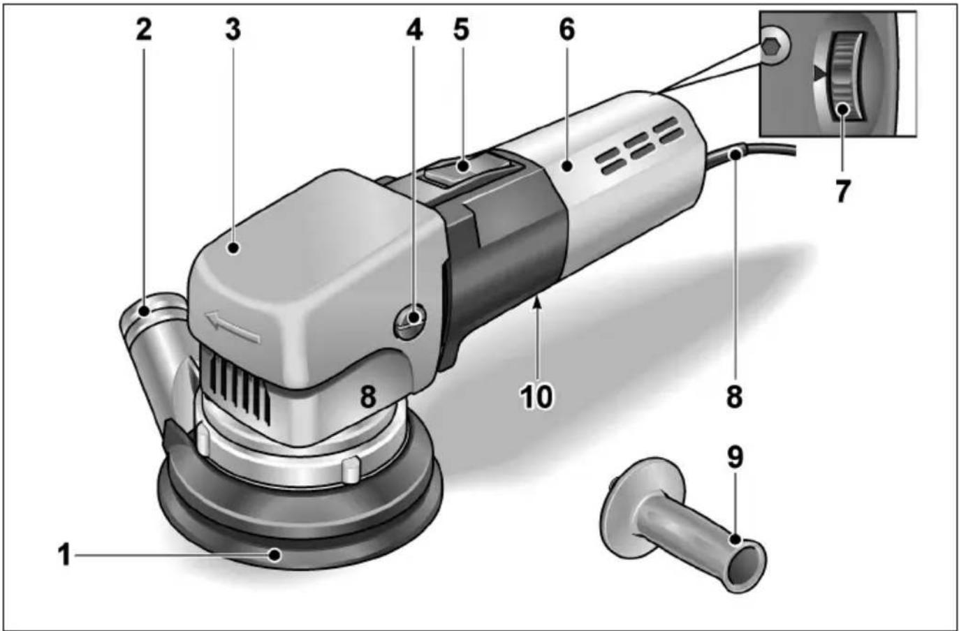
1 Velcro sanding disc
2 Rotatable collar with connection for dust extractor
3 Gear head with handle cover
4 Fastening screw for handle cover
5 O n / O f f s w
6 Motor housing
7 Thumb wheel for controlling the stroke
8 4.0 m power cord with plug
9 H a n d l e
10iRating plate * h
* not visible
Operating instructions

WARNING!
Before performing any work on the electric power tool, pull out the mains plug.
Before switching on the power tool
■ Unpack the electric power tool and check that no parts are missing or damaged.
■ Attach sandpaper.
■ Fit dust catcher.
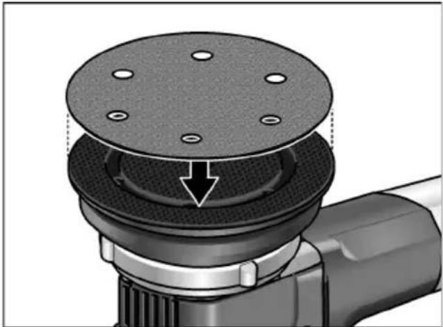
Attaching or changing sandpaper
The sanding plate has Velcro fasteners and is therefore designed exclusively for use with Velcro sandpaper.
■ Pull out the mains plug.
■ Remove attached Velcro sandpaper (optional).
■ Remove any coarse debris from the sanding plate.
natural_image
Mechanical component with a circular base and mounting holes, showing a mechanical assembly (no text or symbols visible)■ Attach new Velcro sandpaper.
Attach the Velcro sandpaper in exact alignment with the holes in the sanding plate.
Attach the Velcro sandpaper by gently pressing it against the Velcro fasteners on the base of the sanding disc.
Dust extractor
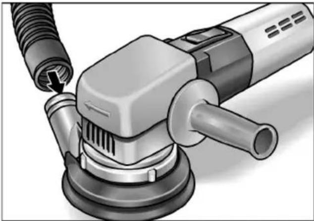
Use the electric power tool only with an extractor. This will prevent high dust loads in the working air and coarse debris at the workplace. The grinding dust is extracted directly from the point of abrasion through the extraction channels in the sanding plate.

NOTE
To prevent the power tool from sticking to the surface of the workpiece, set the suction power on the extractor to a correspondingly low level.
natural_image
Illustration of a power tool with attached pipe and screw, showing mechanical components (no text or symbols)■ Attach extraction hose to the connector (∅ 28 mm). If required, use an appropriate adapter.
■ Connect extraction hose to the dust extraction system.
Follow the operating instructions for the dust extraction system!
Check the attachment!
Switching the electric power tool on and off
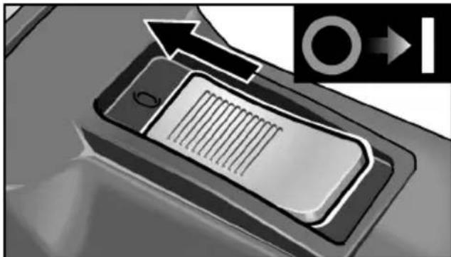
Brief operation without engaged switch rocker:
natural_image
Close-up of a car interior panel with a right-handled arrow and circular symbol (no readable text or symbols)■ Push the switch rocker forwards and hold in position.
■ To switch off the power tool, release the switch rocker.
Continuous operation with engaged switch rocker:

CAUTION!
Following a power failure, the switched onelectric power tool will start running again.
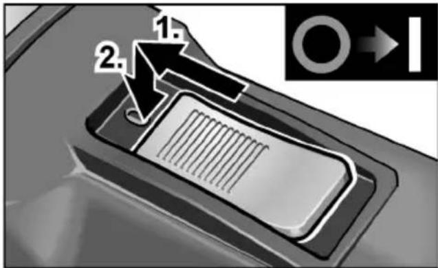
■ Push the switch rocker forwards and engage by pressing the front end.
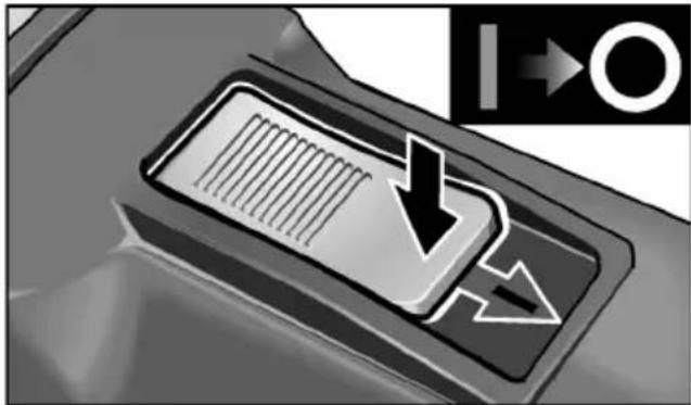
Switch off the machine:
natural_image
Close-up of a car air vent with a down arrow and directional arrows (no text or symbols)■ To switch off the power tool, release the switch rocker by pressing the rear end.
Speed control
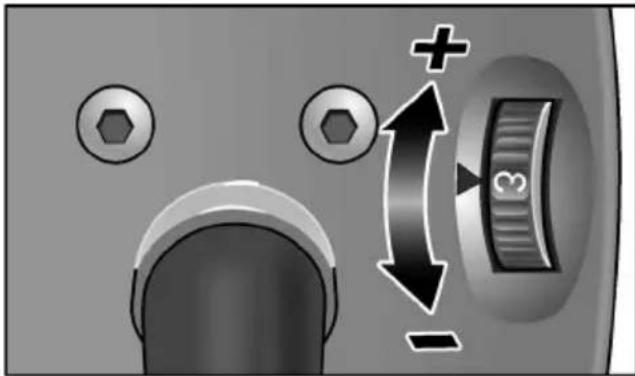
■ The thumb wheel can be used to steplessly vary the speed from 1 (low) to 6 (high) even while the power tool is running.
As a result, the grinding speed can be optimally adjusted to the particularly material and the working conditions.
Operating instructions

NOTE
When the power tool is switched off, thegrinding tool continues running briefly.
natural_image
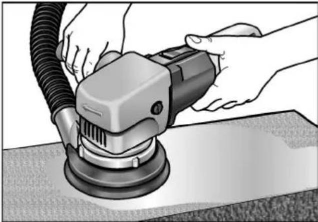
Person using a power tool on a workbench, no visible text or symbols■ Hold the sander with both hands.
■ Do not overload the sander by applying excessive pressure. An excessive increase in the contact pressure will not increase the grinding performance, but will increase the wear on the electric power tool and the sanding tool.
For further information on the manufacturer's products go to www.flex-tools.com.
Maintenance and care

WARNING!
Before performing any work on the electric power tool, pull out the mains plug.
Cleaning
■ Regularly clean the power tool and ventilation slots.
■ Using dry compressed air, regularly blow out the housing interior and motor through the ventilation slots.
Carbon brushes
The electric power tool features cut-off carbon brushes.
When the cut-off carbon brushes reach their wear limit, the electric power tool switches off automatically.

NOTE
Use only original parts supplied by the manufacturer for replacement purposes. If non-original parts are used, the guarantee obligations of the manufacturer will be deemed null and void.
Housing

NOTE
Do not loosen the screws on the housing head. Non-compliance will deem the guarantee obligations of the manufacturer null and void.
Repairs
Repairs may be carried out by an authorised customer service centre only.
Spare parts and accessories
Sandpaper for different application areas and other accessories can be found in the manufacturer's catalogues.
Exploded drawings and spare-part lists can be found on our homepage: www.flex-tools.com
Disposal information

WARNING!
Render redundant power tools unusable byremoving the power cord.

EU countries only
Do not throw electric power tools into the household waste!
In accordance with the European Directive 2012/19/EC on Waste Electrical and Electronic Equipment and transposition into national law used electric power tools must be collected separately and recycled in an environmentally friendly manner.

NOTE
Please ask your dealer about disposal options!
CE-Declaration of Conformity
We declare under our sole responsibility that the product described under “Technical specifications” conforms to the following standards or normative documents:
EN 60745 in accordance with the regulations of the directives 2004/108/EC (until 19.04.2016), 2014/30/EU (from 20.04.2016), 2006/42/EC, 2011/65/EC.
Responsible for technical documents:
Manager Research & Development (R & D)
Klaus Peter WeinperEckhard Rühle Head of Quality Department (QD)
29.06.2015
Exemption from liability
The manufacturer and his representative are not liable for any damage and lost profit due to interruption in business caused by the product or by an unusable product.
The manufacturer and his representative are not liable for any damage which was caused by improper use of the power tool or by use of the power tool with products from other manufacturers.
Table des matières
natural_image
Mechanical component with a circular base and mounting holes, showing a mechanical assembly (no text or symbols visible)natural_image
Illustration of a power tool with meshing and a probe inserted (no text or symbols)natural_image
Close-up of a smartphone screen with an arrow pointing to it, showing no visible text or symbols.natural_image
Close-up of a car's air vent with a downward arrow and directional arrows, no visible text or symbols.natural_image
Illustration of hands using a power tool on a workbench (no text or symbols visible)Manager Research & Development (R & D)
Klaus Peter WeinperEckhard F Head of Quality Department (QD)
29.06.2015
natural_image
Mechanical component with a circular base and mounting holes, showing internal structure (no text or symbols)natural_image
Illustration of a mechanical power tool with a threaded end and handle, no text or symbols presentnatural_image
Close-up of a car interior panel with a door and ventilation slots, showing an arrow indicating direction (no text or symbols)natural_image
Close-up of a car air vent with a downward arrow and directional arrows indicating airflow or flow (no text or symbols)natural_image
Illustration of hands using a power tool on a textured surface (no text or symbols visible)Manager Research & Development (R & D)
Klaus Peter WeinperEckhard Head of Quality Department (QD)
29.06.2015
natural_image
Mechanical component diagram showing a circular pad or fixture with mounting holes and a directional arrow indicating movement (no text or symbols present)natural_image
Illustration of a power tool with attached screw and pipe assembly (no text or symbols)natural_image
Close-up of a car front panel with a right-handled arrow and circular icon (no text or symbols)natural_image
Close-up of a car's air vent with a down arrow and directional arrows (no text or symbols)natural_image
Illustration of hands using a power tool on a workbench (no text or symbols visible)Manager Research & Development (R & D)
Head of Quality Department (QD)
natural_image
Close-up of a mechanical component with a circular top and threaded base, showing a bolted joint and a downward arrow indicating motion (no text or symbols)natural_image
Close-up of a mechanical power tool with a threaded pipe fitting and a circular base (no text or symbols visible)natural_image
Close-up of a car interior showing a mounted device with a grid pattern and directional arrows (no text or symbols)natural_image
Close-up of a car air vent with a downward arrow and directional arrows indicating airflow or flow (no text or symbols)natural_image
Illustration of hands using a power tool on a workbench (no text or symbols visible)Manager Research & Development (R & D)
Klaus Peter WeinperEckhard F Head of Quality Department (QD)
natural_image
Mechanical component diagram showing a bolted joint with a circular base and arrow indicating force or movement (no text or symbols)natural_image
Illustration of a power tool with attached screw and handle (no text or symbols)natural_image
Close-up of a car door handle with a grid and arrow indicator (no text or symbols)natural_image
Close-up of a car's air vent with a black arrow indicating airflow or flow direction (no text or symbols)natural_image
Illustration of hands using a power tool on a workbench (no text or symbols visible)Klaus Peter WeinperEckhard F
Manager Research & Development (R & D)
Head of Quality Department (QD)
natural_image
Mechanical component diagram showing a presser blade with mounting holes and a central rotating knob (no text or symbols)natural_image
Close-up of a mechanical power tool with a threaded end and pipe fitting (no visible text or symbols)natural_image
Close-up of a car air vent with a mounted sensor or sensor component, showing airflow direction (no text or symbols)■ Skub vippekontakten fremad og hold den fast.
■ Slip vippekontakten for at slukke.
Konstant drift med indgreb:

FORSIGTIG!
natural_image
Close-up of a car's air vent with a downward arrow and directional arrows, no visible text or symbols.■ Frigør vippekontakten ved at trykke på bagerste ende for at slukke.
Regulering af omdrejningstal

natural_image
Illustration of hands using a power tool on a textured surface (no text or symbols visible)Manager Research & Development (R & D)
Klaus Peter WeinperEckhard F Head of Quality Department (QD)
1 Slipetallerken med borrelås
2 Dreibar mansjett med tilkoplingsstuss for støvsuger
3 Girhode med gripehette
4 Festeskrue for gripehette
5 Bryter for inn-/utkopling
natural_image
Mechanical component diagram showing a circular pad lid with mounting holes and a mechanical shaft (no text or symbols)natural_image
Illustration of a power tool with attached pipe and screw, showing mechanical components (no text or symbols)■ Avsugningsslangen festes i tilkoplingsstussen (∅ 28 mm). Om nødvendig må det brukes en passende adapter.
■ Avsugingsslangen tilkoples til avsugingsanlegget.
Ta hensyn til betjeningsveiledningen for avsugingsanlegget! Kontroller festet!
natural_image
Close-up of a car's front panel with a scroll and directional arrow, no visible text or symbolsnatural_image
Close-up of a car's air vent with a black arrow indicating airflow or flow direction (no text or symbols)natural_image
Illustration of hands using a power tool on a workbench (no text or symbols visible)Manager Research & Development (R & D)
Klaus Peter WeinperEckhard F Head of Quality Department (QD)
natural_image
Mechanical component with a circular base and mounting holes, showing a mechanical assembly (no text or symbols visible)natural_image
Close-up of a mechanical power tool with a threaded pipe and meshing base (no visible text or symbols)natural_image
Close-up of a car door handle with a grid pattern and directional arrow (no text or symbols)natural_image
Close-up of a car's air vent with a downward arrow and directional arrows, no visible text or symbols.natural_image
Illustration of hands using a power tool on a workbench (no text or symbols visible)Manager Research & Development (R & D)
Klaus Peter WeinperEckhard F Head of Quality Department (QD)
natural_image
Mechanical component diagram showing a bolted assembly with a circular base and threaded shaft (no text or symbols)natural_image
Illustration of a power tool with attached pipe and screw, showing mechanical components (no text or symbols)natural_image
Close-up of a mobile phone interface with a scroll and directional arrow (no text or symbols)natural_image
Close-up of a car interior panel with a downward arrow and grid pattern, no visible text or symbolsnatural_image
Illustration of hands using a power tool on a workbench (no text or symbols visible)Manager Research & Development (R & D)
Klaus Peter WeinperEckhard F Head of Quality Department (QD)
natural_image
Close-up of a mechanical component with a circular top and threaded base, showing internal structure and mounting holes (no text or symbols visible)natural_image
Illustration of a power tool with meshing and a curved pipe fitting (no text or symbols)natural_image
Close-up of a car door handle with a grid pattern and directional arrow (no text or symbols)natural_image
Close-up of a car's air vent with a black arrow pointing downward and a white arrow pointing upward (no text or symbols)natural_image
Illustration of hands using a power tool on a textured surface (no text or symbols visible)Manager Research & Development (R & D)
Head of Quality Department (QD)
29.06.2015
natural_image
Mechanical component with a circular base and mounting holes, showing a mechanical assembly (no text or symbols visible)natural_image
Illustration of a power tool with attached pipe and screw, showing mechanical components (no text or symbols)natural_image
Close-up of a car door handle with a grid pattern and directional arrow (no text or symbols)natural_image
Close-up of a car's air vent with a downward arrow and grid pattern, no visible text or symbolsnatural_image
Illustration of hands using a power tool on a workbench (no text or symbols visible)2006/42/WE, 2011/65/WE.
Manager Research &
Development (R & D)
Klaus Peter WeinperEckhard F
Head of Quality
Department (QD)
natural_image
Mechanical component with a circular base and mounting holes, showing a mechanical assembly (no text or symbols visible)natural_image
Illustration of a power tool with attached screw and pipe (no text or symbols)natural_image
Close-up of a car door handle with a grid pattern and directional arrow (no text or symbols)natural_image
Close-up of a car's air vent with a downward arrow and grid pattern, no visible text or symbolsnatural_image
Illustration of hands using a power tool on a textured surface (no text or symbols visible)Manager Research & Development (R & D) 29.06.2015
Klaus Peter WeinperEckhard F Head of Quality Department (QD)
natural_image
Close-up of a mechanical component with a circular top and threaded base, showing a bolted joint and a downward arrow indicating a force or direction (no text or symbols present)natural_image
Close-up of a mechanical power tool with a threaded end and nozzle (no visible text or symbols)natural_image
Close-up of a car front panel with a right-handled arrow and circular arrow indicator (no text or symbols)natural_image
Close-up of a car air conditioner panel with a downward arrow and directional arrows (no text or symbols)natural_image
Illustration of hands using a power tool on a textured surface (no text or symbols visible)Manager Research & Development (R & D)
Klaus Peter WeinperEckhard Rühle Head of Quality Department (QD)
1 Brúsny tanier so suchým zipsom 6 K r y t m o t o r
natural_image
Close-up of a mechanical component with a circular base and mounting holes, showing a downward arrow indicating a process or assembly (no text or symbols present)■ Nasad'te nový brúsny papier so suchým zipsom. Umiestnite brúsny papier so suchým zipsom tak, aby sa presne zhodoval s otvormi na brúsnej doske.
natural_image
Illustration of a power tool with a hose and meshing base (no text or symbols)■ Upevnite odsávaciu hadicu na pripojovacie hrdlo ( 28 mm). V prípade potreby použite vhodný adaptér.
■ Pripojte odsávaciu hadicu na odsávacie zariadenie.
Dodržiavajte návod na obsluhu odsávacieho zariadenia! Skontrolujte upevnenie!
natural_image
Close-up of a car door handle with a grid pattern and directional arrow (no text or symbols)natural_image
Close-up of a car's front panel with a downward arrow and directional symbol (no readable text or labels)natural_image
Illustration of hands using a power tool on a workbench (no text or symbols visible)Manager Research & Development (R & D)
Klaus Peter WeinperEckhard F Head of Quality Department (QD)
29.06.2015
natural_image
Close-up of a mechanical component with a circular base and mounting holes, showing a downward arrow indicating a process or assembly (no text or symbols present)natural_image
Close-up of a mechanical power tool with a threaded end and central hub (no visible text or symbols)natural_image
Close-up of a car interior panel with a handle and arrow indicator (no readable text or symbols)natural_image
Close-up of a car's air vent with a downward arrow and directional arrows (no text or symbols)natural_image
Illustration of hands using a power tool on a workbench (no text or symbols visible)Manager Research & Development (R & D)
Klaus Peter WeinperEckhard F
Head of Quality Department (QD)
29.06.2015
natural_image
Close-up of a mechanical component with a circular base and mounting holes, showing a downward arrow indicating a process or assembly (no text or symbols present)natural_image
Illustration of a mechanical power tool with a threaded base and handle (no text or symbols)natural_image
Close-up of a mobile phone interface with a scroll and directional arrow (no text or symbols)natural_image
Close-up of a car's air vent with a down arrow and directional arrows (no text or symbols)natural_image
Illustration of hands using a power tool on a workbench (no text or symbols visible)Manager Research & Development (R & D)
Klaus Peter WeinperEckhard F Head of Quality Department (QD)
natural_image
Close-up of a mechanical component with a circular base and mounting holes, showing a downward arrow indicating a process or assembly (no text or symbols present)natural_image
Close-up of a mechanical power tool with a threaded end and handle, no visible text or symbolsnatural_image
Close-up of a car interior panel with a handle and ventilation slots, showing an arrow indicating direction (no text or symbols)natural_image
Close-up of a car's air vent with a downward arrow and directional indicator (no text or symbols)natural_image
Illustration of hands using a power tool on a workbench (no text or symbols visible)Manager Research & Development (R & D)
Klaus Peter WeinperEckhard F Head of Quality Department (QD)
natural_image
Mechanical component with a circular base and mounting holes, showing a downward force arrow (no text or symbols)natural_image
Illustration of a power tool with attached pipe and screw, showing mechanical components (no text or symbols)natural_image
Close-up of a car air vent with a mounted grille and directional arrow (no text or symbols)natural_image
Close-up of a car air vent with a black arrow pointing to the vent, no visible text or symbolsnatural_image
Illustration of hands using a power tool on a workbench (no text or symbols visible)Manager Research & Development (R & D)
Klaus Peter WeinperEckhard F
Head of Quality
Department (QD)
29.06.2015



- Symbols used in this manual
- WARNING!
- CAUTION!
- NOTE
- Symbols on the power tool
- For your safety
- Intended use
- Safety instructions for sander
- Additional safety instructions
- Noise and vibration
- Overview
- Operating instructions
- Before switching on the power tool
- Attaching or changing sandpaper
- Dust extractor
- Switching the electric power tool on and off
- Continuous operation with engaged switch rocker:
- Speed control
- Maintenance and care
- Cleaning
- Carbon brushes
- Housing
- Repairs
- Spare parts and accessories
- Disposal information
- CE-Declaration of Conformity
- Exemption from liability
- Table des matières
- Konstant drift med indgreb:
- FORSIGTIG!
- Regulering af omdrejningstal
Brand : Flex
Model : X 1107 VE
Category : Sander