EDGE-5500Q - Industrial machine MSW - Free user manual and instructions
Find the device manual for free EDGE-5500Q MSW in PDF.

| Product type | Industrial edge banding machine |
| Model | MSW-EDGE-5500Q |
| Rated voltage | 400 V~ / 50 Hz |
| Rated power | 5300 W |
| Weight | 356 kg |
| Heating temperature | Up to 200 °C (recommended 120-180 °C) |
| Required air pressure | 0.4 - 0.6 MPa |
| Minimum inner curve diameter | 40 mm |
| Main functions | Edge banding with hot melt glue, cutting, trimming, speed control |
| Compatible materials | Veneer, PVC, ABS |
| Safety | Emergency stop, guards, safety switch, grounding |
| Maintenance | Regular cleaning, fuse check, cable inspection |
| Cleaning | Soft, slightly damp cloth, non-corrosive products |
| Spare parts and repairability | Repairs only by manufacturer's after-sales service |
| Disposal | Do not dispose with household waste, recycle via WEEE collection points |
| Warranty and support | Contact manufacturer via info@expondo.com |
| General information | Indoor use, ambient temperature max 40°C, humidity <85% |
Frequently Asked Questions - EDGE-5500Q MSW
User questions about EDGE-5500Q MSW
0 question about this device. Answer the ones you know or ask your own.
Ask a new question about this device
Download the instructions for your Industrial machine in PDF format for free! Find your manual EDGE-5500Q - MSW and take your electronic device back in hand. On this page are published all the documents necessary for the use of your device. EDGE-5500Q by MSW.
USER MANUAL EDGE-5500Q MSW
natural_image
Industrial conveyor belt system with roller rollers and yellow tape, no visible text or symbolsnatural_image
Close-up of a mechanical assembly with visible gears and components, alongside a green panel on a red surface (no text or symbols)natural_image
Close-up of a precision optical instrument with mechanical components and wiring (no visible text or symbols)natural_image
Close-up of a laboratory setup with mechanical components and tubing (no visible text or symbols)natural_image
Industrial machine with blue internal panel and yellow conveyor belt (no visible text or symbols)natural_image
Close-up of a mechanical assembly with a yellow clamp and black knob, no visible text or symbolsAbbildung 1

natural_image
Industrial machine with rollers and a gray panel on the side, no visible text or symbolsAbbildung 2

natural_image
Close-up of a laboratory apparatus with a yellow cross-shaped clamp and transparent tubing, no visible text or symbols.Abbildung 3

natural_image
Close-up of industrial machinery components with blue and white surfaces, no visible text or symbolsAbbildung 4
This User Manual has been translated using machine translation. We have made every effort to ensure the translation is accurate, but please note that automated translations are not perfect and are not meant to replace human translators. The official version of the User Manual is in English. Any differences between the translated version and the original English are not legally binding. If you have any questions about the accuracy of the translation, please refer to the English version, which is the official reference. More language versions are available upon request via info@expondo.com.
Technical data
| Parameter description Parameter value | |
| Product name | Industrial edge banding machine |
| Model | MSW-EDGE-5500Q |
| Rated voltage [V~] / frequency [Hz] | 400/50 |
| Rated power [W] | 5300 |
| Weight [kg] | 356 |
1. General description
The user manual is designed to assist in the safe and trouble-free use of the device. The product is designed and manufactured in accordance with strict technical guidelines, using state-of-the-art technologies and components. Additionally, it is produced in compliance with the most stringent quality standards.
DO NOT USE THE DEVICE UNLESS YOU HAVE THOROUGHLY READ AND UNDERSTOOD THIS USER MANUAL.
To increase the product life of the device and to ensure trouble-free operation, use it in accordance with this user manual and regularly perform maintenance tasks. The technical data and specifications in this user manual are up to date. The manufacturer reserves the right to make changes associated with quality improvement. The device is designed to reduce noise emission risks to a minimum, taking into account technological progress and noise reduction opportunities.
Legend

The product satisfies the relevant safety standards.

Read instructions before use.

The product must be recycled.

WARNING! or CAUTION! or REMEMBER! Applicable to the given situation. (general warning sign)

Wear a dust mask (respiratory tract protection).

Use guard.

ATTENTION! Electric shock warning!

ATTENTION! Rotating parts, entanglement hazard!

WARNING! Toxic substances, danger of poisoning!
ATTENTION! Hand crush hazard!
Emergency stop!
ATTENTION! Hot surface, risk of burns!
Only use indoors.

PLEASE NOTE! Drawings in this manual are for illustration purposes only and in some details may differ from the actual product.
2. Usage safety

ATTENTION! Read all safety warnings and all instructions. Failure to follow the warnings and instructions may result in electric shock, fire and/or serious injury or even death.
The terms "device" or "product" are used in the warnings and instructions to refer to: Industrial edge banding machine
2.1. Electrical safety
a) The plug must fit the socket. Do not modify the plug in any way. Using original plugs and matching sockets reduces the risk of electric shock.
b) Avoid touching earthed elements such as pipes, heaters, boilers and refrigerators. There is an increased risk of electric shock if the earthed device is exposed to rain, comes into direct contact with a wet surface or is operating in a damp environment. Water getting into the device increases the risk of damage to the device and of electric shock.
c) Do not touch the device with wet or damp hands.
d) Use the cable only for its designated use. Never use it to carry the device or to pull the plug out of a socket. Keep the cable away from heat sources, oil, sharp edges or moving parts. Damaged or tangled cables increase the risk of electric shock.
e) Do not use the device if the power cord is damaged or shows obvious signs of wear. A damaged power cord should be replaced by a qualified electrician or the manufacturer's service centre.
f) To avoid electric shock, do not immerse the cord, plug or device in water or other liquids. Do not use the device on wet surfaces.
g) ATTENTION! DANGER TO LIFE! While cleaning, never immerse the device in water or other liquids.
h) Do not use in very humid environments or in the direct vicinity of water tanks.
i) Before the first use, please check whether the main voltage type and current comply with the indicated data on the type plate.
2.2. Safety in the workplace
a) Make sure the workplace is clean and well lit. A messy or poorly lit workplace may lead to accidents. Try to think ahead, observe what is going on and use common sense when working with the device.
b) If you discover damage or irregular operation, immediately switch the device off and report it to a supervisor without delay.
c) If there are any doubts as to the correct operation of the device, contact the manufacturer's support service.
d) Only the manufacturer's service point may repair the device. Do not attempt any repairs independently!
e) In case of fire, use a powder or carbon dioxide (CO2) fire extinguisher (one intended for use on live electrical devices) to put it out.
f) Children or unauthorised persons are forbidden to enter a work station. A distraction may result in loss of control over the device.
g) Use the device in a well-ventilated space.
h) The device produces dust and debris during operation. It is important to protect bystanders from their harmful effects.
i) Use the "EMERGENCY STOP" if there is a risk of injury or death, accident or damage.
j) Regularly inspect the condition of the safety labels. If the labels are illegible, they must be replaced.
k) Please keep this manual available for future reference. If this device is passed on to a third party, the manual must be passed on with it.
I) Keep packaging elements and small assembly parts in a place not available to children.
m) Keep the device away from children and animals.
n) If this device is used together with another equipment, the remaining instructions for use shall also be followed.

Remember! When using the device, protect children and other bystanders.
2.3. Personal safety
a) Do not use the device when tired, ill or under the influence of alcohol, narcotics or medication which can significantly impair the ability to operate the device.
b) The machine may be operated by physically fit persons who are able to handle the machine, are properly trained, who have reviewed this operating manual and have received training in occupational health and safety.
c) When working with the device, use common sense and stay alert. Temporary loss of concentration while using the device may lead to serious injuries.
d) Use personal protective equipment as required for working with the device, specified in section 1 "Legend". The use of correct and approved personal protective equipment reduces the risk of injury.
e) To prevent the device from accidentally switching on, make sure the switch is on the OFF position before connecting to a power source.
f) Do not overestimate your abilities. When using the device, keep your balance and remain stable at all times. This will ensure better control over the device in unexpected situations.
g) Do not wear loose clothing or jewellery. Keep hair, clothes and gloves away from moving parts. Loose clothing, jewellery or long hair may get caught in moving parts.
h) Remove all adjusting tools or spanners before turning the device on. A tool or spanner left in the revolving part of the device may cause injury.
i) The device is not a toy. Children must be supervised to ensure that they do not play with the device.
j) If suction is to be connected to the device, check all connections and make sure they are tight. Using a dedusting system may reduce the risks associated with dust.
2.4. Safe device use
a) Do not overload the device. Use the appropriate tools for the given task. A correctly-selected device will perform the task for which it was designed better and in a safer manner.
b) Do not use the device if the "ON/OFF" switch does not function properly (does not switch the device on and off). Devices which cannot be switched on and off using the ON/OFF switch are hazardous, should not be operated and must be repaired.
c) Make sure the plug is disconnected from the socket before attempting any adjustments, accessory replacements or before putting the device aside. Such precautions will reduce the risk of accidentally activating the device.
d) When not in use, store in a safe place, away from children and people not familiar with the device who have not read the user manual. The device may pose a hazard in the hands of inexperienced users.
e) Keep the device in perfect technical condition. Before each use check for general damage, especially check moving components for cracked parts or elements, and for any other conditions which may impact the safe operation of the device. If damage is discovered, hand over the device for repair before use.
f) Keep the device out of the reach of children.
g) To ensure the operational integrity of the device, do not remove factory-fitted guards and do not loosen any screws.
h) When transporting and handling the device between the warehouse and the destination, observe the occupational health and safety principles for manual transport operations which apply in the country where the device will be used.
i) Avoid situations where the device stops working during use due to excessive loading. This may result in overheating of the drive elements and damage to the device.
j) Do not touch articulated parts or accessories unless the device has been disconnected from the power source.
k) Do not move, adjust or rotate the device in the course of work.
I) Do not leave this appliance unattended while it is in use.
m) Clean the device regularly to prevent stubborn grime from accumulating.
n) Do not work on two workpieces at the same time.
o) It is forbidden to interfere with the structure of the device in order to change its parameters or construction.
p) Keep the device away from sources of fire and heat.
q) Do not cover the ventilation openings!
r) NOTE: During operation, some elements of the device become very hot – scalding hazard!
s) Use protective glasses. When working in a dusty environment, additionally wear a dust mask.
t) Keep handles dry, clean and free of oil or grease.

ATTENTION! Despite the safe design of the device and its protective features, and despite the use of additional elements protecting the operator, there is still a slight risk of accident or injury when using the device. Stay alert and use common sense when using the device.
3. Use guidelines
Edge banding machine is designed to glue furniture edges with veneer, PVC or ABS materials.
The user is liable for any damage resulting from unintended use of the device.
3.1. Device description
- Emergency stop switch: Emergency stop machine button.
- Power switch: Main power switch.
- Edge banding motor switch: Control the edge banding motor start and stop.
- Trimming switch: Control trimming motor start and stop.
- Thermostat Temperature control adjustment.
- Speed control knob: Adjust the speed of the edge banding.
- Foot control switch: For curved (profiled sheet) edge banding conveyor strips.
- Sliding rail: Auxiliary large sheet support.
- Trimming adjustment knob: Used to adjust the trim height.
- Feed tray: Edge banding tray.
3.2. Preparing for use
APPLIANCE LOCATION
The temperature of environment must not be higher than 40^ C and the relative humidity should be less than 85%. Ensure good ventilation in the room in which the device is being used. There should be at least 10 cm distance between each side of the device and the wall or other objects. The device should always be used when positioned on an even, stable, clean, fireproof and dry surface, and be out of the reach of children and persons with limited mental and sensory functions. Position the device such that you always have access to the power plug. The power cord connected to the appliance must be properly grounded and correspond to the technical details on the product label.
3.3. Device use
When the power is switched on, the thermostat automatically heats up in a self-controlled programme. Do not place the appliance in damp areas. Ensure adequate lighting during operation.
Do not allow children near the veneer machine.
Do not wear a scarf, loose cuff, exposed necklace or any loose clothing or bracelets - these can be pulled into the machine.
Make sure the switch is in the "Stop-OFF" position before turning on the power.
Be careful! The melter can reach a high temperature of 200 degrees. Do not touch the heating area around the melting pot.
When using the melting pot, it is recommended to hold the machine with both hands.
Before starting work, ensure that the wire length is sufficient and does not interfere with the work.
Do not touch flammable or explosive materials.
Avoid rooms with high humidity and it is prohibited to use the device outdoors.
Harmful gases may be produced during use, use the device in a well-ventilated room or with an activated carbon mask.
Switch off the heating switch and the power switch when finished working.
Clean the unit of any excess hot melt adhesive at any time.
The machine should be kept clean.
Wood and materials should be stored at room temperature.
When the moisture content of the workpiece is too high, the quality of the adhesion will be affected.
When edgebanding, ensure adequate pressure on the workpiece, insufficient pressure will affect the quality of the edgebanding.
Hot melt adhesive should be stored in a cool and dry place.
When hot melt glue is cold, do not open the crucible lid or glue adjustment knob to avoid damaging the machine.
Before edge banding, ensure that the hot melt glue in the crucible is already melted as standard.
The diameter of the inner curve must not be less than 40 mm.
It is recommended to use a low-temperature hot-melt adhesive of 120-180°C (the maximum temperature must not exceed 200°C).
Preparation and commissioning
Switch the unit on to a suitable power source, turn on the power switch, the switch indicator will light up and the temperature control gauge will be displayed and the temperature will rise after the self-test.
Adjust the heating temperature in the temperature control chart (the temperature depends on the melting point of the hot melt adhesive, and the unit uses a medium-low temperature hot melt adhesive of 120-180 °C). When the heating reaches the set temperature, the motor switch light will illuminate and press the motor switch to start it. It is recommended to preheat the machine for 10 minutes before sealing the edges before starting the motor to allow the hot melt glue to melt completely.
Insert the air line and adjust the air pressure to 0.4-0.6 MPa (the machine was adjusted before leaving the factory).
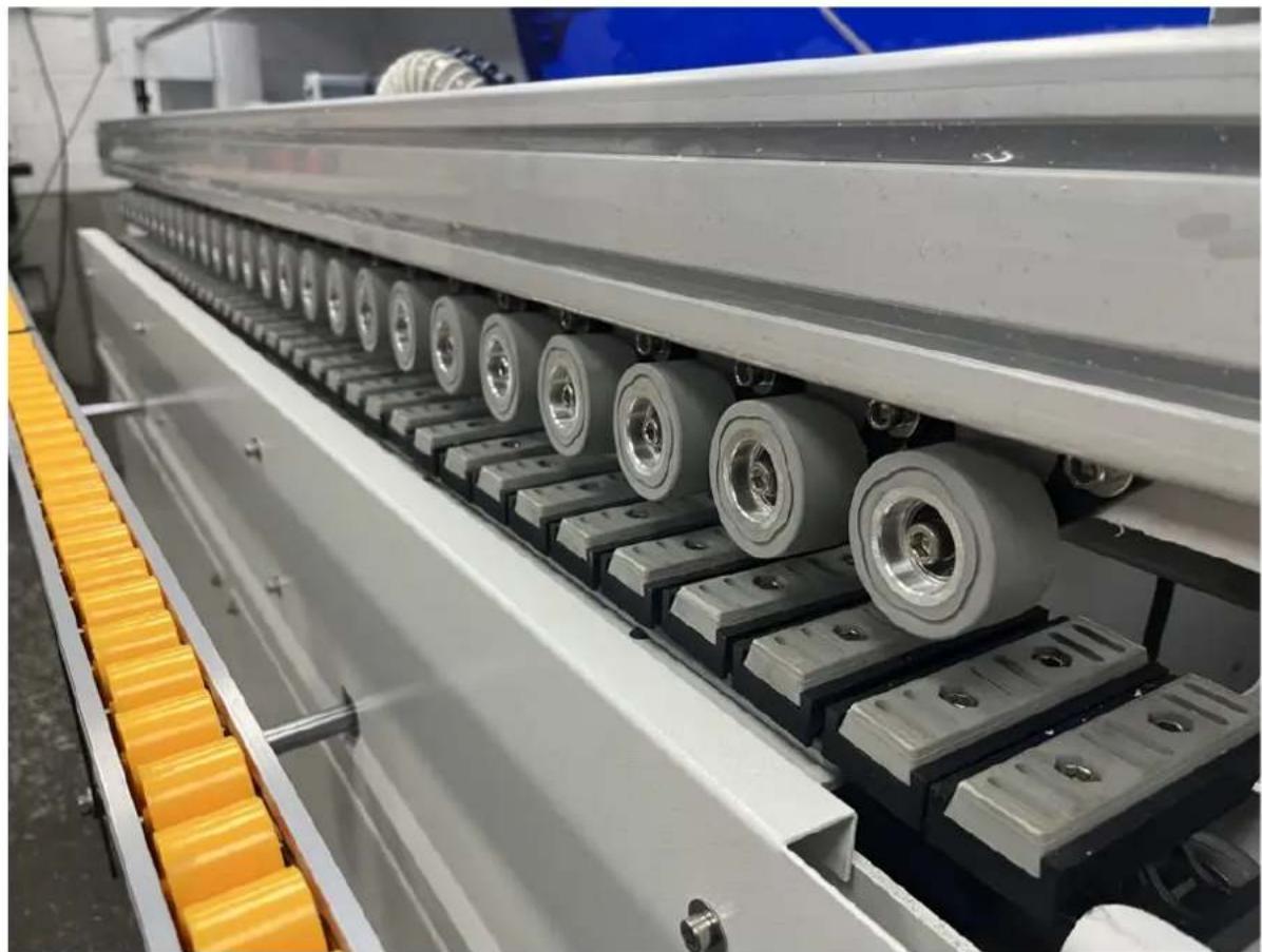
natural_image
Industrial conveyor belt system with rollers and yellow tape, no visible text or symbolsInstall the feeder tray, remove the feeder tray screw, install the bracket in reverse, remove the large hexagon socket screw above the bracket and remove the flat bearing, then place it on the feeder tray between the two flat bearings. The socket head screws are fixed.
natural_image
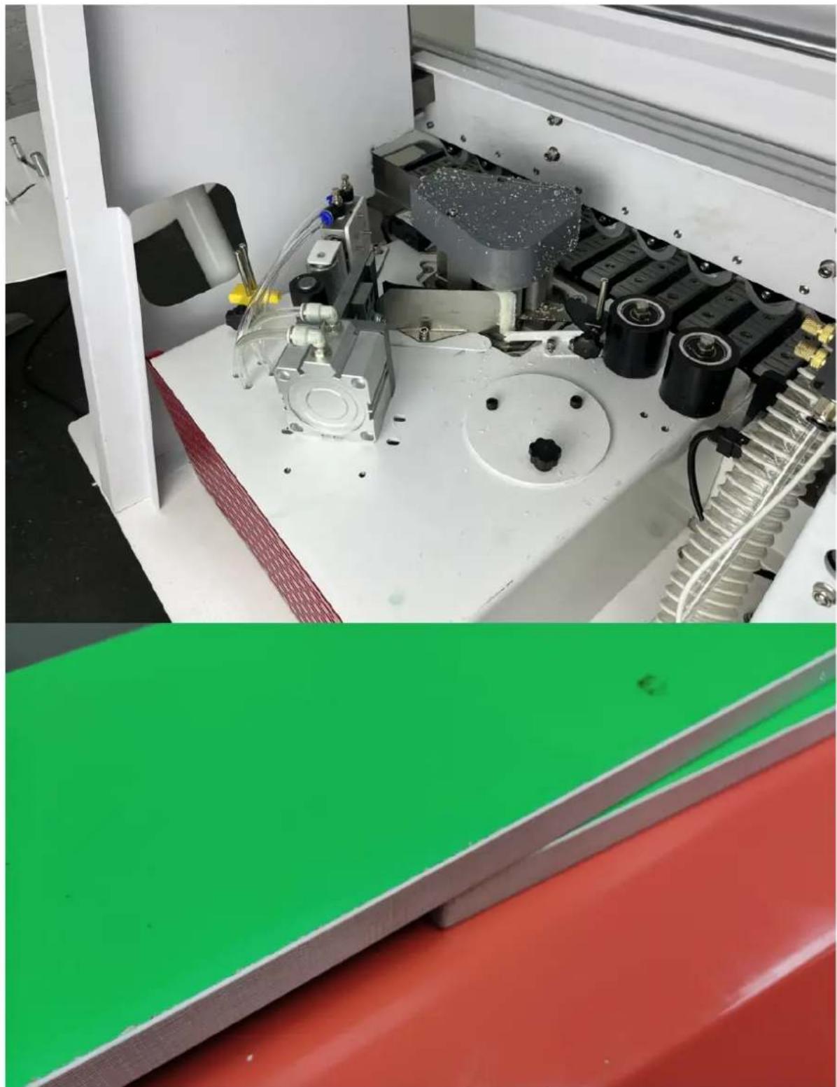
Close-up of a mechanical assembly with visible gears and components, alongside a green panel on a red surface (no text or symbols)A. Adjustment of trimming and cutting edges
- Place the workpiece under the trimming tip, adjust the knob above the trimmer and adjust the distance between the tip and the workpiece.
natural_image
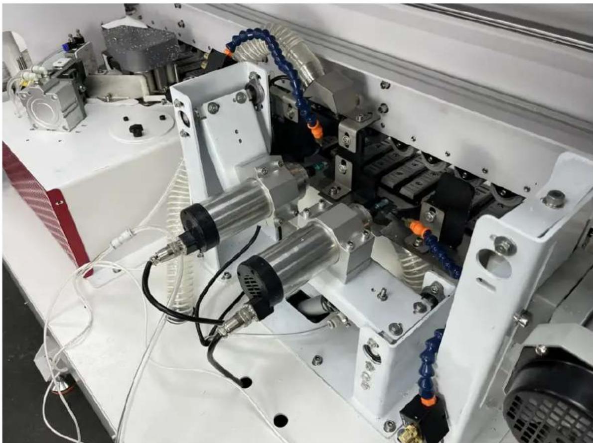
Close-up of a precision optical instrument with visible gears and wiring (no text or symbols)B. Edge banding and trimming operation
1. When the motor switch light is on, press the switch to start the motor and press the trimming motor switch.
2. The edge tape is inserted into the tool holder and into the transmission pulley.

natural_image
Close-up of a laboratory setup with mechanical components and tubing (no visible text or symbols)The edge band needs to be placed between the feed pulleys and inserted into the knife guide groove.
C. The workpiece is placed on the front baffle and pressed against the baffle switch. At this point, the tool holder opens the press wheel and presses the edge belt to feed the rubber. When the edge band reaches the motor wheel through the rubberizing roller, the workpiece is pressed down. To the edge band, maintain a certain lateral force and downforce, so that the sealed workpiece is pressed against the trimming switch and the workpiece is trimmed by the cutting head at a uniform speed.
natural_image
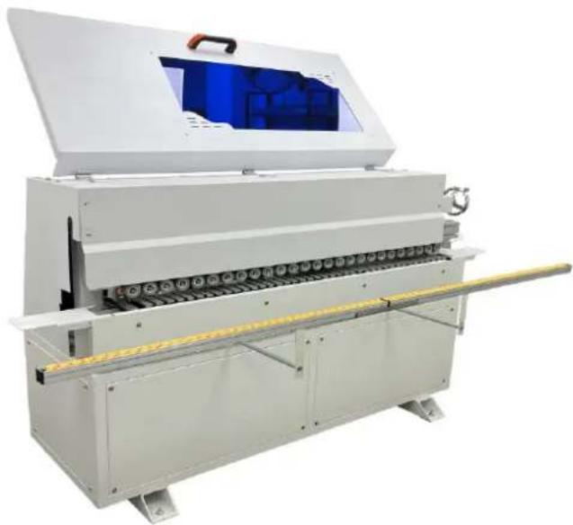
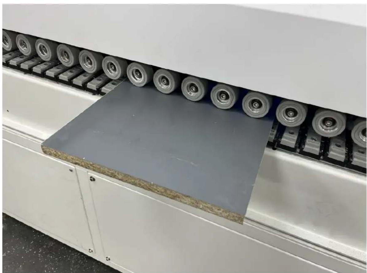
Industrial machine with conveyor belt and blue internal panel (no visible text or symbols)Adjust the height of the edging strip
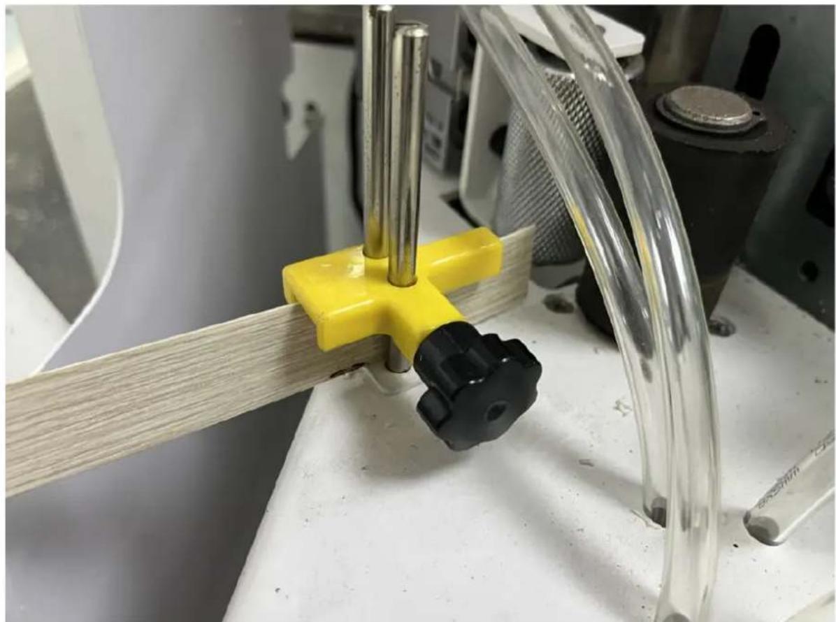
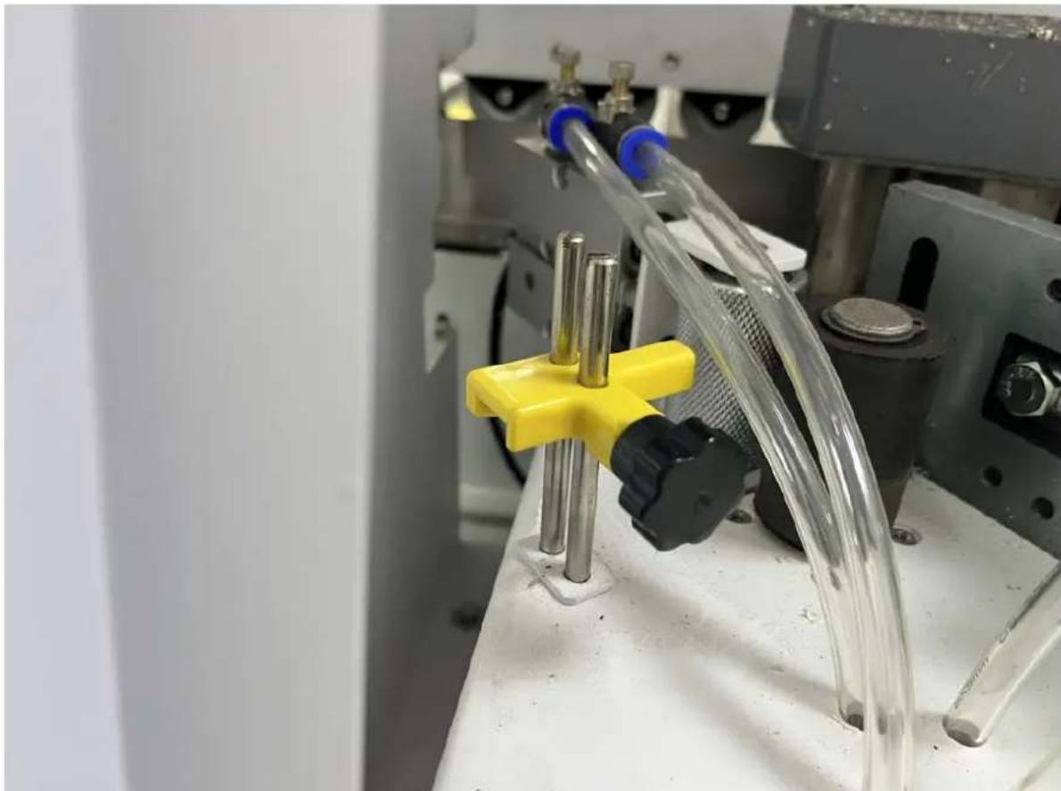
- Loosen the Front Limiter Knob (Figure 1):
- Begin by loosening the knob of the front limiter. This allows for adjustments to be made in positioning or measuring the edge band.
-
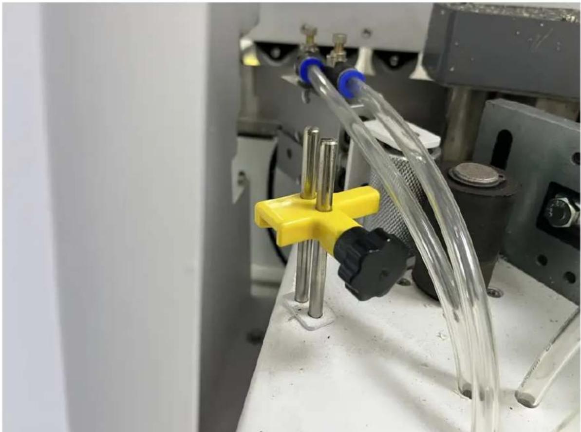
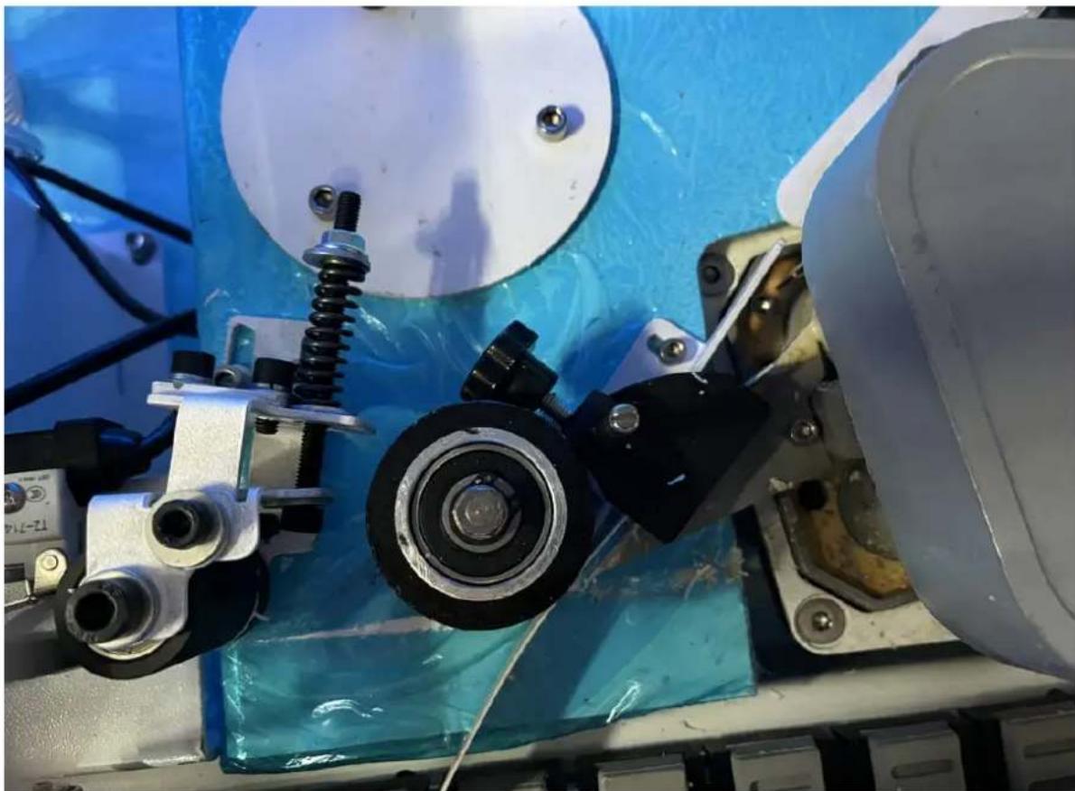
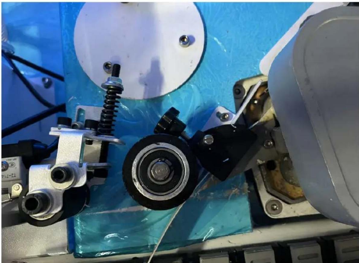
Insert the Edge Band (Figure 2 & Figure 3):
-
Insert the edge band into the machine, specifically into the measuring wing of the height limiter. This device measures the thickness or height of the edge band, ensuring proper alignment and spacing for the application process.
-
Once the edge band is placed correctly, press the lower limiter (this would be a component that ensures the edge band is held in place securely) against the side strip (the actual edge band).
• After positioning, lock the knob to secure the edge band and limiters in place. -
Adjust the Workpiece Height (Figure 4):
-
Referring to the height of the workpiece, place the workpiece underneath the platen wheel (this is the wheel that presses the workpiece onto the main board surface during operation).
- Adjust the platen wheel so that it applies pressure to the workpiece and presses it down to the machine's main board surface. Ensure that there is suitable spacing between the components for the operation to run smoothly.
• To adjust the height or spacing, loosen the adjustable handle (as shown in Figure 4). - Once the appropriate spacing is achieved and the platen wheel is correctly positioned over the workpiece, lock the adjustable handle to secure the settings.
natural_image
Close-up of a mechanical assembly with a yellow clamp and black knob, no visible text or symbolsFigure 1

natural_image
Industrial machine with rollers and a gray panel on the side, no visible text or symbolsFigure 2
natural_image
Close-up of a laboratory apparatus with a yellow cross-shaped clamp and transparent tubing, no visible text or symbols.Figure 3

natural_image
Close-up of industrial machinery components with blue and white surfaces, no visible text or symbolsFigure 4
3 Adjust the glue quantity
When the temperature of the edge banding machine reaches operating temperature, cut a side strip (approximately 20 cm / 8") for testing, adjust the glue quantity knob to the correct amount and allow the melted glue to apply evenly to the edge strip.
Please note that once the hot melt glue has cooled, the adjustment knob cannot be turned as some parts are blocked.
4 Adjusting the thickness of the edge strip: When the side strip is too thin or too soft, adjust the thickness knob and the fixing screw so that the edge seal fits smoothly.
5 Operation.
- When the edge band is attached to the workpiece, apply moderate pressure to increase the sticking effect.
- Confirm that there is no residue in the edge banding machine, and then turn on the start switch of the machine. When the temperature of the hot melt glue in the tank reaches the set temperature, the indicator light of the motor switch button will light up. You can press to switch and allow the melt cycle to accelerate the melting process. Depending on the hot melt adhesive used, wait until the adhesive is fully melted.
- Place the processing plate flat on the panel, ensuring the edge of the board is close to the stroke switch on the stopper. Position the processing plate near the rubber-coated shaft, about 5 cm from the starting point of the shaft. Press the stroke switch with the sheet edge, which activates the edge banding machine.
- The sealing strip is driven to the shaft by cylinder pressure to the feeding pulley. When the edge strip reaches the driving wheel through the rubber-coated shaft, apply moderate pressure to the workpiece and press it to the driving wheel for sealing.
3.4. Cleaning and maintenance
a) Unplug the mains plug and allow the device to cool completely before each cleaning, adjustment or replacement of accessories, or if the device is not being used.
- Wait for the rotating elements to stop.
b) Use only non-corrosive cleaners to clean the surface.
c) After cleaning the device, all parts should be dried completely before using it again.
d) Store the unit in a dry, cool place, free from moisture and direct exposure to sunlight.
e) Do not spray the device with a water jet or submerge it in water.
f) Do not allow water to get inside the device through vents in the housing of the device.
g) Clean the vents with a brush and compressed air.
h) The device must be regularly inspected to check its technical efficiency and spot any damage.
i) Use a soft, damp cloth for cleaning.
j) Do not use sharp and/or metal objects for cleaning (e.g. a wire brush or a metal spatula) because they may damage the surface material of the appliance.
k) Do not clean the device with an acidic substance, agents of medical purposes, thinners, fuel, oils or other chemical substances because it may damage the device.
DISPOSING OF USED DEVICES:
Do not dispose of this device in municipal waste systems. Hand it over to an electric and electrical device recycling and collection point. Check the symbol on the product, instruction manual and packaging. The plastics used to construct the device can be recycled in accordance with their markings. By choosing to recycle you are making a significant contribution to the protection of our environment.
Contact local authorities for information on your local recycling facility.
3.5 Troubleshooting
| Problem | Cause | Solution |
| Machine cannot start | Fuse burn | Replace fuse |
| 1. Incomplete melting of hot melt glue | Open the melting pot cover to check the hot melt glue | |
| 2. Insufficient glue | Adjust gluing knob | |
| 3. The bending stripe deformed | Replace with better edge banding tape | |
| 4. Hot melt glue has not yet been supplied to the glue wheel | Wait a few seconds for hot melt re-flow to melting pot | |
| Glue uneven on the banding tape | Non-parallel adhesive veneer | Re-calibrate the support plate (refer to page) |
| Poor adhesion of the banding tape | 1. Heating for a long time, hot melt glue is deteriorated | Change the hot melt glue |
| 2. Hot melt glue temperature is not the correct temperature | Know the best working temperature for hot melt glue and adjust machine temperature | |
| Banding tape is not level | Twist stroke attached starting point / push slower than speed | The support plate should be flush with the workpiece when pressing. Ensure the edge is not loose. |
| Banding tape is not moving | Wheel or feed wheel skid | Clean the belt pulley and feed wheel |
| Electric start abnormal | Hot melt glue not yet dissolved | Need to re-adjust the temperature, then start running |
| Indicator normal, but motor does not turn | Motor switch damaged | Replace the motor switch, check wiring |
| Abnormal heating | Abnormal heating detection | Contact a professional technician to check for temperature drops or short circuits |
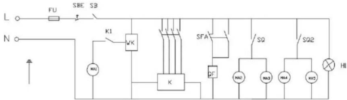
3.6 Circuit diagram
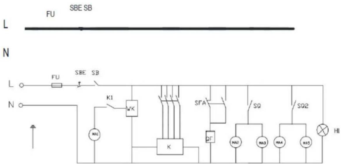
| Symbol | Description | Symbol | Description |
| L | Phase line | MA1 | Edge banding motor |
| N | Neutral line | MA2 | Trimming motor |
| FU | Fuse | MA3 | Trimming motor |
| SBE | Emergency stop switch | K | Relay |
| SB | Power switch button | SFA | Foot switch |
| K1 | Motor switch | SQ | Limit switch |
| WK | Temperature controller | QF | The electromagnetic valve |
| HL | Indicator light |

natural_image
Industrial conveyor belt system with rollers and yellow tape, no visible text or symbolsnatural_image
Close-up of a mechanical assembly with visible gears and components, alongside a green panel on a red surface (no text or symbols)natural_image
Close-up of a precision optical instrument with visible gears and wiring (no text or symbols)natural_image
Close-up of a laboratory setup with mechanical components and tubing (no visible text or symbols)natural_image
Industrial machine with blue internal panel and yellow conveyor belt (no visible text or symbols)natural_image
Close-up of a mechanical assembly with a yellow clamp and black knob, no visible text or symbolsRysunek 1

natural_image
Industrial machine with rollers and a gray panel on the side, no visible text or symbolsRysunek 2
natural_image
Close-up of a laboratory apparatus with transparent tubing, yellow plastic clips, and blue connectors (no visible text or symbols)Rysunek 3

natural_image
Close-up of industrial machinery components with blue and white surfaces, no visible text or symbolsRysunek 4
natural_image
Industrial conveyor belt system with rollers and yellow conveyor belts, no visible text or symbolsnatural_image
Close-up of a mechanical assembly with visible gears and components, alongside a green panel on a red surface (no text or symbols)natural_image
Close-up of a precision optical instrument with mechanical components and wiring (no visible text or symbols)natural_image
Close-up of a laboratory setup with mechanical components and tubing (no visible text or symbols)natural_image
Industrial machine with blue internal panel and yellow conveyor belt (no visible text or symbols)natural_image
Close-up of a mechanical assembly with a yellow clamp and black knob, no visible text or symbolsObrázek 1

natural_image
Industrial machine with rollers and a gray panel on the side, no visible text or symbolsObrázek 2

natural_image
Close-up of a laboratory apparatus with transparent tubing, yellow plastic clips, and blue connectors (no visible text or symbols)Obrázek 3

natural_image
Close-up of industrial machinery components with blue and white surfaces, no visible text or symbolsObrázek 4
natural_image
Industrial conveyor belt system with rollers and yellow conveyor belts (no visible text or symbols)natural_image
Close-up of a mechanical assembly with visible gears and components, alongside a green panel on a red surface (no text or symbols)natural_image
Close-up of a precision optical instrument with mechanical components and wiring (no visible text or symbols)natural_image
Close-up of a laboratory setup with mechanical components and tubing (no visible text or symbols)natural_image
Industrial machine with conveyor belt and blue internal panel (no visible text or symbols)natural_image
Close-up of a mechanical assembly with a yellow clamp and black knob, no visible text or symbolsFigure 1

natural_image
Industrial machine with rollers and a gray panel on the side, no visible text or symbolsFigure 2

natural_image
Close-up of a laboratory apparatus with transparent tubing, yellow plastic clips, and blue connectors (no visible text or symbols)Figure 3

natural_image
Close-up of industrial machinery components with blue and white surfaces, no visible text or symbolsFigure 4
natural_image
Industrial conveyor belt system with rollers and yellow tape, no visible text or symbolsnatural_image
Close-up of a mechanical assembly with visible gears and components, alongside a green panel on a red surface (no text or symbols)natural_image
Close-up of a precision optical instrument with mechanical components and wiring (no visible text or symbols)natural_image
Close-up of a laboratory setup with mechanical components and tubing (no visible text or symbols)natural_image
Industrial machine with conveyor belt and blue internal panel (no visible text or symbols)natural_image
Close-up of a mechanical assembly with a yellow clamp and black knob, no visible text or symbolsFigura 1

natural_image
Industrial machine with rollers and a gray panel on the side, no visible text or symbolsFigura 2

natural_image
Close-up of a laboratory apparatus with transparent tubing, yellow plastic clips, and blue connectors (no visible text or symbols)Figura 3

natural_image
Close-up of industrial machinery components with blue and white surfaces, no visible text or symbolsFigura 4
N

natural_image
Industrial conveyor belt system with rollers and yellow tape, no visible text or symbolsnatural_image
Close-up of a mechanical assembly with visible gears and components, alongside a green panel on a red surface (no text or symbols)natural_image
Close-up of a precision optical instrument with mechanical components and wiring (no visible text or symbols)natural_image
Close-up of a laboratory setup with mechanical components and tubing (no visible text or symbols)natural_image
Industrial machine with blue internal panel and yellow conveyor belt (no visible text or symbols)natural_image
Close-up of a mechanical assembly with a yellow clamp and black knob, no visible text or symbolsFigura 1

natural_image
Industrial machine with rollers and a gray panel on the side, no visible text or symbolsFigura 2

natural_image
Close-up of a laboratory apparatus with transparent tubing, yellow plastic clips, and blue connectors (no visible text or symbols)Figura 3

natural_image
Close-up of industrial machinery components with blue and white surfaces, no visible text or symbolsFigura 4
N
natural_image
Industrial conveyor belt system with rollers and yellow conveyor belts, no visible text or symbolsnatural_image
Close-up of a white industrial machine with mechanical components and a green panel on the side (no visible text or symbols)natural_image
Close-up of a precision optical instrument with mechanical components and wiring (no visible text or symbols)natural_image
Close-up of a laboratory setup with mechanical components and tubing (no visible text or symbols)natural_image
Industrial machine with conveyor belt and blue internal panel (no visible text or symbols)natural_image
Close-up of a mechanical assembly with a yellow clamp and black knob, no visible text or symbols- ábra

natural_image
Industrial machine with rollers and a gray panel on the side, no visible text or symbols- ábra

natural_image
Close-up of a laboratory apparatus with transparent tubing, yellow plastic clips, and blue connectors (no visible text or symbols)- ábra

natural_image
Close-up of industrial machinery components with blue and white surfaces, no visible text or symbols- ábra
OBS! Giftige stoffer, fare for forgiftning!
APPARATETS PLACERING
natural_image
Industrial conveyor belt system with rollers and yellow conveyor belts, no visible text or symbolsnatural_image
Close-up of a mechanical assembly with visible gears and components, alongside a green panel on a red surface (no text or symbols)natural_image
Close-up of a precision optical instrument with mechanical components and wiring (no visible text or symbols)natural_image
Close-up of a laboratory setup with mechanical components and tubing (no visible text or symbols)natural_image
Industrial machine with conveyor belt and blue internal panel (no visible text or symbols)natural_image
Close-up of a mechanical assembly with a yellow clamp and black knob, no visible text or symbolsFigur 1

natural_image
Industrial machine with rollers and a gray panel on the side, no visible text or symbolsFigur 2

natural_image
Close-up of a laboratory apparatus with transparent tubing, yellow plastic clips, and blue connectors (no visible text or symbols)Figur 3

natural_image
Close-up of industrial machinery components with blue and white surfaces, no visible text or symbolsFigur 4
natural_image
Industrial conveyor belt system with rollers and yellow tape, no visible text or symbolsnatural_image
Close-up of a mechanical assembly with visible gears and components, alongside a green panel on a red surface (no text or symbols)natural_image
Close-up of a precision optical instrument with mechanical components and wiring (no visible text or symbols)natural_image
Close-up of a laboratory mechanical setup with transparent tubing, yellow clamps, and blue tubing (no visible text or symbols)natural_image
Industrial machine with conveyor belt and blue internal panel (no visible text or symbols)natural_image
Close-up of a mechanical assembly with a yellow clamp and black knob, no visible text or symbolsKuva 1
natural_image
Industrial machine with rollers and a gray panel on the side, no visible text or symbolsKuva 2

natural_image
Close-up of a laboratory apparatus with transparent tubing, yellow plastic clips, and blue connectors (no visible text or symbols)Kuva 3
natural_image
Close-up of industrial machinery components with blue and white surfaces, no visible text or symbolsKuva 4
PLAATS VAN HET APPARAAT
natural_image
Industrial conveyor belt system with rollers and yellow conveyor belts, no visible text or symbolsnatural_image
Close-up of a mechanical assembly with visible gears and components, alongside a green panel on a red surface (no text or symbols)natural_image
Close-up of a precision optical instrument with mechanical components and wiring (no visible text or symbols)natural_image
Close-up of a laboratory setup with mechanical components and tubing (no visible text or symbols)natural_image
Industrial machine with conveyor belt and blue internal panel (no visible text or symbols)natural_image
Close-up of a mechanical assembly with a yellow clamp and black knob, no visible text or symbolsFiguur 1

natural_image
Industrial machine with rollers and a gray panel on the side, no visible text or symbolsFiguur 2

natural_image
Close-up of a laboratory apparatus with transparent tubing, yellow plastic clips, and blue connectors (no visible text or symbols)Figuur 3

natural_image
Close-up of industrial machinery components with blue and white surfaces, no visible text or symbolsFiguur 4
N

ADVARSEL! Giftige stoffer, fare for forgiftning!
OBS! Varm overflate, fare for forbrenning!
natural_image
Industrial conveyor belt system with rollers and yellow conveyor belts, no visible text or symbolsnatural_image
Close-up of a white industrial machine with mechanical components and a green safety panel on the side (no visible text or symbols)natural_image
Close-up of a precision optical instrument with mechanical components and wiring (no visible text or symbols)natural_image
Close-up of a laboratory mechanical setup with transparent tubing, yellow clamps, and blue tubing (no visible text or symbols)natural_image
Industrial machine with blue internal panel and yellow conveyor belt (no visible text or symbols)natural_image
Close-up of a mechanical assembly with a yellow clamp and black knob, no visible text or symbolsFigur 1

natural_image
Industrial machine with rollers and a gray panel on the side, no visible text or symbolsFigur 2

natural_image
Close-up of a laboratory apparatus with transparent tubing, yellow plastic clips, and blue connectors (no visible text or symbols)Figur 3

natural_image
Close-up of industrial machinery components with blue and white surfaces, no visible text or symbolsFigur 4
3 Juster limmengden
Når temperaturen på kantbåndmaskinen när driftstemperatur, kutt en sidestrimmel (ca. 20 cm / 8") for testing, juster limmengdeknappen til riktig mengde og la det smeltede limet påføres jevnt på kantstrimmelen.
N

| Symbol | Beskrivelse | Symbol | Beskrivelse |
| L | Faselinje | MA1 | Kantbåndsmotor |
| N | Nøytral linje | MA2 | Trimmemotor |
| FU | Sikring | MA3 | Trimmemotor |
| SBE | Nødstoppbryter | K | Stafett |
| SB | Strømbryterknapp | SFA | Fotbryter |
| K1 | Motorbryter | SQ | Grensebryter |
| WK | Temperaturregulator | QF | Den elektromagnetiske ventilen |
| HL | Indikatorlys |

APPARATENS PLACERING
natural_image
Industrial conveyor belt system with rollers and yellow conveyor belts, no visible text or symbolsnatural_image
Close-up of a mechanical assembly with visible gears and components, alongside a green panel on a red surface (no text or symbols)natural_image
Close-up of a precision optical instrument with mechanical components and wiring (no visible text or symbols)natural_image
Close-up of a laboratory setup with mechanical components and tubing (no visible text or symbols)natural_image
Industrial machine with blue internal panel and yellow conveyor belt (no visible text or symbols)natural_image
Close-up of a mechanical assembly with a yellow clamp and black knob, no visible text or symbolsFigur 1

natural_image
Industrial machine with rollers and a gray panel on the side, no visible text or symbolsFigur 2

natural_image
Close-up of a laboratory apparatus with transparent tubing, yellow plastic clips, and blue connectors (no visible text or symbols)Figur 3
natural_image
Close-up of industrial machinery components with blue and white surfaces, no visible text or symbolsFigur 4