EDGE-1400TE - Industrial machine MSW - Free user manual and instructions
Find the device manual for free EDGE-1400TE MSW in PDF.

| Product type | Edge banding machine |
| Brand | MSW |
| Model | EDGE-1400TE |
| Rated voltage | 230 V ~ / 50 Hz |
| Rated power | 850 W |
| Dimensions (L x W x H) | 800 x 1020 x 550 mm |
| Weight | 33 kg |
| Temperature range | 120–200 °C (low-temperature hot melt glue recommended) |
| Temperature adjustment | Thermostat with digital display and power-off memory |
| Speed control | Variable speed controller |
| Emergency stop | Yes |
| Compatible edge types | Veneer, PVC, ABS |
| Minimum inner arc diameter | 40 mm |
| Operation | Double-sided, suitable for high-density, particleboard, multi-layer solid wood and artificial panels |
| Limit switch | Yes, for straight edge |
| Pedal control | For curved edge |
| Protection fuse | Yes, against overloads and short circuits |
| Maintenance | Regular cleaning of hot melt glue and residues; monthly lubrication of chain and gear |
| Safety | Emergency stop, guards, personal protective equipment required (safety glasses, dust mask) |
| Intended use | Edge bonding on furniture and panels |
Frequently Asked Questions - EDGE-1400TE MSW
User questions about EDGE-1400TE MSW
0 question about this device. Answer the ones you know or ask your own.
Ask a new question about this device
Download the instructions for your Industrial machine in PDF format for free! Find your manual EDGE-1400TE - MSW and take your electronic device back in hand. On this page are published all the documents necessary for the use of your device. EDGE-1400TE by MSW.
USER MANUAL EDGE-1400TE MSW
natural_image
Close-up of two mechanical testing setups showing a yellow and pink assembly with red and green arrows indicating motion (no text or symbols present)1
2
natural_image
Close-up of a laboratory setup with a pink strip, white containers, and a red arrow on it (no visible text or symbols)3

natural_image
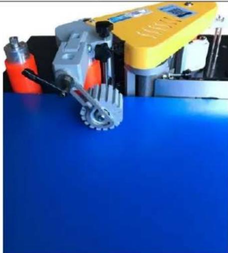
Industrial machine with yellow and gray components on a blue surface, no visible text or symbols4
This User Manual has been translated using machine translation. We have made every effort to ensure the translation is accurate, but please note that automated translations are not perfect and are not meant to replace human translators. The official version of the User Manual is in English. Any differences between the translated version and the original English are not legally binding. If you have any questions about the accuracy of the translation, please refer to the English version, which is the official reference. More language versions are available upon request via info@expondo.com.
Technical data
| Parameter description Parameter value | |
| Product name | Edge banding machine |
| Model | MSW-EDGE-1400TE |
| Rated voltage [V~] / frequency [Hz] | 230 / 50 |
| Rated power [W] | 850 |
| 800 x 1020 x 550 | |
| Weight [kg] | 33 |
1. General description
The user manual is designed to assist in the safe and trouble-free use of the device. The product is designed and manufactured in accordance with strict technical guidelines, using state-of-the-art technologies and components. Additionally, it is produced in compliance with the most stringent quality standards.
DO NOT USE THE DEVICE UNLESS YOU HAVE THOROUGHLY READ AND UNDERSTOOD THIS USER MANUAL.
To increase the product life of the device and to ensure trouble-free operation, use it in accordance with this user manual and regularly perform maintenance tasks. The technical data and specifications in this user manual are up to date. The manufacturer reserves the right to make changes associated with quality improvement. The device is designed to reduce noise emission risks to a minimum, taking into account technological progress and noise reduction opportunities.
Legend


The product satisfies the relevant safety standards.
Read instructions before use.
The product must be recycled.
WARNING! or CAUTION! or REMEMBER! Applicable to the given situation. (general warning sign)
Wear a dust mask (respiratory tract protection).
Use guard.
ATTENTION! Electric shock warning!
ATTENTION! Rotating parts, entanglement hazard!

WARNING! Toxic substances, danger of poisoning!
ATTENTION! Hand crush hazard!
Emergency stop!
ATTENTION! Hot surface, risk of burns!
Only use indoors.

PLEASE NOTE! Drawings in this manual are for illustration purposes only and in some details may differ from the actual product.
2. Usage safety

ATTENTION! Read all safety warnings and all instructions. Failure to follow the warnings and instructions may result in electric shock, fire and/or serious injury or even death.
The terms "device" or "product" are used in the warnings and instructions to refer to: Edge banding machine
2.1. Electrical safety
a) The plug must fit the socket. Do not modify the plug in any way. Using original plugs and matching sockets reduces the risk of electric shock.
b) Avoid touching earthed elements such as pipes, heaters, boilers and refrigerators. There is an increased risk of electric shock if the earthed device is exposed to rain, comes into direct contact with a wet surface or is operating in a damp environment. Water getting into the device increases the risk of damage to the device and of electric shock.
c) Do not touch the device with wet or damp hands.
d) Use the cable only for its designated use. Never use it to carry the device or to pull the plug out of a socket. Keep the cable away from heat sources, oil, sharp edges or moving parts. Damaged or tangled cables increase the risk of electric shock.
e) Do not use the device if the power cord is damaged or shows obvious signs of wear. A damaged power cord should be replaced by a qualified electrician or the manufacturer's service centre.
f) To avoid electric shock, do not immerse the cord, plug or device in water or other liquids. Do not use the device on wet surfaces.
g) ATTENTION! DANGER TO LIFE! While cleaning, never immerse the device in water or other liquids.
h) Do not use in very humid environments or in the direct vicinity of water tanks.
i) Before the first use, please check whether the main voltage type and current comply with the indicated data on the type plate.
2.2. Safety in the workplace
a) Make sure the workplace is clean and well lit. A messy or poorly lit workplace may lead to accidents. Try to think ahead, observe what is going on and use common sense when working with the device.
b) If you discover damage or irregular operation, immediately switch the device off and report it to a supervisor without delay.
c) If there are any doubts as to the correct operation of the device, contact the manufacturer's support service.
d) Only the manufacturer's service point may repair the device. Do not attempt any repairs independently!
e) In case of fire, use a powder or carbon dioxide (CO2) fire extinguisher (one intended for use on live electrical devices) to put it out.
f) Children or unauthorised persons are forbidden to enter a work station. A distraction may result in loss of control over the device.
g) Use the device in a well-ventilated space.
h) The device produces dust and debris during operation. It is important to protect bystanders from their harmful effects.
i) Use the "EMERGENCY STOP" if there is a risk of injury or death, accident or damage.
j) Regularly inspect the condition of the safety labels. If the labels are illegible, they must be replaced.
k) Please keep this manual available for future reference. If this device is passed on to a third party, the manual must be passed on with it.
I) Keep packaging elements and small assembly parts in a place not available to children.
m) Keep the device away from children and animals.
n) If this device is used together with another equipment, the remaining instructions for use shall also be followed.

Remember! When using the device, protect children and other bystanders.
2.3. Personal safety
a) Do not use the device when tired, ill or under the influence of alcohol, narcotics or medication which can significantly impair the ability to operate the device.
b) The machine may be operated by physically fit persons who are able to handle the machine, are properly trained, who have reviewed this operating manual and have received training in occupational health and safety.
c) When working with the device, use common sense and stay alert. Temporary loss of concentration while using the device may lead to serious injuries.
d) Use personal protective equipment as required for working with the device, specified in section 1 "Legend". The use of correct and approved personal protective equipment reduces the risk of injury.
e) To prevent the device from accidentally switching on, make sure the switch is on the OFF position before connecting to a power source.
f) Do not overestimate your abilities. When using the device, keep your balance and remain stable at all times. This will ensure better control over the device in unexpected situations.
g) Do not wear loose clothing or jewellery. Keep hair, clothes and gloves away from moving parts. Loose clothing, jewellery or long hair may get caught in moving parts.
h) Remove all adjusting tools or spanners before turning the device on. A tool or spanner left in the revolving part of the device may cause injury.
i) The device is not a toy. Children must be supervised to ensure that they do not play with the device.
j) If suction is to be connected to the device, check all connections and make sure they are tight. Using a dedusting system may reduce the risks associated with dust.
2.4. Safe device use
a) Do not overload the device. Use the appropriate tools for the given task. A correctly-selected device will perform the task for which it was designed better and in a safer manner.
b) Do not use the device if the "ON/OFF" switch does not function properly (does not switch the device on and off). Devices which cannot be switched on and off using the ON/OFF switch are hazardous, should not be operated and must be repaired.
c) Make sure the plug is disconnected from the socket before attempting any adjustments, accessory replacements or before putting the device aside. Such precautions will reduce the risk of accidentally activating the device.
d) When not in use, store in a safe place, away from children and people not familiar with the device who have not read the user manual. The device may pose a hazard in the hands of inexperienced users.
e) Keep the device in perfect technical condition. Before each use check for general damage, especially check moving components for cracked parts or elements, and for any other conditions which may impact the safe operation of the device. If damage is discovered, hand over the device for repair before use.
f) Keep the device out of the reach of children.
g) To ensure the operational integrity of the device, do not remove factory-fitted guards and do not loosen any screws.
h) When transporting and handling the device between the warehouse and the destination, observe the occupational health and safety principles for manual transport operations which apply in the country where the device will be used.
i) Avoid situations where the device stops working during use due to excessive loading. This may result in overheating of the drive elements and damage to the device.
j) Do not touch articulated parts or accessories unless the device has been disconnected from the power source.
k) Do not move, adjust or rotate the device in the course of work.
I) Do not leave this appliance unattended while it is in use.
m) Clean the device regularly to prevent stubborn grime from accumulating.
n) Do not work on two workpieces at the same time.
o) It is forbidden to interfere with the structure of the device in order to change its parameters or construction.
p) Keep the device away from sources of fire and heat.
q) Do not cover the ventilation openings!
r) NOTE: During operation, some elements of the device become very hot – scalding hazard!
s) Use protective glasses. When working in a dusty environment, additionally wear a dust mask.
t) Keep handles dry, clean and free of oil or grease.

ATTENTION! Despite the safe design of the device and its protective features, and despite the use of additional elements protecting the operator, there is still a slight risk of accident or injury when using the device. Stay alert and use common sense when using the device.
3. Use guidelines
Edge banding machine is designed to glue furniture edges with veneer, PVC or ABS materials.
The user is liable for any damage resulting from unintended use of the device.
3.1. Device description
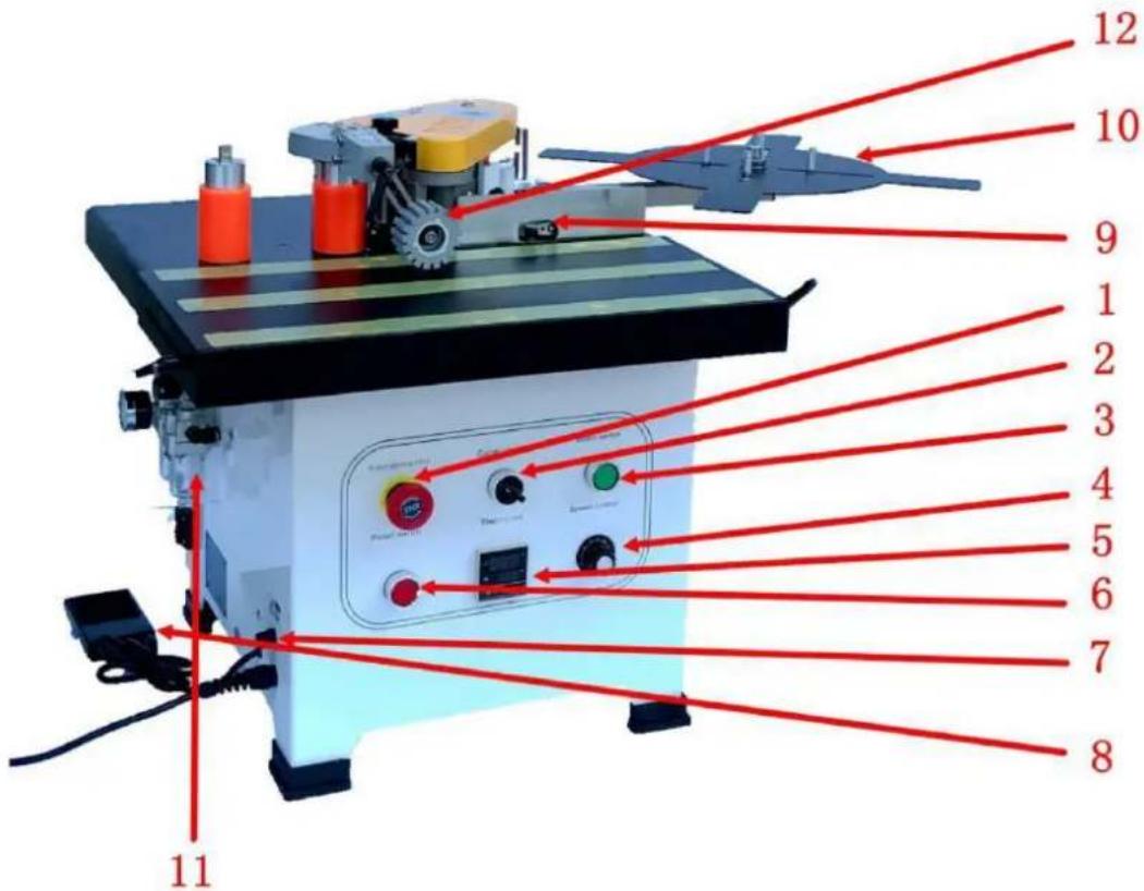
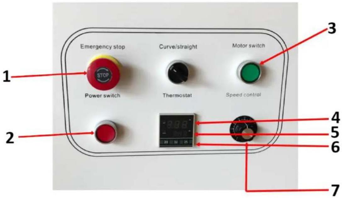
| 1 Emergency stop switch | Emergency stop machine button |
| 2 Selected switch | Curved (irregular), straight edge conversion |
| 3 Motor switch | Control motor start and stop |
| 4 Speed control knob | Adjust the working speed of edge banding |
| 5 Thermostat | Temperature control adjustment |
| 6 Power switch | Control the machine power |
| 7 Fuse | Protect circuits from overload or short circuit |
| 8 Foot pedal control | For curved (irregular) edge banding conveyor edge |
| 9 Limit switch | For straight edge conveyor edge |
| 10 Feeding plate | Supporting edge tape |
| 11 Air filter | Gas filtration and gas pressure regulation |
| 12 Platen wheel | Auxiliary sheet pressure panel |
3.2. Preparing for use
APPLIANCE LOCATION
The temperature of environment must not be higher than 40^ C and the relative humidity should be less than 85%. Ensure good ventilation in the room in which the device is being used. There should be at least 10 cm distance between each side of the device and the wall or other objects. The device should always be used when positioned on an even, stable, clean, fireproof and dry surface, and be out of the reach of children and persons with limited mental and sensory functions. Position the device such that you always have access to the power plug. The power cord connected to the appliance must be properly grounded and correspond to the technical details on the product label.
3.3. Device use
Safety advice:
- Please read this manual before use, especially the safety instructions. You must comply with all safety guidelines. Our EDGE BANDER is manufactured using technology recognized as the most effective and safest on the market. However, it may still pose a potential danger if not used correctly. The edge bander should only be operated under the following conditions:
- It must be used by professional personnel or under supervision.
○ Operate in a safe and clean working environment. Ensure the power supply has proper grounding protection.
If the machine malfunctions, immediately turn off the power and unplug it before opening the protective cover. Do not power it on again until the issue is resolved.
- The device is a double-sided edge-banding machine. It is suitable for working on various materials, such as high-density plates, particle boards, multi-layer solid wood boards, and artificial boards.
- Improper operation can cause harm to the user or damage the edge bander.
-
The warranty does not apply in the following situations:
-
If the machine is used in an inappropriate environment (e.g., wet or dirty conditions).
■ If the machine is assembled, operated, or maintained incorrectly.
■ If the machine is operated in the presence of safety defects.
■ If unauthorized modifications or repairs are made to the edge bander.
■ If consumable parts are replaced without authorization.
■ In the event of force majeure or accidents.
Security notification:
• Store this manual with the edge bander.
- Comply with local operational and electrical safety regulations.
- Ensure the safety marks on the edge bander are clearly visible. Replace them immediately if damaged.
Electrical maintenance:
- The circuit must be installed, checked, and maintained by a qualified electrician.
• Regularly inspect the electrical components of the edge-banding machine to prevent loosening. - Verify that the input voltage is correct. The local voltage should not exceed ± 10% .
Machine maintenance and cleaning:
- Perform regular cleaning and maintenance within the recommended intervals. Always disconnect the plug from the power source during cleaning.
o Lubricate the transmission parts, such as the chain and gear, each month.
- Clean hot melt glue and dust from the edge bander at the end of each working day.
Operating guidelines and precautions:
- Turn on the power switch once energized. The thermostat will automatically start warming up through a self-inspection program.
- Do not place the machine in wet areas. Ensure there is adequate lighting during operation.
- Keep children away from the edge bander.
- Do not wear scarves, loose sleeves, necklaces, or any loose clothing that could be caught in the edge bander.
- Ensure that the switch is in the "Stop - OFF" position before powering on.
-
Be cautious: The melting pot may reach temperatures of up to 200^ C. Do not touch the heated area around the melting pot.
-
When using the edge bander, it is recommended to hold the machine with both hands during operation.
- Before operating, check that the wire length is sufficient and free from obstructions.
- Do not touch combustible or explosive materials.
- Avoid using the machine in high-moisture areas, and never operate it outdoors in the rain.
- Harmful gases may be produced during use. Operate the machine in a well-ventilated area or wear an activated carbon mask.
Post-operation and maintenance:
- Keep this manual for reference, particularly for spare parts and maintenance.
- After completing work, switch off both the heating and power switches. Allow the machine to cool down completely before storing it in the tool box.
- Clean any overflowed hot melt glue left on the machine at all times.
- After adding hot melt glue, immediately cover the melting pot to prevent debris such as sawdust from falling in.
If there is foreign matter in the glue pot, the hot melt glue inside will need to be replaced. Cool down the edge bander for two minutes or heat it up to 80°C. Use tools to remove the foreign object before the glue melts fully. Let the remaining hot melt glue flow back into the pot for cleaning.
- When using hot melt glue at a different melting temperature, remove the old glue from the melting pot and the glue shaft before adding new glue.
Preparation before operating the system:
- Keep the machine clean at all times.
• Store wood and other materials at room temperature.
• High humidity in the processed material can negatively affect adhesion quality. - When edge banding, apply appropriate pressure to the workpiece. Insufficient pressure can lead to poor banding quality.
• Store hot melt glue in a cool, dry place. - Do not forcefully open the melting pot cover or adjust the glue knob when the hot melt glue has cooled, as this could damage the machine.
- Before starting edge banding, ensure the hot melt glue in the melting pot has melted properly.
• The diameter of the inner arc should not be less than 40mm. - Use low-temperature hot melt glue (120–180°C) as recommended by our company. Do not exceed a maximum temperature of 200°C.
1 Emergency stop
2 Power switch
3 Motor switch*
4 Current Temperature
5 Preset temperature
6 Up and down button
7 Speed control knob
*The motor switch lamp is on when the temperature reaches the set temperature
Operating instructions:
- After the power switch is turned on, the temperature controller will display the current temperature (in red). Adjust the temperature (in green) via the thermostat panel. The internal relay is then activated, and the light will turn on. The thermostat has a power-off memory function, so the temperature does not need to be reset after disconnecting the power supply.
Indicator lights and machine operations:
• Temperature control indicator: The light turns on when heating begins.
- Operation indicator: When the temperature reaches the set level, the motor switch light will turn on, and the motor can be activated to accelerate the melting of the glue.
- Once the motor switch lamp is on, adjust the speed using the adjustment knob and start the sealing process.
- The curve/straight switch must be closed by the motor switch for the machine to operate.
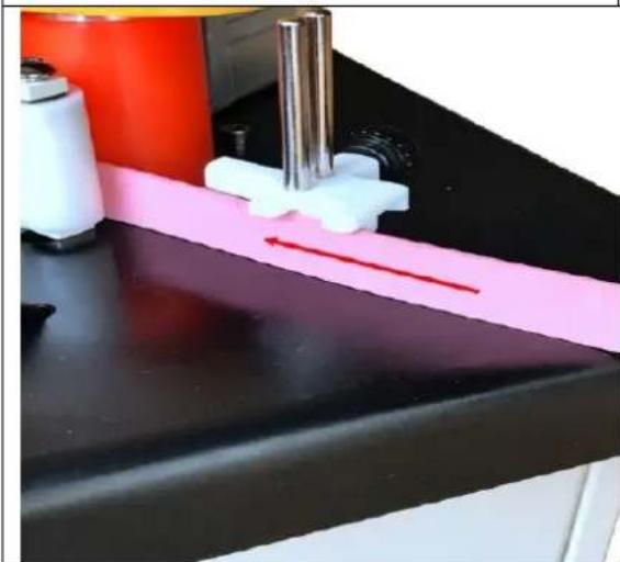
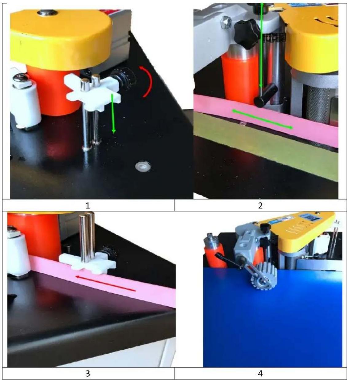
Strake height adjustment:
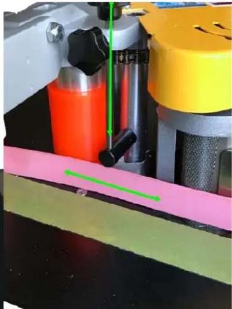
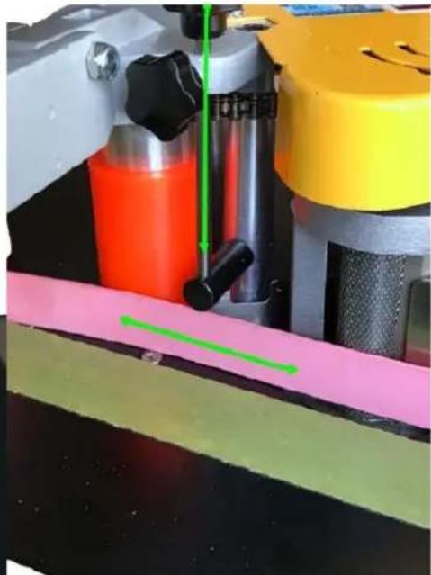
- Loosen the knob of the front height-limiting device (see picture 1).
- Set the edge to the high limit for measuring pressure. Ensure the high wing is exposed to the edge, and then lock the knob (see pictures 2 and 3).
- Based on the height of the workpiece, place the workpiece under the platen roller. Press the platen wheel down so that the workpiece is pressed against the main surface of the machine, leaving proper
spacing. Lock the adjustable handle. After adjustment, release the adjustable handle (see figure 4), and once the adjustment is complete, lock the handle again.
Adjust the amount of glue:
- When the temperature of the edge banding machine reaches the working temperature, cut a piece of edge (about 20 cm) for testing. Adjust the glue volume knob to the appropriate amount, ensuring that the glue is evenly coated on the edge band.
Note: When the hot melt has cooled, some of the structure may stick, preventing the adjustment knob from turning.
Banding tape thickness adjustment:
- If the edge is too thin or too soft, adjust the thickness using the adjusting knob and fixing screw to ensure proper edge banding.
Operation:
- When applying banding tape to the workpiece, apply appropriate pressure to enhance the banding effect.
- After confirming that there is no residue in the edge banding machine, turn on the starter switch. Once the temperature of the hot melt adhesive cylinder reaches the set temperature, the indicator light on the motor switch button will turn on. Press the button to accelerate the melting cycle.
- Depending on the type of hot melt adhesive, it may take time for the glue to melt completely. The processing board should be laid flat on the panel, and the wood board pressed against the limit switch on the stopper.
- Place the processing board near the gluing shaft, with the starting point of the gluing at about 5 cm. The board will press down on the edge switch, which in turn activates the pulley. The cylinder is pressed against the feeding pulley, driving the sealing strip to the shaft.
- When the sealing strip reaches the driving wheel through the gluing shaft, the processed material will be pressurized with moderate force and pressed against the driving wheel for edge banding.
3.4. Cleaning and maintenance
a) Unplug the mains plug and allow the device to cool completely before each cleaning, adjustment or replacement of accessories, or if the device is not being used.
• Wait for the rotating elements to stop.
b) Use only non-corrosive cleaners to clean the surface.
c) After cleaning the device, all parts should be dried completely before using it again.
d) Store the unit in a dry, cool place, free from moisture and direct exposure to sunlight.
e) Do not spray the device with a water jet or submerge it in water.
f) Do not allow water to get inside the device through vents in the housing of the device.
g) Clean the vents with a brush and compressed air.
h) The device must be regularly inspected to check its technical efficiency and spot any damage.
i) Use a soft, damp cloth for cleaning.
j) Do not use sharp and/or metal objects for cleaning (e.g. a wire brush or a metal spatula) because they may damage the surface material of the appliance.
k) Do not clean the device with an acidic substance, agents of medical purposes, thinners, fuel, oils or other chemical substances because it may damage the device.
DISPOSING OF USED DEVICES:
Do not dispose of this device in municipal waste systems. Hand it over to an electric and electrical device recycling and collection point. Check the symbol on the product, instruction manual and packaging. The plastics used to construct the device can be recycled in accordance with their markings. By choosing to recycle you are making a significant contribution to the protection of our environment.
Contact local authorities for information on your local recycling facility.
3.5 Troubleshooting
| Problem | Cause | Solution |
| Machine cannot start | Fuse burn | Replace fuse |
| Glue uneven on the banding tape | 1. Incomplete melting of hot melt glue | Open the melting pot cover to check the hot melt glue |
| 2. Insufficient glue | Adjust gluing knob | |
| 3. The bending stripe deformed | Replace with better edge banding tape | |
| 4. Hot melt glue has not yet been supplied to the glue wheel | Wait a few seconds for hot melt re-flow to melting pot | |
| Poor adhesion of the banding tape | 1. Non-parallel adhesive veneer | Re-calibrate the support plate (refer to the page) |
| 2. Hot melt glue deteriorated from long heating | Replace the hot melt glue | |
| 3. Hot melt glue temperature is incorrect | Know the correct working temperature for the hot melt glue and adjust the machine accordingly | |
| Banding tape is not level | Twist strake attached at the starting point, or pushing slower than the speed | Ensure the support plate is flush with the workpiece and pressing properly. Fit the edge tightly to the workpiece without loosening |
| Banding tape is not moving | Wheel or feed wheel skid | Clean the belt pulley and feed wheel |
| Electric start abnormal | Hot melt glue not yet dissolved | Need to re-adjust the temperature, then start running |
| Indicator normal, but motor does not turn | Motor switch damaged | Replace the motor switch, check wiring |
| Abnormal heating | Abnormal heating detection | Contact a professional technician to check for temperature drops or short circuits |

natural_image
Close-up of two mechanical testing setups showing a yellow and pink assembly with red arrows indicating motion or movement (no text or symbols visible)1
natural_image
Close-up of a mechanical testing setup with colored components and a green measurement line (no visible text or symbols)2

natural_image
Close-up of a lab bench with a pink strip and white tool, no visible text or symbols3

natural_image
Industrial machine with yellow and red components on a blue surface, no visible text or symbols4
natural_image
Two views of a mechanical testing setup with yellow and pink components, showing motion indicators (no text or symbols visible)1
natural_image
Close-up of a mechanical testing setup with colored components and a green measurement line (no visible text or symbols)2

natural_image
Close-up of a pink strip on a black surface with white and red components, no visible text or symbols3
natural_image
Industrial machine with yellow and gray components on a blue surface, no visible text or symbols4
OBS! Giftige stoffer, fare for forgiftning!
APPARATETS PLACERING
VAROITUS! Myrkyllisiä aineita, myrkytysvaara!
HUOMIO! Käsien puristumisvaara!
Hätäpysäytys!
HUOMIO! Kuuma pinta, palovammavaara!
PLAATS VAN HET APPARAAT
ADVARSEL! Giftige stoffer, fare for forgiftning!
OBS! Varm overflate, fare for forbrenning!
| 1 Nødstoppbryter | Nødstopp maskinknapp |
| 2 Valgt bryter | Buet (uregelmessig), rett kantkonvertering |
| 3 Motorbryter | Kontroller motorstart og stopp |
| 4 hastighetskontrollknapp | Juster arbeidshastigheten for kantbånd |
| 5 Termostat | Justering av temperaturkontroll |
| 6 Strømbryter | Kontroller maskinens kraft |
| 7 Sikring | Beskytt kretser mot overbelastning eller kortslutning |
| 8 Fotpedalkontroll | For buet (uregelmessig) kantbåndtransportørkant |
| 9 Grensebryter | For rettkanttransportørkant |
| 10 Føringsplate | Støttekanttape |
| 11 Luftfilter | Gassfiltrering og gasstrykkregulering |
| 12 Platehjul | Ekstra arktrykkpanel |