WOBD-1500Y - Industrial milling machine MSW - Free user manual and instructions
Find the device manual for free WOBD-1500Y MSW in PDF.

User questions about WOBD-1500Y MSW
0 question about this device. Answer the ones you know or ask your own.
Ask a new question about this device
Download the instructions for your Industrial milling machine in PDF format for free! Find your manual WOBD-1500Y - MSW and take your electronic device back in hand. On this page are published all the documents necessary for the use of your device. WOBD-1500Y by MSW.
USER MANUAL WOBD-1500Y MSW
TABLE MILLING MACHINE
| DE | Produktname | TISCHFRÄSMASCHINE |
| EN | Product name | TABLE MILLING MACHINE |
| PL | Nazwa produktu | FREZARKA STOŁOWA |
| CZ | Název výrobku | STOLOVÁ FRÉZKA |
| FR | Nom du produit | FRAISEUSE DE TABLE |
| IT | Nome del prodotto | FRESA DA TAVOLO |
| ES | Nombre del producto | FRESADORA DE MESA |
| HU | Termék neve | ASZTALI MARÓGÉP |
| DA | Produktnavn | BORDFRÆSEMASKINE |
| FI | Tuotteen nimi | PÖYTÄJYRSIN |
| NL | Productnaam | TAFELFREESMACHINE |
| NO | Produktnavn | BORDFRES |
| SE | Produktnamn | BORDFRÄS |
| PT | Nome do produto | FRESADORA DE MESA |
| SK | Názov produktu | STOLOVÁ FRÉZKA |
| DE | Modell | MSW-WOBD-1500Y |
| EN | Product model | |
| PL | Model produktu | |
| CZ | Model výrobku | |
| FR | Modèle | |
| IT | Modello | |
| ES | Modelo | |
| HU | Modell | |
| DA | Model | |
| FI | Tuotteen malli | |
| NL | Productmodel | |
| NO | Produktmodell | |
| SE | Produktmodell | |
| PT | Modelo do produto | |
| SK | Model | |
| DE | Hersteller | expondo Polska sp. z o.o. sp. k. |
| EN | Manufacturer | |
| PL | Producent | |
| CZ | Výrobce | |
| FR | Fabricant | |
| IT | Produttore | |
| ES | Fabricante | |
| HU | Termelő | |
| DA | Producent | |
| FI | Valmistaja | |
| NL | Producent | |
| NO | Produsent | |
| SE | Tillverkare | |
| PT | Fabricante | |
| SK | Výrobca | |
| DE | Anschrift des Herstellers | ul. Nowy Kisielin – Innowacyjna 7, 66-002 Zielona Góra | Poland, EU |
| EN | Manufacturer Address | |
| PL | Adres producenta | |
| CZ | Adresa výrobce | |
| FR | Adresse du fabricant | |
| IT | Indirizzo del produttore | |
| ES | Dirección del fabricante | |
| HU | A gyártó címe | |
| DA | Producentens adresse | |
| FI | Valmistajan osoite | |
| NL | Adres producent | |
| NO | Produsentens adresse | |
| SE | Tillverkarens adress | |
| PT | Endereço do fabricante | |
| SK | Adresa výrobcu |

natural_image
Black metal mechanical component with multiple ports and mounting holes (no visible text or symbols)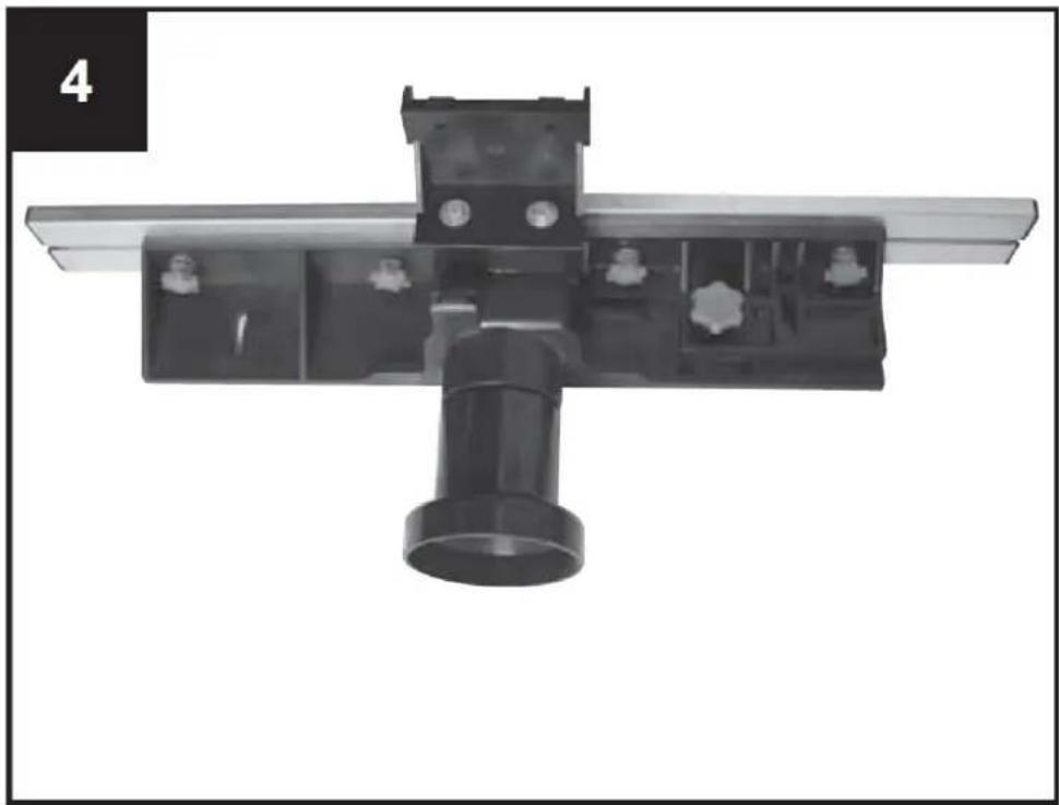
natural_image
Mechanical assembly component with a central cylindrical shaft and mounting bracket (no visible text or symbols)
natural_image
Close-up of a mechanical assembly with a black plastic frame and mounting bracket (no visible text or symbols)natural_image
Close-up of a mechanical assembly with multiple bolt holes and a black plastic component (no visible text or symbols)
natural_image
Close-up of a hand pressing a small metallic bolt onto a dark surface, no visible text or symbols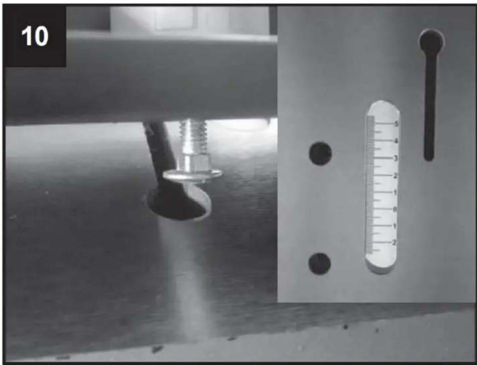
natural_image
Experimental setup with a mechanical component and a thermometer, no visible text or symbols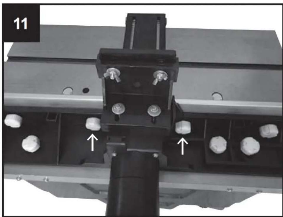
natural_image
Mechanical assembly with metallic components and white cylindrical features, no visible text or symbolsnatural_image
Close-up of a hand holding a metal bracket on a metal workbench, with no visible text or symbols.
natural_image
Industrial machine component with two metallic parts and a central black frame, no visible text or symbolsnatural_image
Close-up of a hand adjusting a mechanical component with a circular dial and a ruler for scale (no visible text or symbols)
natural_image
Close-up of a hand turning a mechanical component with a wrench, no visible text or symbols
natural_image
Top-down view of an orange industrial control panel with a red indicator light and a small red device (no text or symbols visible)

| 20 | ∅ [mm] | ||||||
| ≤40 | 8 | 19 | 29 | 35 | 38 | 39 | |
| ≤60 | 15 | 26 | 36 | 40 | 49 | 59 | |
| ≤80 | 21 | 32 | 42 | 50 | 60 | 69 | |
 [min-1] [min-1] | 11500 | 13000 | 16000 | 18500 | 21000 | 24000 | |
natural_image
Mechanical assembly with metal components and a numbered label (20 and 5), no readable text or symbols beyond labels
This User Manual has been translated for your convenience using machine translation. Reasonable efforts have been made to provide an accurate translation; however, no automated translation is perfect nor is it intended to replace human translators. The official User Manual is the English version. Any discrepancies or differences created in the translation are not binding and have no legal effect for compliance or enforcement purposes. If any questions arise related to the accuracy of the information contained in the User Manual, please refer to the English version of those contents which is the official version.
Technical data
| Parameter description | Parameter value |
| Product name | Table milling machine |
| Model | MSW-WOBD-1500Y |
| Rated voltage [V~] / frequency [Hz] | 230 / 50 |
| Rated power [W] | 1500 |
| Rated speed [rpm] | 11500-24000 |
| Spindle [mm] | 0-40 |
| Table dimensions [mm] | 610 x 360 |
| Dimensions (width x depth x height) [mm] | 1030 x 360 x 310 |
| Weight [kg] | 20.6 |
1. General description
The user manual is designed to assist in the safe and trouble-free use of the device. The product is designed and manufactured in accordance with strict technical guidelines, using state-of-the-art technologies and components. Additionally, it is produced in compliance with the most stringent quality standards.
DO NOT USE THE DEVICE UNLESS YOU HAVE THOROUGHLY READ AND UNDERSTOOD THIS USER MANUAL.
To increase the product life of the device and to ensure trouble-free operation, use it in accordance with this user manual and regularly perform maintenance tasks. The technical data and specifications in this user manual are up to date. The manufacturer reserves the right to make changes associated with quality improvement. The device is designed to reduce noise emission risks to a minimum, taking into account technological progress and noise reduction opportunities.
Legend

The product satisfies the relevant safety standards.

Read instructions before use.
The product must be recycled.

WARNING! or CAUTION! or REMEMBER! Applicable to the given situation. (general warning sign)
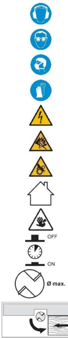
Use ear protection. Exposure to loud noise may result in hearing loss.
Wear protective goggles.
Wear a dust mask (respiratory tract protection).
Wear protective gloves.
ATTENTION! Electric shock warning!
ATTENTION! Loud noise warning!
ATTENTION! Rotating parts, entanglement hazard!
Only use indoors.
ATTENTION! Sharp, moving machine parts! Danger of cutting or amputating fingers/ limbs.
Overload switch
Max. cutter block diameter
Observe the insertion direction!
flowchart
graph TD
    A["Start"] --> B{Decision}
    B -->|Yes| C["Process Step"]
    B -->|No| D["End"]

PLEASE NOTE! Drawings in this manual are for illustration purposes only and in some details may differ from the actual product.
2. Usage safety

ATTENTION!
Read all safety warnings and all instructions. Failure to follow the warnings and instructions may result in electric shock, fire and/or serious injury or even death.
The terms "device" or "product" are used in the warnings and instructions to refer to:
Table milling machine
2.1. Electrical safety
a) The plug must fit the socket. Do not modify the plug in any way. Using original plugs and matching sockets reduces the risk of electric shock.
b) Avoid touching earthed elements such as pipes, heaters, boilers and refrigerators. There is an increased risk of electric shock if the earthed device is exposed to rain, comes into direct contact with a wet surface or is operating in a damp environment. Water getting into the device increases the risk of damage to the device and of electric shock.
c) Do not touch the device with wet or damp hands.
d) Use the cable only for its designated use. Never use it to carry the device or to pull the plug out of a socket. Keep the cable away from heat sources, oil, sharp edges or moving parts. Damaged or tangled cables increase the risk of electric shock.
e) Do not use the device if the power cord is damaged or shows obvious signs of wear. A damaged power cord should be replaced by a qualified electrician or the manufacturer's service centre.
f) To avoid electric shock, do not immerse the cord, plug or device in water or other liquids. Do not use the device on wet surfaces.
g) Do not use in very humid environments or in the direct vicinity of water tanks.
h) Prevent the device from getting wet. Risk of electric shock!
i) Before the first use, please check whether the main voltage type and current comply with the indicated data on the type plate.
2.2. Safety in the workplace
a) Make sure the workplace is clean and well lit. A messy or poorly lit workplace may lead to accidents. Try to think ahead, observe what is going on and use common sense when working with the device.
b) Do not use the device in a potentially explosive environment, for example in the presence of flammable liquids, gases or dust. The device generates sparks which may ignite dust or fumes.
c) If you discover damage or irregular operation, immediately switch the device off and report it to a supervisor without delay.
d) If there are any doubts as to the correct operation of the device, contact the manufacturer's support service.
e) Only the manufacturer's service point may repair the device. Do not attempt any repairs independently!
f) In case of fire, use a powder or carbon dioxide (CO2) fire extinguisher (one intended for use on live electrical devices) to put it out.
g) Children or unauthorised persons are forbidden to enter a work station. A distraction may result in loss of control over the device.
h) Use the device in a well-ventilated space.
i) The device produces dust and debris during operation. It is important to protect bystanders from their harmful effects.
j) Regularly inspect the condition of the safety labels. If the labels are illegible, they must be replaced.
k) Please keep this manual available for future reference. If this device is passed on to a third party, the manual must be passed on with it.
I) Keep packaging elements and small assembly parts in a place not available to children.
m) Keep the device away from children and animals.
n) If this device is used together with another equipment, the remaining instructions for use shall also be followed.

Remember! When using the device, protect children and other bystanders.
2.3. Personal safety
a) Do not use the device when tired, ill or under the influence of alcohol, narcotics or medication which can significantly impair the ability to operate the device.
b) The machine may be operated by physically fit persons who are able to handle the machine, are properly trained, who have reviewed this operating manual and have received training in occupational health and safety.
c) The machine is not designed to be handled by persons (including children) with limited mental and sensory functions or persons lacking relevant experience and/or knowledge unless they are supervised by a person responsible for their safety or they have received instruction on how to operate the machine.
d) When working with the device, use common sense and stay alert. Temporary loss of concentration while using the device may lead to serious injuries.
e) Use personal protective equipment as required for working with the device, specified in section 1 "Legend". The use of correct and approved personal protective equipment reduces the risk of injury.
f) To prevent the device from accidentally switching on, make sure the switch is on the OFF position before connecting to a power source.
g) Do not overestimate your abilities. When using the device, keep your balance and remain stable at all times. This will ensure better control over the device in unexpected situations.
h) Do not wear loose clothing or jewellery. Keep hair, clothes and gloves away from moving parts. Loose clothing, jewellery or long hair may get caught in moving parts.
i) If suction is to be connected to the device, check all connections and make sure they are tight. Using a dedusting system may reduce the risks associated with dust.
j) Remove all adjusting tools or spanners before turning the device on. A tool or spanner left in the revolving part of the device may cause injury.
k) Use eye, ear and respiratory protection.
I) The device is not a toy. Children must be supervised to ensure that they do not play with the device.
m) Do not put your hands or other items inside the device while it is in use!
2.4. Safe device use
a) Do not overload the device. Use the appropriate tools for the given task. A correctly-selected device will perform the task for which it was designed better and in a safer manner.
b) Do not use the device if the "ON/OFF" switch does not function properly (does not switch the device on and off). Devices which cannot be switched on and off using the ON/OFF switch are hazardous, should not be operated and must be repaired.
c) Disconnect the device from the power supply before commencement of adjustment, cleaning and maintenance. Such a preventive measure reduces the risk of accidental activation.
d) When not in use, store in a safe place, away from children and people not familiar with the device who have not read the user manual. The device may pose a hazard in the hands of inexperienced users.
e) Keep the device in perfect technical condition. Before each use check for general damage, especially check moving components for cracked parts or elements, and for any other conditions which may impact the safe operation of the device. If damage is discovered, hand over the device for repair before use.
f) Keep the device out of the reach of children.
g) Device repair or maintenance should be carried out by qualified persons, only using original spare parts. This will ensure safe use.
h) To ensure the operational integrity of the device, do not remove factory-fitted guards and do not loosen any screws.
i) When transporting and handling the device between the warehouse and the destination, observe the occupational health and safety principles for manual transport operations which apply in the country where the device will be used.
j) Avoid situations where the device stops working during use due to excessive loading. This may result in overheating of the drive elements and damage to the device.
k) Do not touch articulated parts or accessories unless the device has been disconnected from the power source.
I) Do not move, adjust or rotate the device in the course of work.
m) Do not leave this appliance unattended while it is in use.
n) Clean the device regularly to prevent stubborn grime from accumulating.
o) Do not work on two workpieces at the same time.
p) Do not touch any moving parts or accessories unless the device has been disconnected from the compressed air supply.
q) Do not cover the air intake and outlet.
r) The device is not a toy. Cleaning and maintenance may not be carried out by children without supervision by an adult person.
s) It is forbidden to interfere with the structure of the device in order to change its parameters or construction.
t) Keep the device away from sources of fire and heat.
u) Do not cover the ventilation openings!
v) NOTE: During operation, some elements of the device become very hot – scalding hazard!
w) Do not touch the moving cutting elements. Danger of cutting or amputating fingers/limbs

ATTENTION! Despite the safe design of the device and its protective features, and despite the use of additional elements protecting the operator, there is still a slight risk of accident or injury when using the device. Stay alert and use common sense when using the device.
3. Use guidelines
The router is ideal for machining wood and plastic and also for cutting out knots, cutting grooves, removing recesses, copying curves and logos, etc. The router must not be used for machining metal, stone, etc.
The equipment is to be used only for its prescribed purpose. Any other use is deemed to be a case of misuse. The user / operator and not the manufacturer will be liable for any damage or injuries of any kind caused as a result of this.
Please note that our equipment has not been designed for use in commercial, trade or industrial applications. Our warranty will be voided if the machine is used in commercial, trade or industrial businesses or for equivalent purposes.
Attention: The use of an accessory or an attachment not recommended in these operating instructions can lead to bodily injuries.
This product may be used only for the intended purpose. Any application not described in these operating instructions is regarded as inappropriate use. The operator, and not the manufacturer, is responsible for all damage or injuries as a result of inappropriate application.
- Support long work pieces correctly.
- Keep the table openings as small as possible regarding the size of the cutting tool by use of the correct table rings.
• Additional aids, like horizontal pressure means, are to be used for working on narrow work pieces. - Do not stand the machine in rain.
4. Package contents
- Open the packaging and remove the device carefully.
- Remove the packaging material as well as the packaging and transport bracing (if available).
- Check that the delivery is complete.
- Check the device and accessory parts for transport damage.
- If possible, store the packaging until the warranty period has expired.
ATTENTION!
The device and packaging materials are not toys! Children must not be allowed to play with plastic bags, film and small parts!
There is a risk of swallowing and suffocation!
- Plastic protective cover (1x)
- straight pin (1x)
- lock block (2x)
- bolt M6x35 (6x)
- locking knob, small (4x)
• big flat washer D6 (8x)
• T-type support assy (2x) - locking knob, Large (2x)
• U-type fastener assy (2x) - Long platen assy (1x)
- Small platen assy (1x)
- Long platen support pedestal (1x)
- hex bolt M6x45 (2x)
- big flat washer (4x)
- Nut M6 (2x)
- wing nut M6 (2x)
- bolt M6x35 (2x)
- dust port (1x)
- miter guage assy (1x)
• work table cover (1x)
- Extension table I (1x)
- Extension table II (1x)
- bolt M5x12 (6x)
- bolt M5X15 (8x)
- flat washer (14x)
- Slide block (2x)
- striker plate (2x)
• Large wrench (1x)
- Small wrench (1x)
- Hex wrench S=5 (1x)
- Hex wrench S=4 (1x)
- Hand wheel (1x)
- Cap nut M8 (1x)
- Chuck 1/2" (1x)
- Chuck 1/4" (1x)
- Long platen support pedestal (1x)
• Philips screw+flat washer+spring washer M5x12 (2x)
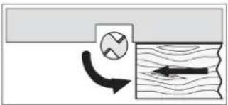
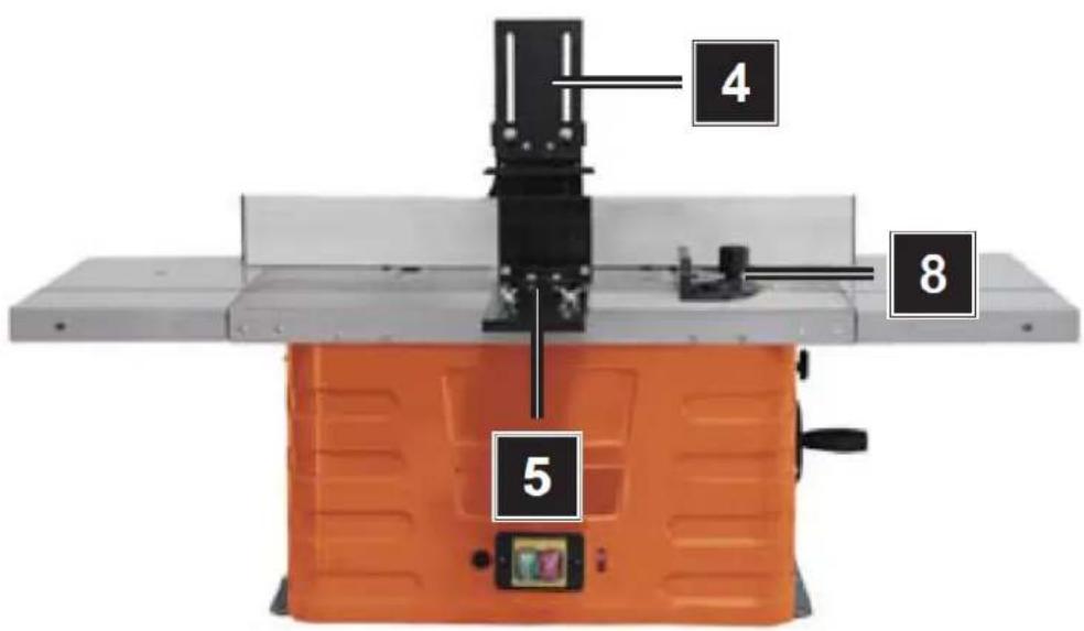
5. Device description
1 - Working table
2 - Milling notice
3 - Stop bar
4 - Upper pressure bar
5 - Lateral pressure bar
6 - Height adjustment
7 - Clamping screw
8 - Cross-cutting jig
9 - Speed adjustment
10 - Circuit breaker
11 - Right side table extension
12 - Left side table extension
13 - Overload switch
6. Assembly
Attention: Before doing any setting or maintenance work pull the power supply plug.
Fixing the machine
When using the machine it is recommended to fasten it to a work bench by means of the four holes
1) Holes must be drilled in the assembly surface, considering the spacing of the two fixing holes in the base.
2) Each leg must be tightened with bolts (not supplied).
3) The bolts must be sufficiently long: Take into account the thickness of the working surface onto which the machine has to be fastened.
4) Use the washers and screw the working surface on with the nuts.
5) The working surface must be sufficiently large in order to prevent tilting of the unit during working.
Attention: Before starting work, check the solidity of the working surface.
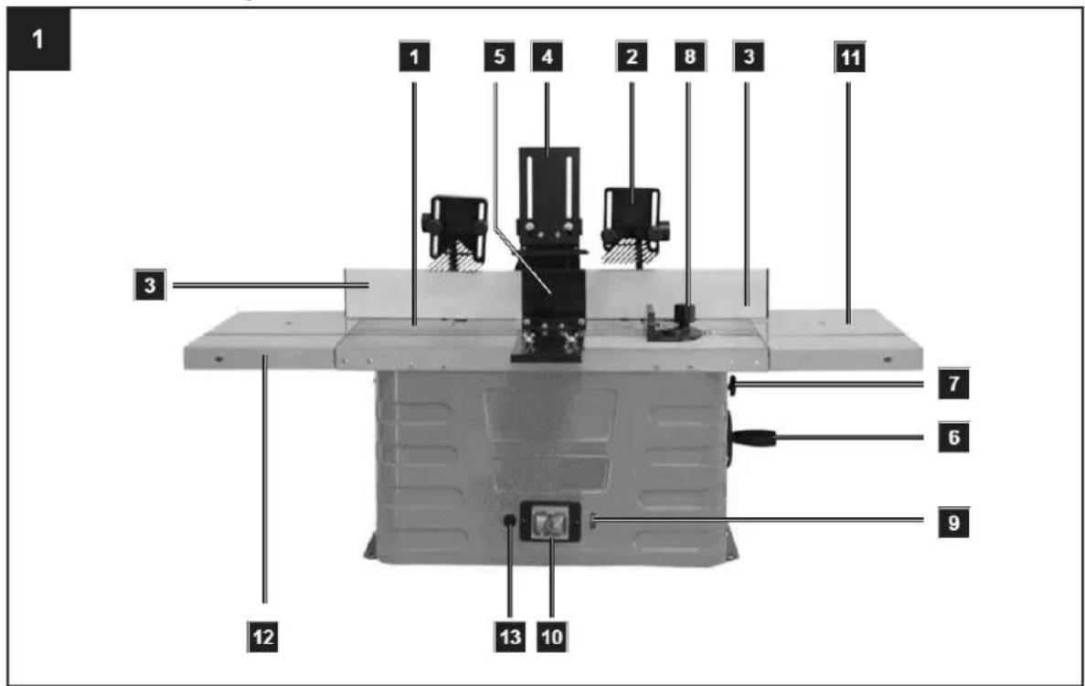
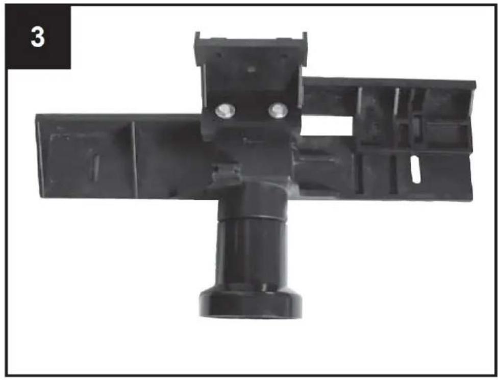
Moulding fence components:
A.1 - Base holder
A.2 - Bracket
B - Mounting bracket
C - Fence 2x
D - Pressure bar
E - Extraction connection piece
Attachment parts for moulding fence
5 Plastic cap nuts M6
5 Washers 6mm
5 Carriage bolts M6 x 25
Table attachment
1 Carriage bolt M6 x 20
1 Carriage bolt M6 x 40
2 Plastic cap nuts M6
2 Washers 6mm
Mounting the moulding fence, Fig. 2-5
The moulding fence has been shipped in the carton box disassembled. Before starting work, it must be assembled and fitted onto the working table.
Step 1: Assembly of part A and B
Push the mounting (B) onto the base holder (A. 1) in the groove provided (see Fig. 4). Now insert a carriage bolt M6 x 25 into the hole and screw on a plastic cap nut with a washer.
Step 2: Fitting the stop bars C
Insert two carriage bolts into the attachment holes and screw them on finger tight with a washer and a plastic cap nut. Then, with the groove, push the fence onto the carriage bolt caps. Now tighten both plastic cap nuts. Carry out the same process on the other side of the fence. Make sure you attach the fences (C) in the correct direction. Check that the fences (C) and the base holder and bracket (A. 1 + A. 2) are at the same height.
Step 3: Fitting pressure part D
Attach the pressure bar (D) to the fence with 2 carriage bolts, 2 washers and 2 plastic cap nuts.
natural_image
Mechanical component with black plastic housing and mounting bracket (no visible text or symbols)
natural_image
Mechanical assembly with a black cylindrical component mounted on a metal frame, no visible text or symbols
natural_image
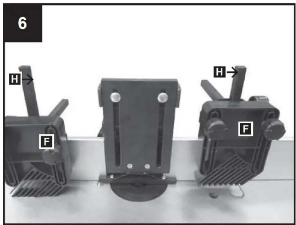
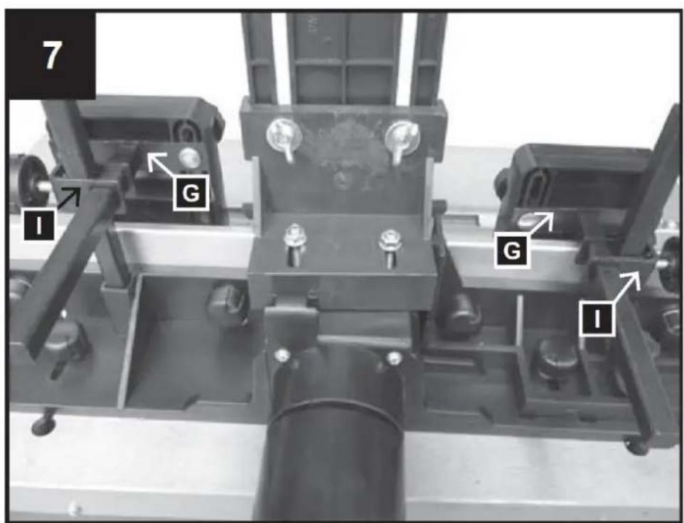
Close-up of a mechanical device with a black plastic housing and mounting bracket, mounted on a wooden surface (no visible text or symbols)Fixings for pressure device, Fig. 6.1 + 6.2
F - Pressure frame 2x
G - Square mounting plate 2x
H - Square bolt 2x
I - Clamp for square bolt 2x
Assembling the pressure device:
Insert the 2 square bolts (H) in the 2 square tubes provided and secure them with the 2 Allen screws. Attach the 2 clamps (I) on the 2 square bolts (H) using the 2 plastic cap screws. Then push the 2 square mounting plates (G) through the 2 openings of the 2 clamps (I). Finally, attach the pressure frames (F) to the square mounting plates using the 4 carriage bolts, the 4 washers and the 4 plastic nuts.
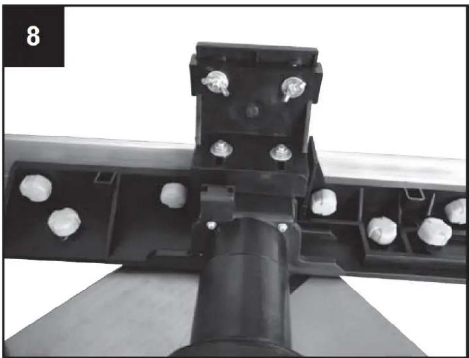
Fitting the moulding fence onto the working table, Fig. 8-11
The installation of the shaping stop collar is done as follows:
Fix the 2 plastic cap screws to the grooves in the moulding fence using the washers (Fig. 9).
Put the tops of the plastic cap screws through the opening in the table grooves (Fig. 10).
Position the moulding fence as required and tighten the plastic cap nuts (Fig. 11).
natural_image
Mechanical assembly with black plastic components and white spherical holes (no text or symbols visible)
natural_image
Close-up of a hand pressing a small metallic component on a dark surface, no visible text or symbols
natural_image
Experimental setup with a mechanical component and a thermometer, no visible text or symbols
natural_image
Mechanical assembly with metal components and white cylindrical elements, no visible text or symbolsKickback safety fence components
1 Kickback safety fence
1 Mounting bracket
Attachment parts for kickback safety fence
2 Recessed head screws M5 x 10
2 Washers 5mm
2 Circlips 5mm
2 Carriage bolts M6 x 25
2 Washers 6mm
2 Wing nuts M6
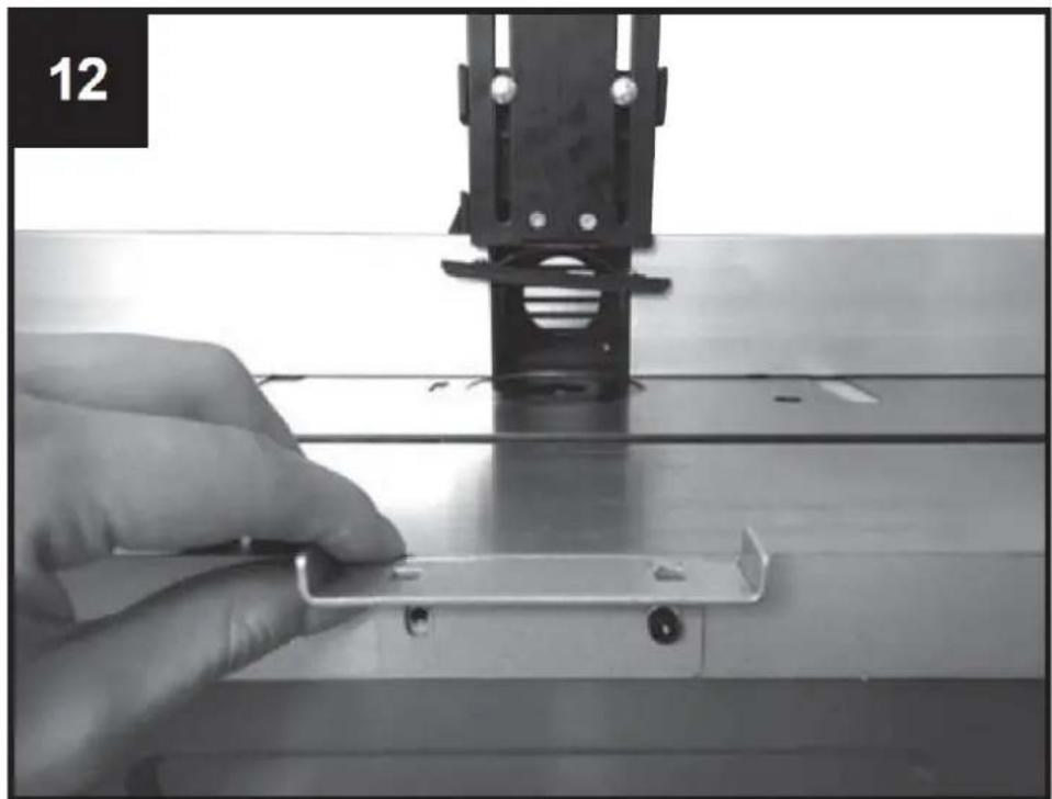
Fitting the return kick safety fence
- Locate the two holes at the centre of the machine front.
- Then align the mounting bracket to the two holes (Fig. 12).
- Insert the two bolts and their washers into the holes, then tighten them firmly with a four-way socket wrench.
• After that, install the fence in such a way that it can slide and be adjusted to the thickness of the work piece.
• After setting, fix it with the help of the two bolts (Fig. 13).
natural_image
Close-up of a hand holding a small metal bracket on a metal workbench, with no visible text or symbols.
natural_image
Industrial machine component with two metallic parts and a central black frame, no visible text or symbolsFitting the working depth
For setting or reducing the spindle height, turn the handle (serves for height-adjustment of the cutting knives) in order to reduce or increase the height, as required.
Secure the setting by tightening the clamping screw (7).
For your safety, with most jobs it is urgently recommended to use the cutter head with the smallest height in relation to the table top.
Attachment parts for table extension:
8 Allen screws M5 x 20
6 Allen screws M5 x 12
8 Washers 5mm, small
6 Washers 5mm, large
8 Hexagonal nuts M5
14 Circlips 5mm
Fitting the table width extensions
The table width extensions enlarge the table surface, thus allowing the handling of larger work pieces and the execution of special moulding jobs.
Attach the extension table on both sides with 4 Allen screws M5 x 20, 4 washers, 4 circlips and 4 hexagonal nuts M5 each and on the face of the table with 3 Allen screws M5 x 20, 3 washers and 3 circlips each. Align the table and tighten all screws.
Connection of a dust extractor unit to your spindle moulder
The connection facility for an external dust extractor unit or system for the elimination of dust and chips (not supplied) is provided.
Slide the suction hose of the dust extractor unit onto the suction connection piece at the rear of the moulding fence. For hoses with a dia. of 100 mm, a conical adapter is found in the packing.
7. Putting into operation
Attention: The spindle moulder has an axle that is placed in a vertical manner onto the horizontal table. The axle serves for the acceptance of the moulding tools, discs and formed cutters. The spindle moulder is used for producing friezes, simple or manifold recesses, grooves, rebates, profiles and counter profiles on straight surfaces, etc.
With the spindle moulder, in no way cutter heads of a larger diameter than 50mm must be used. If larger diameters are required, we recommend working at several steps and the repeated adjusting with the use of the height setting knob, or the step by step setting of the fence.
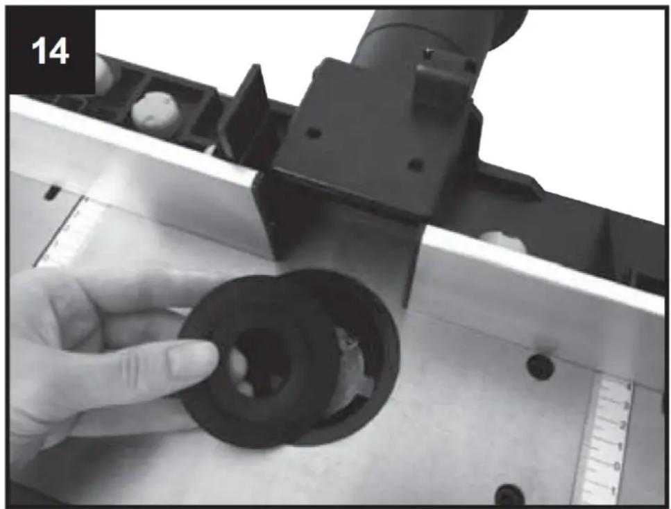
1. Installing and changing the clamping sleeves for top spindle moulders (Fig. 16, 13)
- Before changing the clamping sleeves, pull the power supply plug of your machine. Select the clamping sleeve matching the diameter of your cutter head.
- Remove the reducing piece from the table opening, Fig. 14.
- Lock the spindle with the button at the bottom of the spindle, Fig. 16.
- Release the safety nut of the clamping sleeve using the key supplied, Fig. 15.
- Insert the clamping sleeve in the nut, or remove it.
- Firmly tighten the nut in the clamp while keeping the spindle locked. Before every use of the machine make sure that the cutting tool is firmly clamped at the end of the spindle.
- Set the reducing piece for the opening back to its original position.
- Adjust the fence, as required, by means of the scale on the table.
- Connect the dust extractor unit. It is highly recommended to connect a dust extractor unit (or system) in order to keep the opening free from chips, to cool the motor, and to facilitate the work piece feed.
- Reconnect the machine to the power supply.
natural_image
Close-up of a hand adjusting a black mechanical component with a ruler for scale (no visible text or symbols)
natural_image
Close-up of a hand turning a mechanical component with a wrench, no visible text or symbols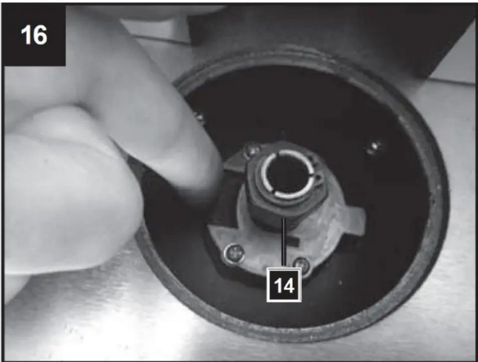
2. Setting the moulding fence
The use of the fence is a must. Every job must be looked at separately. At every new use you must make sure that the guards are correctly installed and adjusted. For every new use, each pressure piece on the fence must be newly set.
Make sure that all the bolts are firmly tightened before you start moulding.
3. Use of the table rings
The table rings must be used in order to reduce the spacing between table and spindle to a minimum. Before switching on the machine systematically check the table rings supplied for their correct seat.
Check whether you have chosen the correct ring for the corresponding cutting tool and its installation height, in order to reduce the risk of work piece tilting at passing the opening. The reduction piece (table ring) must enclose the cutter head as far as possible.
8. Adjustments
Adjust the number of revolutions Fig. 17, 20
The speed adjustment of the machine has 6 stages.
- Determine the optimal number of revolutions by a sample cut in a piece of waste material.
Note: The use of the correct number of revolutions increases the life-span of the drill. It, also, affects the worked surface of the work piece.
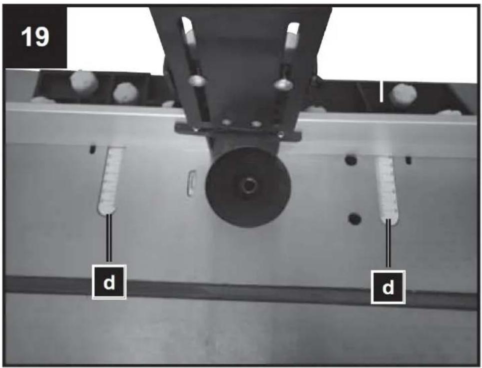
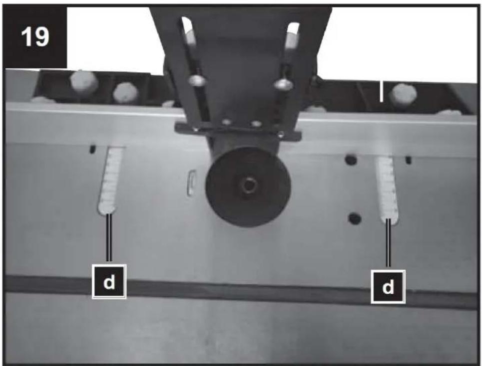
Adjust the rabbet, Fig. 18, 19
- The rabbit is to be stopped to the size of the work piece and the milling tool.
- Loosen the 2 plastic cap screws (b) on the back of the fence.
Set the stops and pressure devices such that they ensure the safe guidance of the workpiece at the input and output section of the machine.
- Push the rabbit to the rear or forward of the desired position. Use scale (c) on the table in order to determine the distance and take note of the drill centre.
- Re-tighten the 2 plastic cap screws (Fig. 19, b) on the back to keep the fence in this position.
Adjust the rabbet for error, Fig. 18, 19
- Error from wood is the material from wood left from the drill exiting, more thinly than the material, on the right side.
- The left fence must be adjusted to the thinner material. It supports the material and ensures a more exact cut. To do this, loosen the plastic cap screws, push the fence to the front and tighten it.

natural_image
Top-down view of an orange industrial control panel with a red indicator light and a small red device (no text or symbols visible)

| 20 | ∅ [mm] | ||||||
| ≤40 | 8 | 19 | 29 | 35 | 38 | 39 | |
| ≤60 | 15 | 26 | 36 | 40 | 49 | 59 | |
| ≤80 | 21 | 32 | 42 | 50 | 60 | 69 | |
| [min-1] | 11500 | 13000 | 16000 | 18500 | 21000 | 24000 | |
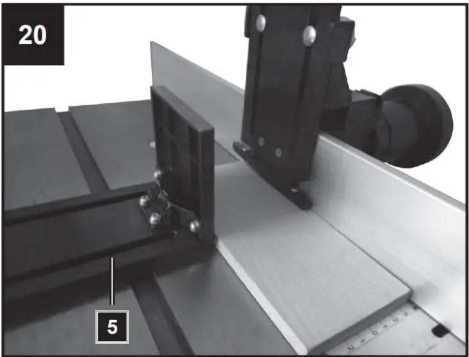
Installing and adjusting the pressure limits, Fig. 20
The pressure limits (5) are designed so that the work piece is held on the spot and setback is avoided.
- Drive milling cutter to the lowest position
- Insert the workpiece to be machined and press the pressure bar onto the workpiece with light pressure.
- Remove workpiece.
- Set the milling cutter to the desired height (see: Setting the working depth).
Adjust the Cross-cutting jig, Fig. 21
- Slide horizontal along the table the cross-cutting jig (8) in order to implement clean up error and mitre cuts.
- In order to stop the jig at the desired angle, loosen the locking knob of the cross-cutting jig and turn this to the desired angle.
Tighten the locking knob of the jig (8) again.
- Always make a sample cut in a piece of waste material in order to guarantee that the attitudes are correct.
natural_image
Mechanical assembly with metal components and a numbered label (20 and 5), no readable text or symbols beyond labels
Switching on and off
Make sure that all keys and adjusting tools are well away from the spare desk that the attitudes are installed in full and all safety covers are kept.
“O”-OFF
“I” - ON
This machine uses an electromagnetic switch for optimal security. Whenever the current is interrupted the machine stops immediately.
To restart the machine the green button must be pushed again.
9. Utilization of the machine
- Insert an appropriate milling cutter in the tool holder and secure this by tightening the tool holder nut (Fig. 17, item 14).
• Fit and secure the cutting knives. - Adjust the speed and adjust the output fence in such a way that the material cut is supported and a compensation for the material removed is achieved.
- Switch the machine on.
- Make sure the work piece is firmly pressed against the fence.
- Push the work piece softly from right to left against the turning direction of the tool.
- Keep your forwarding speed constant. Do not push too fast – it would slow down the motor too much.
- Feeding the work piece too fast will result in a poor cutting quality. There is also the risk of damaging the cutting knives or the motor.
- Feeding the work piece too slow will result in burnt spots on the work piece.
- With very hard wood and important cuts it can be necessary to work progressively in several cuts until the desired depth is achieved.
- The correct intake speed depends on the cutter size, the material type of the work piece, and the cutting depth. It is recommended to practise first with a piece of scrap wood in order to determine the correct intake speed and the dimensions.
- Switch the machine off by pressing the red cover.
- The machine is fitted with an overload switch (13) to protect the motor. In the event of an overload, the machine will cut out automatically. After a short time, the overload switch (13) can be reset again.
10. Cleaning, maintenance
General maintenance measures
- Wipe chips and dust off the machine from time to time using a cloth. In order to extend the service life of the tool, oil the rotary parts once monthly.
- Do not oil the motor.
- When cleaning the plastic do not use corrosive products.

WARNING! Before cleaning, adjustment, maintenance or repair work, disconnect the power cord from the main power supply!
Cleaning
- Keep all safety devices, air vents and the motor housing free of dirt and dust as far as possible. Wipe the equipment with a clean cloth or blow it with compressed air at low pressure.
-
We recommend that you clean the device immediately each time you have finished using it.
-
Clean the equipment regularly with a moist cloth and some soft soap. Do not use cleaning agents or solvents; these could attack the plastic parts of the equipment. Ensure that no water can seep into the device. The ingress of water into an electric tool increases the risk of an electric shock.
- The sawdust ejection and/or dust exhauster should be cleaned at regular intervals.
- Never spray water on the machine!
Cutting tool
Resin must be cleaned off the knife (21), latch (22) and knife block (23) at regular intervals. Clean these components with an appropriate resin remover.
Service information
Please note that the following parts of this product are subject to normal or natural wear and that the following parts are therefore also required for use as consumables.
Wear parts:* carbon brushes, planer blades
* Not necessarily included in the scope of delivery!
11. Storage
Store the equipment and accessories out of children's reach in a dark and dry place at above freezing temperature. The ideal storage temperature is between 5 and 30^ .
- Store the electric tool in its original packaging.
- Cover the electrical tool in order to protect it from dust and moisture.
- Store the operating manual with the electrical tool.
12. Electrical Connection

WARNING! Electric shock! There is a risk of an injury caused by electric shock!
Defective cable or plug may cause electric shock. Avoid body contact with earth parts to protect yourself from electric shocks.

Operation is only allowed with a safety switch against stray current (RCD max. stray current of
Insert the plug of the electrical cable in a socket of suitable shape, voltage and frequency complying with current regulations.
Do not pull the service cable to pull the plug out of socket.
The electric motor is connected in a ready-to-operate state. The connection corresponds to the relevant VDE and DIN regulations.
The mains connection at the customer's work place and the extension cable used must correspond to these regulations.
Important information
In the event of an overloading the motor will switch itself off. After a cool-down period (time varies) the motor can be switched back on again.
Faulty electrical connecting leads
Insulation damage often occurs at electrical connecting leads.
Causes include:
- Pressure marks caused when connecting leads are run through windows or the cracks of doors.
- Folds caused by the improper attachment of running of the connecting leads.
- Cuts resulting from the crossing of the connecting lead.
• Insulation damages caused by the ripping out of the connecting lead from the wall socket. - Cracks due to the ageing of the insulation.
Faulty electrical connecting leads such as these may not be used and are highly dangerous due to the insulation damage.
Check electrical connecting leads regularly for damage. Ensure that the connecting lead is not attached to the mains supply when you are checking it. Electrical connecting leads must correspond to the relevant VDE and DIN regulations. Only use connecting leads with the code H05VV-F.
The type designation must be printed on the connecting lead by regulation.
AC motor
- The supply voltage must be 230 volt / 50 Hz.
- Extension leads up to 25 m in length must have a cross-section of 1.5 mm ^2 , > 25 m length / 2,5 mm ^2 . Connections and repairs of electrical equipment may only be performed by a qualified electrician.
Please give the following information if you have any enquiries:
- Kind of current
• Machine type label data
• Data on the main label
13. Troubleshooting
The determination of the causes of these interference and their elimination always require heightened attention and caution. Pull the mains plug!
In the following are some of the most common interferences and their causes listed. If you cannot correct faults and errors with the machine, please contact your dealer.
| Disturbance | Probable cause | Help |
| Machine cannot be switched on | No mains voltage available. Carbon brush conductors worn out. | Control Voltage supplyBring Machine into the service centre |
| Machine switches off during the no-load operation independently | Power failure | Control Net-lateral Pre-fuseThe machine does not restart by the inserted under-voltage protection automatically and must again be switched on after tension return. |
| Machine remains during working on standstill | Response of the overload protection because of blunt measurers or of too large feed motion and/or thickness of chip | Before continuing with work exchange measurers and/or wait for cooling of the engine. |
| Number of revolutions drops during the treatment | Too large splinter acceptanceToo large feed motionMilling cutter blunt | Reduce Splinter acceptanceReduce Feed speedReplace milling cutter |
| Careless milling picture | Milling cutter bluntUneven feed motion | Replace milling cutterWork with constant pressure and reduced feed motion |
| Splinter ejection clogs (without | Too large splinter acceptance | Reduce Splinter acceptance |
| exhaust) | Milling cutter bluntToo wet wood | Exchange milling cutter |

natural_image
Diagram showing a curved arrow moving through a circular symbol and a wavy line with an arrow, no text or labels present.
natural_image
Black metal mechanical component with multiple ports and mounting holes (no visible text or symbols)
natural_image
Mechanical assembly component with a central cylindrical shaft and mounting bracket (no visible text or symbols)
natural_image
Close-up of a mechanical assembly with a black plastic frame and mounting bracket (no visible text or symbols)natural_image
Mechanical assembly with black plastic components and white bolts, no visible text or symbols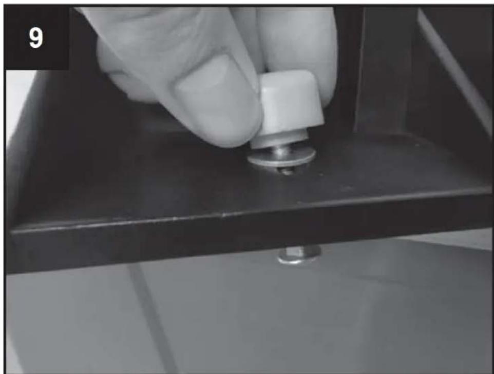
natural_image
Close-up of a hand pressing a small metallic knob on a dark surface, no visible text or symbols
natural_image
Experimental setup with a mechanical component and a thermometer, no visible text or symbols
natural_image
Mechanical assembly with metal components and white bolts, no visible text or symbolsnatural_image
Close-up of a hand holding a metal bracket on a metal workbench, with no visible text or symbols.
natural_image
Industrial machine component with two metallic parts and a central black frame, no visible text or symbolsnatural_image
Close-up of a hand adjusting a black mechanical component with a magnified inset showing internal features (no text or symbols visible)
natural_image
Close-up of a hand turning a mechanical component with a wrench, no visible text or symbols
natural_image
Top-down view of an orange industrial control panel with a red indicator light and a small red device (no text or symbols visible)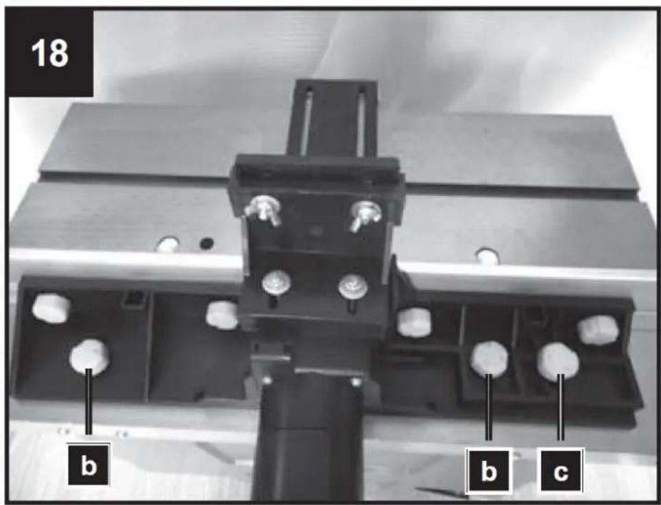

| 20 | ∅ [mm] | ||||||
| ≤40 | 8 | 19 | 29 | 35 | 38 | 39 | |
| ≤60 | 15 | 26 | 36 | 40 | 49 | 59 | |
| ≤80 | 21 | 32 | 42 | 50 | 60 | 69 | |
| [min-1] | 11500 | 13000 | 16000 | 18500 | 21000 | 24000 | |
natural_image
Mechanical assembly with metal components and a numbered label (20 and 5), no readable text or symbols beyond labels

natural_image
Black metal mechanical component with multiple ports and mounting holes (no visible text or symbols)
natural_image
Mechanical assembly with a black cylindrical component mounted on a metal frame, no visible text or symbols
natural_image
Close-up of a mechanical device with a black plastic housing and mounting bracket, mounted on a wooden surface (no visible text or symbols)natural_image
Mechanical assembly with black plastic components and white spherical holes (no text or symbols visible)
natural_image
Close-up of a hand pressing a small metallic component on a dark surface, no visible text or symbols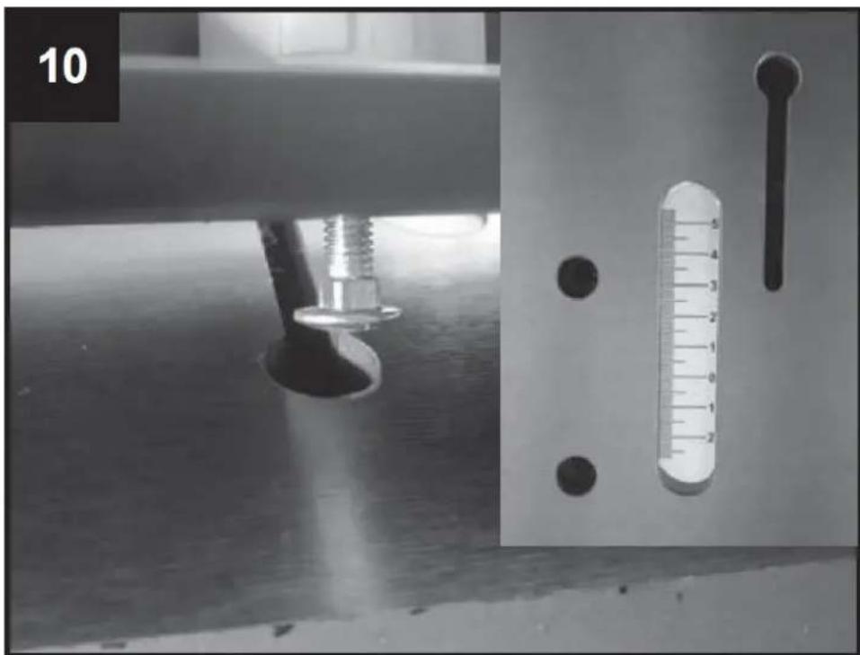
natural_image
Experimental setup with a mechanical component and a thermometer, no visible text or symbols
natural_image
Mechanical assembly with metal components and white bolts, no visible text or symbolsnatural_image
Close-up of a hand holding a metal bracket on a metal workbench, with no visible text or symbols.
natural_image
Industrial machine component with two metallic parts and a central black frame, no visible text or symbolsnatural_image
Close-up of a hand adjusting a black mechanical component with a ruler for scale (no visible text or symbols)
natural_image
Close-up of a hand turning a mechanical component with a wrench, no visible text or symbols
2. Nastavení lišty
natural_image
Top-down view of an orange industrial control panel with a red indicator light and a small red device (no text or symbols visible)

| 20 | ∅ [mm] | ||||||
| ≤40 | 8 | 19 | 29 | 35 | 38 | 39 | |
| ≤60 | 15 | 26 | 36 | 40 | 49 | 59 | |
| ≤80 | 21 | 32 | 42 | 50 | 60 | 69 | |
| [min-1] | 11500 | 13000 | 16000 | 18500 | 21000 | 24000 | |
natural_image
Mechanical assembly with metal components and a numbered label (20 and 5), no readable text or symbols beyond labels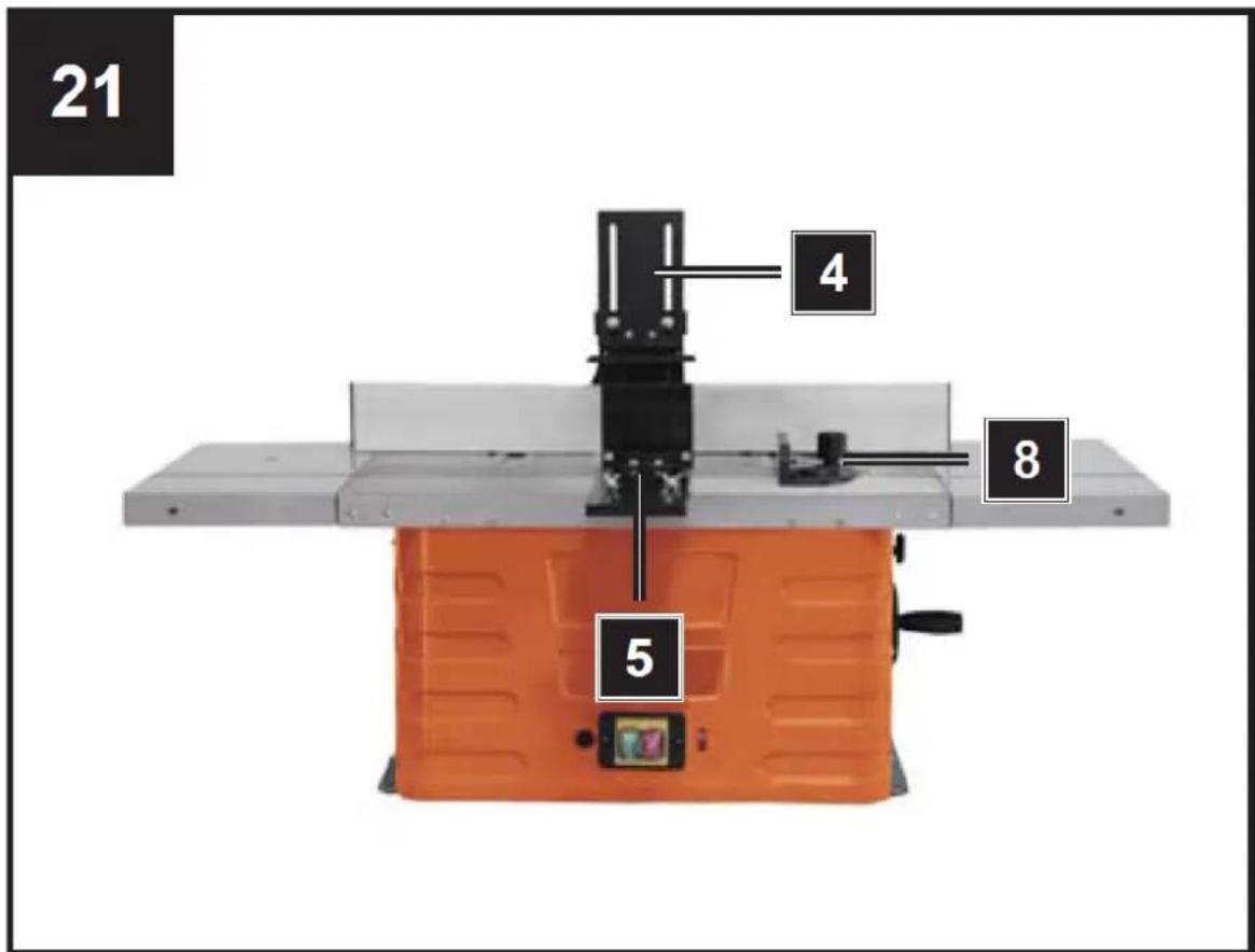
Zapínání a vypínání
natural_image
Black metal mechanical component with multiple ports and mounting holes (no visible text or symbols)
natural_image
Mechanical assembly component with a central cylindrical shaft and mounting bracket (no visible text or symbols)
natural_image
Close-up of a mechanical assembly with a black plastic frame and mounting bracket (no visible text or symbols)natural_image
Close-up of a mechanical assembly with multiple bolt holes and a black cylindrical component (no visible text or symbols)
natural_image
Close-up of a hand pressing a small metallic component on a dark surface, no visible text or symbols
natural_image
Experimental setup with a mechanical component and a thermometer, no visible text or symbols
natural_image
Mechanical assembly with metal components and white cylindrical elements, no visible text or symbolsnatural_image
Close-up of a hand holding a metal bracket on a metal workbench, with no visible text or symbols.
natural_image
Industrial machine component with two metallic parts and a central black frame, no visible text or symbolsnatural_image
Close-up of a hand adjusting a mechanical component with a circular dial and a ruler for scale (no visible text or symbols)
natural_image
Close-up of a hand turning a mechanical component with a wrench, no visible text or symbols
natural_image
Top-down view of an orange industrial control panel with a red indicator light and a small red device (no text or symbols visible)

| 20 | ∅ [mm] | ||||||
| ≤40 | 8 | 19 | 29 | 35 | 38 | 39 | |
| ≤60 | 15 | 26 | 36 | 40 | 49 | 59 | |
| ≤80 | 21 | 32 | 42 | 50 | 60 | 69 | |
| [min-1] | 11500 | 13000 | 16000 | 18500 | 21000 | 24000 | |
natural_image
Mechanical assembly with metal components and a numbered label (20 and 5), no readable text or symbols beyond labels
Allumer et éteindre
natural_image
Black metal mechanical component with multiple ports and mounting holes (no visible text or symbols)
natural_image
Mechanical assembly component with a central cylindrical shaft and mounting bracket (no visible text or symbols)
natural_image
Close-up of a mechanical assembly with a black plastic frame and mounting bracket (no visible text or symbols)natural_image
Close-up of a mechanical assembly with black plastic components and white bolts (no visible text or symbols)
natural_image
Close-up of a hand pressing a small metallic component on a dark surface, no visible text or symbols
natural_image
Experimental setup with a mechanical component and a thermometer, no visible text or symbols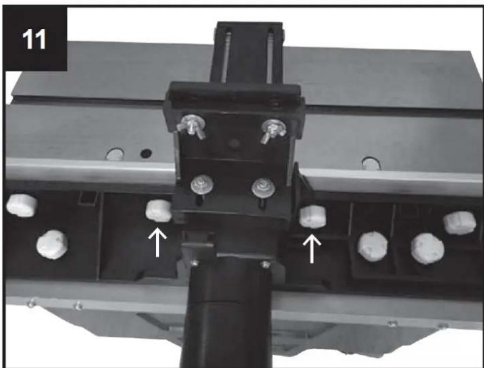
natural_image
Mechanical assembly with black components and white bolts, no visible text or symbolsnatural_image
Close-up of a hand holding a small metal bracket on a metal workbench, with no visible text or symbols.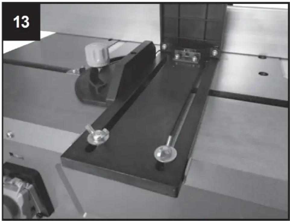
natural_image
Industrial machine component with two metallic parts and a central black frame, no visible text or symbolsnatural_image
Close-up of a hand adjusting a mechanical component with a circular dial and ruler for scale (no visible text or symbols)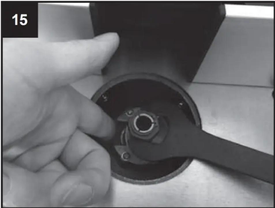
natural_image
Close-up of a hand turning a mechanical component with a wrench, no visible text or symbols
natural_image
Top-down view of an orange industrial control panel with a red indicator light and a small red device (no text or symbols visible)

| 20 | ∅ [mm] | ||||||
| ≤40 | 8 | 19 | 29 | 35 | 38 | 39 | |
| ≤60 | 15 | 26 | 36 | 40 | 49 | 59 | |
| ≤80 | 21 | 32 | 42 | 50 | 60 | 69 | |
| [min-1] | 11500 | 13000 | 16000 | 18500 | 21000 | 24000 | |
natural_image
Mechanical assembly with metal components and a numbered label (20 and 5), no readable text or symbols beyond labels21

natural_image
Mechanical component with black plastic parts and mounting holes (no visible text or symbols)
natural_image
Mechanical assembly component with a central cylindrical shaft and mounting bracket (no visible text or symbols)
natural_image
Close-up of a mechanical assembly with a black plastic frame and mounting bracket (no visible text or symbols)natural_image
Close-up of a mechanical assembly with black plastic components and white bolts (no visible text or symbols)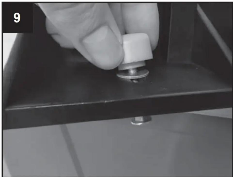
natural_image
Close-up of a hand pressing a small metallic component on a dark surface, no visible text or symbols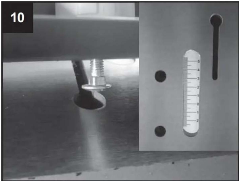
natural_image
Experimental setup with a mechanical component and a thermometer, no visible text or symbols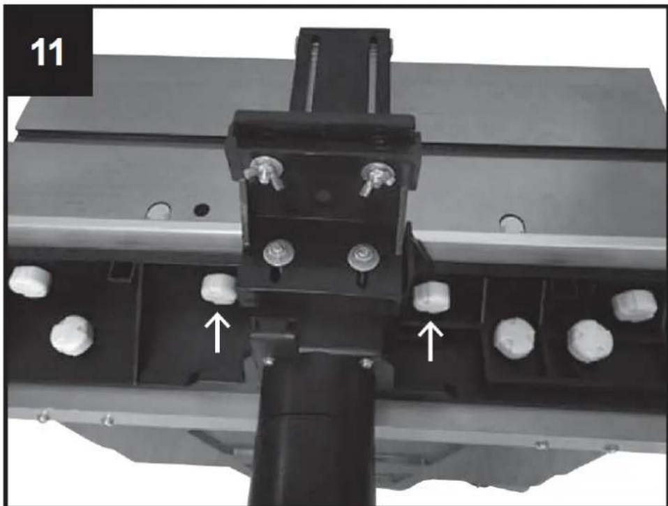
natural_image
Mechanical assembly with metal components and white cylindrical elements, no visible text or symbolsnatural_image
Close-up of a hand holding a metal bracket on a metal workbench, with no visible text or symbols.
natural_image
Industrial machine component with two metallic parts and a central black frame, no visible text or symbolsnatural_image
Close-up of a hand adjusting a black mechanical component with a circular hole, next to a ruler for scale (no visible text or symbols)
natural_image
Close-up of a hand turning a mechanical component with a wrench, no visible text or symbols
natural_image
Top-down view of an orange industrial control panel with a red indicator light and a small red device (no text or symbols visible)
| 20 | ∅ [mm] | ||||||
| ≤40 | 8 | 19 | 29 | 35 | 38 | 39 | |
| ≤60 | 15 | 26 | 36 | 40 | 49 | 59 | |
| ≤80 | 21 | 32 | 42 | 50 | 60 | 69 | |
| [min-1] | 11500 | 13000 | 16000 | 18500 | 21000 | 24000 | |
natural_image
Mechanical assembly with metal components and a numbered label (20 and 5), no readable text or symbols beyond labels
Encendido y apagado
natural_image
Diagram showing a curved arrow moving through a circular symbol and a wavy line with an arrow, no text or labels present.natural_image
Mechanical component with black plastic parts and mounting holes (no visible text or symbols)
natural_image
Mechanical assembly component with a central cylindrical shaft and mounting bracket (no visible text or symbols)
natural_image
Close-up of a mechanical assembly with a black plastic frame and mounting bracket (no visible text or symbols)natural_image
Mechanical assembly with black plastic components and white spherical pins (no visible text or symbols)
natural_image
Close-up of a hand pressing a small metallic component on a dark surface, no visible text or symbols
natural_image
Experimental setup with a mechanical component and a thermometer, no visible text or symbols
natural_image
Mechanical assembly with metal components and white cylindrical elements, no visible text or symbolsnatural_image
Close-up of a hand holding a metal bracket on a metal workbench, with no visible text or symbols.
natural_image
Industrial machine component with two metallic parts and a central black frame, no visible text or symbolsnatural_image
Close-up of a hand adjusting a mechanical component with a circular dial and ruler for scale (no visible text or symbols)natural_image
Top-down view of an orange industrial control panel with a red indicator light and a small red device (no text or symbols visible)

| 20 | ∅ [mm] | ||||||
| ≤40 | 8 | 19 | 29 | 35 | 38 | 39 | |
| ≤60 | 15 | 26 | 36 | 40 | 49 | 59 | |
| ≤80 | 21 | 32 | 42 | 50 | 60 | 69 | |
| [min-1] | 11500 | 13000 | 16000 | 18500 | 21000 | 24000 | |
natural_image
Mechanical assembly with metal components and a numbered label (20 and 5), no readable text or symbols beyond labels
Be- és kikapcsolás

natural_image
Mechanical component with black plastic housing and mounting bracket (no visible text or symbols)
natural_image
Mechanical assembly with a black cylindrical component mounted on a metal frame, no visible text or symbols
natural_image
Close-up of a mechanical device with a black plastic housing and mounting bracket, mounted on a wooden surface (no visible text or symbols)natural_image
Mechanical assembly with black plastic components and white spherical holes (no text or symbols visible)
natural_image
Close-up of a hand pressing a small metallic component on a dark surface, no visible text or symbols
natural_image
Experimental setup with a mechanical component and a thermometer, no visible text or symbols
natural_image
Mechanical assembly with metal components and white cylindrical elements, no visible text or symbolsnatural_image
Close-up of a hand holding a metal bracket on a metal workbench, with no visible text or symbols.
natural_image
Industrial machine component with two metallic parts and a central black frame, no visible text or symbolsnatural_image
Close-up of a hand adjusting a black circular component on a mechanical device, with a ruler for scale (no visible text or symbols)
natural_image
Close-up of a hand turning a mechanical component with a wrench, no visible text or symbols
natural_image
Mechanical assembly with metal components and a numbered label (20 and 5), no readable text or symbols beyond labels
Tænding og slukning
natural_image
Black metal mechanical component with multiple ports and mounting holes (no visible text or symbols)
natural_image
Mechanical assembly with a black cylindrical component mounted on a metal frame, no visible text or symbols
natural_image
Close-up of a mechanical device with a black plastic housing and mounting bracket, mounted on a wooden surface (no visible text or symbols)natural_image
Mechanical assembly with black plastic components and white spherical holes (no text or symbols visible)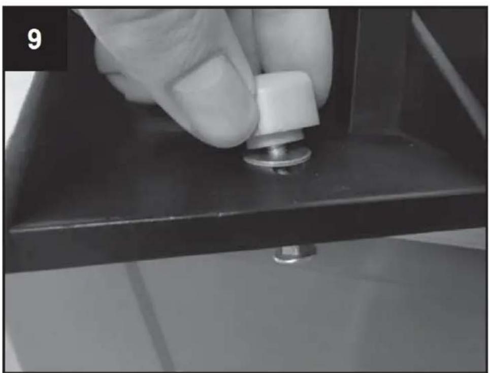
natural_image
Close-up of a hand pressing a small metallic knob on a dark surface, no visible text or symbols
natural_image
Experimental setup with a mechanical component and a thermometer, no visible text or symbols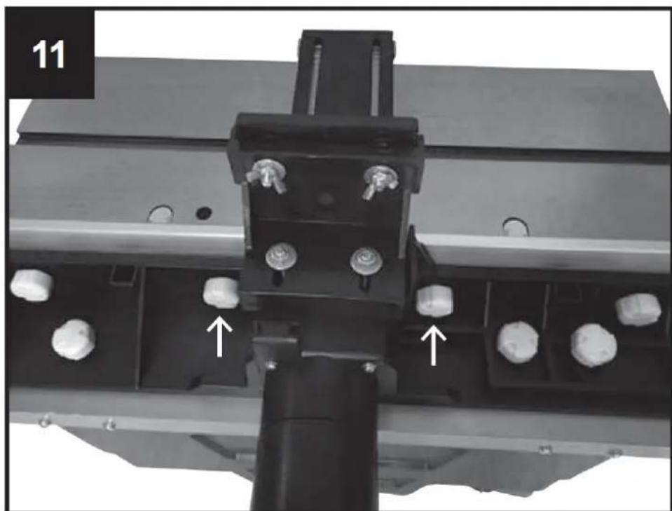
natural_image
Mechanical assembly with metal components and white bolts, no visible text or symbolsTakapotkuturva-aidan komponentit
natural_image
Close-up of a hand holding a metal bracket on a metal workbench, with no visible text or symbols.
natural_image
Industrial machine component with two metallic parts and a central black frame, no visible text or symbolsTyösyvyyden sovitus
natural_image
Close-up of a hand adjusting a black circular component on a mechanical device, with a ruler for scale (no visible text or symbols)
natural_image
Close-up of a hand turning a mechanical component with a wrench, no visible text or symbols
natural_image
Top-down view of an orange industrial control panel with a red indicator light and a small red device (no text or symbols visible)

| 20 | ∅ [mm] | ||||||
| ≤40 | 8 | 19 | 29 | 35 | 38 | 39 | |
| ≤60 | 15 | 26 | 36 | 40 | 49 | 59 | |
| ≤80 | 21 | 32 | 42 | 50 | 60 | 69 | |
| [min-1] | 11500 | 13000 | 16000 | 18500 | 21000 | 24000 | |
natural_image
Mechanical assembly with metal components and a numbered label (20 and 5), no readable text or symbols beyond labels
natural_image
Diagram showing a curved arrow moving through a circular symbol and a wavy line with an arrow, no text or labels present.natural_image
Black metal mechanical component with multiple ports and mounting holes (no visible text or symbols)
natural_image
Mechanical assembly component with a central cylindrical shaft and mounting bracket (no visible text or symbols)
natural_image
Close-up of a mechanical assembly with a black plastic frame and mounting bracket (no visible text or symbols)natural_image
Close-up of a mechanical assembly with multiple bolt holes and a black cylindrical component (no visible text or symbols)
natural_image
Close-up of a hand pressing a small metallic component on a dark surface, no visible text or symbols
natural_image
Experimental setup with a mechanical component and a thermometer, no visible text or symbols
natural_image
Mechanical assembly with black components and white bolts, no visible text or symbolsnatural_image
Close-up of a hand holding a metal bracket on a metal workbench, with no visible text or symbols.
natural_image
Industrial machine component with two metallic parts and a central black frame, no visible text or symbolsnatural_image
Close-up of a hand adjusting a mechanical component with a circular dial and a ruler for scale (no visible text or symbols)
natural_image
Close-up of a hand turning a mechanical component with a wrench, no visible text or symbols
natural_image
Top-down view of an orange industrial control panel with a red indicator light and a small red device (no text or symbols visible)

| 20 | ∅ [mm] | ||||||
| ≤40 | 8 | 19 | 29 | 35 | 38 | 39 | |
| ≤60 | 15 | 26 | 36 | 40 | 49 | 59 | |
| ≤80 | 21 | 32 | 42 | 50 | 60 | 69 | |
| [min-1] | 11500 | 13000 | 16000 | 18500 | 21000 | 24000 | |
natural_image
Mechanical assembly with metal components and a numbered label (20 and 5), no readable text or symbols beyond labels
natural_image
Black metal mechanical component with multiple ports and mounting holes (no visible text or symbols)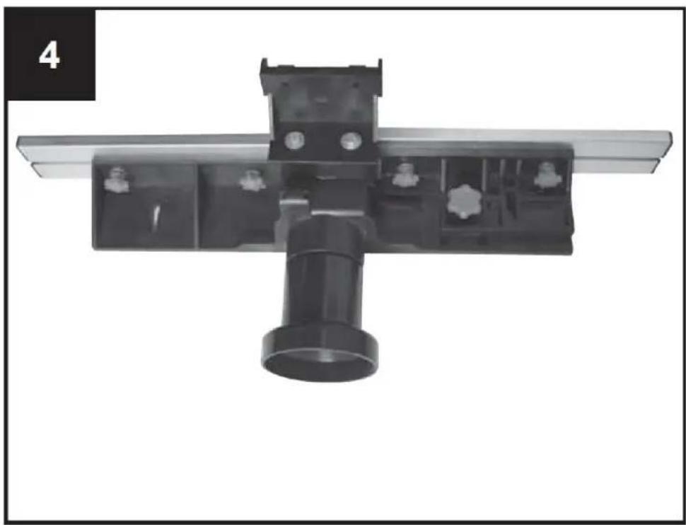
natural_image
Mechanical assembly with a black cylindrical component mounted on a metal frame, no visible text or symbols
natural_image
Close-up of a mechanical device with a black plastic housing and mounting bracket, mounted on a wooden surface (no visible text or symbols)natural_image
Mechanical assembly with black plastic components and white spherical holes (no text or symbols visible)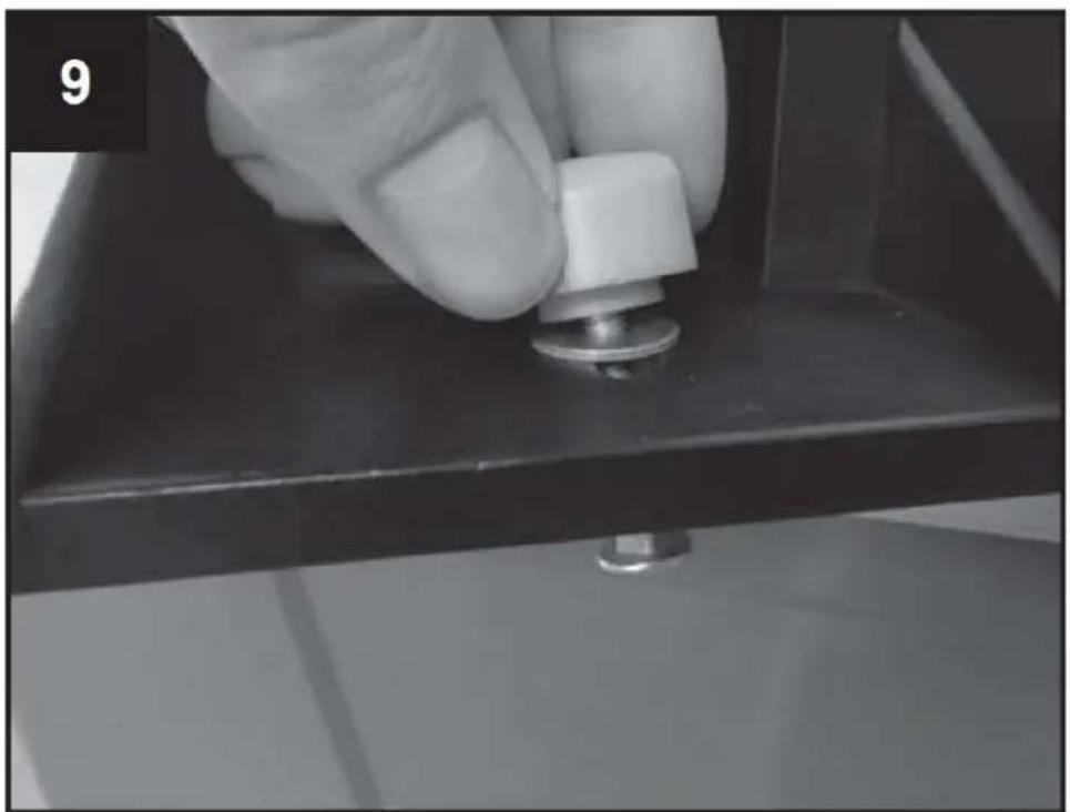
natural_image
Close-up of a hand pressing a small metallic component on a dark surface, no visible text or symbols
natural_image
Experimental setup with a mechanical component and a thermometer, no visible text or symbols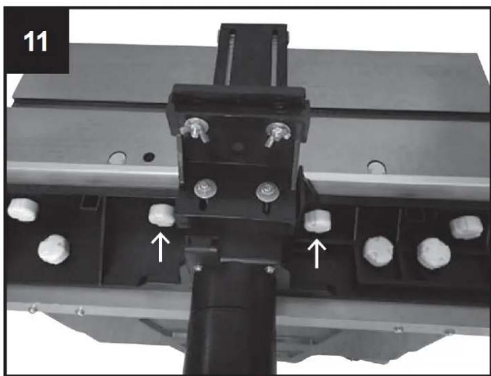
natural_image
Mechanical assembly with metal components and white cylindrical components, no visible text or symbolsTilbakeslagssikkerhetsgjerdekomponenter
1 Sikkerhetsgjerde for tilbakeslag
1 monteringsbrakett
natural_image
Close-up of a hand holding a metal bracket on a metal workbench, with no visible text or symbols.
natural_image
Industrial machine component with two metallic parts and a central black frame, no visible text or symbolsnatural_image
Close-up of a hand adjusting a black mechanical component with a ruler for scale (no visible text or symbols)
natural_image
Close-up of a hand turning a mechanical component with a wrench, no visible text or symbols
natural_image
Top-down view of an orange industrial control panel with a red indicator light and a small red device (no text or symbols visible)
| 20 | ∅ [mm] | ||||||
| ≤40 | 8 | 19 | 29 | 35 | 38 | 39 | |
| ≤60 | 15 | 26 | 36 | 40 | 49 | 59 | |
| ≤80 | 21 | 32 | 42 | 50 | 60 | 69 | |
| [min-1] | 11500 | 13000 | 16000 | 18500 | 21000 | 24000 | |
natural_image
Mechanical assembly with metal components and a numbered label (20 and 5), no readable text or symbols beyond labels
Slår av og på
natural_image
Mechanical component with black plastic parts and mounting holes (no visible text or symbols)
natural_image
Mechanical assembly component with a central cylindrical shaft and mounting bracket (no visible text or symbols)
natural_image
Close-up of a mechanical assembly with a black plastic frame and mounting bracket (no visible text or symbols)natural_image
Mechanical assembly with black plastic components and white spherical elements (no visible text or symbols)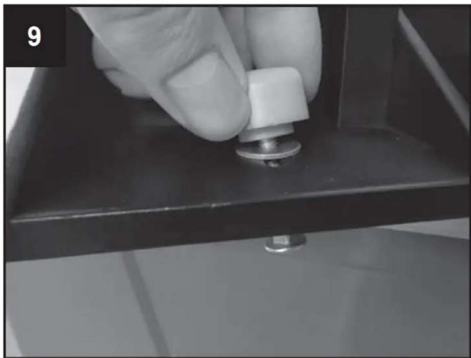
natural_image
Close-up of a hand pressing a small metallic component on a dark surface, no visible text or symbols
natural_image
Experimental setup with a mechanical component and a thermometer, no visible text or symbols
natural_image
Mechanical assembly with black components and white bolts, no visible text or symbolsnatural_image
Close-up of a hand holding a metal bracket on a metal workbench, with no visible text or symbols.
natural_image
Industrial machine component with two metallic parts and a central black frame, no visible text or symbolsnatural_image
Close-up of a hand adjusting a black mechanical component with a circular hole, no visible text or symbols
natural_image
Close-up of a hand turning a mechanical component with a wrench, no visible text or symbols
natural_image
Top-down view of an orange industrial control panel with a red indicator light and a small red device (no text or symbols visible)

| 20 | ∅ [mm] | ||||||
| ≤40 | 8 | 19 | 29 | 35 | 38 | 39 | |
| ≤60 | 15 | 26 | 36 | 40 | 49 | 59 | |
| ≤80 | 21 | 32 | 42 | 50 | 60 | 69 | |
| [min-1] | 11500 | 13000 | 16000 | 18500 | 21000 | 24000 | |
natural_image
Mechanical assembly with metal components and a numbered label (20 and 5), no readable text or symbols beyond labels
Slår på och av
natural_image
Black metal mechanical component with multiple ports and mounting holes (no visible text or symbols)
natural_image
Mechanical assembly component with a central cylindrical shaft and mounting bracket (no visible text or symbols)
natural_image
Close-up of a mechanical assembly with a black plastic frame and mounting bracket (no visible text or symbols)natural_image
Mechanical assembly with black plastic components and white spherical pins (no visible text or symbols)
natural_image
Close-up of a hand pressing a small metallic knob on a dark surface, no visible text or symbols
natural_image
Experimental setup with a mechanical component and a thermometer, no visible text or symbols
natural_image
Mechanical assembly with metal components and white bolts, no visible text or symbolsnatural_image
Close-up of a hand holding a metal bracket on a metal workbench, with no visible text or symbols.
natural_image
Industrial machine component with metal frame and adjustment knobs (no visible text or symbols)natural_image
Close-up of a hand adjusting a black mechanical component with a circular hole, no visible text or symbols
natural_image
Close-up of a hand turning a mechanical component with a wrench, no visible text or symbols
natural_image
Top-down view of an orange industrial control panel with a red indicator light and a small red device (no text or symbols visible)

| 20 | ∅ [mm] | ||||||
| ≤ 40 | 8 | 19 | 29 | 35 | 38 | 39 | |
| ≤ 60 | 15 | 26 | 36 | 40 | 49 | 59 | |
| ≤ 80 | 21 | 32 | 42 | 50 | 60 | 69 | |
| [min-1] | 11500 | 13000 | 16000 | 18500 | 21000 | 24000 | |
natural_image
Mechanical assembly with metal components and a numbered label (20 and 5), no readable text or symbols beyond labels
Ligar e desligar
natural_image
Black metal mechanical component with multiple ports and mounting holes (no visible text or symbols)
natural_image
Mechanical assembly with a black cylindrical component mounted on a metal frame, no visible text or symbols
natural_image
Close-up of a mechanical device with a black plastic housing and mounting bracket, mounted on a wooden surface (no visible text or symbols)natural_image
Mechanical assembly with black plastic components and white spherical holes (no text or symbols visible)
natural_image
Close-up of a hand pressing a small metallic component on a dark surface, no visible text or symbols
natural_image
Experimental setup with a mechanical component and a thermometer, no visible text or symbols
natural_image
Mechanical assembly with metal components and white cylindrical elements, no visible text or symbolsnatural_image
Close-up of a hand holding a metal bracket on a metal workbench, with no visible text or symbols.
natural_image
Industrial machine component with two metallic parts and a central black frame, no visible text or symbolsnatural_image
Close-up of a hand adjusting a mechanical component with a circular hole and ruler for scale (no visible text or symbols)
natural_image
Close-up of a hand turning a mechanical component with a wrench, no visible text or symbols
2. Nastavenie lišty
natural_image
Top-down view of an orange industrial control panel with a red indicator light and a small red device (no text or symbols visible)

| 20 | ∅ [mm] | ||||||
| ≤40 | 8 | 19 | 29 | 35 | 38 | 39 | |
| ≤60 | 15 | 26 | 36 | 40 | 49 | 59 | |
| ≤80 | 21 | 32 | 42 | 50 | 60 | 69 | |
| [min-1] | 11500 | 13000 | 16000 | 18500 | 21000 | 24000 | |
natural_image
Mechanical assembly with metal components and a numbered label (20 and 5), no readable text or symbols beyond labels
Zapínanie a vypínanie
For the disposal of the device please consider and act according to the national and local rules and regulations.
CONTACT
expondo Polska sp. z o.o. sp. k.