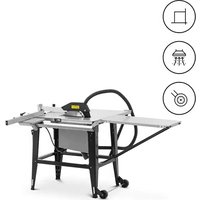
SBBD-2800MAX - Saw MSW - Free user manual and instructions
Find the device manual for free SBBD-2800MAX MSW in PDF.


| Product Type | Table Saw |
| Brand | MSW |
| Model | SBBD-2800MAX |
| Supply Voltage | 230 V~ / 50 Hz |
| Rated Power | 2000 W |
| Protection Class | I |
| IP Rating | IP44 |
| Motor Duty Cycle | S6 40% (4 min loaded / 6 min idling) |
| Dimensions (L × W × H) | 1690 × 1520 × 860 mm |
| Weight | 54 kg |
| Work Table Dimensions | 800 × 550 mm (+ extension 800 × 400 mm) |
| No-Load Speed | 2800 rpm |
| Cutting Depth at 90° | 83 mm |
| Cutting Depth at 45° | 49 mm |
| Blade Diameter | 315 mm (bore 30 mm) |
| Blade Thickness | 3 mm |
| Number of Teeth | 24 |
| Sound Power Level LwA | 105.1 dB(A) |
| Sound Pressure Level LpA | 98.1 dB(A) |
| Main Functions | Rip cuts, cross cuts, bevel cuts (0-45°), parallel guide, miter guide, dust extraction system |
| Maintenance and Cleaning | Clean with a soft non-abrasive cloth; do not immerse; use compressed air for ventilation slots |
| Safety | Blade guard, riving knife, emergency stop, overload protection, locking devices |
| Spare Parts and Reparability | Saw blade (standard ref. ∅315/30 mm), push stick, combination wrenches; repair by an authorized professional |
| General Information | CE compliant; indoor use; manufacturer warranty |
Frequently Asked Questions - SBBD-2800MAX MSW
User questions about SBBD-2800MAX MSW
0 question about this device. Answer the ones you know or ask your own.
Ask a new question about this device
Download the instructions for your Saw in PDF format for free! Find your manual SBBD-2800MAX - MSW and take your electronic device back in hand. On this page are published all the documents necessary for the use of your device. SBBD-2800MAX by MSW.
USER MANUAL SBBD-2800MAX MSW
natural_image
Close-up of a mechanical assembly with visible wiring and a labeled component 'f' (no text or symbols beyond label)natural_image
Close-up of a metal bracket with a diagonal beam and a black clip, no visible text or symbolsnatural_image
Close-up of a mechanical lever system with black and silver components and two metallic wheels (no text or symbols visible)natural_image
Hand holding a black metal clip attached to a white surface, next to a black metal bracket with serrated edges (no text or symbols visible)natural_image
Mechanical device with labeled parts (c and d) showing internal components and wiring (no readable text or symbols beyond labels)natural_image
Close-up of a black corrugated cable inserted into a mechanical bracket (no text or symbols visible)natural_image
Close-up of a black metal bracket with a bolt and arrow pointing to its side (no text or symbols visible)natural_image
Mechanical tool with protractor and lever assembly (no text or symbols visible)natural_image
Mechanical assembly diagram showing two vertical supports with directional arrows indicating movement or force (no text or symbols present)natural_image
Mechanical assembly with a metallic rod and directional arrows indicating force or movement (no text or symbols)natural_image
Mechanical assembly with arrows indicating direction of motion or force, no visible text or symbolsnatural_image
Mechanical assembly diagram showing a cam or roller mechanism with no visible text or symbolsnatural_image
Close-up of hands operating a metal cutting machine with visible cutting tools and components (no text or symbols)natural_image
Person in gloves handling a black mechanical component on a workbench (no visible text or symbols)natural_image
Person using a lathe machine to cut wood blocks on a metal workbench (no text or symbols visible)natural_image
Mechanical assembly diagram showing a clamping mechanism with metal components and mounting brackets (no text or symbols)natural_image
Close-up of hands installing or adjusting a black plastic cover on a metal tray (no text or symbols visible)natural_image
Close-up of hands operating a mechanical component with a tool, no visible text or symbolsThis User Manual has been translated for your convenience using machine translation. Reasonable efforts have been made to provide an accurate translation; however, no automated translation is perfect nor is it intended to replace human translators. The official User Manual is the English version. Any discrepancies or differences created in the translation are not binding and have no legal effect for compliance or enforcement purposes. If any questions arise related to the accuracy of the information contained in the User Manual, please refer to the English version of those contents which is the official version.
Technical data
| Parameter description Parameter value | |
| Product name | Table saw |
| Model | MSW-SBBD-2800MAX |
| Supply voltage [V~] / Frequency [Hz] | 230 / 50 |
| Rated power [W]. | 2000 |
| Safety class | I |
| IP class | IP44 |
| Electric motor duty cycle | S6 40% (4 min. under load / 6 min. idle without load) |
| Dimensions [width x depth x height; mm] | 1690 x 1520 x 860 |
| Weight [kg] | 54 |
| Working surface dimensions [mm] | 800 x 550 (+ 800 x 400) |
| Speed No load [rpm] | 2800 |
| Cutting depth | 83 mm at a 90° angle |
| 49 mm at a 45° angle | |
| Cutting disc parameters [mm] | ø315 (mounting hole ø30 mm) x 3 thickness; 24 teeth |
| Noise level LwA [dB (A)] | 105.1 |
| Sound pressure level LpA [dB(A)] | 98.1 |
1. General Description
The manual is intended to assist in safe and reliable use. The product is designed and manufactured strictly according to technical specifications using the latest technology and components and maintaining the highest quality standards.
CAREFULLY READ AND UNDERSTAND THIS MANUAL BEFORE STARTING THE WORK.
To ensure the long and reliable operation of the device, make sure to operate and maintain it properly following the guidelines in this instruction manual. The technical data and specifications in this manual are up-to-date. The manufacturer reserves the right to make changes to improve the quality. Taking the technical progress and the possibility of reducing noise into account, the unit is designed and built in such a way that risks resulting from noise emissions are reduced to the lowest possible level.
Explanation of symbols
| CE | The product complies with applicable safety standards. |
 | Read the manual before use. |
 | Recyclable product. |
 | CAUTION! or WARNING! or REMEMBER! describing a situation (general warning sign). |
 | Wear ear protection. Exposure to noise may cause hearing loss. |
 | Wear protective goggles. |
 | Wear a dusk mask (protecting the respiratory tract). |
 | Wear protective footwear. |
 | Use adjustable guards. | |
 | Wear a protective suit. | |
 | CAUTION! Risk of electric shock! | |
 | CAUTION! Warning against loud noise! | |
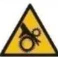 | CAUTION! Spinning elements! | |
 | Don't touch! | |
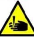 | CAUTION! Sharp, moving parts of the machine! Danger of injury or severing fingers/limbs. | |
 | For indoor use only. | |
 | Mark of the direction of continuous (rotary) operation of the device. | |
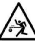 | WARNING - risk of kickback! |

CAUTION! The figures in this manual are illustrative only and may vary in some details from the actual appearance of the product.
2. Safety of use

CAUTION! Read all safety warnings and instructions. Failure to follow the warnings and instructions may result in electric shock, fire, and/or serious injury or death.
The term "device" or "product" in the warnings and the description of the instructions refers to:
Table saw
2.1. Electrical safety
a) The plug of this device must fit into the outlet. Do not modify the plug in any way. Original plugs and matching outlets reduce the risk of electric shock.
b) Av oid touching grounded parts, such as pipes, heaters, ovens, and refrigerators. There is an increased risk of electric shock if your body is grounded and touches the device while exposed to direct rain, wet pavement, or while working in a damp environment. If water enters the device, there is an increased risk of damage to the unit and electric shock.
c) Do not touch the device with wet or damp hands.
d) Do not use the cord in an unintended manner. Never use it to carry the device or to pull the plug out of the socket. Keep the cord away from heat sources, oil, sharp edges, or moving parts. Damaged or tangled cords increase the risk of electric shock.
e) D o not use the unit if the power cord is damaged or shows signs of wear. A damaged power cord should be replaced by a qualified electrician or the manufacturer's service department.
f) To avoid electric shock, do not immerse the cable, plug, or the device itself in water or other liquid. Do not use the appliance on wet surfaces.
g) CAUTION – DANGER TO LIFE! When cleaning or using the appliance, never immerse it in water or other liquids.
h) Do not use the appliance in rooms with very high humidity / in the immediate vicinity of water tanks!
i) Do not allow the machine to get wet. Risk of electric shock!
2.2. Safety in the workplace
a) Keep the work area tidy and well-lit. Disorder or poor lighting can lead to accidents. Be foresighted, watch what you are doing and use common sense when using the device.
b) If you have any doubts as to whether the product is working properly or if it is damaged, contact the manufacturer's service department.
c) Re pairs to the device may only be carried out by the manufacturer's service. Do not attempt to repair the product on your own!
d) In case of open flames or fire, use only dry powder or snow (CO2) fire extinguishers to extinguish the live equipment.
e) No children or unauthorized persons are allowed in the work area. (Inattention may result in loss of control of the unit.)
f) Use the unit in a well-ventilated area.
g) Dust and debris are generated during the operation of the device, please protect bystanders from their harmful effects.
h) Check the condition of the safety stickers regularly. Replace them if they are illegible.
i) Keep these instructions for use for future reference. If the product is to be handed over to a third party, hand it over with this user manual.
j) Keep packaging components and small installation parts out of the reach of children.
k) Keep the device away from children and animals.
I) When using this product together with other devices, also follow the other instructions for use.

Remember! Keep children and other bystanders safe while operating the equipment.
2.3. Personal safety
a) Do not operate this device if you are tired, ill, or under the influence of alcohol, drugs, or medication that could impair your ability to operate the device.
b) The unit may be operated by persons who are physically fit, capable of operating it, and appropriately trained, and who have read this instruction manual and have been trained in occupational safety and health.
c) The machine is not intended to be used by persons (including children) with reduced mental, sensory, or intellectual functions or persons who lack experience and/or knowledge unless they are supervised or have been instructed by a person responsible for their safety on how to operate the machine.
d) Use caution and common sense when operating this device. A moment's inattention during the operation may result in serious personal injury.
e) Use personal protective equipment as required when operating the unit as specified in Section 1 of the explanation of symbols. The use of appropriate, approved personal protective equipment reduces the risk of injury.
f) To prevent accidental start-up, make sure the switch is in the off position before connecting to a power source.
g) Do not overestimate your capabilities. Maintain body balance and equilibrium at all times during operation. This allows for better control of the machine in unexpected situations.
h) Do not wear loose clothing or jewelry. Keep hair, clothing, and gloves away from moving parts. Loose clothing, jewelry, or long hair can be caught in moving parts.
i) If the unit is provided with extraction connections, check that they are correctly connected and fixed. Using dust extraction can reduce dust hazards.
j) B before switching the unit on, remove any regulating tools or keys. Any tools or keys left in the rotating part of the unit may cause injury.
k) Eye, ear, and respiratory protection is recommended.
I) T he product is not a toy. Children should be watched to ensure that they do not play with the appliance.
m) Do not put your hands inside the working device!
2.4. Safe use of the device
a) D o not overload the device. Use tools that are suitable for the application. A correctly selected product will do a better and safer job for which it was designed.
b) Do not use the device if the ON/OFF switch does not function properly (does not turn on and off). Units that cannot be controlled by the switch are unsafe, cannot operate, and must be repaired.
c) Unplug the unit before making adjustments, changing accessories, or putting it away. This precaution reduces the risk of accidental start-up.
d) Di sconnect the device from the power supply before adjusting, cleaning, or servicing. This precaution reduces the risk of accidental start-up.
e) Keep unused product out of the reach of children and anyone unfamiliar with the device or this manual. Products are dangerous when used by inexperienced users.
f) Keep the product in good working order. Check before each use for general damage or damage to moving parts (cracks in parts and components or any other condition that may affect the safe operation of the device). If damaged, return the device for repair before use.
g) K eep the product out of the reach of children.
h) T o ensure the designed operational integrity of the device, do not remove factory-installed covers or loosen screws.
i) When transporting or moving the device from storage to the place of use, observe the health and safety rules for manual handling applicable in the country where the device is used.
j) Avoid situations in which the device stops under heavy loads during operation. This can cause overheating of the drive elements and consequent damage to the equipment.
k) Do not touch any moving parts or accessories unless the device is unplugged.
I) Do not move, shift, or rotate the device while in operation.
m) Do not leave the device switched on unattended.
n) Clean the device regularly to prevent permanent dirt build-up.
o) Do not process two workpieces at the same time.
p) Do not tamper with the device to alter its performance or design.
q) Keep the unit away from sources of fire and heat.
r) Do not overload the device.
s) When working with the device, we recommend special care to avoid serious injury or amputation of limb fragments.

CAUTION! Although the product has been designed to be safe and has adequate safeguards and despite the additional safety features provided to the user, there is still a slight risk of accident or injury when handling the product. Caution and common sense are advised when using the product.
3. Instructions for use
The device is designed for cutting objects with limited dimensions and made from suitable materials. The motor has an overload protection - in case of overheating, it will switch off automatically. Restarting will be possible after the device has cooled down.
• After each setting change, it is recommended to perform a control cut first
- After switching on the machine and before starting to cut, wait until the cutting disc has reached its maximum speed.
• Adapting the cutting discs:
- 24 teeth - soft materials, large amount of chips, rough cut;
- 48 teeth - hard materials, small amount of chips, precise cutting
• Safety tips for working with the device:
-
Check that all mounting hardware and accessories are securely fitted, in particular the blade guard.
During operation, take into account the external conditions (e.g. weather, lighting). -
Use the unit with safety guards whenever possible
Before starting, make sure that the cutting disc does not come into contact with any part of the housing or with the workpiece. - Never look directly into the laser beam with the naked eye.
Do not push the workpiece directly in line with the blade with your hands - if possible, always use a pusher or other element. - The use of a dust extraction system is recommended.
- Secure the workpiece (e.g. with the help of additional blocks, tables, etc.)
- Watch out for the kickback, which is frequent when working with such a device - closely observe the workpiece, do not exert too much pressure on the saw blades, and be especially careful when cutting irregularly shaped objects.
○ Make sure that there are no foreign bodies in the object to be cut, such as nails, screws, bolts, stones, etc.
- Despite using the unit as intended and taking the necessary precautions, there are always risk factors that cannot be completely ruled out, such as:
- touching the cutting disc in an unprotected place
○ being pulled in by a rotating cutting disc - kickback of cut objects and their remains
○ cracks in the cutting disc
o ejection of particles from defective cutting discs
○ damage to hearing due to the lack of appropriate or sufficient protection
○ harmful dusting of wood residues when used in confined spaces
The user is responsible for any damage resulting from misuse.
3.1. Product overview
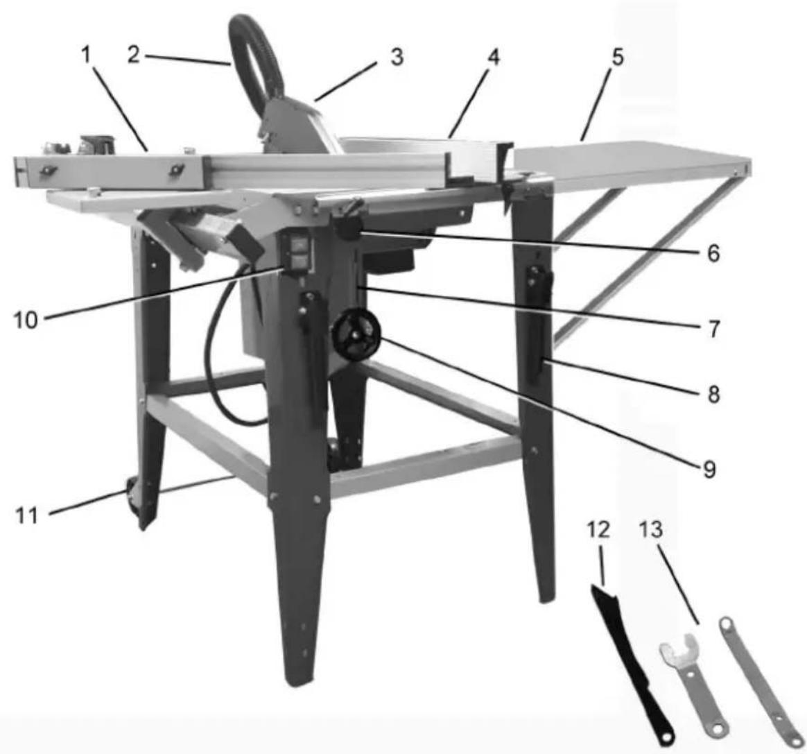
- An gle guide
- Dus t extraction hose
- B lade guard
- Pa rallel guide
- E xtension of the worktop
- B lade angle adjustment knob
- Blade height adjustment scale
- Tra nsport handle (x2)
- B lade height adjustment knob
- Po wer switch
- Transport wheels
- Pusher
- F lat wrenches
3.2. Preparation for operation
3.2.2 LOCATING THE DEVICE
EN
The device should be positioned in a way that ensures good circulation and freedom of maneuver for the operator. Maintain a minimum distance of 1 m from each wall of the unit. Keep the unit away from any hot surfaces. Always operate the unit on a level, stable, clean, fireproof, and dry surface and out of the reach of children and persons with impaired mental, sensory, and intellectual functions. Place the unit in such a way that the main plug can be reached at any time. Ensure that the power supply to the unit corresponds to that specified on the identification plate!
3.2.3 ASSEMBLY OF THE DEVICE a) STAND AND WORKTOP
- Make sure that the blade is hidden inside the unit by adjusting it with the height adjustment knob (b). Then place the stand upside down on the worktop - preferably on a soft surface so as not to damage it.
- Attach the suction connector (a) to the motor housing with 4 screws using a 7mm wrench.
EN
- Screw 4 legs to the worktop using screws, 2 washers and nuts. For now, tighten them only slightly.
IMPORTANT: the leg with the place for mounting the ON/OFF switch should be mounted on the left side, i.e. facing the blade height adjustment knob. - Install the crossbars between the legs using other bolts with washers and nuts. For now, tighten them only slightly.
- Pull the ON/OFF switch cable from the front through the hole in the mounting base for the switch on one of the legs and attach the switch using 2 self-tapping screws (f).
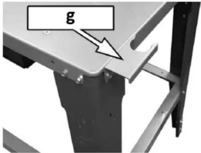
- Loosen the screws on the corner of the worktop diagonally to the corner with the switch and screw them to the top of the dust extraction hose bracket (g) - shown in the above picture with the top standing on its legs.
- Place the worktop back on its feet on a flat, stable and level surface.
- After making sure that the table is level and its legs are evenly spaced from each other, you can tighten all the screws securing them.
natural_image
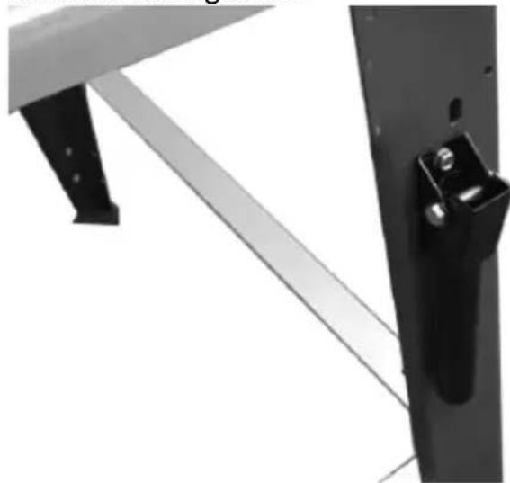
Close-up of a metal bracket with diagonal metal beams and a black handle (no text or symbols visible)- Attach the transport handles to the legs on one side of the table using screws, 2 washers and nuts.
- Press the rubber foot on the bottom of each leg.
natural_image
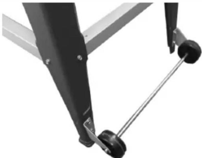
Close-up of a mechanical lever system with black and metallic components (no text or symbols visible)- Screw the axle with the transport wheels to the legs on the opposite side of the transport handles. IMPORTANT: the mounted wheels should almost touch the ground on which the unit is standing.
b) CU TTING BLADE AND BLADE GUARD
natural_image
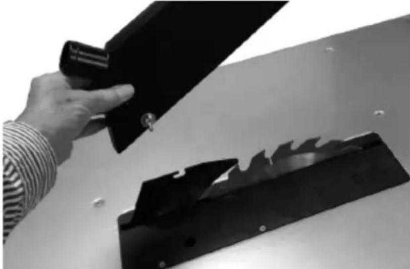
Hand holding a black clipboard next to a black metal bracket with a serrated cutout (no text or symbols visible)- With the saw blade and riving knife being pre-installed, attach the blade guard to the riving knife. IMPORTANT: for transport, the riving knife with the blade of the cutting disc is fixed in the extremely low position. Before installing the blade guard, make sure that the cutting disc is raised so that the guard does not come into contact with the blade during operation.
- C onnect the socket in the guard to the slot in the riving knife and tighten the locking screw/nut to make sure that the guard is close to the blade, but still goes up/down slightly and falls freely.
IMPORTANT: Do not use the machine without the blade guard installed. Make sure that the wing nut of the guard does not come into contact with the workpiece.
c) EXTENSION OF THE WORKTOP
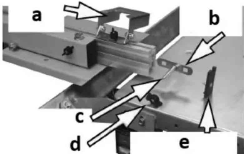
If necessary, the extension of the worktop can be mounted both on the side and on the back of the table. Depending on its location, use a short or long bracket to fix it:
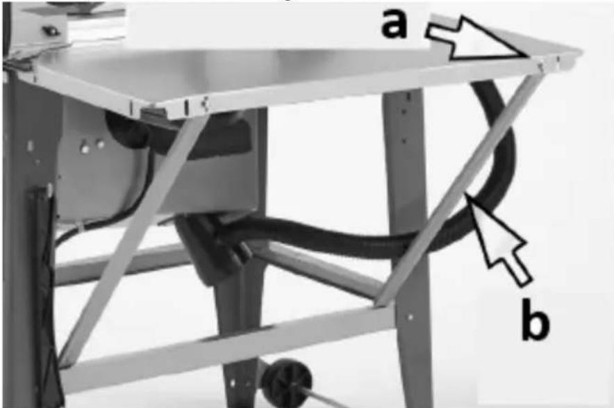
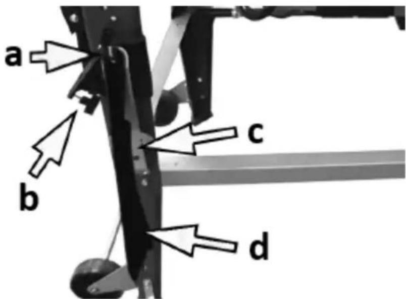
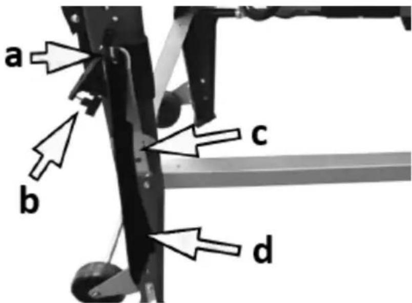
- Depending on the location of the extension of the worktop, attach it with the brackets (b) to the marked holes (a) using the attached screws, washers and nuts - do not tighten the screws yet.
- After making sure that the worktop extension is level, tighten the screws securing it.
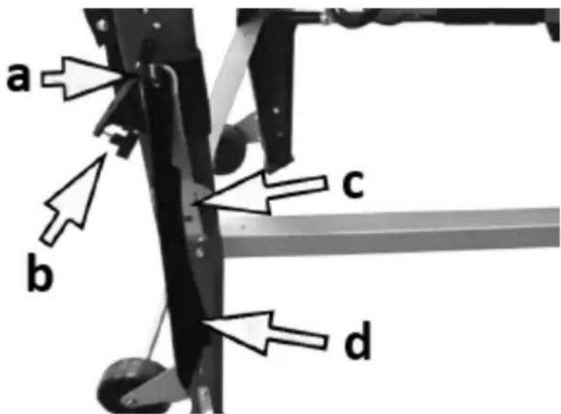
d) CONNECTING DUST REMOVING ELEMENTS
EN
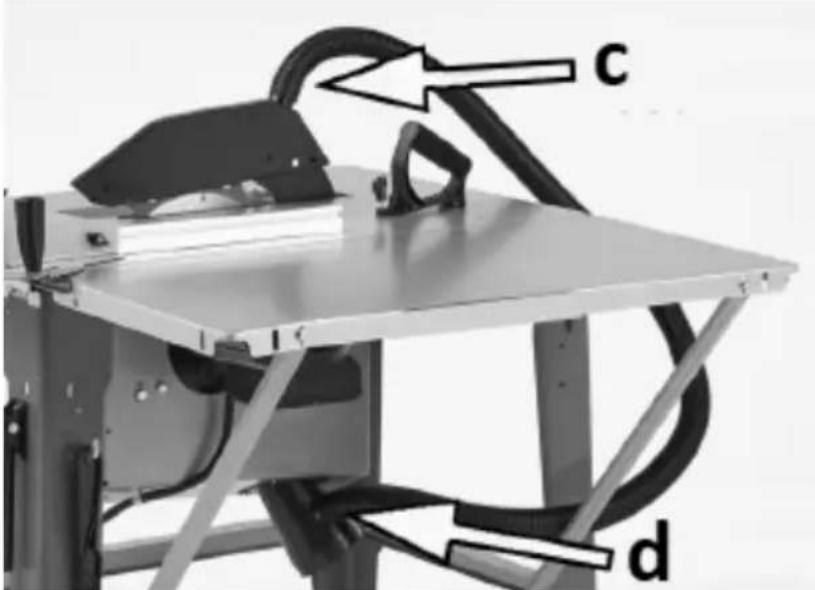
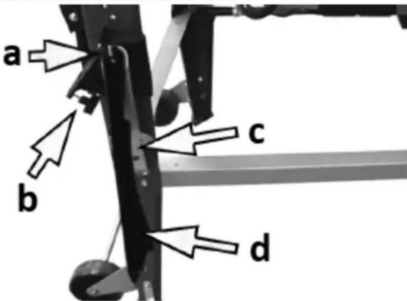
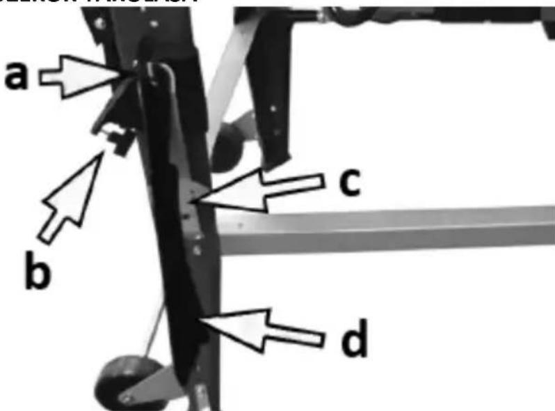
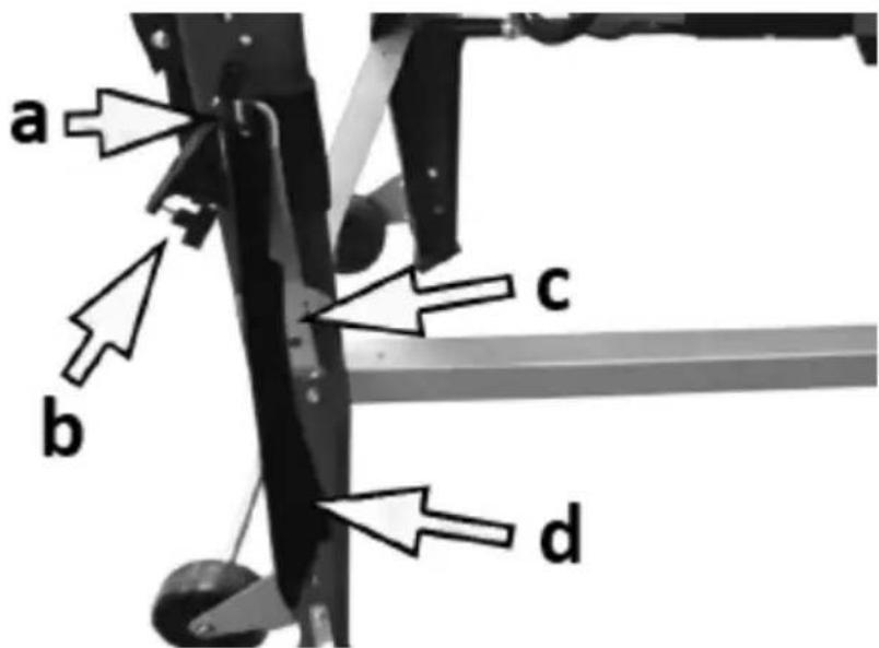
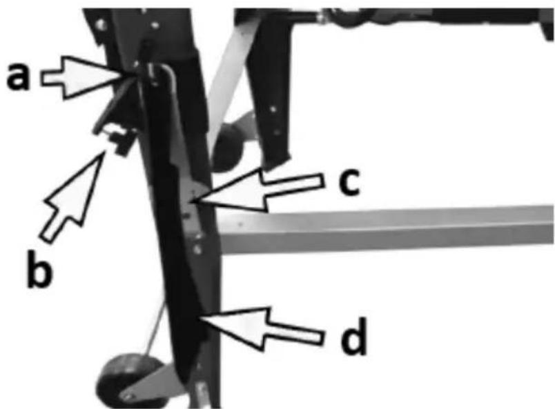
- Connect the dust extraction hose first to the blade guard (c) and the other end to the dust extraction connection at the bottom of the table (d).
- Slide the dust extraction hose into the bracket attached to the corner of the worktop.
NOTE: The use of a dust extraction system is strongly recommended and should be used whenever the machine is operating. The machine has a special outlet for connecting an external dust extraction system or an industrial vacuum cleaner. It is recommended to connect an external dust extraction source in such a way that it starts up each time the machine is started.
- A connector with a 4-inch (10 cm) adapter is required to connect an external suction system.
e) FIXING TO THE FLOOR
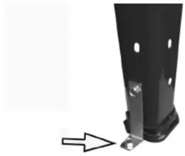
When the machine is used permanently in the same place, it can be fixed to the ground for stabilization using the attached brackets and leg screws. One bracket for each leg - arrange the mounting elements on your own.
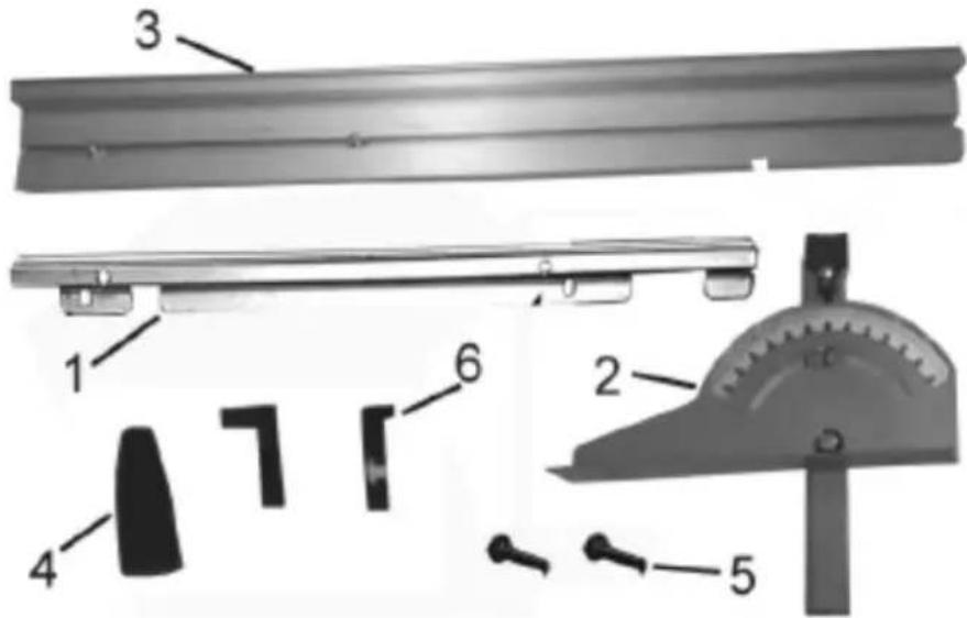
natural_image
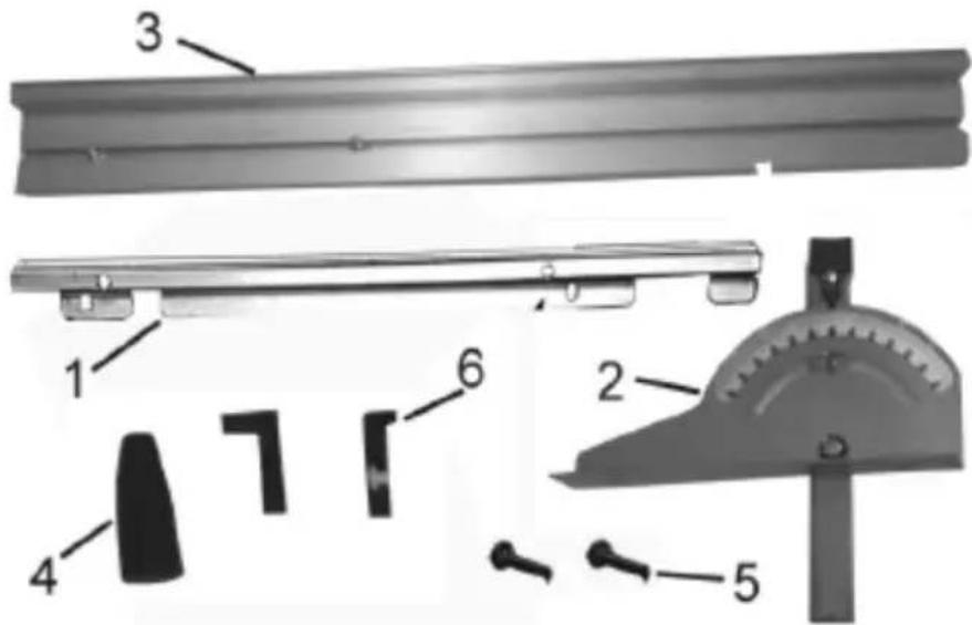
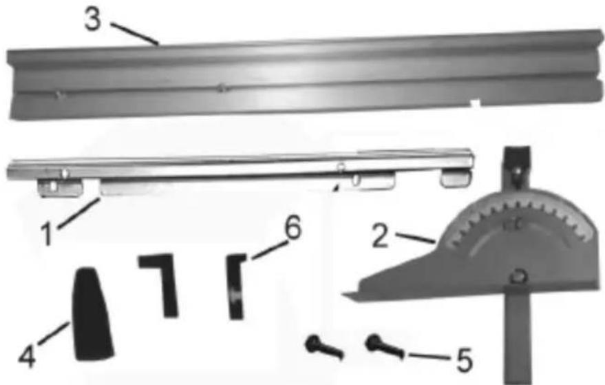
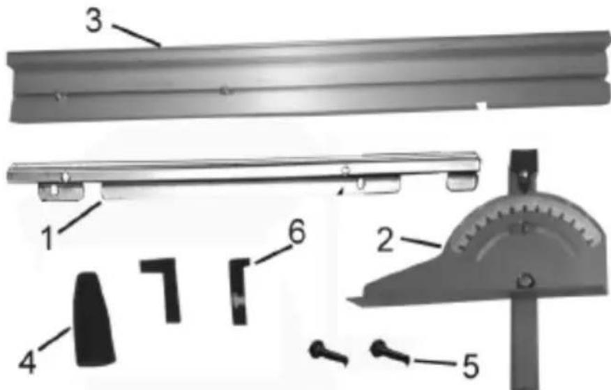
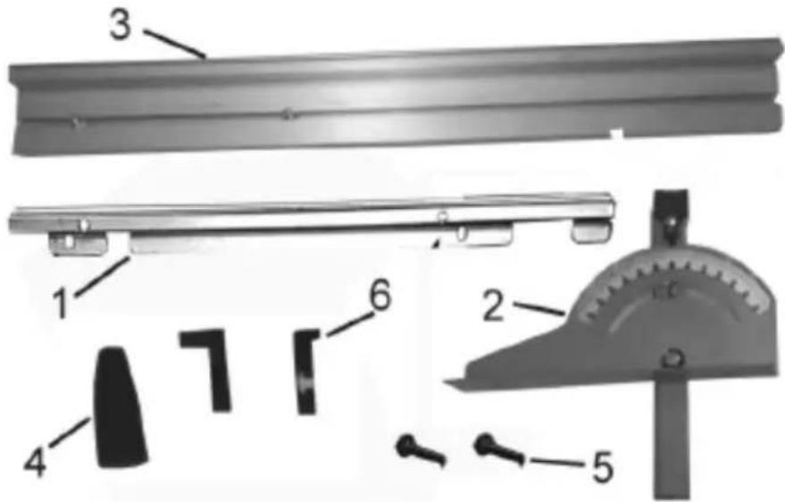
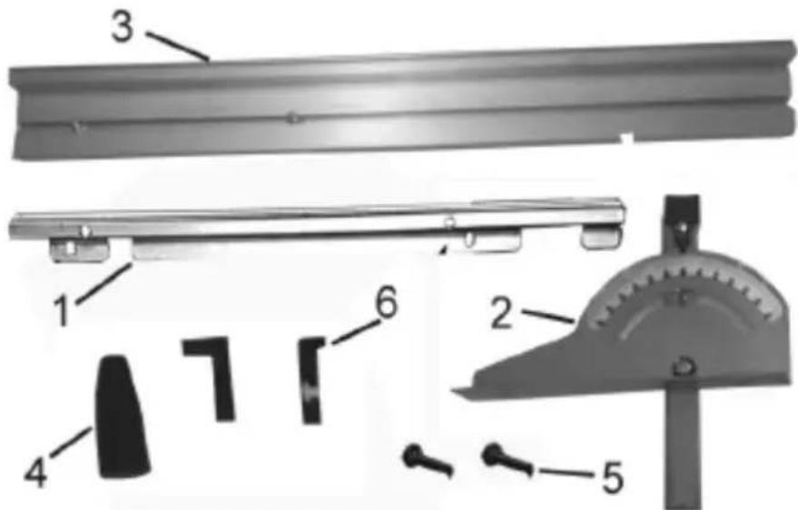
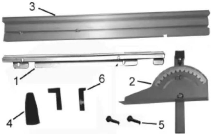
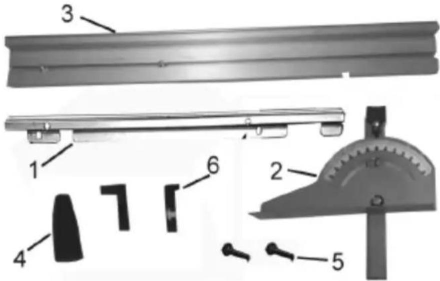
Close-up of a black metal bracket with a bolt and arrow pointing to a small component (no text or symbols visible)- S upport rail
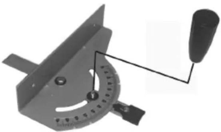
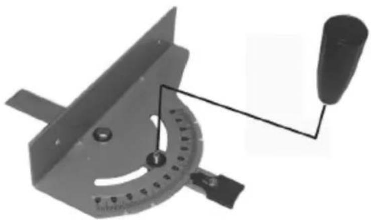
- Sl iding bar with a guide and protractor.
- Longitudinal guide
- Han dle
- Lo cking levers
- Pla stic plugs
- Attach the handle to the sliding bar with a guide and protractor using a 20 mm lock screw (see the picture above):
natural_image
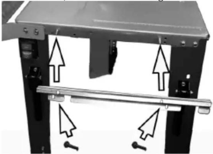
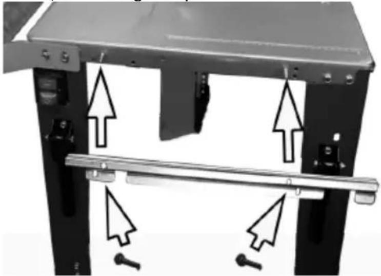
Mechanical tool with protractor and lever assembly (no text or symbols visible)- Attach the support rail to the front of the worktop with 2 M6x25 screws, 2 washers and locking levers:
natural_image
Mechanical assembly diagram showing two vertical supports with arrows indicating force directions (no text or symbols present)- Slide the longitudinal guide into the support rail and tighten the locking levers to lock it in place.
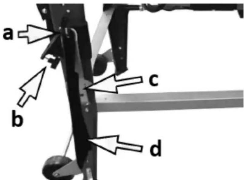
- Insert the longitudinal guide (a) into the sliding bar rail, fixing 200 mm cart bolts (b) along it. Put 2 screws through the
dedicated holes in the rail and tighten them with wing nuts
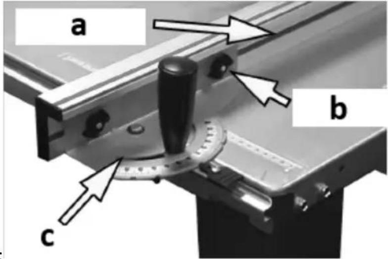
(c):
- Attach the plastic plugs to the ends of the longitudinal guide. NOTE: the longitudinal guide can be mounted vertically or on its side.
- Slide the longitudinal guide assembly into the rail and tighten the locking levers to lock it in place.
g) ASSEMBLY OF THE ANGLE GUIDE ASSEMBLY
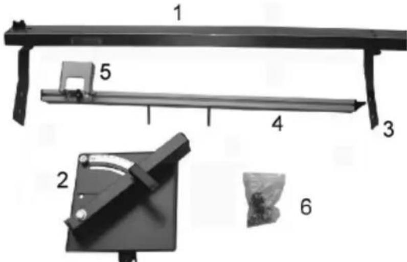
- Guide rail
- Angle adjustment element
- Bracket (x2)
- Bar
-
Foldable holding pusher
-
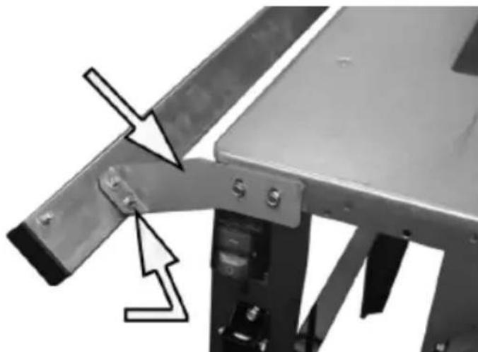
Unscrew the screws on the top of the leg and use them to attach the brackets to the left side of the table.
- Screw the guide rail to the brackets using the threaded holes on the side of the rail:
natural_image
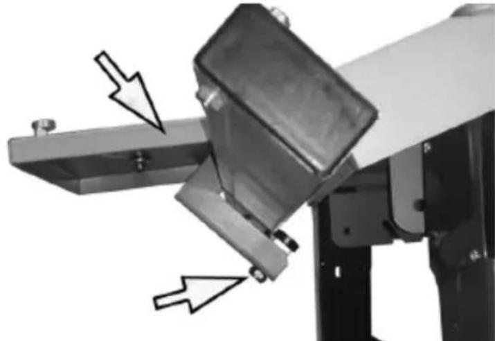
Close-up of a mechanical assembly with metal components and a directional arrow indicating movement (no text or symbols)- Insert the guide into the rail and attach it to prevent falling out by tightening the lower bearing against the guide - with a 17 mm wrench:
natural_image
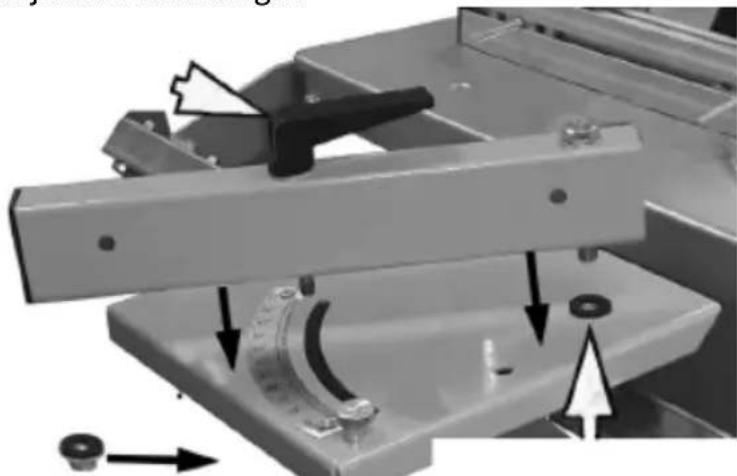
Mechanical assembly with mechanical components and directional arrows indicating motion (no text or symbols)- Slide the guide bracket into the threaded feed hole and secure it in place with a single 13mm screw. Install plastic washers between the guides and their feed cutouts and do not tighten them too tightly so that the guides can be easily adjusted at an angle.
natural_image
Mechanical assembly diagram showing a clamping mechanism with arrows indicating motion (no text or symbols)- Then attach the locking lever using the washers above and below the bracket and tighten everything from underneath with 12 mm nuts.
- Check that the guide bracket moves freely and the locking lever works smoothly:
- Slide the guide into the rail by inserting the pusher cart through the back plates that slide along the track. The screws should be put through special holes in the guide and tightened with wing nuts.
- Attach the collapsible pusher on the guide by sliding the carriage and the support plate along the rail and locking that with wing nuts.
- After installing all of these elements, attach the plastic plugs to the ends of the guide with self-tapping screws.
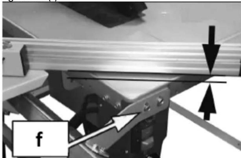
- The guide and the sliding element must be level with the worktop and only then can their assembly screws be tightened (f):
natural_image
Mechanical assembly with metallic components and directional arrows indicating motion (no text or symbols)h) STORAGE OF ACCESSORIES
EN
a. Hook for storage
b. Handle is longitudinal cuts
c. Combination wrenches
d. Pusher
- Screw the hook to the leg in a specially designed hole.
- Store the longitudinal cutter and both combination wrenches on the attached hook.
3.3. Working with the device
3.3.1 Start/Stop
- To start the machine, press the green "I" (On) button on the power switch and the cutting blade will start to rotate. IMPORTANT: Wait for a while after switching on the machine before making any cuts so that the cutting blade can reach full operating speed.
- To turn off the machine, press the "O" (Off) button on the power switch.
IMPORTANT: turn the machine off only after the workpiece has been cut. After switching off, the cutting disc will continue to run for a while.
3.3.2 Adjusting the height/angle of the blade
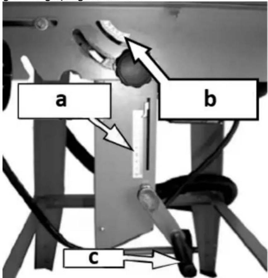
a) B lade height indicator
b) B lade tilt indicator (bevel angle)
c) Blade height adjustment knob
- To set the desired height of the blade (cutting), adjust it with the knob located at the bottom of the worktop. The scale indicates the height of the blade above the worktop.
- To adjust the angle of the blade, release the knobs that fix them at both ends of the device, then tilt the cutting disc and the drive at the desired angle - see the indicator under the worktop. Then tighten the blade angle knobs again.
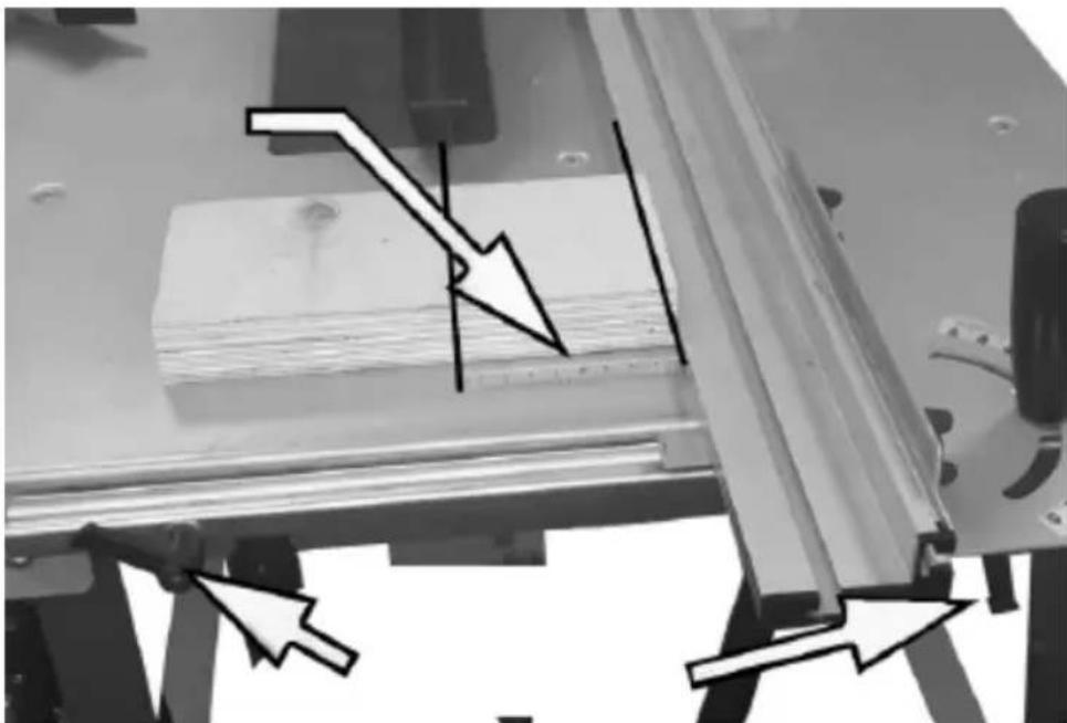
3.3.3 Adjustment of the parallel guide
natural_image
Mechanical assembly with arrows indicating force or direction of movement, no visible text or symbols- Release the levers holding the parallel guide bar and set the desired distance according to the marked scale by sliding the bar along the worktop (see the picture above).
- After setting the guide bar in the desired position, again tighten the levers.
3.3.4 Adjustment of the cross guide
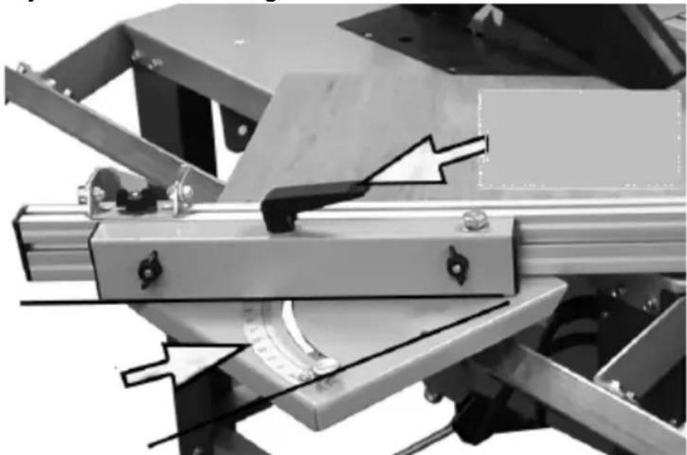
natural_image
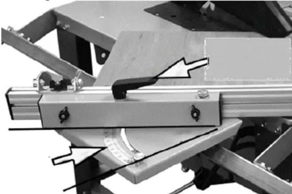
Mechanical assembly diagram showing a bracket with mounting flanges and a cylindrical component, no visible text or symbols- Loosen the lever of the cross rail and set the guide at the desired angle according to the scale (see the picture above).
- After setting the desired angle, again tighten the lever holding the guide mechanism.
- If necessary, you can dismantle the angle guide by loosening the 2 wing nuts holding it or move it in a different direction or fix it
in a lying position. They should be re-tightened after each change of position.
3.3.5 Making longitudinal cuts
natural_image
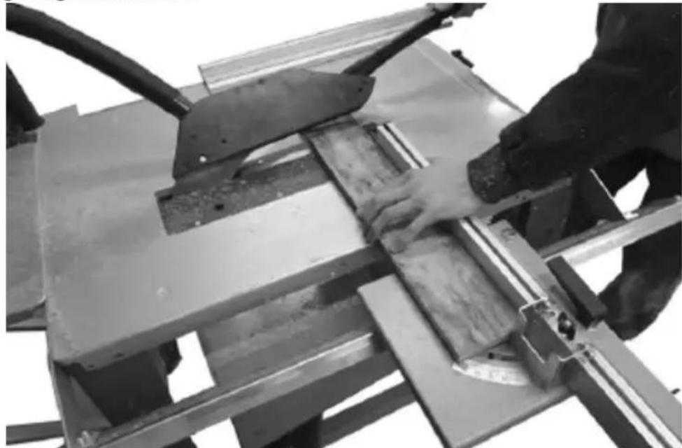
Close-up of hands operating a metal cutting machine with visible cutting tool and workpiece (no text or symbols)• AI ways use the parallel guide when making such cuts.
- After turning on the machine and waiting for the cutting blade to reach its working speed, place the element to be cut on the worktop and then slowly push it by hand along the parallel guide towards the blade, but not further than into the blade guard.
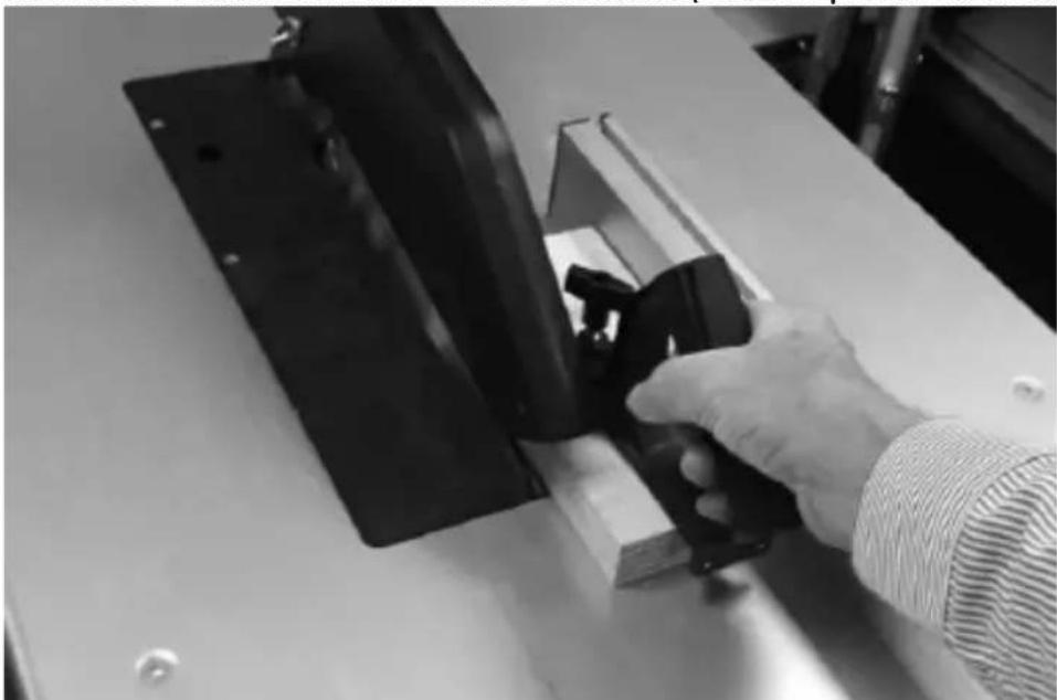
- Use the attached pusher or - especially for small parts - a special handle to cut the remains of the element (see the picture below):
natural_image
Person in gloves operating a mechanical clamp or fixture on a workbench (no visible text or symbols)- A lways push the workpiece to the cut is done, i.e. when it is fully cut.
• T o cut larger elements, you can use the extension of the worktop.
- Use the same procedure for cutting with the blade at an angle. If you need to make a precise cut, you can additionally use a protractor between the blade and the worktop.
3.3.6 Cutting small/narrow workpieces
natural_image
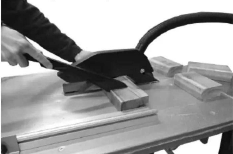
Person using a lathe machine to cut metal blocks on a workbench (no text or symbols visible)- For cutting small/narrow objects, use the included pusher, which keeps the operator's hand at a safe distance from the blade.
3.3.7 Cross cutting
natural_image
Mechanical assembly with metal components and a curved pipe fitting (no visible text or symbols)- When making cross cuts, use the holding pusher and move the element to be cut along the set cross guide.
- Always hold the part of the object to be cut, never the part that will be cut off.
3.4. Cleaning and maintenance
a) Pull the mains plug and let the unit cool down completely before cleaning, adjusting or replacing accessories and when the unit is not in use.
- Wait until the rotating parts stop.
b) Only cleaners that do not contain corrosive substances should be used to clean plastic parts.
c) After each cleaning, all the parts should be dried well before the unit is used again.
d) Store the unit in a dry and cool place protected from moisture and direct sunlight.
e) Do not spray the unit with a stream of water or immerse it in water.
f) Make sure that no water enters through the ventilation openings in the casing.
g) Clean the ventilation openings with a brush and compressed air.
h) Perform regular inspections of the unit checking technical fitness and any damages.
i) Use a soft cloth for cleaning.
j) Do not use sharp and/or metal objects (e.g. wire brush or metal spatula) for cleaning as they may damage the surface of the appliance material.
3.4.1 Replacing the cutting disc
NOTE: when removing the cutting disc, it is recommended to use protective gloves for the blade.
- Remove the entire blade guard, i.e. cover and cover insert fastened to the worktop:
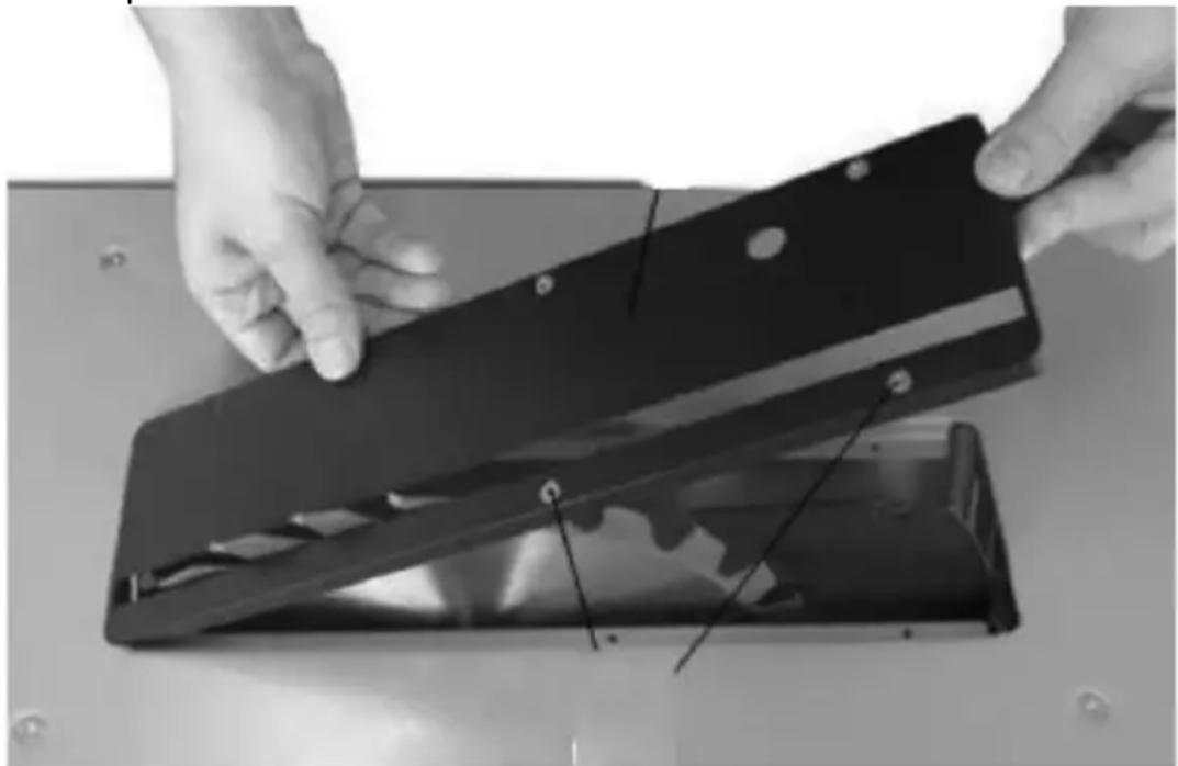
natural_image
Close-up of hands installing or adjusting a black plastic cover on a metal surface (no text or symbols visible)- Use the blade height adjustment lever to raise the blade as far as it will go.
- Using two combination wrenches, lock the engine and loosen the nut holding the cutting disc (standard right-hand thread):
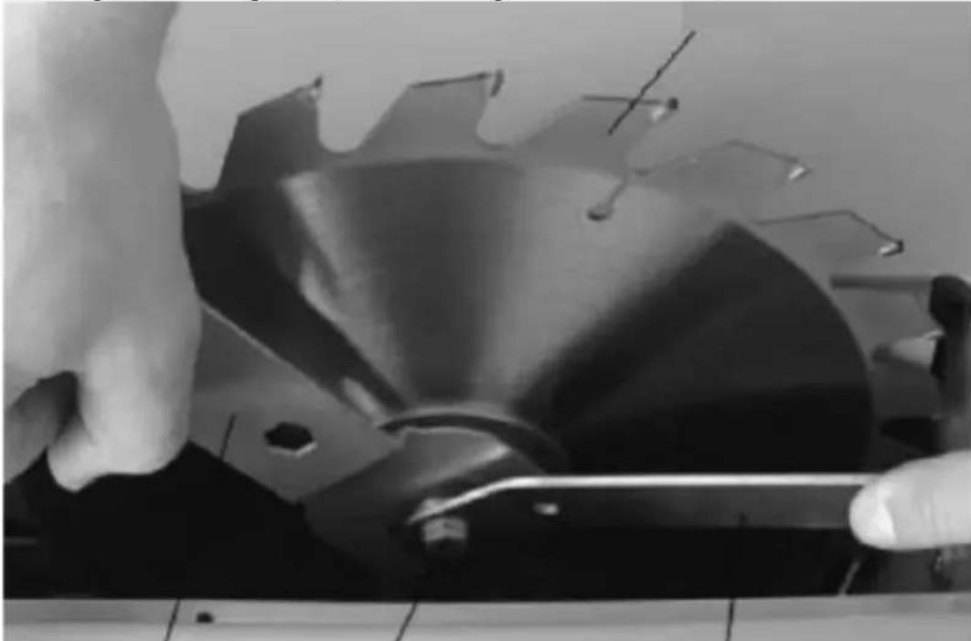
natural_image
Close-up of hands operating a mechanical device with a circular component and tools (no visible text or symbols)- D ismantle the cutting disc clamping ring and then the disc itself by removing it from the motor spindle and then carefully lifting it up.
• In stall the new blade in the reverse order of removal.
IMPORTANT: the space between the blade guard and the blade itself should be 2-5 mm:
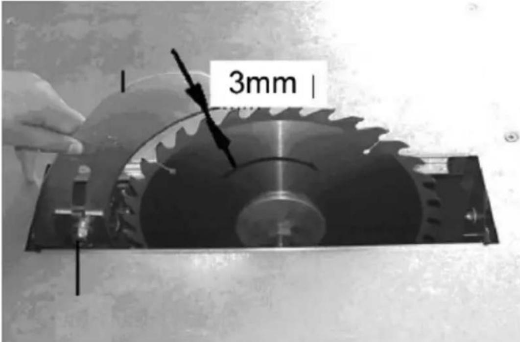
- Check the correctness of assembly of all components of the device - also by briefly starting the machine "on empty".
NOTE: Use only cutting discs that meet the required standards (EN847-1).
DISPOSAL OF WASTE APPLIANCES
At the end of its useful life, this product should not be disposed of with normal household waste but should be taken to a collection point for the recycling of electrical and electronic equipment. This is indicated by the symbol on the product, operating instructions, or packaging. The materials used in this appliance are recyclable according to their marking. By reusing, recycling, or applying other forms of use of waste machines, you make a significant contribution to the protection of our environment.
Your local administration will provide you with information about the appropriate disposal point for used appliances.
TROUBLESHOOTING
| Problem | Possible cause | Action |
| The machine does not start | a. Power plug not connectedb. Blown fusec. Defective power cord | a. Connect the machine to electricityb. Replace the blown fusec. Replace the power cord (by a qualified person/service provider) |
| It is impossible to make precise cuts at an angle of 45° and 90° | The worktop is not level or the tilt angle indicator is misaligned | First level the worktop with a spirit level, then adjust the cutting disc and check its angle |
| The material being cut is blocking the blade | The cut element is not evenly attached to the guide, the wood is warped or the edge of the blade is not at a right angle to the element | Check and correct the guide or blade or change the piece of wood that is being cut |
| The material being cut is blocking the riving knife | The blade is not properly aligned | Check that the riving knife is fitted in line with the blade |
| The saw cuts crookedly, unevenly, the cuts are imprecise | a. Dull bladeb. The cutting disc is mounted the other way roundc. Dirty bladed. Wrong blade selectione. Dirty worktop that prevents the correct | a. Replace the cutting discsb. Attach the cutting disc correctlyc. Clean and degrease the bladed. Change the blade to the one dedicated to the task |
EN
| supply of the element to be cut | e. Clean the worktop - for a better, smooth surface, it can be waxed | |
| The material being cut is thrown away from the blade | a. Unevenly clamped riving knifeb. The riving knife is not in line with the bladec. No riving knife is attachedd. The cut element is released too early by the operator, as a result of which it is not completely cute. Blade is worn out | a. Align the riving knifeb. Install and align the riving knife to the bladec. Attach the riving knifed. Improve the technique of working with the cut elemente. Replace the cutting disc |
| The cutting disc cannot be tilted smoothly | Dirty tilt mechanism from clippings | Clean the tilting mechanism |
| The blade does not accelerate to operating speed | Extension cable too long | Use a shorter extension cable |
| The machine vibrates strongly | a. The machine is not standing steadily on the surface.b. Damaged cutting disc. | a. Level the machine or place it in another, level placeb. Replace defective cutting disc |

natural_image
Close-up of a mechanical assembly with visible wiring and a labeled component 'f' (no text or symbols beyond label)natural_image
Close-up of a metal bracket with diagonal metal beams and a black clip (no text or symbols visible)natural_image
Close-up of a mechanical lever system with black and metallic components (no text or symbols visible)natural_image
Hand holding a black clipboard next to a black metal bracket with a serrated cutout (no text or symbols visible)natural_image
Mechanical device with labeled parts (c and d) showing internal components and wiring (no readable text or symbols beyond labels)natural_image
Close-up of a black corrugated cable or hose attached to a metal frame (no text or symbols visible)natural_image
Close-up of a black metal bracket with a bolt and arrow pointing to a small component (no text or symbols visible)f) MONTAŻ ZESPOŁU PROWADNICY WZDŁUŻNEJ
natural_image
Mechanical tool with protractor and lever assembly (no text or symbols visible)natural_image
Mechanical assembly diagram showing two vertical supports with arrows indicating force directions (no text or symbols)natural_image
Close-up of a mechanical assembly with a metallic bracket and mounting holes, showing a directional arrow (no text or symbols)natural_image
Mechanical assembly with directional arrows indicating movement or force (no text or symbols)natural_image
Mechanical assembly diagram showing a clamp mechanism with directional arrows and a curved component (no text or symbols)natural_image
Mechanical assembly with metallic components and directional arrows indicating motion (no text or symbols)h) PRZECHOWYWANIE AKCESORIÓW
natural_image
Mechanical assembly with arrows indicating direction of motion or force, no visible text or symbolsnatural_image
Mechanical assembly diagram showing a bracket with mounting flanges and a cylindrical component, no visible text or symbolsnatural_image
Close-up of hands operating a metal cutting machine with visible cutting tools and work (no text or symbols)natural_image
Person in gloves handling a black mechanical component on a workbench (no visible text or symbols)natural_image
Person using a saw to cut wood blocks on a metal workbench, with no visible text or symbolsnatural_image
Mechanical assembly diagram showing a clamping mechanism with metal components and directional arrows (no text or symbols)natural_image
Close-up of hands installing or adjusting a black plastic cover on a metal tray (no text or symbols visible)natural_image
Close-up of hands operating a mechanical component with a tool, no visible text or symbolsnatural_image
Close-up of a metal bracket with diagonal metal beams and a black clip, no visible text or symbolsnatural_image
Close-up of a mechanical lever system with black and metallic components (no text or symbols visible)natural_image
Hand holding a black clipboard next to a black metal bracket with a serrated cutout (no text or symbols visible)natural_image
Close-up of a black corrugated cable attached to a metal frame structure (no text or symbols visible)natural_image
Close-up of a black metal bracket with a small bolt and arrow pointing to its side (no text or symbols visible)f) MONTÁŽ PODÉLNÝCH VODÍTEK MONTÁŽ
natural_image
Mechanical device with a protractor and lever, no visible text or symbolsnatural_image
Mechanical assembly diagram showing two vertical supports with arrows indicating force directions (no text or symbols present)natural_image
Close-up of a mechanical assembly with metal components and a directional arrow indicating movement (no text or symbols)natural_image
Mechanical assembly with metal components and directional arrows indicating movement (no text or symbols)natural_image
Mechanical assembly diagram showing a clamping mechanism with arrows indicating motion (no text or symbols)natural_image
Mechanical assembly with metallic components and directional arrows indicating motion (no text or symbols)h) SKLADOVÁNÍ PŘÍSLUŠENSTVÍ
natural_image
Mechanical assembly with arrows indicating force or direction of movement, no visible text or symbolsnatural_image
Mechanical assembly diagram showing a bracket with mounting flanges and a cylindrical component, no visible text or symbolsnatural_image
Close-up of hands operating a metal cutting machine with visible cutting tools and components (no text or symbols)natural_image
Person in gloves operating a mechanical device with a black bracket and metal frame (no visible text or symbols)natural_image
Close-up of hands installing or adjusting a black metal component on a workbench (no visible text or symbols)natural_image
Close-up of hands operating a mechanical component with a tool, no visible text or symbolsnatural_image
Close-up of a mechanical assembly with a black component and wiring, no visible text or symbolsnatural_image
Close-up of a metal bracket with diagonal support and a close-up of the handle (no text or symbols visible)natural_image
Close-up of a mechanical lever system with black and metallic components (no text or symbols visible)natural_image
Hand holding a black clipboard next to a black metal bracket with a serrated cutout (no text or symbols visible)natural_image
Mechanical device with labeled parts (c and d) showing internal components and wiring (no readable text or symbols beyond labels)natural_image
Close-up of a black corrugated cable being inserted into a mechanical bracket (no text or symbols visible)natural_image
Close-up of a black metal bracket with a bolt and arrow pointing to a small component (no text or symbols visible)f) ASSEMBLAGE DE L'ENSEMBLE DE GUIDAGE LONGITUDINAL
natural_image
Mechanical tool with protractor and lever assembly (no text or symbols visible)natural_image
Mechanical assembly diagram showing two vertical supports with arrows indicating force directions (no text or symbols present)natural_image
Close-up of a mechanical assembly with metal components and a directional arrow indicating movement (no text or symbols)natural_image
Mechanical assembly with directional arrows indicating movement or force (no text or symbols)natural_image
Mechanical assembly diagram showing a cutting machine with mounting holes and directional arrows indicating motion (no text or symbols)natural_image
Close-up of a mechanical assembly with metallic components and directional arrows indicating force or movement (no text or symbols)FR
h) STOCKAGE DES ACCESSOIRES
natural_image
Mechanical assembly with arrows indicating direction of motion or force, no visible text or symbolsnatural_image
Mechanical assembly diagram showing a bracket with mounting flanges and a curved pipe, no visible text or symbolsnatural_image
Close-up of hands operating a metal cutting machine with visible cutting tools and work materials (no text or symbols)natural_image
Person in gloves handling a black mechanical component on a workbench (no visible text or symbols)natural_image
Person using a tool to cut or spread material on a metal workbench, no visible text or symbolsnatural_image
Mechanical assembly diagram showing a clamping mechanism with no visible text or symbolsnatural_image
Close-up of hands installing or adjusting a black plastic cover on a metal tray (no text or symbols visible)natural_image
Close-up of hands operating a mechanical device with a tool, no visible text or symbolsnatural_image
Close-up of a mechanical assembly with a black component and wiring, no visible text or symbolsnatural_image
Close-up of a metal bracket with diagonal bracing and mounting feet (no text or symbols visible)natural_image
Close-up of a mechanical lever system with black and metallic components (no text or symbols visible)natural_image
Hand holding a black clipboard next to a black metal bracket with a serrated cutout (no text or symbols visible)natural_image
Close-up of a black corrugated cable being inserted into a metal frame (no text or symbols visible)natural_image
Close-up of a black metal bracket with a bolt and arrow pointing to its side (no text or symbols visible)natural_image
Mechanical tool with protractor and lever assembly (no text or symbols visible)natural_image
Mechanical assembly diagram showing two vertical supports with arrows indicating force directions (no text or symbols)natural_image
Close-up of a mechanical assembly with metal components and a directional arrow indicating movement (no text or symbols)natural_image
Mechanical assembly with mechanical components and directional arrows indicating motion (no text or symbols)natural_image
Mechanical assembly diagram showing a clamping mechanism with arrows indicating motion (no text or symbols)natural_image
Mechanical assembly with a metallic rod and directional arrows indicating force or movement (no text or symbols)natural_image
Mechanical assembly with arrows indicating direction of motion or force, no visible text or symbolsnatural_image
Mechanical assembly diagram showing a bracket with mounting flanges and a cylindrical component, no visible text or symbolsnatural_image
Close-up of hands operating a metal cutting machine with metal framing (no visible text or symbols)natural_image
Person in gloves operating a mechanical device on a workbench (no visible text or symbols)natural_image
Person using a tool to cut or spread material on a metal workbench, no visible text or symbolsnatural_image
Mechanical assembly diagram showing a clamping mechanism with no visible text or symbolsES
natural_image
Close-up of a mechanical assembly with a black component and wiring, no visible text or symbolsnatural_image
Close-up of a metal bracket with a diagonal support and handle (no text or symbols visible)natural_image
Close-up of a mechanical lever system with black and metallic components (no text or symbols visible)natural_image
Hand holding a black clipboard next to a black metal bracket with a serrated cutout (no text or symbols visible)natural_image
Close-up of a black corrugated cable being inserted into a mechanical bracket (no text or symbols visible)natural_image
Close-up of a black metal bracket with a bolt and mounting holes, pointing to a small arrow (no text or symbols visible)natural_image
Mechanical tool with protractor and lever assembly (no text or symbols visible)natural_image
Mechanical assembly diagram showing two vertical supports with arrows indicating force directions (no text or symbols present)natural_image
Close-up of a mechanical assembly with metal components and a directional arrow indicating movement (no text or symbols)natural_image
Mechanical assembly with directional arrows indicating movement or force (no text or symbols)natural_image
Mechanical assembly diagram showing a clamping mechanism with arrows indicating motion (no text or symbols)natural_image
Close-up of a mechanical component with arrows indicating force or movement, no visible text or symbolsh) ALMACENAMIENTO DE ACCESORIOS
natural_image
Mechanical assembly with arrows indicating force or direction of movement, no visible text or symbolsnatural_image
Mechanical assembly diagram showing a bracket with mounting flanges and a cylindrical component, no visible text or symbolsnatural_image
Close-up of hands operating a metal cutting machine with visible cutting tools and components (no text or symbols)natural_image
Person in gloves handling a black mechanical component on a workbench (no visible text or symbols)natural_image
Person using a lathe machine to cut wooden blocks on a workbench (no text or symbols visible)natural_image
Mechanical assembly diagram showing a clamping mechanism with no visible text or symbolsnatural_image
Close-up of hands installing or adjusting a black metal component on a workbench (no visible text or symbols)natural_image
Close-up of hands operating a mechanical component with a circular blade and flange (no visible text or symbols)natural_image
Close-up of a mechanical assembly with a black component and wiring, no visible text or symbolsnatural_image
Close-up of a metal bracket with diagonal metal beams and a black handle (no text or symbols visible)natural_image
Close-up of a mechanical lever system with black and metallic components (no text or symbols visible)natural_image
Hand holding a black clipboard next to a black metal bracket with a serrated cutout (no text or symbols visible)natural_image
3D printer or scanner device with labeled parts (c and d) and cable routing (no readable text or symbols beyond labels)natural_image
Close-up of a black corrugated cable being inserted into a mechanical bracket (no text or symbols visible)natural_image
Close-up of a black metal bracket with a bolt and mounting holes, pointing to a small arrow (no text or symbols visible)natural_image
Mechanical tool with protractor and lever assembly (no text or symbols visible)natural_image
Mechanical assembly diagram showing two vertical supports with arrows indicating force directions (no text or symbols present)natural_image
Close-up of a mechanical assembly with arrows indicating force or movement (no visible text or symbols)natural_image
Mechanical assembly with directional arrows indicating movement or force (no text or symbols visible)natural_image
Mechanical assembly diagram showing a clamping mechanism with arrows indicating motion (no text or symbols)natural_image
Mechanical assembly with metallic components and directional arrows indicating motion (no text or symbols)h) TARTOZÉKOK TÁROLÁSA
natural_image
Mechanical assembly with arrows indicating force or direction of movement, no visible text or symbolsnatural_image
Mechanical assembly diagram showing a bracket with mounting flanges and a cylindrical component, no visible text or symbolsnatural_image
Close-up of hands operating a metal cutting machine with visible cutting tools and work components (no text or symbols)natural_image
Person in gloves operating a mechanical device with a black component on a workbench (no visible text or symbols)natural_image
Person using a cutting tool on a wooden cutting board, no visible text or symbolsnatural_image
Mechanical assembly diagram showing a bracket with mounting flanges and a tool, no visible text or symbolsnatural_image
Close-up of hands installing or adjusting a black metal component on a workbench (no visible text or symbols)natural_image
Close-up of hands operating a mechanical component with a tool, no visible text or symbolsnatural_image
Close-up of a mechanical assembly with visible wiring and a labeled component 'f' (no text or symbols beyond label)natural_image
Close-up of a metal bracket with diagonal metal beams and a black handle (no text or symbols visible)natural_image
Close-up of a mechanical lever system with black and metallic components (no text or symbols visible)- Skru akslen med transporthjulene fast på benene på den modsatte side af transporthåndtagene.
natural_image
Hand holding a black clipboard next to a black metal bracket with a serrated cutout (no text or symbols visible)natural_image
Close-up of a black flexible hose attached to a metal frame, no visible text or symbolsnatural_image
Close-up of a black metal bracket with a small bolt and arrow pointing to its side (no text or symbols visible)f) SAMLING AF LANGSGÅENDE STYREENHED
natural_image
Mechanical tool with protractor and lever assembly (no text or symbols visible)natural_image
Mechanical assembly diagram showing two vertical supports with directional arrows indicating movement or force (no text or symbols present)natural_image
Close-up of a mechanical assembly with metal components and a directional arrow indicating movement (no text or symbols)natural_image
Mechanical assembly with mechanical components and directional arrows indicating motion (no text or symbols)natural_image
Mechanical assembly diagram showing a clamping mechanism with arrows indicating motion (no text or symbols)natural_image
Close-up of a mechanical component with arrows indicating force or movement, no visible text or symbolsh) OPBEVARING AF TILBEH∅R
natural_image
Mechanical assembly with arrows indicating force or direction of movement, no visible text or symbolsnatural_image
Mechanical assembly diagram showing a bracket with mounting flanges and a cylindrical component, no visible text or symbolsnatural_image
Close-up of hands operating a metal cutting machine with visible cutting tools and work components (no text or symbols)natural_image
Person in gloves operating a mechanical clamp or fixture on a workbench (no visible text or symbols)natural_image
Person using a cutting tool on a wooden cutting board, no visible text or symbolsnatural_image
Mechanical assembly diagram showing a bracket with mounting flanges and a tool, no visible text or symbolsnatural_image
Close-up of hands installing or adjusting a black metal component on a workbench (no visible text or symbols)natural_image
Close-up of hands operating a mechanical component with visible cutting edge and base (no text or symbols)natural_image
Close-up of a mechanical assembly with a black component and wiring, no visible text or symbolsnatural_image
Close-up of a metal bracket with diagonal metal strip and mounting bracket (no text or symbols visible)natural_image
Close-up of a mechanical lever system with black and metallic components (no text or symbols visible)natural_image
Person handling a black plastic clip attached to a metal plate, with no visible text or symbolsnatural_image
Close-up of a black metal bracket with a small bolt and arrow pointing to its side (no text or symbols visible)natural_image
Mechanical tool with protractor and lever assembly (no text or symbols visible)natural_image
Mechanical assembly diagram showing two vertical supports with arrows indicating force directions (no text or symbols)natural_image
Close-up of a mechanical assembly with metal components and a directional arrow indicating movement (no text or symbols)natural_image
Mechanical assembly with mechanical components and directional arrows indicating motion (no text or symbols)natural_image
Mechanical assembly diagram showing a clamping mechanism with arrows indicating motion (no text or symbols)natural_image
Mechanical assembly with metallic components and directional arrows indicating motion (no text or symbols)h) LISÄVARUSTEIDEN SÄILYTYS
natural_image
Mechanical assembly with arrows indicating force or direction of movement, no visible text or symbolsnatural_image
Mechanical assembly diagram showing a bracket with mounting flanges and a cylindrical component, no visible text or symbolsnatural_image
Close-up of hands operating a metal cutting machine with visible cutting tools and work (no text or symbols)natural_image
Person in gloves operating a mechanical device with a black bracket and metal frame (no visible text or symbols)natural_image
Person using a lathe machine to cut wooden blocks on a workbench (no text or symbols visible)natural_image
Mechanical assembly with metal components and a cylindrical component (no visible text or symbols)natural_image
Close-up of hands installing or adjusting a black metal component on a workbench (no visible text or symbols)natural_image
Close-up of hands operating a mechanical component with visible cutting edge and base (no text or symbols)3.2.2 PLAATSING VAN HET APPARAAT
natural_image
Close-up of a mechanical assembly with visible wiring and a labeled component 'f' (no text or symbols beyond label)natural_image
Close-up of a metal bracket with diagonal metal strip and mounting bracket (no text or symbols visible)natural_image
Close-up of a mechanical lever system with black and metallic components (no text or symbols visible)natural_image
Hand holding a black clipboard next to a black metal bracket with a serrated cutout (no text or symbols visible)natural_image
3D printer or scanner device with labeled parts (c and d) and cable routing (no readable text or symbols beyond labels)natural_image
Close-up of a black corrugated cable inserted into a mechanical bracket (no text or symbols visible)natural_image
Close-up of a black metal bracket with a bolt and mounting holes, pointing to a small arrow (no text or symbols visible)f) MONTAGE VAN DE LONGITUDINALE GELEIDING
natural_image
Mechanical tool with protractor and lever assembly (no text or symbols visible)natural_image
Mechanical assembly diagram showing two vertical supports with arrows indicating force directions (no text or symbols)natural_image
Close-up of a mechanical assembly with metal components and a directional arrow indicating movement (no text or symbols)natural_image
Mechanical assembly with directional arrows indicating movement or force (no text or symbols)natural_image
Mechanical assembly diagram showing a clamp mechanism with directional arrows and a circular component (no text or symbols)natural_image
Mechanical assembly with metallic components and directional arrows indicating motion (no text or symbols)natural_image
Mechanical assembly with arrows indicating force or direction of movement, no visible text or symbolsnatural_image
Mechanical assembly diagram showing a mechanical component with mounting brackets and alignment arrows (no text or symbols)natural_image
Close-up of hands operating a metal cutting machine with visible cutting edge and workpiece (no text or symbols)natural_image
Person in gloves handling a black mechanical component on a workbench (no visible text or symbols)natural_image
Person using a tool to cut or spread material on a metal workbench, no visible text or symbolsnatural_image
Mechanical assembly diagram showing a clamping mechanism with no visible text or symbolsnatural_image
Close-up of hands installing or adjusting a black plastic cover on a metal tray (no text or symbols visible)natural_image
Close-up of hands operating a mechanical component with a tool, no visible text or symbolsnatural_image
Close-up of a mechanical assembly with a button and cable, no visible text or symbolsnatural_image
Close-up of a metal bracket with diagonal support and mounting bracket (no text or symbols visible)natural_image
Close-up of a mechanical lever system with black and metallic components (no text or symbols visible)natural_image
Person handling a black plastic clip attached to a metal bracket (no text or symbols visible)- Mens sagbladet og spaltekniven er forhåndsinstallert, fester du bladbeskyttelsen til spaltekniven.
natural_image
Close-up of a black corrugated cable being inserted into a mechanical frame (no text or symbols visible)- En kontakt med en 4-tommers (10 cm) adapter kreves for å koble til et eksternt sugesystem.
e) FESTE TIL GULV
natural_image
Close-up of a black metal bracket with a bolt and mounting bracket, showing a small arrow pointing to the end (no text or symbols present)f) MONTERING AV LENGDEGUIDEMONTERING
- Støtteskinne
- Skyvestang med guide og gradskive.
- Langsgående guide
- Håndtak
- Låsespaker
- Plastplugger
- Fest håndtaket til glidestangen med en guide og gradskive ved hjelp av en 20 mm låseskrue (se bildet over):
natural_image
Mechanical tool with measurement scale and pointer (no text or symbols visible)- Fest støtteskinnen foran på benkeplaten med 2 M6x25 skruer, 2 skiver og låsespaker:
natural_image
Mechanical assembly diagram showing two vertical supports with arrows indicating force directions (no text or symbols present)natural_image
Close-up of a mechanical assembly with metal components and a directional arrow indicating movement (no text or symbols)natural_image
Mechanical assembly with mechanical components and directional arrows indicating motion (no text or symbols)natural_image
Mechanical assembly diagram showing a clamping mechanism with arrows indicating motion (no text or symbols)natural_image
Close-up of a mechanical assembly with metallic components and directional arrows indicating motion (no text or symbols)h) OPPBEVARING AV TILBEH∅R
natural_image
Mechanical assembly with arrows indicating force or direction of movement, no visible text or symbolsnatural_image
Mechanical assembly diagram showing a rotating component with arrows indicating motion direction (no text or symbols)natural_image
Close-up of hands operating a metal cutting machine with visible cutting tools and components (no text or symbols)natural_image
Person in gloves handling a black mechanical component on a workbench (no visible text or symbols)natural_image
Person using a lathe machine to cut metal blocks on a workbench (no text or symbols visible)natural_image
Mechanical assembly diagram showing a bracket with mounting holes and a tool, no visible text or symbolsnatural_image
Close-up of hands installing or adjusting a black metal component on a workbench (no visible text or symbols)natural_image
Close-up of hands operating a mechanical component with visible cutting edge and base (no text or symbols)natural_image
Close-up of a mechanical assembly with a black component and wiring, no visible text or symbolsnatural_image
Close-up of a metal bracket with diagonal metal beams and a black clip, no visible text or symbolsnatural_image
Close-up of a mechanical lever system with black and metallic components (no text or symbols visible)natural_image
Person handling a black plastic clip attached to a metal plate, with no visible text or symbolsnatural_image
Close-up of a black corrugated cable being inserted into a mechanical bracket (no text or symbols visible)natural_image
Close-up of a black metal bracket with a small bolt and arrow pointing to its side (no text or symbols visible)f) MONTERING AV LÄNGDGUIDEMONTERING
natural_image
Mechanical tool with measurement scale and pointer (no text or symbols visible)natural_image
Mechanical assembly diagram showing two vertical supports with directional arrows indicating movement or force (no text or symbols present)natural_image
Close-up of a mechanical assembly with metal components and a directional arrow indicating movement (no text or symbols)natural_image
Mechanical assembly with mechanical components and directional arrows indicating motion (no text or symbols)natural_image
Mechanical assembly diagram showing a clamping mechanism with arrows indicating motion (no text or symbols)natural_image
Mechanical assembly with metallic components and directional arrows indicating motion (no text or symbols)h) FÖRVARING AV TILLBEHÖR
natural_image
Mechanical assembly with arrows indicating force or direction of movement, no visible text or symbolsnatural_image
Mechanical assembly diagram showing a rotating component with arrows indicating motion direction (no text or symbols)natural_image
Close-up of hands operating a metal cutting machine with visible cutting tools and components (no text or symbols)natural_image
Person in gloves handling a black metal clamp on a workbench (no visible text or symbols)natural_image
Person using a lathe machine to cut metal blocks on a workbench (no text or symbols visible)natural_image
Mechanical assembly diagram showing a bracket with mounting holes and a tool, no visible text or symbolsnatural_image
Close-up of hands installing or adjusting a black metal component on a workbench (no visible text or symbols)natural_image
Close-up of hands operating a mechanical component with visible cutting edge and base (no text or symbols)natural_image
Close-up of a mechanical assembly with a black component and wire, no visible text or symbolsnatural_image
Close-up of a metal bracket with a diagonal support and handle (no text or symbols visible)natural_image
Close-up of a mechanical lever system with black and metallic components (no text or symbols visible)natural_image
Hand holding a black clipboard next to a black metal bracket with a serrated cutout (no text or symbols visible)natural_image
Mechanical device with labeled parts (c and d) showing internal components and wiring (no readable text or symbols beyond labels)natural_image
Close-up of a black corrugated cable being inserted into a mechanical bracket (no text or symbols visible)natural_image
Close-up of a black metal bracket with a small bolt and arrow pointing to its side (no text or symbols visible)f) MONTAGEM DA GUIA LONGITUDINAL
natural_image
Mechanical tool with protractor and lever assembly (no text or symbols visible)natural_image
Mechanical assembly diagram showing two vertical supports with arrows indicating force directions (no text or symbols)natural_image
Close-up of a mechanical component with arrows indicating force or movement, no visible text or symbolsPT
natural_image
Close-up of hands operating a metal cutting machine with visible cutting tools and components (no text or symbols)natural_image
Person in gloves handling a black mechanical component on a workbench (no visible text or symbols)natural_image
Person using a saw machine to cut wooden blocks on a workbench (no text or symbols visible)natural_image
Mechanical assembly with metal components and mounting brackets (no visible text or symbols)natural_image
Close-up of hands installing or adjusting a black metal component on a workbench (no visible text or symbols)natural_image
Close-up of hands operating a mechanical component with visible cutting edge and base (no text or symbols)natural_image
Close-up of a mechanical assembly with a labeled component 'f' and a cursor arrow pointing to a button (no text or symbols beyond the label)natural_image
Close-up of a metal bracket with diagonal metal beams and a black handle (no text or symbols visible)natural_image
Close-up of a mechanical lever system with black and metallic components (no text or symbols visible)natural_image
Person handling a black plastic clip attached to a metal plate, with no visible text or symbolsnatural_image
Close-up of a mechanical assembly with black insulation and metal frame (no visible text or symbols)natural_image
Close-up of a black metal bracket with a small bolt and arrow pointing to its side (no text or symbols visible)f) MONTÁŽ POZDÔŽKOVÉHO VEDENIA MONTÁŽ
natural_image
Mechanical tool with protractor and lever assembly (no text or symbols visible)natural_image
Mechanical assembly diagram showing two vertical supports with directional arrows indicating movement or force (no text or symbols present)- Zasuňte pozdížne vedenie do nosnej kol'ajnice a utiahnite zaistovacie páčky, aby sa zaistilo na mieste.
natural_image
Close-up of a mechanical assembly with metal components and a directional arrow indicating movement (no text or symbols)natural_image
Mechanical assembly with mechanical components and directional arrows indicating motion (no text or symbols)natural_image
Mechanical assembly diagram showing a clamping mechanism with arrows indicating motion (no text or symbols)- Potom pripevnite zaistovaciu páku pomocou podložiek nad a pod konzolu a všetko zospodu utiahnite 12 mm maticami.
SK
- Skontrolujte, či sa vodiaca konzola vol'ne pohybuje a zaistovacia páka funguje hladko:
natural_image
Mechanical assembly with arrows indicating force or direction of movement, no visible text or symbolsnatural_image
Mechanical assembly diagram showing a bracket with mounting flanges and a cylindrical component, no visible text or symbolsnatural_image
Close-up of hands operating a metal cutting machine with visible cutting tools and components (no text or symbols)natural_image
Person in gloves handling a black mechanical component on a workbench (no visible text or symbols)natural_image
Person using a cutting tool on a wooden cutting board, no visible text or symbolsnatural_image
Mechanical assembly diagram showing a bracket with mounting flanges and a tool, no visible text or symbolsnatural_image
Close-up of hands installing or adjusting a black plastic panel on a metal surface (no text or symbols visible)natural_image
Close-up of hands operating a mechanical component with a tool, no visible text or symbolsFor the disposal of the device please consider and act according to the national and local rules and regulations.
CONTACT
expondo Polska sp. z o.o. sp. k.
- General Description
- CAREFULLY READ AND UNDERSTAND THIS MANUAL BEFORE STARTING THE WORK.
- Explanation of symbols
- Safety of use
- Electrical safety
- Safety in the workplace
- Personal safety
- Safe use of the device
- Instructions for use
- Product overview
- Preparation for operation
- LOCATING THE DEVICE
- EN
- ASSEMBLY OF THE DEVICE a) STAND AND WORKTOP
- c) EXTENSION OF THE WORKTOP
- d) CONNECTING DUST REMOVING ELEMENTS
- e) FIXING TO THE FLOOR
- Working with the device
- Start/Stop
- Adjusting the height/angle of the blade
- Adjustment of the parallel guide
- Adjustment of the cross guide
- Making longitudinal cuts
- Cutting small/narrow workpieces
- Cross cutting
- Cleaning and maintenance
- Replacing the cutting disc
- DISPOSAL OF WASTE APPLIANCES
- FR
- h) STOCKAGE DES ACCESSOIRES
- ES
- PLAATSING VAN HET APPARAAT
- e) FESTE TIL GULV
- PT
- SK
- CONTACT
Brand : MSW
Model : SBBD-2800MAX
Category : Saw