PASO SSM30 - Packaging machine MSW - Free user manual and instructions
Find the device manual for free PASO SSM30 MSW in PDF.

| Product type | Semi-automatic strapping machine |
| Brand | MSW |
| Model | PASO SSM30 |
| Supply voltage | 230 V ~ / 50 Hz |
| Nominal power | 320 W |
| Protection class | 1 |
| Dimensions (L × D × H) | 900 × 580 × 800 mm |
| Weight | 84.2 kg |
| Work surface dimensions | 895 × 575 mm |
| Supported strap width | 9 – 13 mm |
| Supported strap thickness | 0.5 – 1 mm |
| Strap tension force | 30 – 450 N |
| Sealing temperature | Adjustable in 9 steps (up to 45 °C) |
| Usage | Commercial |
| Frame material | Steel |
| Transport wheels | 2 with brake, 2 without brake |
| Safety symbols | CE, recyclable, warnings |
| Cleaning | Soft, slightly damp cloth, no caustic products |
| Maintenance | Oil regularly at indicated points, periodic inspection |
| Reparability | By manufacturer's after-sales service only |
| Operating ambient temperature | 5 – 30 °C, relative humidity ≤ 85% |
Frequently Asked Questions - PASO SSM30 MSW
User questions about PASO SSM30 MSW
0 question about this device. Answer the ones you know or ask your own.
Ask a new question about this device
Download the instructions for your Packaging machine in PDF format for free! Find your manual PASO SSM30 - MSW and take your electronic device back in hand. On this page are published all the documents necessary for the use of your device. PASO SSM30 by MSW.
USER MANUAL PASO SSM30 MSW
natural_image
Collection of metal wrenches, spring scales, and a separate label on a textured surface (no readable text or symbols)natural_image
Pure technical line drawing of a rectangular panel and a side view with two vertical cylindrical features (no text or symbols)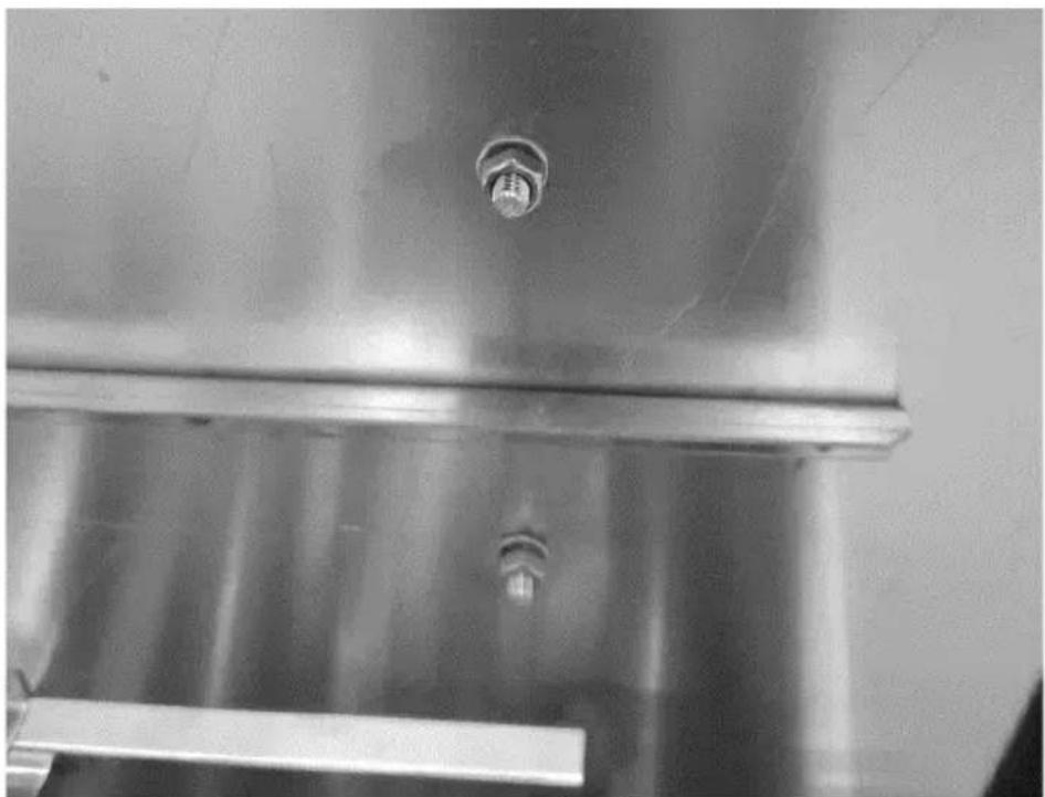
natural_image
Close-up of a metallic industrial component with a bolt and flange (no visible text or symbols)natural_image
Technical diagram showing two mechanical assembly states with directional arrows indicating movement (no text or symbols present)natural_image
Technical line drawing of a mechanical assembly with no visible text or symbols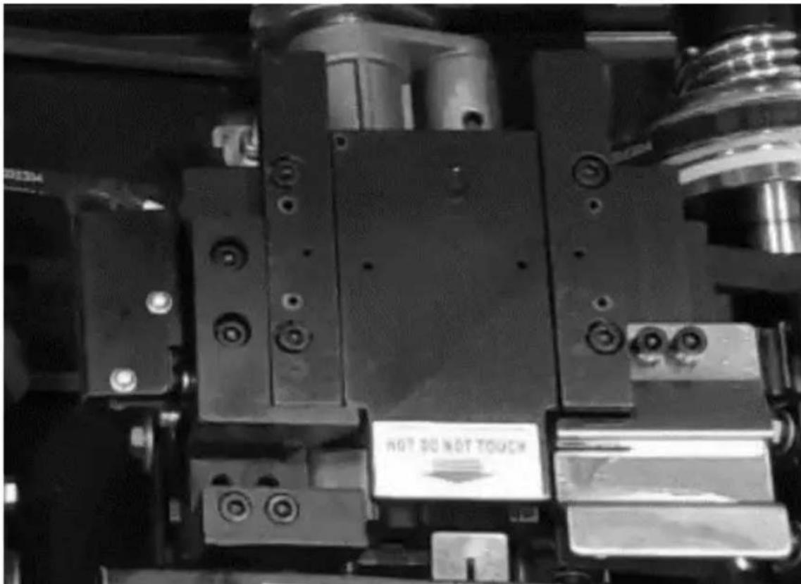
| Parameter description | Parameter value |
| Product name | Semiautomatic strapping machine |
| Model | MSW-PASO SSM30 |
| Supply voltage [V~] / Frequency [Hz] | 230/50 |
| Rated power [W]. | 320 |
| Safety class | 1 |
| Dimensions [width x depth x height; mm] | 900 x 580 x 800 |
| Weight [kg] | 84.2 |
| Worktop dimensions [mm] | 895 x 575 |
| Supported tape width [mm] | 9-13 |
| Supported tape thickness {mm} | 0.5-1 |
| Tape tension force [N] | 30-450 |
| Sealing temperature | Adjustable in 9 steps (up to 45 °C) |
1. General Description
The manual is intended to assist in safe and reliable use. The product is designed and manufactured strictly according to technical specifications using the latest technology and components and maintaining the highest quality standards.
PLEASE CAREFULLY READ AND UNDERSTAND THIS INSTRUCTION MANUAL BEFORE OPERATION.
To ensure long and reliable operation of the device, make sure to operate and maintain it properly in accordance with the guidelines in this instruction manual. The technical data and specifications in this manual are up-to-date. The manufacturer reserves the right to make changes to improve the quality. Taking the technical progress and the possibility of reducing noise into account, the unit is designed and built in such a way that risks resulting from noise emissions are reduced to the lowest possible level.
Explanation of symbols
| CE | The product complies with applicable safety standards. |
 | Read the manual before use. |
 | Recyclable product. |
 | CAUTION! or WARNING! or REMEMBER! describing a given situation (general warning sign). |
 | Use the safety cover. |
 | CAUTION! Risk of electric shock! |
 | CAUTION! Spinning elements! |
 | CAUTION! Danger of crushing your hand!! |
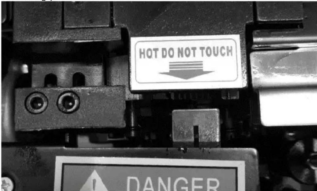
 | Don't touch! |
 | Caution! Hot surface can cause burns! |
 | For indoor use only. |

CAUTION! The figures in this manual are illustrative only and may vary in some details from the actual appearance of the product.
2. Safety of use

CAUTION! Read all safety warnings and instructions. Failure to follow the warnings and instructions may result in electric shock, fire, and/or serious injury or death.
The term "device" or "product" in the warnings and the description of the instructions refers to:
Semiautomatic strapping machine
2.1. Electrical safety
a) The plug of this device must fit into the outlet. Do not modify the plug in any way. Original plugs and matching outlets reduce the risk of electric shock.
b) Do not touch the device with wet or damp hands.
c) Do not use the cord in an unintended manner. Never use it to carry the device or to pull the plug out of the socket. Keep the cord away from heat sources, oil, sharp edges, or moving parts. Damaged or tangled cords increase the risk of electric shock.
d) Do not use the unit if the power cord is damaged or shows signs of wear. A damaged power cord should be replaced by a qualified electrician or the manufacturer's service department.
e) To avoid electric shock, do not immerse the cable, plug, or the appliance itself in water or other liquid. Do not use the appliance on wet surfaces.
f) CAUTION – DANGER TO LIFE! When cleaning or using the appliance, never immerse it in water or other liquids.
g) Do not use the appliance in rooms with very high humidity / in the immediate vicinity of water tanks!
h) Do not allow the machine to get wet. Risk of electric shock!
i) Before the initial use, please check whether the type of current and mains voltage corresponds to those indicated on the rating plate.
2.2. Safety in the workplace
a) Keep the work area tidy and well-lit. Disorder or poor lighting can lead to accidents. Be foresighted, watch what you are doing, and use common sense when using the unit.
b) Do not use the unit in an explosive area, for example in the presence of flammable liquids, gases, or dust. The unit produces sparks that can ignite dust or fumes.
c) If you find any damage or irregularities in the operation of the product, immediately turn it off and report it to an authorized person.
d) If you have any doubts as to whether the unit is working properly or if it is damaged, contact the manufacturer's service department.
e) Repairs to the device may only be carried out by the manufacturer's service. Do not attempt to repair the product on your own!
f) In case of open flames or fire, use only dry powder or snow (CO2) fire extinguishers to extinguish the live equipment.
g) No children or unauthorized persons are allowed in the work area. Inattention can cause losing control of the unit.
h) Check the condition of the safety stickers regularly. If the stickers are illegible, they must be replaced.
i) Keep these instructions for use for future reference. If the unit is to be passed on to third parties, the operating instructions must also be handed over together with the unit.
j) Keep packaging components and small installation parts out of the reach of children.
k) Keep the device away from children and animals.
I) When using this product together with other devices, also follow the other instructions for use.

Remember! Keep children and other bystanders safe while operating the equipment.
2.3. Personal safety
a) Keep the work area tidy and well lit. Disorder or poor lighting can lead to accidents. Be foresighted, watch what you are doing, and use common sense when using the unit.
b) Do not use the unit in an explosive area, for example in the presence of flammable liquids, gases, or dust. The unit produces sparks that can ignite dust or fumes.
c) The machine is not intended to be used by persons (including children) with reduced mental, sensory, or intellectual functions or persons who lack experience and/or knowledge unless they are supervised or have been
instructed by a person responsible for their safety on how to operate the machine.
d) Please be attentive and use common sense when operating this equipment. A moment's inattention during operation may result in serious personal injury.
e) To prevent accidental start-up, make sure the switch is in the off position before connecting to a power source.
f) Do not overestimate your capabilities. Maintain body balance and equilibrium at all times during operation. This allows for better control of the machine in unexpected situations.
g) Do not wear loose clothing or jewelry. Keep hair, clothing, and gloves away from moving parts. Loose clothing, jewelry, or long hair can be caught in moving parts.
h) Before switching the unit on, remove any regulating tools or keys. Any tools or keys left in the rotating part of the unit may cause injury.
i) The product is not a toy. Children should be watched to ensure that they do not play with the product.
j) Do not place your hands or any objects inside the running device!
k) Keep the device away from children and animals.
I) When using this product together with other devices, also follow the other instructions for use.
2.4. Safe use of the device
a) Do not use the device if the "ON / OFF" switch does not work properly (does not turn the device on and off). Units that cannot be controlled by the switch are unsafe, cannot operate, and must be repaired.
b) Disconnect the device from the power supply before adjusting, cleaning, or servicing. This precaution reduces the risk of accidental start-up.
c) Keep unused product out of the reach of children and anyone unfamiliar with the device or this manual. Products are dangerous when used by inexperienced users.
d) Keep the product in good working order. Check before each use for general damage or damage to moving parts (cracks in parts and components or any other condition that may affect the safe operation of the device). If damaged, return the device for repair before use.
e) Keep the product out of the reach of children.
f) Repairs and maintenance should be carried out by qualified personnel using only original spare parts. This will ensure the safety of use.
g) To ensure the designed operational integrity of the device, do not remove factory-installed covers or loosen screws.
h) Avoid situations where the unit stops working because it is handling a heavy load. This can cause overheating of the drive elements and consequent damage to the equipment.
i) Do not touch any moving parts or accessories unless the device is unplugged.
j) Do not move, shift, or rotate the device while in operation.
k) Clean the device regularly to prevent permanent dirt build-up.
I) Do not exceed the recommended supply pressure as this may damage the unit.
m) The product is not a toy. Cleaning and maintenance must not be performed by children without adult supervision.
n) Do not start up an empty unit.
o) Do not tamper with the device to alter its performance or design.
p) Keep the unit away from sources of fire and heat.
q) Do not overload the device.
r) Do not block the ventilation openings of the unit!
s) CAUTION! Some parts of the unit become very hot during operation – there is a danger of burning!
t) Avoid handling dirty and wet objects that could contaminate or damage the machine.

CAUTION! Although the product has been designed to be safe and has adequate safeguards and despite the additional safety features provided to the user, there is still a slight risk of accident or injury when handling the product. Caution and common sense are advised when using the product.
3. Instructions for use
The product helps secure parcels and items for transport and other purposes by wrapping and binding them with special tape.
The product is intended for commercial use.
The user is responsible for any damage resulting from misuse.
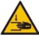
3.1. Product overview
A. Working top
B. Stoppers
C. Tape ejection slot
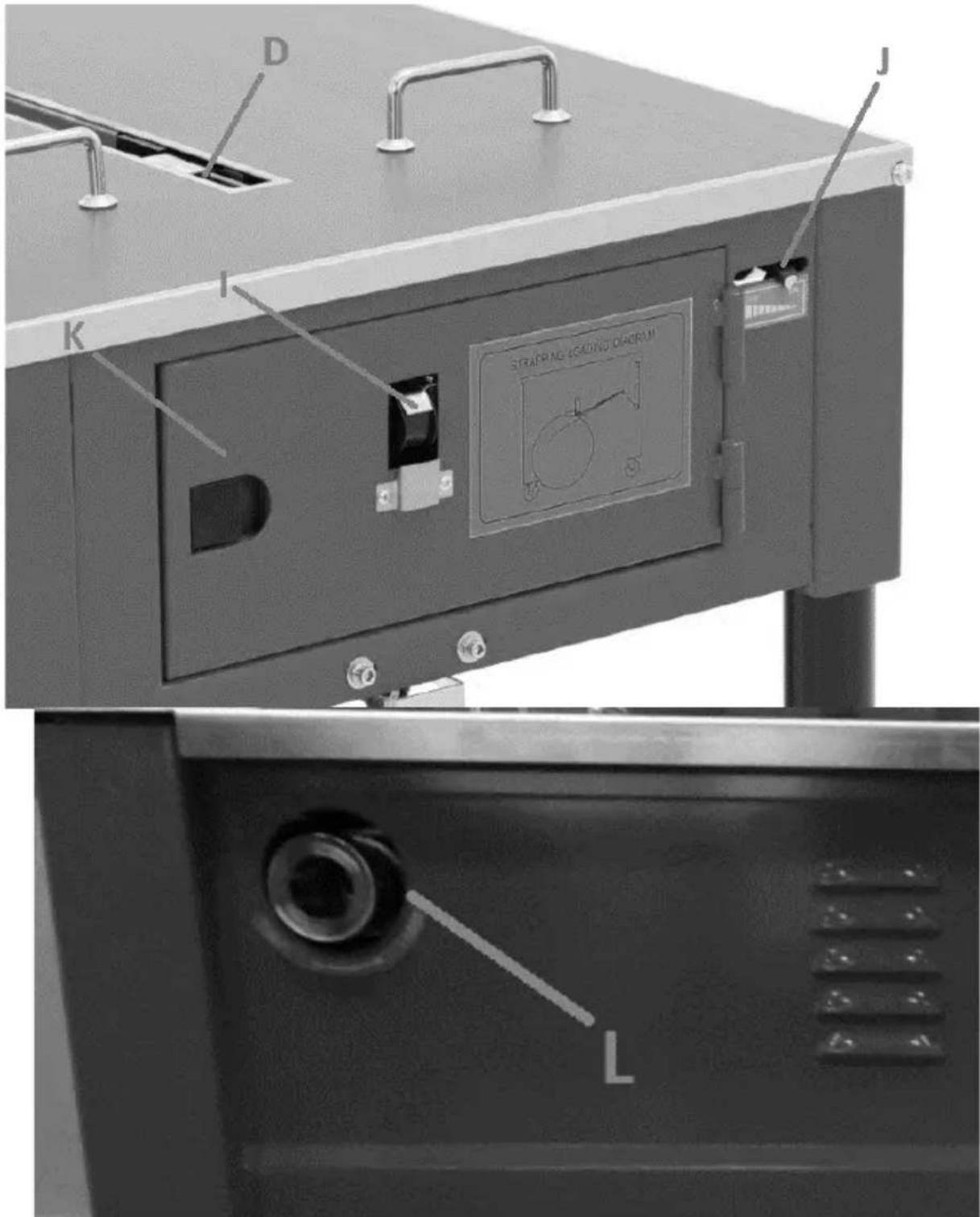
D. Hooking and sealing slot
E. Control panel
F. Power cord
G. Tape spool drum
H. Transport wheels (2x with brake and 2x without brake)
I. Tape routing inspection opening
J. Tape tension indicator
K. Inspection flap for the tape tightening mechanism
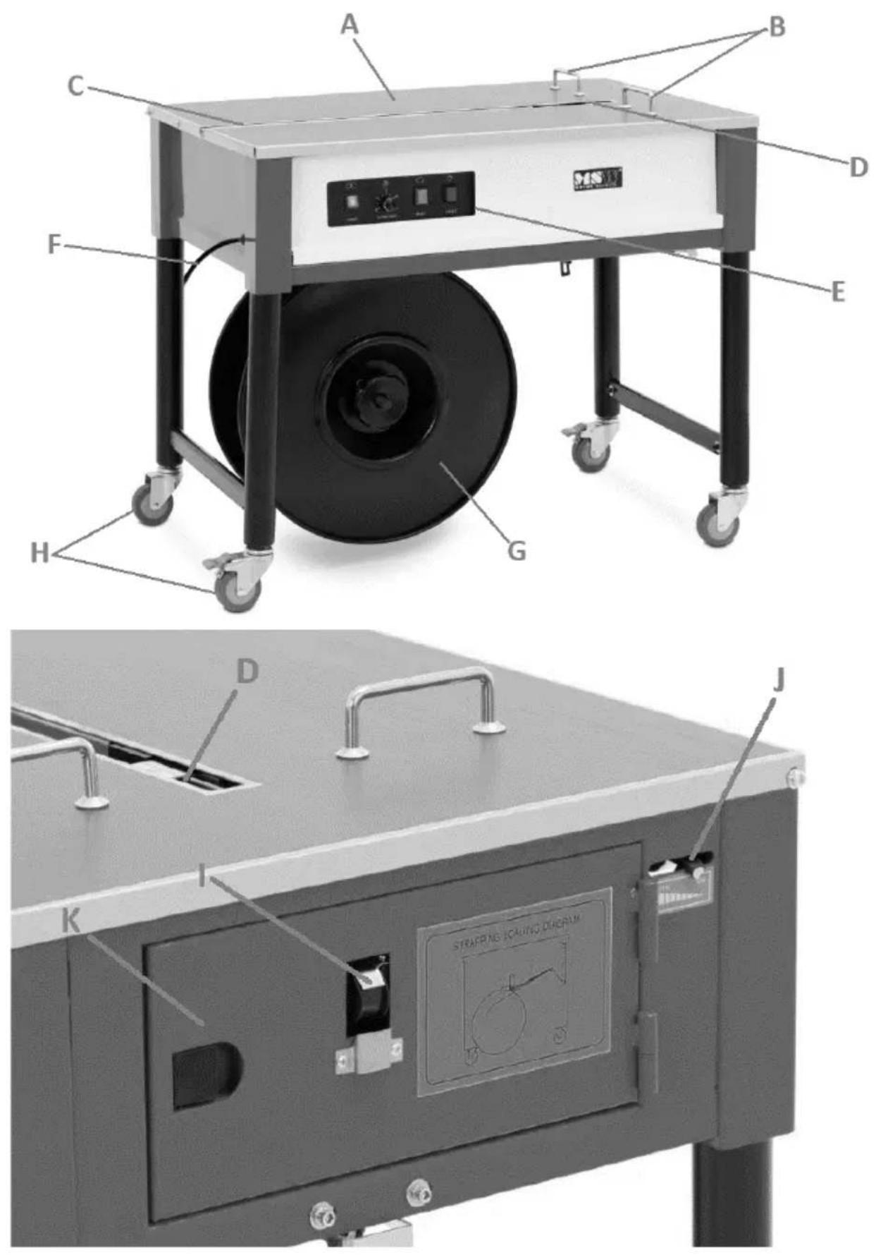
L. Tape tension adjustment knob
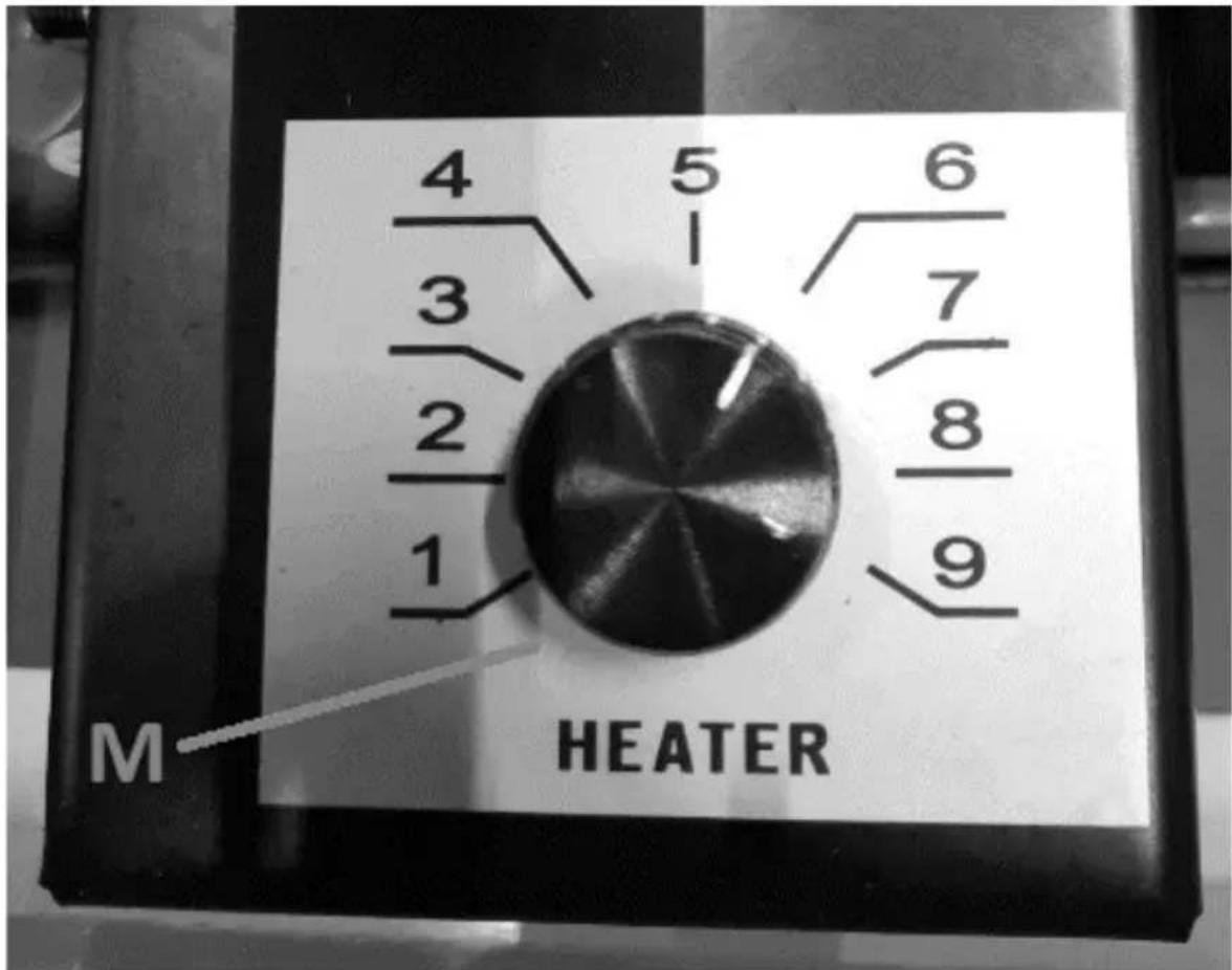
M. Sealing temperature control knob (inside the device)
3.2. Preparation for operation
POSITIONING OF THE UNIT
The ambient temperature must not exceed the range of 5-30 °C and the relative humidity should not exceed 85%. Place the unit in a way that ensures good air circulation. Ensure there is enough free space around the device for easy user access, at least 1 m. Keep the device away from any hot surfaces. Always operate the device on a level, stable, clean, fireproof, and dry surface and out of the reach of children and persons with impaired mental, sensory, and intellectual functions. Place the unit in such a way that the main plug can be reached at any time. Ensure that the power supply to the unit corresponds to that specified on the identification plate!
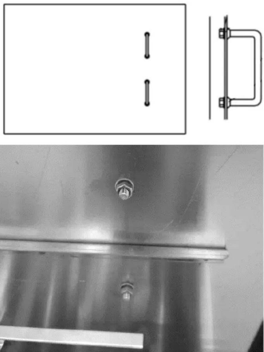
ASSEMBLY OF THE DEVICE
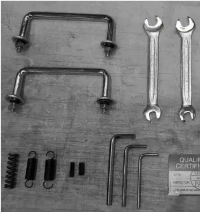
natural_image
Collection of metal wrenches and spring tools laid out on a textured surface, no text or symbols visible.The device is delivered almost ready for use, with the only assembly required being the attachment of both stoppers to the workbench using the provided tools. To do this, lift the worktop and fasten it with the nuts on the underside of the worktop:
3.3. Working with the device
3.3.1 Assembly of the tape spool
Attach the tape spool onto the drum and tighten it according to the diagram below (shown for narrow and wide tape), then tighten the coils with the handle (a). To prevent the tape from slipping off the spool, do not remove its protective packaging (such as film, paper, etc.) until the tape is loaded into the feeder mechanism.
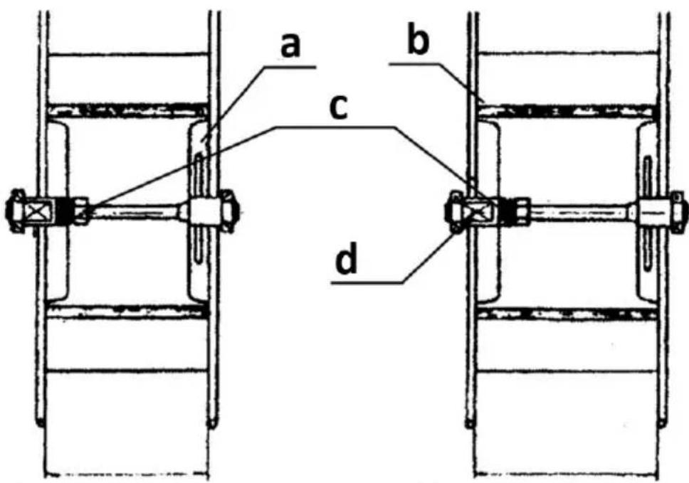
a) Handle
b) Drum
c) Sleeve with disc
d) Drum axis
3.3.2 Guiding the tape
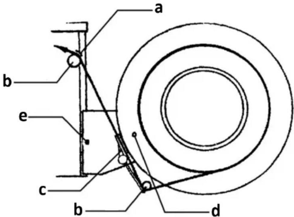
a) Tape guide
b) Tape guide roller
c) Brake levers
d) Stop screw
e) Clamping bolt
First, unscrew the top stop bolt of the drum / tape spool bracket (d), then straighten the brake lever (c) and reattach the stop bolt. Thread the beginning of the tape through the lower guiding roller (b), and then the upper roller (b), until its start exits from the machine table in the guide.
3.3.3 Operating the machine

- Power switch (ON/OFF)
- The knob for adjusting the length of the automatic tape ejection
- Button to reverse the ejected tape
- Manual tape eject button
a) Place the package on the workbench, pushing its side (which is to be wrapped with tape) against the stoppers.
b) Take the ejected tape and wrap it around the opposite side of the packet so that it adheres to it as closely as possible, and insert the beginning of the tape into the opening of the mechanism located in the slot on the other side of the packet.
c) When the mechanism senses the tape, it will automatically catch it and wrap the package by welding and cutting the tape around the side.
ATTENTION: be especially careful during automatic wrapping – do not keep hands or hands under the tape, as they may be caught and pinched!
3.3.4 Adjusting the feed slot to the tape
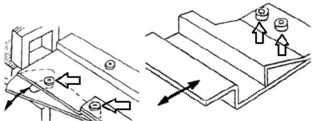
natural_image
Technical diagram showing two mechanical assembly states with directional arrows indicating movement (no text or symbols present)If the tape width is uneven or the dimensions differ from the one recently used, adjust the gap through which it moves. To do this, loosen the relevant screws and manually adjust the gap by positioning its component appropriately, then tighten the previously loosened screws. As a rule, the gap should be 0.5-1 mm wider than the thickness and width of the tape.
3.3.5 Sealing temperature control
The sealing temperature has a significant impact on the quality of the tape connection. Typically, this temperature is set to positions 4-5 on the dial inside the machine and does not require adjustment. However, if there are white marks on the surface of the sealer, the seal temperature is too high. If the surface of the strapping machine is moist, the set temperature is too low. When necessary, adjust it accordingly.
3.3.6 Tape tension adjustment
If the force applied to tension the tape around the object is too weak or strong, it can be adjusted using the knob (A) located on one side of
the machine. Turning clockwise increases the tension, while turning counterclockwise decreases it. The tension indicator (a) is located on the adjacent side of the machine:
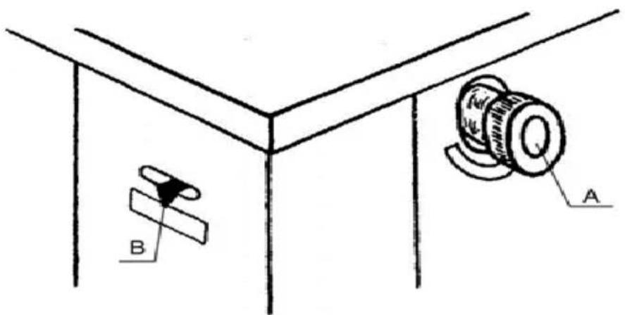
It is not necessary to adjust the tension each time, and the tape itself must not be tensioned too much.
3.4. Cleaning and maintenance
a) Pull the mains plug and let the unit cool down completely before cleaning, adjusting or replacing accessories and when the unit is not in use.
- Wait until the rotating parts stop.
b) Use only non-corrosive cleaning agents for cleaning the surfaces.
c) After each cleaning, all the parts should be dried well before the unit is used again.
d) Store the unit in a dry and cool place protected from moisture and direct sunlight.
e) Do not spray the unit with a stream of water or immerse it in water.
f) Make sure that no water enters through the ventilation openings in the casing.
g) Clean the ventilation openings with a brush and compressed air.
h) Perform regular inspections of the unit checking technical fitness and any damages.
i) Use a soft, damp cloth for cleaning.
j) Do not use sharp and/or metal objects (e.g. wire brush or metal spatula) for cleaning as they may damage the surface of the appliance material.
k) Regularly oil the points of the mechanism indicated in the picture below:
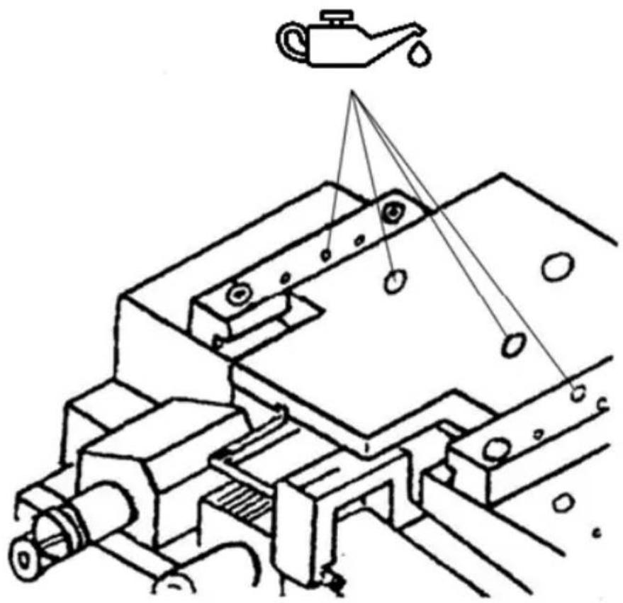
natural_image
Technical line drawing of a mechanical assembly with no visible text or symbols
DISPOSAL OF WASTE APPLIANCES
At the end of its useful life, this product should not be disposed of with normal household waste but should be taken to a collection point for the recycling of electrical and electronic equipment. This is indicated by the symbol on the product, operating instructions, or packaging. The materials used in this appliance are recyclable according to their marking. By reusing, recycling, or applying other forms of use of waste machines, you make a significant contribution to the protection of our environment.
Your local administration will provide you with information about the appropriate disposal point for used appliances.

natural_image
Collection of metal wrenches, spring scales, and a separate label on a wooden surface (no text or symbols on the objects themselves)natural_image
Technical diagram showing two mechanical assembly states with directional arrows indicating movement (no text or symbols present)natural_image
Technical line drawing of a mechanical assembly with no visible text or symbols
USUWANIE ZUŻYTYCH URZĄDZEŃ.
natural_image
Collection of metal wrenches, spring scales, and a certificate (no text or symbols on parts)natural_image
Pure technical line drawing of a rectangular panel and a vertical bracket (no text or symbols)
natural_image
Close-up of a metallic mechanical component with a bolt and flange (no visible text or symbols)natural_image
Technical diagram showing two mechanical assembly states with directional arrows indicating movement (no text or symbols present)natural_image
Technical line drawing of a mechanical assembly with no visible text or symbols
LIKVIDACE POUŽITÝCH ZAŘÍZENÍ.

natural_image
Collection of metal wrenches and spring tools laid out on a wooden surface, no text or symbols visible.natural_image
Pure technical line drawing of a rectangular panel and a separate mechanical bracket (no text or symbols)
natural_image
Close-up of a metallic industrial container with a bolt and horizontal bar (no visible text or symbols)natural_image
Technical diagram showing two mechanical assembly states with directional arrows indicating movement (no text or symbols present)natural_image
Technical line drawing of a mechanical assembly with no visible text or symbols
ÉLIMINATION DES APPAREILS USAGÉS.

natural_image
Collection of metal wrenches and spring components laid out on a textured surface (no text or symbols visible)natural_image
Pure technical line drawing of a rectangular panel and a separate mechanical bracket (no text or symbols)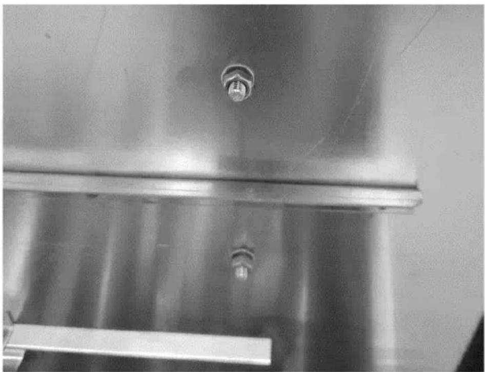
natural_image
Close-up of a metallic industrial container with a bolt and horizontal bar (no visible text or symbols)natural_image
Technical diagram showing two mechanical assembly states with directional arrows indicating movement or force (no text or symbols present)natural_image
Technical line drawing of a mechanical assembly with no visible text or symbols
SMALTIMENTO DEI DISPOSITIVI USURATI.


natural_image
Pure technical line drawing of a rectangular panel and a separate mechanical bracket (no text or symbols)
natural_image
Close-up of a metallic industrial container with a bolt and horizontal bar (no visible text or symbols)natural_image
Technical diagram showing two mechanical assembly states with directional arrows indicating movement (no text or symbols present)natural_image
Technical line drawing of a mechanical assembly with no visible text or symbols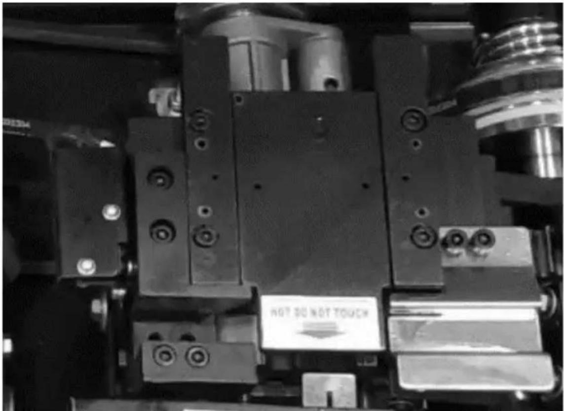


natural_image
Collection of metal wrenches and spring components laid out on a textured surface (no text or symbols visible)natural_image
Pure technical line drawing of a rectangular panel with two vertical cylindrical features and a side view of a mechanical bracket (no text or symbols)
natural_image
Close-up of a metallic industrial component with a bolt and flange (no visible text or symbols)natural_image
Technical diagram showing two mechanical assembly states with directional arrows indicating movement (no text or symbols present)natural_image
Technical line drawing of a mechanical assembly with no visible text or symbols
APPARATETS PLACERING
natural_image
Collection of metal wrenches and spring tools laid out on a textured surface, no text or symbols visible.natural_image
Pure technical line drawing of a rectangular panel and a mechanical bracket (no text or symbols)
natural_image
Close-up of a metallic industrial container with a bolt and flange (no visible text or symbols)natural_image
Technical diagram showing two mechanical assembly states with directional arrows indicating movement (no text or symbols present)natural_image
Technical line drawing of a mechanical assembly with no visible text or symbols
BORTSKAFFELSE F BRUGT UDSTYR.
natural_image
Collection of metal wrenches, spring scales, and a certificate (no text or symbols on parts)natural_image
Technical diagram showing two mechanical assembly states with directional arrows indicating movement or force (no text or symbols present)natural_image
Technical line drawing of a mechanical assembly with no visible text or symbols
LAITTEISTOJEN HÄVITTÄMINEN
natural_image
Collection of metal wrenches and spring components laid out on a wooden surface, with a 'QUALIFY CERTIFICATE' label visible (no text on main objects)natural_image
Technical diagram showing two mechanical assembly states with directional arrows indicating movement (no text or symbols present)natural_image
Technical line drawing of a mechanical assembly with no visible text or symbols
VERWIJDERING VAN GEBRUIKTE APPARATEN:
natural_image
Collection of metal wrenches, spring scales, and a certificate (no text or symbols on parts)natural_image
Pure technical line drawing of a rectangular panel with two vertical bars and a side view of a mechanical bracket (no text or symbols)
natural_image
Close-up of a metallic mechanical component with a bolt and flange (no visible text or symbols)natural_image
Technical diagram showing two mechanical assembly states with directional arrows indicating movement (no text or symbols present)natural_image
Technical line drawing of a mechanical assembly with no visible text or symbols
KASSERING AV BRUKTE ENHETER


PLACERING AV APPARATEN
natural_image
Collection of metal wrenches, springs, and fasteners arranged on a textured surface (no text or symbols visible)natural_image
Pure technical line drawing of a rectangular panel and a separate mechanical bracket (no text or symbols)
natural_image
Close-up of a metallic industrial container with a bolt and horizontal bar (no visible text or symbols)natural_image
Technical diagram showing two mechanical assembly states with directional arrows indicating movement (no text or symbols present)natural_image
Technical line drawing of a mechanical assembly with no visible text or symbols
KASSERING AV ANVÄNDA APPARATER

natural_image
Collection of metal wrenches and spring tools laid out on a wooden surface, no text or symbols visible.natural_image
Pure technical line drawing of a rectangular panel and a separate mechanical bracket (no text or symbols)
natural_image
Close-up of a metallic industrial container with a bolt and horizontal bar (no visible text or symbols)natural_image
Technical diagram showing two mechanical assembly states with directional arrows indicating movement (no text or symbols present)natural_image
Technical line drawing of a mechanical assembly with no visible text or symbols


A. Pracovná doska
B. Zátky
C. Slot na vysunutie pásky
D. Hákovací a tesniaci otvor
E. Ovládací panel
F. Napájací kábel
G. Bubon s páskovou cievkou
H. Transportné kolieska (2x s brzdou a 2x bez brzdy)
I. Kontrolný otvor vedenia pásky
J. Indikátor napätia pásky
K. Revízna klapka pre mechanizmus utahovania pásky
L. Gombík na nastavenie napätia pásky
M. Gombík ovládania teploty tesnenia (vo vnútri zariadenia)
natural_image
Collection of metal wrenches and spring components laid out on a textured surface (no text or symbols visible)natural_image
Pure technical line drawing of a rectangular panel with two vertical cylindrical features and a separate U-shaped bracket (no text or symbols)
natural_image
Close-up of a metallic industrial container with a bolt and side panel (no visible text or symbols)natural_image
Technical diagram showing two mechanical assembly states with directional arrows indicating movement (no text or symbols present)natural_image
Technical line drawing of a mechanical assembly with no visible text or symbols
LIKVIDÁCIA POUŽITÝCH ZARIADENÍ
For the disposal of the device please consider and act according to the national and local rules and regulations.
CONTACT
expondo Polska sp. z o.o. sp. k.