FPLAT35 WMAX - Vibratory compactor MSW - Free user manual and instructions
Find the device manual for free FPLAT35 WMAX MSW in PDF.

| Brand | MSW |
| Model | FPLAT35 WMAX |
| Type | Reversible vibratory plate compactor |
| Engine | 196 cm³, gasoline |
| Forward speed | 22 m/min |
| Compaction depth | 35 cm |
| Excitation frequency | 5040 vpm |
| Centrifugal force | 25,000 N |
| Plate size | 620 × 400 mm |
| Sound power level | 105 dB(A) |
| Dimensions (L × W × H) | 700 × 400 × 1200 mm |
| Weight | 124.5 kg |
| Power source | Gasoline, integrated tank |
| Starting type | Recoil starter |
| Travel direction | Forward, reverse, neutral (gear lever) |
| Exciter lubrication | Dextron III oil or equivalent, 500 ml |
| Periodic maintenance | Engine oil change, belt check, exciter oil change every 200 h |
| Operator protection | Hearing protection, safety glasses, gloves, safety shoes mandatory |
| Spare parts | V-belt, air filter, spark plug, oil |
| Repairability | Repairs by authorized service only; routine maintenance possible by user |
Frequently Asked Questions - FPLAT35 WMAX MSW
User questions about FPLAT35 WMAX MSW
0 question about this device. Answer the ones you know or ask your own.
Ask a new question about this device
Download the instructions for your Vibratory compactor in PDF format for free! Find your manual FPLAT35 WMAX - MSW and take your electronic device back in hand. On this page are published all the documents necessary for the use of your device. FPLAT35 WMAX by MSW.
USER MANUAL FPLAT35 WMAX MSW
natural_image
Technical line drawing of a mechanical device with two views: top shows internal components, bottom shows external housing (no text or symbols)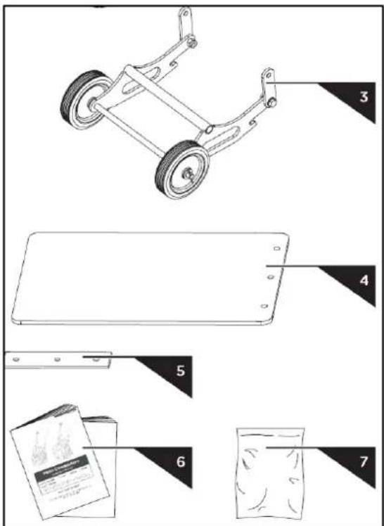
4.2. Montage
4.2.1. Oberer Griff

natural_image
Diagram of a manual lift or lever mechanism with a curved handle and spring, showing motion direction (no text or symbols)natural_image
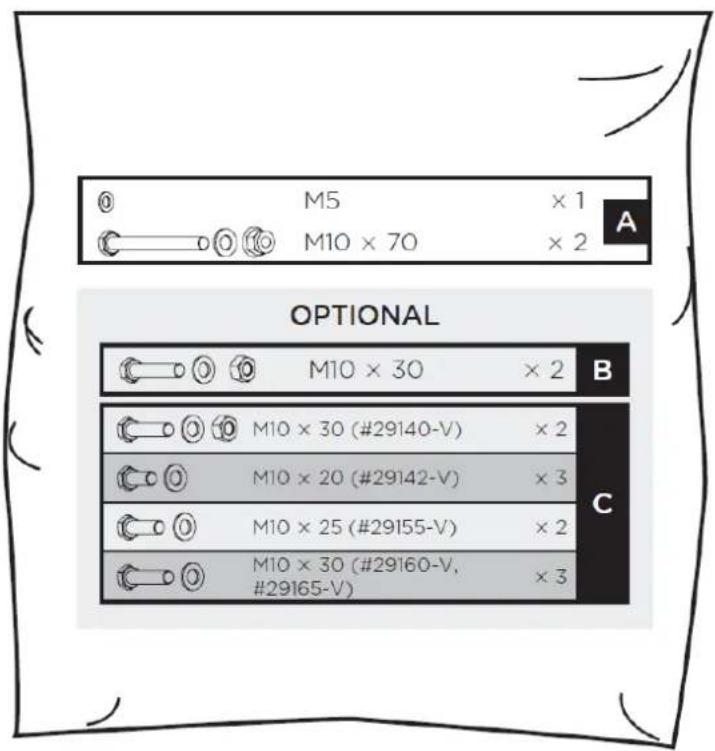
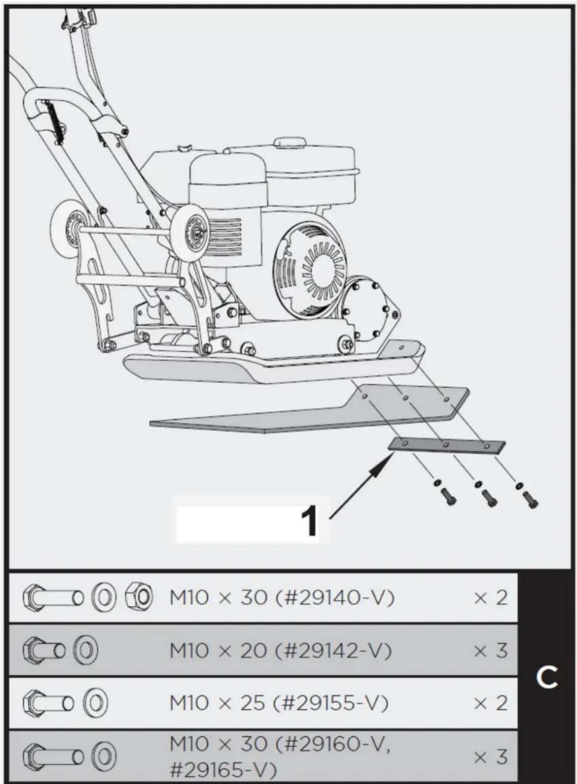
Technical line drawing of a manual lawn mower with labeled components (no text or symbols present)| M10 × 30 (#29140-V) × 2 | |
| M10 × 20 (#29142-V) × 3 | |
| M10 × 25 (#29155-V) × 2 | |
| M10 × 30 (#29160-V, #29165-V) × 3 |
1 - Klammerplatte
natural_image
Technical line drawing of a mechanical pump assembly with a container filled with granular material (no text or symbols)natural_image
Technical line drawing of a mechanical assembly with no visible text or symbolsnatural_image
Technical line drawing of a mechanical device with no visible text or symbols
natural_image
Technical line drawing of a mechanical assembly with two views: top shows internal components, bottom shows wheel wheels (no text or symbols)natural_image
Technical line drawing of a mechanical device with internal components and mounting brackets (no text or symbols)This User Manual has been translated for your convenience using machine translation. Reasonable efforts have been made to provide an accurate translation; however, no automated translation is perfect nor is it intended to replace human translators. The official User Manual is the English version. Any discrepancies or differences created in the translation are not binding and have no legal effect for compliance or enforcement purposes. If any questions arise related to the accuracy of the information contained in the User Manual, please refer to the English version of those contents which is the official version.
Technical data
| Parameter description | Parameter value | |
| Product name | Forward plate compactor | Reversible plate compactor |
| Model | MSW-FPLAT25 WMAX | MSW-FPLAT35 WMAX |
| Engine | 196 cc | 196 cc |
| Speed [m/min] | 25 | 22 |
| Compaction depth [cm] | 25 | 35 |
| Exciter speed [vpm] | 5500 | 5040 |
| Centrifugal force [N] | 11000 | 25000 |
| Plate size [cm] | 530 x 370 | 620 x 400 |
| Sound power level L_WA | 106 dB | 105 dB |
| Dimensions [width x depth x height; mm] | 1070 x 400 x 855 | 700 x 400 x 1200 |
| Weight [kg] | 57.3 | 124.5 |
1. General description
The user manual is designed to assist in the safe and trouble-free use of the device. The product is designed and manufactured in accordance with strict technical guidelines, using state-of-the-art technologies and components. Additionally, it is produced in compliance with the most stringent quality standards.
DO NOT USE THE DEVICE UNLESS YOU HAVE THOROUGHLY READ AND UNDERSTOOD THIS USER MANUAL.
To increase the product life of the device and to ensure trouble-free operation, use it in accordance with this user manual and regularly perform maintenance tasks. The technical data and specifications in this user manual are up to date. The manufacturer reserves the right to make changes associated with quality improvement. The device is designed to reduce noise emission risks to a minimum, taking into account technological progress and noise reduction opportunities.
Legend

The product satisfies the relevant safety standards.
Read instructions before use.
The product must be recycled.
WARNING! or CAUTION! or REMEMBER! Applicable to the given situation. (general warning sign)
Use ear protection. Exposure to loud noise may result in hearing loss.

Wear protective goggles.

Wear protective gloves.

Wear head protection.

Wear foot protection.

ATTENTION! Rotating parts, entanglement hazard!

WARNING! Toxic substances, danger of poisoning!

ATTENTION! Hot surface, risk of burns!

PLEASE NOTE! Drawings in this manual are for illustration purposes only and in some details may differ from the actual product.
2. Usage safety

ATTENTION! Read all safety warnings and all instructions. Failure to follow the warnings and instructions may result in serious injury or even death.
The terms "device" or "product" are used in the warnings and instructions to refer to:
Forward plate compactor / Reversible plate compactor
2.1. Engine operation safety
a) Do not smoke near the device. The device contains flammable substances.
b) W The engine gets very hot during operation. Do not touch the hot engine because it may cause burns.
c) Oil leaking from the machine should be reported to the appropriate services or comply with legal requirements applicable in the area of use.
d) Danger! Danger to health and the risk of explosion of the internal combustion engine
e) Poisonous carbon monoxide is present in the engine exhaust. Remaining in a carbon monoxide environment may lead to losing consciousness or even death. Do not run the engine in a closed space.
f) Protect the engine from heat, sparks and flame. Do not smoke in the vicinity of the chipper!
g) Petrol is flammable and explosive. Before refuelling the engine should be turned off and cooled down
h) Warning! Risk of engine damage due to wrong fuel.
i) Make sure that all users have read, understood and follow the manual.
j) Misuse or careless use of the device may cause serious injuries.
k) Before each cleaning, regulation, accessory change, or if the device is not in use, turn the engine off and completely cool the device.
I) Do not touch moving parts or accessories unless the engine is turned off and left to cool.
m) Stay away from moving and rotating parts as they may cause injury.
n) Do not use the machine if all protective covers are not installed.
o) Do not touch the silencer or other hot elements when the engine is hot it may cause serious burns.
p) Make sure that petrol is stored only in certified containers (e.g. canister).
q) Do not refuel near sparks, flames or lit cigarettes.
r) Stop the engine before refuelling. Never refuel while the engine is running or is still hot. Otherwise, spilled or evaporated fuel may catch fire from engine sparks or silencer heat.
s) Do not overfill fuel tank and avoid spilling petrol while refuelling. Spilled petrol or petrol fumes may catch fire. If petrol has been spilled, make sure that the area is dry before starting the engine.
t) After refuelling, make sure that the fuel tank cap is properly screwed on.
u) Do not operate the engine or refuel petrol in enclosed areas without appropriate ventilation.
v) Avoid operating the machine in enclosed spaces, tunnels or other poorly ventilated places as the exhaust fumes contain lethal/harmful fumes and gases. If operating the machine in such conditions is unavoidable, provide adequate exhaust extraction.
w) To transport: Stop the engine. Close and secure the fuel tank cap. Switch the fuel valve to the "OFF-O" position. Drain the fuel tank before long-distance transportation or on bumpy roads.
x) Keep flammable materials (petrol, matches, straw, etc.) away from the exhaust.
2.2. Safety in the workplace
a) Make sure the workplace is clean and well lit. A messy or poorly lit workplace may lead to accidents. Try to think ahead, observe what is going on and use common sense when working with the device.
b) Do not use the device in a potentially explosive environment, for example in the presence of flammable liquids, gases or dust. The device generates sparks which may ignite dust or fumes.
c) If you discover damage or irregular operation, immediately switch the device off and report it to a supervisor without delay.
d) If there are any doubts as to the correct operation of the device, contact the manufacturer's support service.
e) Only the manufacturer's service point may repair the device. Do not attempt any repairs independently!
f) In case of fire, use a powder or carbon dioxide (CO2) fire extinguisher (one intended for use on live electrical devices) to put it out.
g) Children or unauthorised persons are forbidden to enter a work station. (A distraction may result in loss of control over the device).
h) Use the device in a well-ventilated space.
i) The device produces dust and debris during operation. It is important to protect bystanders from their harmful effects.
j) Regularly inspect the condition of the safety labels. If the labels are illegible, they must be replaced.
k) Please keep this manual available for future reference. If this device is passed on to a third party, the manual must be passed on with it.
1) Keep packaging elements and small assembly parts in a place not available to children.
m) Keep the device away from children and animals.
n) If this device is used together with another equipment, the remaining instructions for use shall also be followed.

Remember! When using the device, protect children and other bystanders.
2.3. Personal safety
a) Do not use the device when tired, ill or under the influence of alcohol, narcotics or medication which can significantly impair the ability to operate the device.
b) The device is not designed to be handled by persons (including children) with limited mental and sensory functions or persons lacking relevant experience and/or knowledge unless they are supervised by a person responsible for their safety or they have received instruction on how to operate the device.
c) The device can be handled only by physically fit persons who are capable of handling it, properly trained, familiar with this manual and trained within the scope of occupational health and safety.
d) When working with the device, use common sense and stay alert. Temporary loss of concentration while using the device may lead to serious injuries.
e) Use personal protective equipment as required for working with the device, specified in section 1 (Legend). The use of correct and approved personal protective equipment reduces the risk of injury.
f) Do not overestimate your abilities. When using the device, keep your balance and remain stable at all times. This will ensure better control over the device in unexpected situations.
g) Do not wear loose clothing or jewellery. Keep hair, clothes and gloves away from moving parts. Loose clothing, jewellery or long hair may get caught in moving parts.
h) Remove all adjusting tools or spanners before turning the device on. A tool or spanner left in the revolving part of the device may cause injury.
i) Use eye, ear and respiratory protection.
j) The device is not a toy. Children must be supervised to ensure that they do not play with the device.
2.4. Safe device use
a) Do not use the device if the ON/OFF switch does not function properly (does not switch the device on and off). Devices which cannot be switched on and off using the ON/OFF switch are hazardous, should not be operated and must be repaired.
b) Do not overload the device. Use the appropriate tools for the given task. A correctly-selected device will perform the task for which it was designed better and in a safer manner.
c) When not in use, store in a safe place, away from children and people not familiar with the device who have not read the user manual. The device may pose a hazard in the hands of inexperienced users.
d) Keep the device in perfect technical condition. Before each use check for general damage and especially check for cracked parts or elements and for any other conditions which may impact the safe operation of the device. If damage is discovered, hand over the device for repair before use.
e) Keep the device out of the reach of children.
f) Device repair or maintenance should be carried out by qualified persons, only using original spare parts. This will ensure safe use.
g) To ensure the operational integrity of the device, do not remove factory-fitted guards and do not loosen any screws.
h) When transporting and handling the device between the warehouse and the destination, observe the occupational health and safety principles for manual transport operations which apply in the country where the device will be used.
i) Do not leave this appliance unattended while it is in use.
j) Clean the device regularly to prevent stubborn grime from accumulating.
k) The device is not a toy. Cleaning and maintenance may not be carried out by children without supervision by an adult person.
I) It is forbidden to interfere with the structure of the device in order to change its parameters or construction.
m) Keep the device away from sources of fire and heat.
n) During operation, the device generates vibrations and requires repetitive activities that may be harmful to user's hands and shoulders.
o) The user and the machine should be in a stable position on level ground. Make sure that the machine does not tip over, slip or fall during operation or when left unattended.
p) Before using the device near excavation, make sure that excavation walls are stable and will not collapse under vibration.
q) Make sure that there are no live electrical cables, gas, water or other telecommunication infrastructure in the area to be compacted because they may become damaged by vibrations.
r) Do not stand on the device, whether it is currently in use or not.
s) Slipping, tripping or falling are the main causes of serious injury or death. Be careful of uneven or slippery working surfaces as well as unprotected holes and excavations.
t) The device is heavy and should be moved and positioned by two sufficiently strong people. Use the handles on the machine and proper heavy-lifting techniques.

ATTENTION! Despite the safe design of the device and its protective features, and despite the use of additional elements protecting the operator, there is still a slight risk of accident or injury when using the device. Stay alert and use common sense when using the device.
3. Use guidelines
The machine is used for soil compaction and surface smoothing by transmitting vibrations through a vibrating plate whose power is generated by an internal combustion engine. The machine is suitable for smoothing surfaces such as soil, sediment, beaches, sandy surfaces or finishing asphalt or paved surfaces.
The user is liable for any damage resulting from unintended use of the device.
4. MSW-FPLAT25 WMAX MODEL
4.1. Device description
natural_image
Technical line drawing of a mechanical device with two views (1 and 2), no visible text or symbols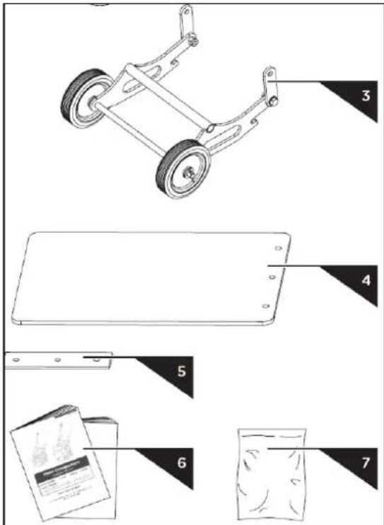
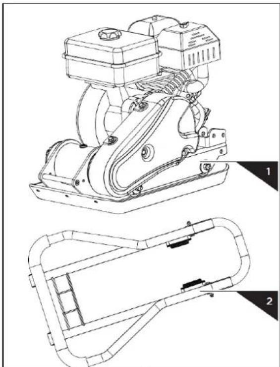
- Plate Compactor Chassis with Engine and Transmission
- Handle
- Folding Wheels Kit (Optional)
- Paving Pad (Optional)
- Clamp Plate (Optional)
- Operator's Manual & Engine Manual
- Hardware Bag, Including:
4.2. Assembly
4.2.1. Upper handle
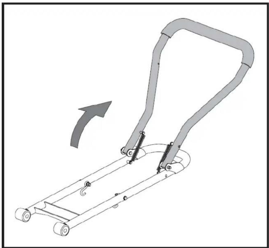
natural_image
Diagram of a manual lift or pulley system with a handle and spring, showing motion direction (no text or symbols)Unfold the Handle as shown.
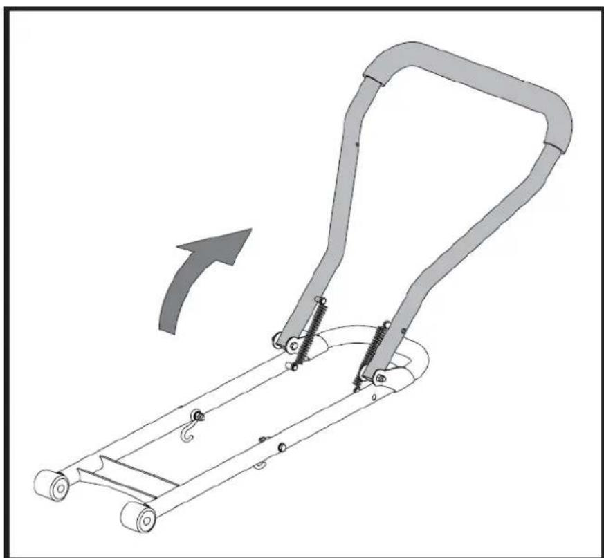
4.2.2. Handle
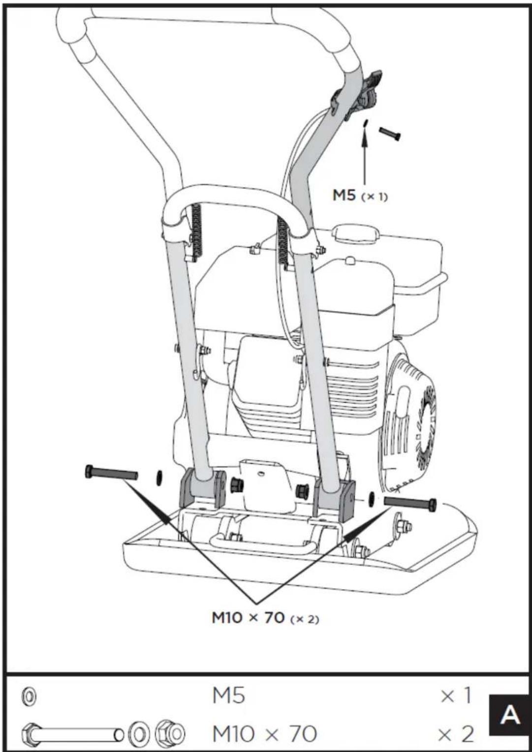
- Mount the Handle as shown. Make the Handle Ends slot into the channels provided by the Engine Deck. Place flat washers 10, followed by hex bolts M10x70 at the outer side, and tighten with lock nuts M10 at the inner side.
- Unscrew bolt 5x35 from throttle control. Secure the Throttle Control onto the Upper Handle with a flat washer 5 and the bolt 5X35 that just were unscrewed.
Fasten the Throttle Control cable with cable fasteners.
4.2.3. Folding Wheels Kit (Optional)
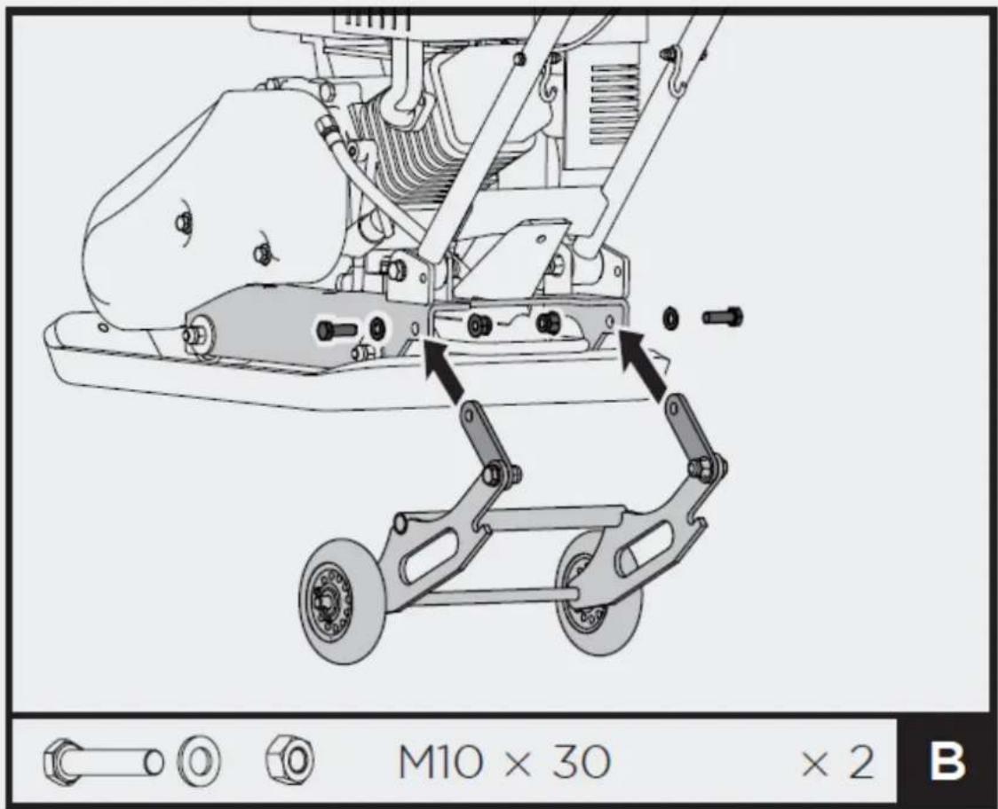
Line up the holes in the Link Plates and Engine Deck. Slide bolts M10x30 through the holes from one side, then lock nuts M10 from the other side. Tighten down.
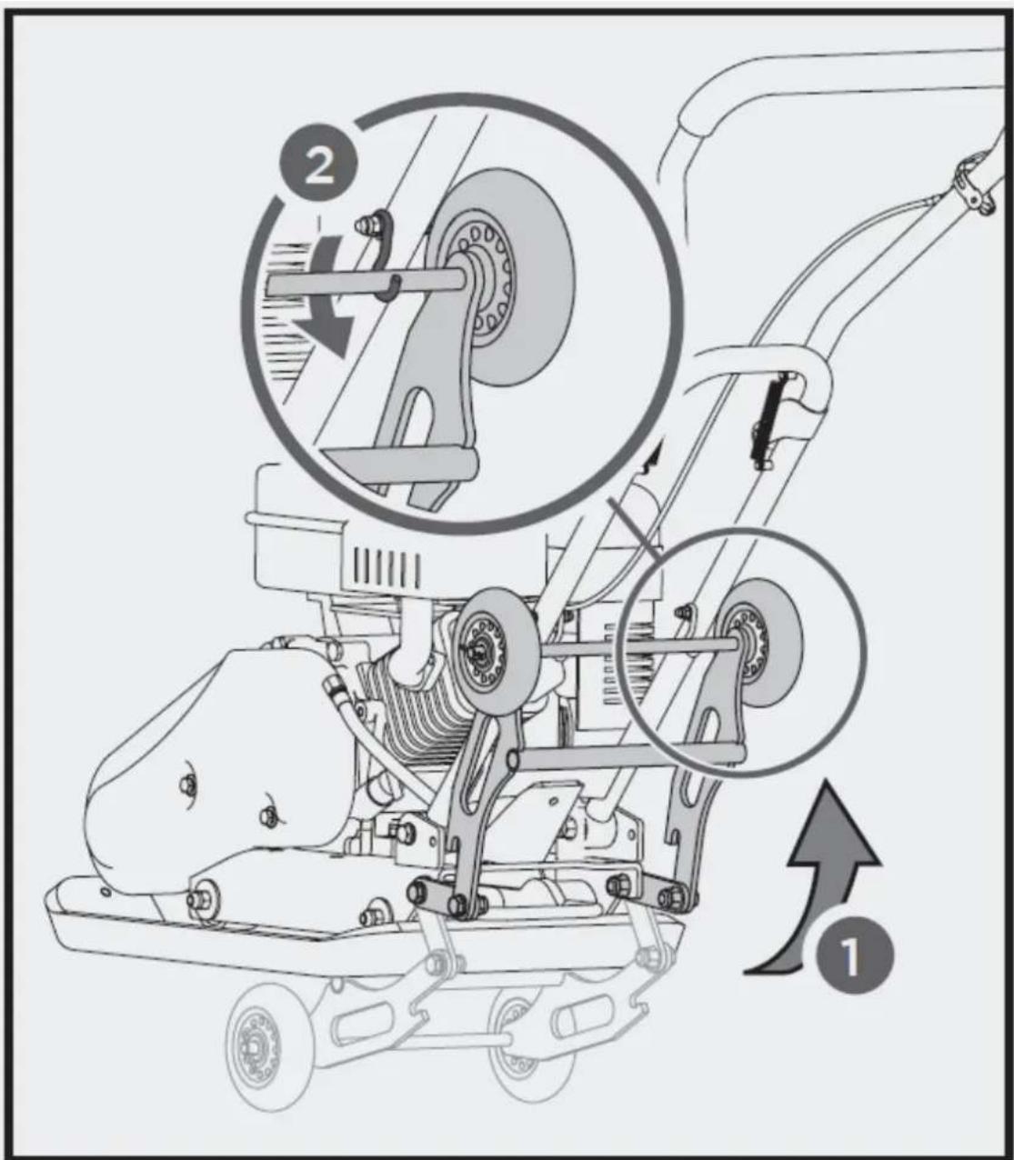
Before compacting, fold up the Wheel Kit as shown.
4.2.4. Paving Pad Kit (Optional)
4.2.5. Engine Oil
OIL HAS BEEN DRAINED FOR SHIPPING.
Failure to fill engine sump with oil before starting engine will result in permanent damage and void engine warranty.
-
Throttle Control
-
Operation Handle
-
Muffler
-
Air Cleaner
-
Fuel Tank
-
Belt Guard
-
Oil Drain Hose
-
Exciter
-
Base Plate
Fuel Valve Control
The fuel valve opens and closes the passage between the fuel tank and the carburettor. The fuel valve lever must be in the ON position for the engine to run. When the engine is not in use, leave the fuel valve lever in the OFF position to prevent carburettor flooding and to reduce the possibility of fuel leakage.
Throttle Control
The throttle lever controls engine speed. Moving the throttle lever makes the engine run faster or slower.
Engine Switch
The engine switch enables and disables the ignition system. The engine switch must be in the ON position for the engine to run. Turning the engine switch to the OFF position stops the engine.
Choke Lever
The choke lever opens and closes the choke valve in the carburettor. The closed position enriches the fuel mixture for starting a cold engine. The open position provides the correct fuel mixture for operation after starting, and for restarting a warm engine. Some engine applications use a remotely-mounted choke control rather than the engine-mounted choke lever.
Recoil Starter Grip
Pulling the starter grip operates the recoil starter to crank the engine.
Oil Drain Hose
Running the engine with dirty oil can cause premature engine wear and failure. Changing oil regularly is extremely important. The flexible oil drain hose is equipped to drain oil into appropriate receptacle.
Exciter
The eccentric shaft contained within exciter housing is driven at high speed by a clutch and belt drive system. This high speed shaft revolution causes the rapid lifting and downward ramming motion of the machine as well as imparting a forward motion.
4.3. Starting Engine
- Move the fuel valve lever to the ON position.
- To start a cold engine, move the choke to the CLOSE position. To restart a warm engine, leave the choke lever in the OPEN position.
- Move the throttle lever away from the SLOW position, about 1/3 of the way toward the FAST position.
- Turn the engine switch to the ON position.
- Operate the starter.
Recoil starter
Pull the starter grip lightly until you feel resistance, then pull briskly, return the starter grip gently. If the choke lever has been moved to the CLOSE position to start the engine, gradually move it to the OPEN
position as the engine warms up. After engine warms up, pull throttle lever to accelerate engine speed and place the shift stick at the desired position. Plate will begin vibrating and proceed with compacting.
4.3.1. Operating

Do not operate plate on concrete or on extremely hard, dry, compacted surfaces. The plate will rather than vibrate and could damage both plate and engine.
-
After engine warms up, pull throttle lever to accelerate engine speed. Plate will Begin vibrating and move forward.
-
The plate compactor is designed to run at an engine speed (engine take off shaft) of 3600 rpm (Normally considered full throttle). Running the engine at lower rpm's will result in a decrease of compaction force and lower travel speed. It will create excessive "out-of-synch" vibrations resulting in poor compaction, manoeuvrability, excessive wear to the machine, and discomfort to the operator.
-
In operation, guide the machine, but let the compactor do the work. Bearing down on the handle is unnecessary and causes shock absorber wear.
-
On level surfaces the compactor moves forward rapidly. On uneven surfaces or inclines, light forward pressure on handle may be required to assist the compactor in moving forward.
-
The number of passes required to reach a desired compaction level will depend on the type and moisture content of soil. Maximum soil compaction has been reached when excessive kickback is noticed.
- When using a compactor on asphalt, Water Sprinkler Kit is required to help prevent the bottom plate from adhering to the hot asphalt surface.
- When using plate on paving stones, attach a pad to the bottom of the plate to prevent chipping or grinding surface of the stones. A special urethane pad designed for this purpose is available as an optional accessory.
- While a certain amount of moisture in the soil is necessary, excessive moisture may cause soil particles to stick together and prevent good compaction. If soil is extremely wet, allow it to dry before compacting.
- If soil is so dry as to create dust clouds while operating plate, some moisture should be added to the ground material to improve compacting. This will also reduce service to the air filter.
Stopping Engine
To stop the engine in an emergency, simply turn the engine switch to the OFF position. Under normal conditions, use the following procedure.
- Move the throttle lever to the SLOW position.
- Let engine idle for one or two minutes.
- Turn the engine switch to the OFF position.
- Turn the fuel valve lever to the OFF position.
Do not move choke control to CLOSE to stop engine. Backfire or engine damage may occur.
Idle Speed
Set throttle control lever to its “low” position to reduce stress on the engine when compacting is not being performed. Lowering the engine speed to idle the engine will help extend the life of the engine, as well as conserve fuel and reduce the noise level of the machine.
4.4. Maintenance
4.4.1. Preventive Maintenance
- Turn off engine. Engine must be cool.
- Keep the engine's throttle lever in its SLOW position, and remove spark plug wire from spark plug and secure.
- Inspect the general condition of the plate compactor. Check for loose screws, misalignment or binding of moving parts, cracked or broken parts, and any other condition that may affect its safe operation.
- Remove all debris from the plate compactor with a soft brush, vacuum, or compressed air. Then use a premium quality lightweight machine oil to lubricate all moving parts.
- Clean the bottom of the compactor base as soon as it begins to pick up soil being compacted. The unit can not do a good job if the bottom surface is not smooth and clean.
- Replace spark plug wire.
Never use a “pressure washer” to clean your plate compactor. Water can penetrate tight areas of the unit and cause damage to spindles, pulleys, bearings, or the engine. The use of pressure washers will result in shortened life and reduce serviceability.
4.4.2. Checking V-Belt(s)
To ensure optimum power transmission from the engine to the eccentric shaft, the V-belt(s) must be in good condition and operate under proper tension.
- Turn off engine. Engine must be cool.
- Remove the belt guard to access the V-belt(s).
- Check the condition of the V-belt(s). If any V-belt is cracked, frayed, or glazed, it should be replaced as soon as convenient.
- Check the V-belt tension by squeezing them in the centre. The normal deflection on each side should be 9mm (3/8") to 13mm (1/2") with moderate pressure from your thumb or finger.
On new machines or after installing a new belt, check belt tension after first 20 hours of operation. Check and adjust belt every 50 hours thereafter.
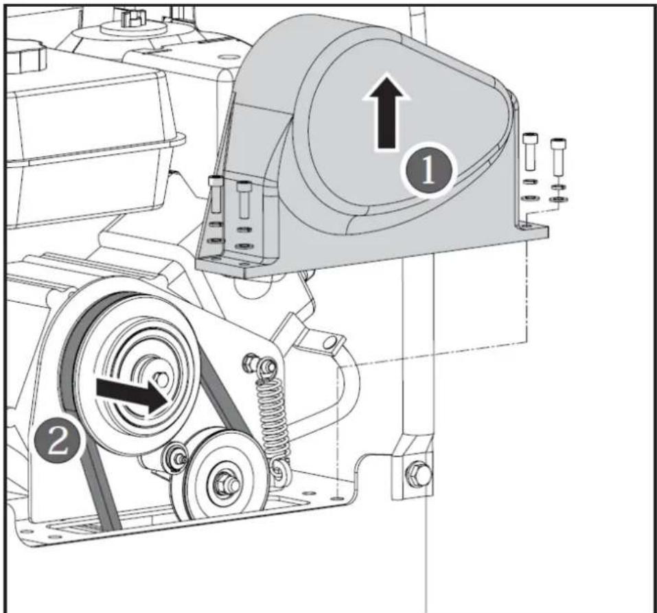
Tensioning V-Belt(s)
Proper belt tension is critical to good performance. Proper adjustment will assure long belt life. Too much or too little belt tension will cause premature belt failure.
- Loosen 4 engine mount bolts (do not remove) only enough to move the engine forward.
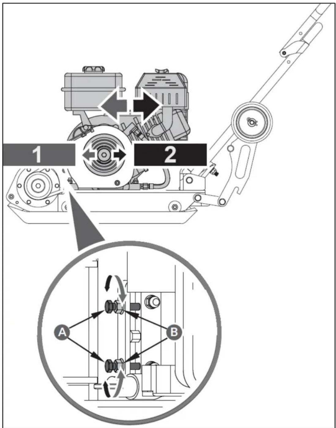
1 - Loosen
2 - Tighten
A - Adjustment Bolts
B - Jam Nuts
- Loosen the jam nuts B, leaving enough space between the nut and bracket.
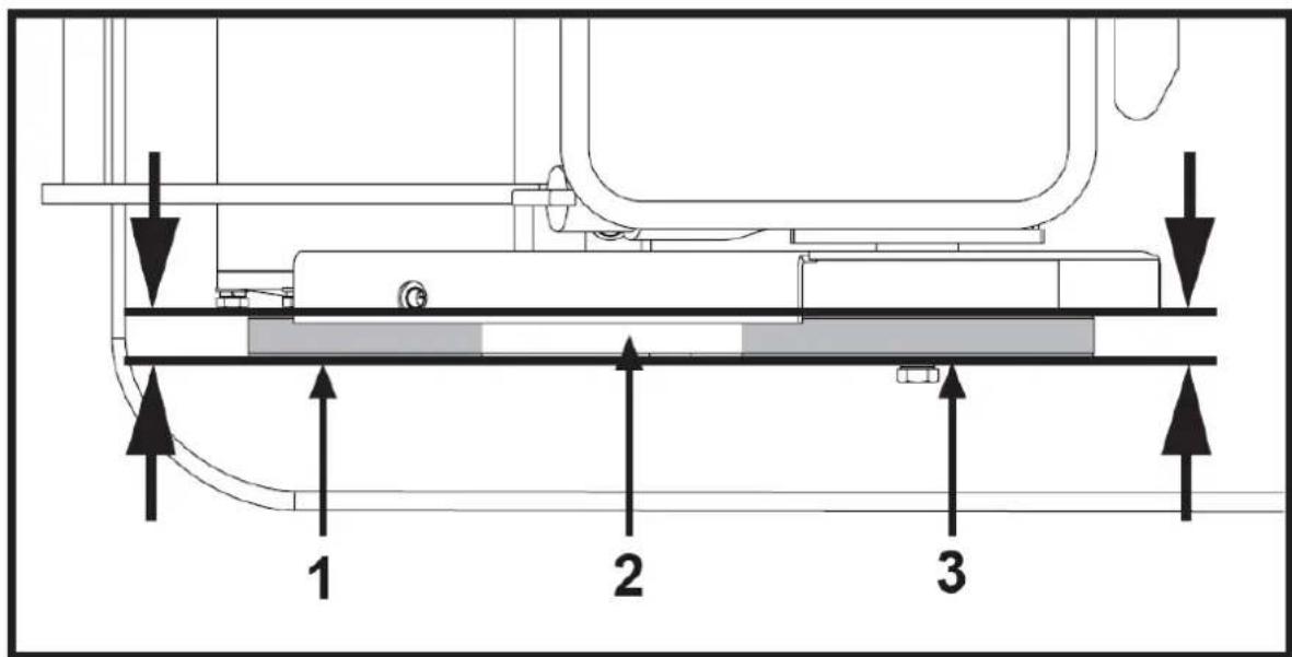
1 - Exciter Pulley
2 - V-belt
3 - Clutch Pulley
- Push engine toward the back of the plate by turning the adjustment bolts A to remove any slack in V-belt(s).

When adjusting the belt(s), make sure that the clutch pulley is in alignment with exciter pulley.
-
When the V-belt tension is correct, tighten the jam nuts B against the bracket.
-
Tighten the engine mount bolts.
-
Replace the belt guard.

If the adjustment bolts have no more adjustment left, the belt(s) may have to be replaced.
4.4.3. Replacing V-Belt(s)
Both V-belts should be replaced at the same time because they will wear evenly through normal use. Work on one belt at a time.
-
Loosen four engine mount bolts (do not remove) only enough to move the engine forward.
-
Loosen the jam nuts B and bolts A shown in above figure.
-
Slide the engine toward the front of plate and slip the old V-belt(s) off of the wheel pulley and install the new V-belt(s) in their place.
-
Position the V-belt(s) over the engine pulley.
-
Move the engine back.

When adjusting the belt(s), make sure that the clutch pulley is in alignment with exciter pulley.
-
When the V-belt tension is correct, tighten the jam nuts B and the engine mount bolts.
-
Replace the belt guard.

When removing or installing the drive belt(s), be careful not to get your fingers caught between the and pulley.
4.4.4. Exciter Lubrication
The exciter housing is pre-serviced using Automatic Transmission Fluid Dextron III, Mercon, EXXON (ESSO) NUTO H-32 or its equivalent. Change fluid after 200 hours of operation.
- Let exciter cool before changing exciter oil.
natural_image
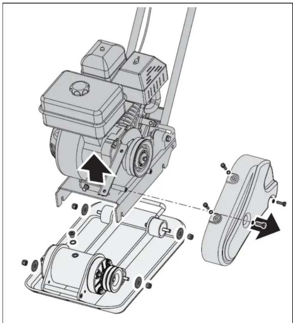
Technical diagram of a mechanical assembly with labeled parts, showing motor, gear, and housing components (no text or symbols present)- Remove the belt guard and V-belt(s).
- Remove the bolts that hold the deck to the housing.
- Lift entire deck with engine from housing.
natural_image
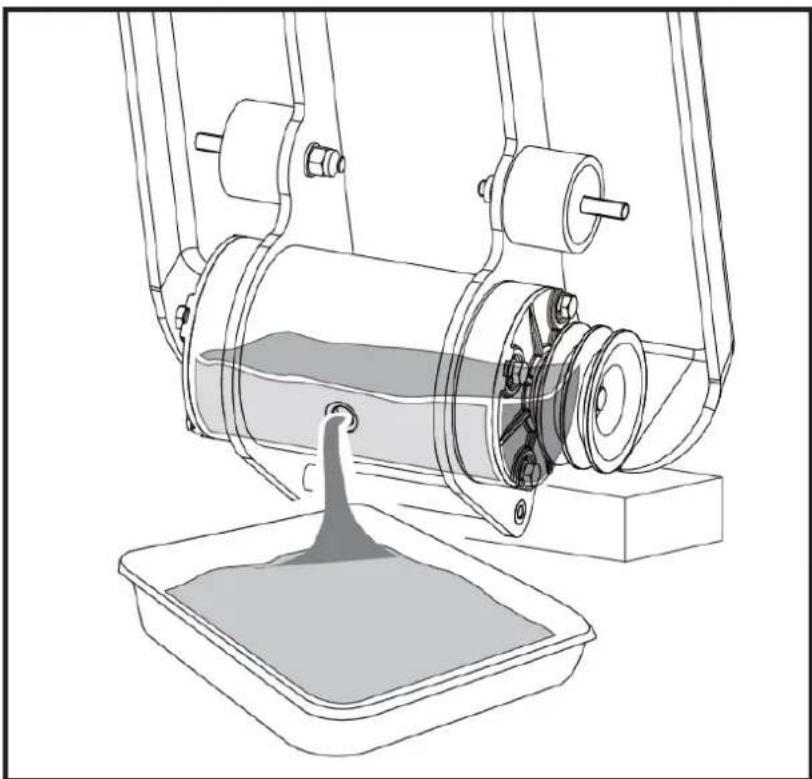
Technical line drawing of a mechanical device with a funnel inserted into a tray (no text or symbols)-
Remove pipe plug from top of exciter housing. Tilt housing upside down so oil drains from exciter. Examine oil for metal chips as a precaution to future problems.
-
Return plate housing to the upright position.
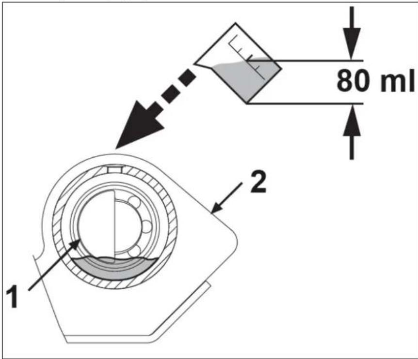
1 - Exciter Shaft
2 - Exciter
- Fill the exciter housing with exciter oil.

Do not overfill - overfilling can result in excessive temperatures in the exciter.
-
Apply pipe sealant to pipe plug and reinstall into top of exciter housing.
-
Reinstall deck, V-belt(s) and belt guard.
4.4.5. Lifting / Transport
To avoid burns or fire hazards, let engine cool before lifting / transporting machine or storing indoors.
natural_image
Technical line drawing of a mechanical assembly with no visible text or symbolsThe unit must be transported in the upright position to prevent fuel from spilling. Do not lay machine on its side or top. Secure or tie down unit using the lifting handle to prevent machine from sliding or tipping over.

Machine may fall and cause damage or injury if lifted incorrectly. Lift using handles at base of plate.
4.4.6. Storage
If the plate compactor will not be used for a period longer than 30 days, following the steps below to prepare your unit for storage.
-
Drain the fuel tank completely. Stored fuel containing ethanol or MTBE can start to go stale in 30 days. Stale fuel has high gum content and can clog the carburettor and restrict fuel flow.
-
Start the engine and allow it to run until it stops. This ensures no fuel is left in the carburettor. Run the engine until it stops. This helps prevent deposits from forming inside the carburettor and possible engine damage.
-
While the engine is still warm, drain the oil from the engine. Refill with fresh oil of the grade recommended in the Engine Manual.
-
Allow the engine to cool. Remove the spark plug and put 60 ml of SAE-30 of high quality motor oil into the cylinder. Pull the starter rope slowly to distribute the oil. Replace the spark plug.

Remove the spark plug and drain all of the oil from the cylinder before attempting to start the unit storage.
- Use clean cloths to clean off the outside of the compactor and to keep the air vents free of obstructions.

Do not use strong detergents or petroleum based cleaners when cleaning plastic parts. Chemicals damage plastics.
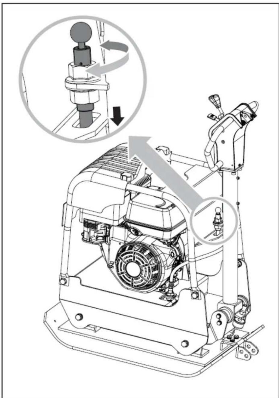
- Pull up the spring bolt and fold up the wheels bracket.
natural_image
Technical line drawing of a mechanical pump assembly with no visible text or symbols- Carefully fold the upper handle down. Do not allow control cables to become pinched or bent.
- Store your plate compactor in upright position in a clean, dry building that has good ventilation.
5. MSW-FPLAT35 WMAX MODEL
5.1. Device description
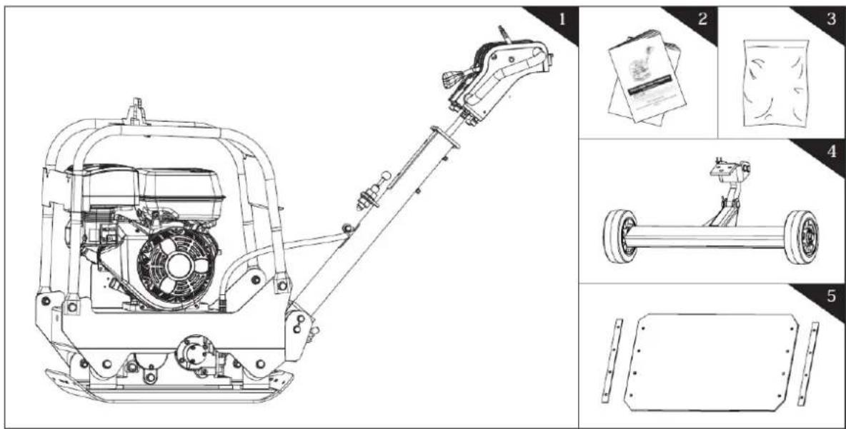
-
Plate Compactor
-
Operator's Manual & Engine Manual
- Hardware Bag, including

- Adjustable Wheels Kit (Optional)
- Paving Pad Kit (Optional)
5.2. Assembly
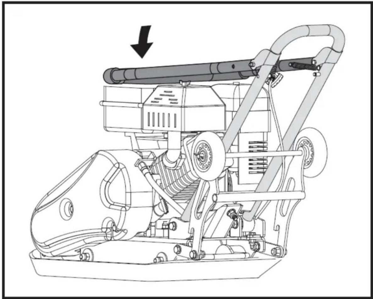
5.2.1. Handle
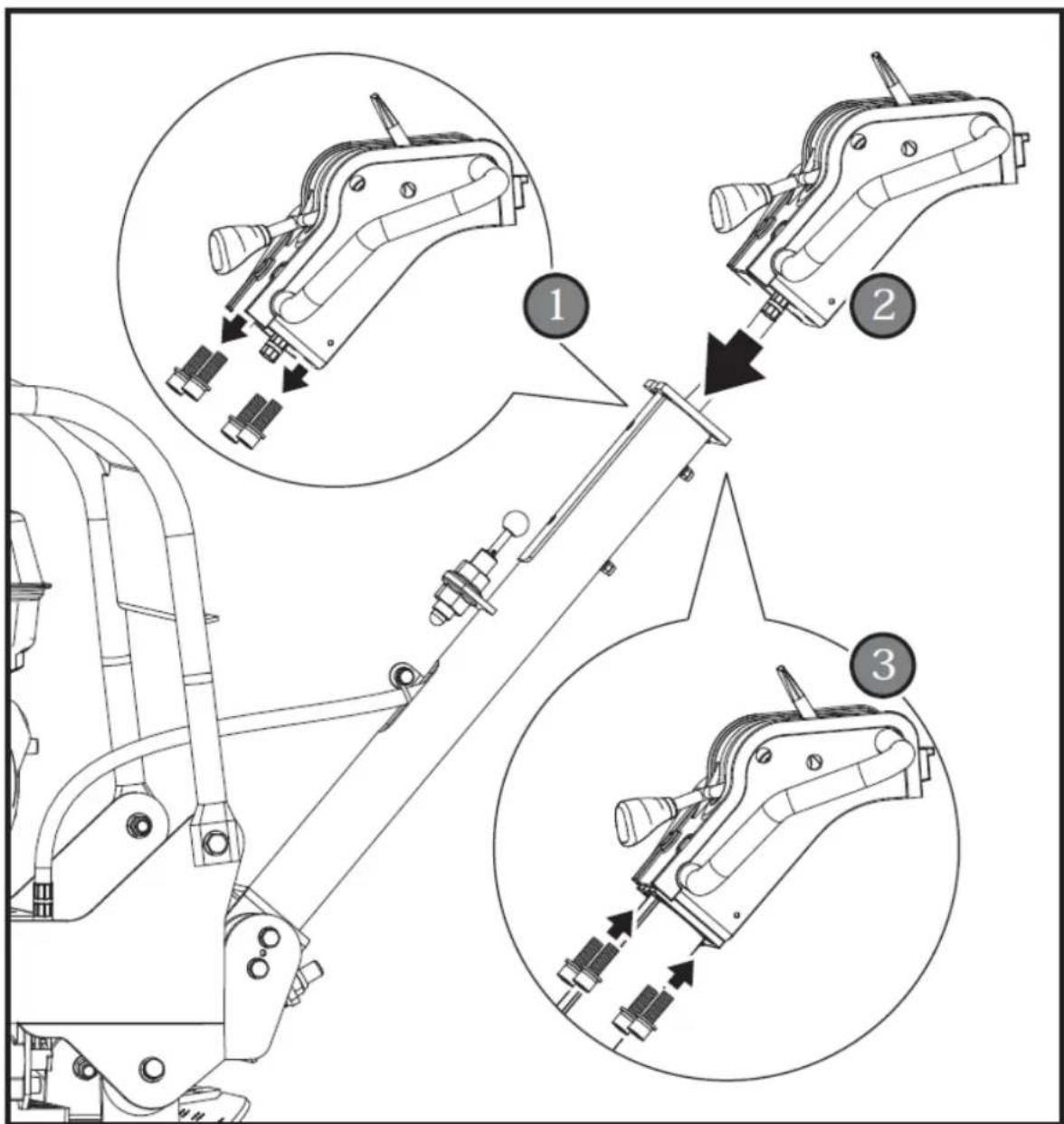
Remove the four M10x25 screws, spring washers and flat washers from the handle-control weldment. Align the four holes in handle tube with the holes in handle-control weldment and secure with M10x25 screws, spring washers and flat washers.
5.2.2. Adjustable Wheels Kit (Optional)
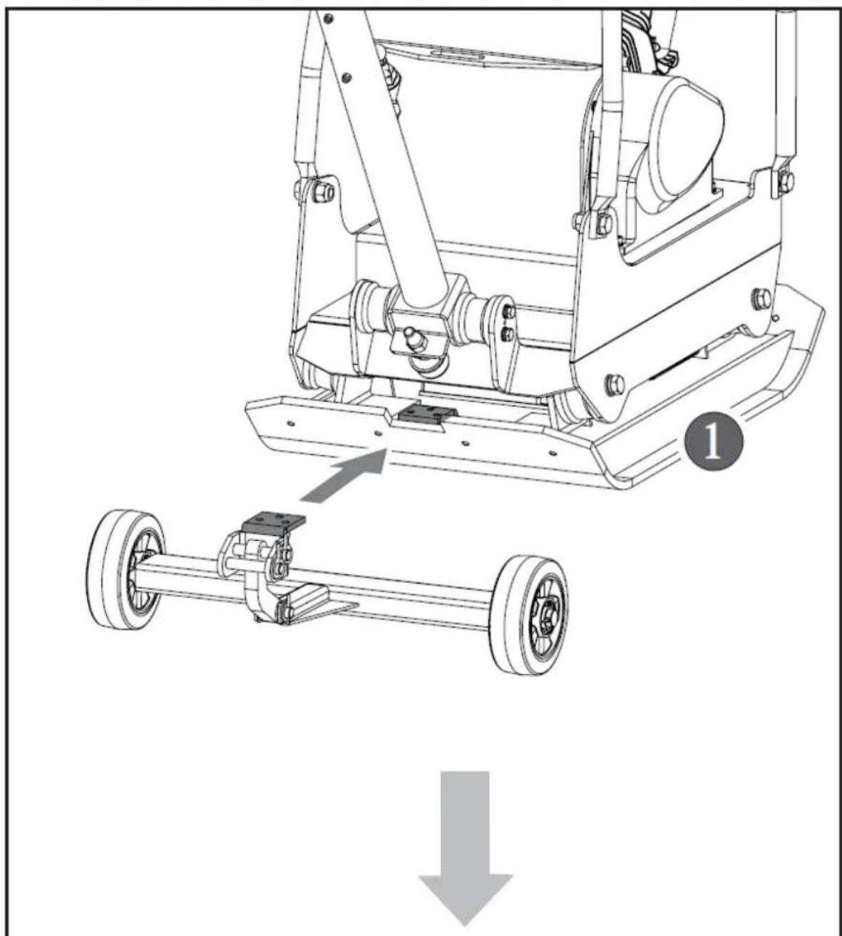

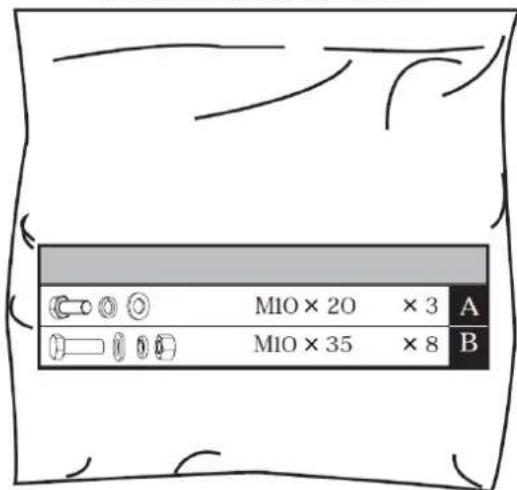
Attach the pre-assembled wheel kit to plate compactor using M10x20 hex bolts, spring washers and flat washers.
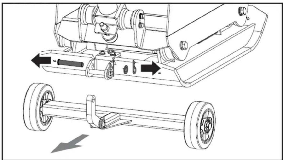
natural_image
Technical line drawing of a mechanical assembly with two views: top shows internal components, bottom shows wheel wheels (no text or symbols)Before compacting, remove the wheel kit as shown.
5.2.3. Paving Pad Kit (Optional)
The transparent rubber paving pad allows to compact concrete slabs, stones, bricks and blocks silently and gently.

Attach the paving pad onto the base plate as shown. Align the holes in the base plate, paving pad and clamp plate, and secure it with M10x35 bolts, spring washers and flat washers.
5.2.4. Engine Oil
Oil has been drained for shipping. Failure to fill engine sump with oil before starting engine will result in permanent damage and will void engine warranty.
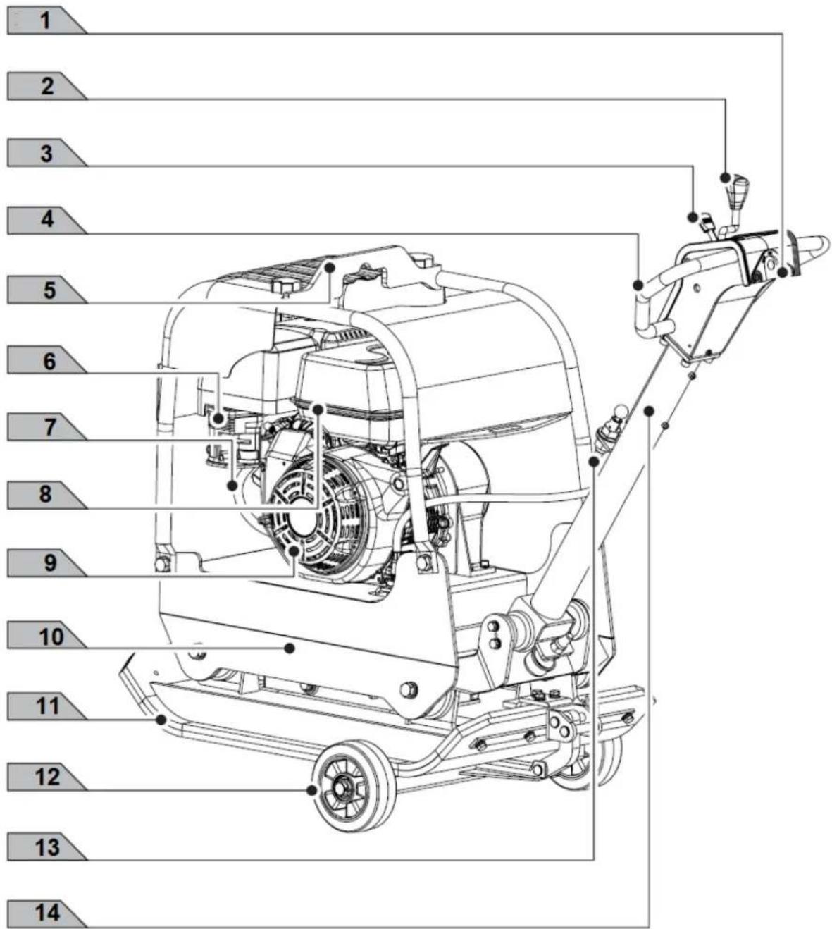
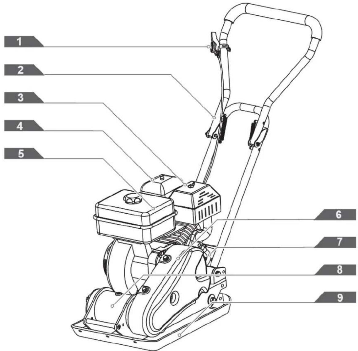
-
Engine Switch
-
Shift Stick
-
Throttle Control
-
Hand Grip
-
Lift Point
-
Air Cleaner
-
Oil Drain Hose
-
Fuel Tank
-
Engine
-
Exciter
-
Base Plate
-
Adjustable Wheel Kit
-
Handlebar Latch Pin
-
Handlebar
Hand Grip
When operating the compactor, use this hand grip to manoeuvre the compactor.
Shift Stick
Push the stick forward, the compactor will move in a forward direction. Pull the stick backwards, the compactor will move in reverse direction. Placing the stick in the middle will cause the compactor not to move (neutral).
Throttle Control
The throttle lever controls engine speed. Moving the throttle lever in the directions shown makes the engine run faster or slower.
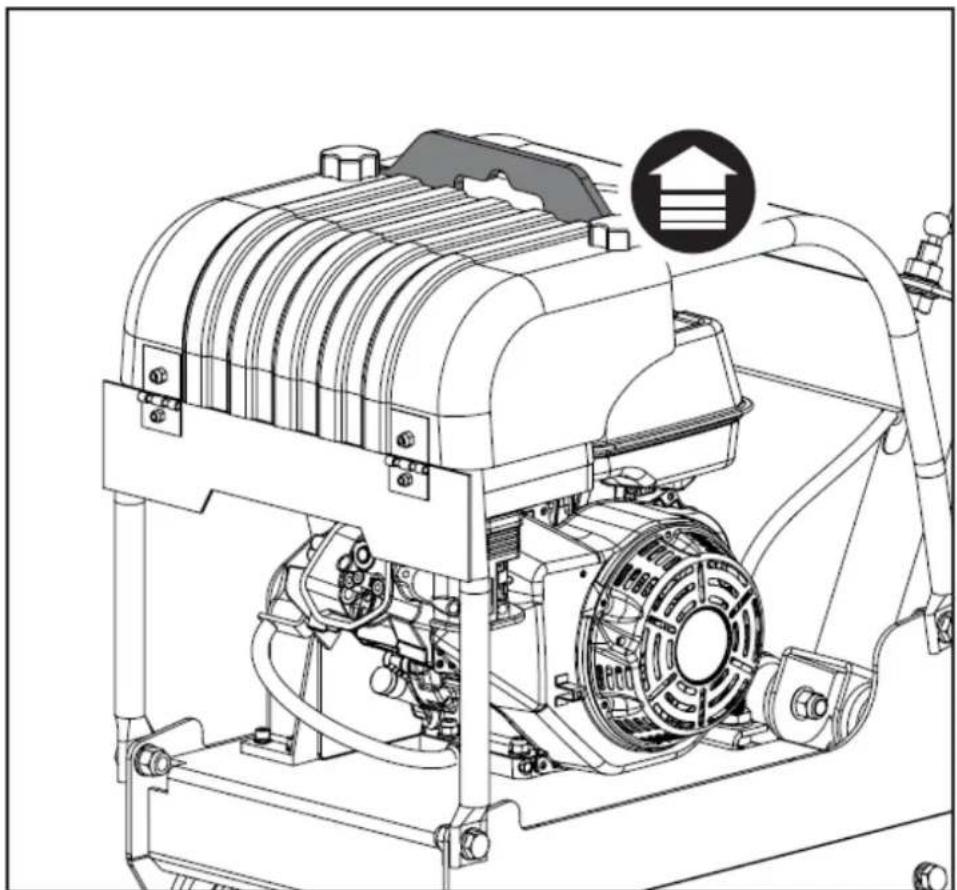
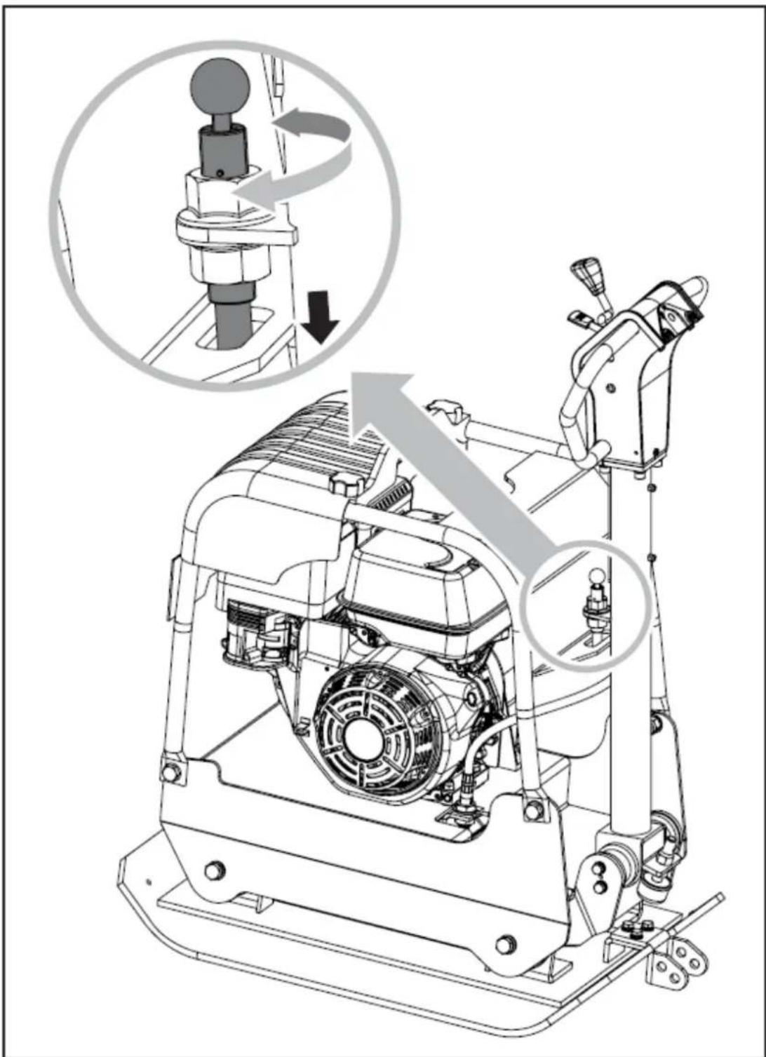
Handlebar
When operating the compactor, this handle is to be in the downward position. When the compactor is to be stored, move the handlebar to the upright position.
Handlebar Latch Pin
Used to lock the handlebar in place in the upward position for transporting and stowing.
Lift Point
Used to lift the machine with crane or other lifting device.
Belt Guard
Remove this guard to gain access to the V-belt. Never run the compactor without the V-belt guard. If the V-belt guard is not installed, the possibility exists that your hand may get caught between the V-belt and clutch, thus causing serious injury and bodily harm.
Exciter
The eccentric shaft contained within exciter housing is driven at high speed by a clutch and belt drive system. This high speed shaft revolution causes the rapid lifting and downward ramming motion of the machine as well as imparting a forward motion.
Engine switch
The engine switch enables and disables the ignition system.
The engine switch must be in the ON position for the engine to run.
Turning the engine switch to the OFF position stops the engine.
Oil Drain Hose
Running the engine with dirty oil can cause premature engine wear and failure. Changing oil regularly is extremely important. The flexible oil drain hose is equipped to drain oil into appropriate receptacle.
5.3. Operation
5.3.1. Adding fuel
Fill the fuel tank as instructed in the separate Engine Manual packed with the plate compactor. A more detailed description of the engine operation and all related precautions and procedures can be found in the Engine Manual packed separately with the unit.
5.3.2. Starting Engine
Move the fuel valve lever to the ON position.
To start a cold engine, move the choke to the CLOSE position.
To restart a warm engine, leave the choke lever in the OPEN position.
Move the throttle lever away from the SLOW position, about 1/3 of the way toward the FAST position.
Place the shift stick in the neutral position.
Turn the engine switch to the ON position.
Operate the starter.
Recoil starter
Pull the starter grip lightly until you feel resistance, then pull briskly, return the starter grip gently. If the choke lever has been moved to the CLOSE position to start the engine, gradually move it to the OPEN position as the engine warms up. After engine warms up, pull throttle lever to accelerate engine speed and place the shift stick at the desired position. Plate will begin vibrating and proceed with compacting.
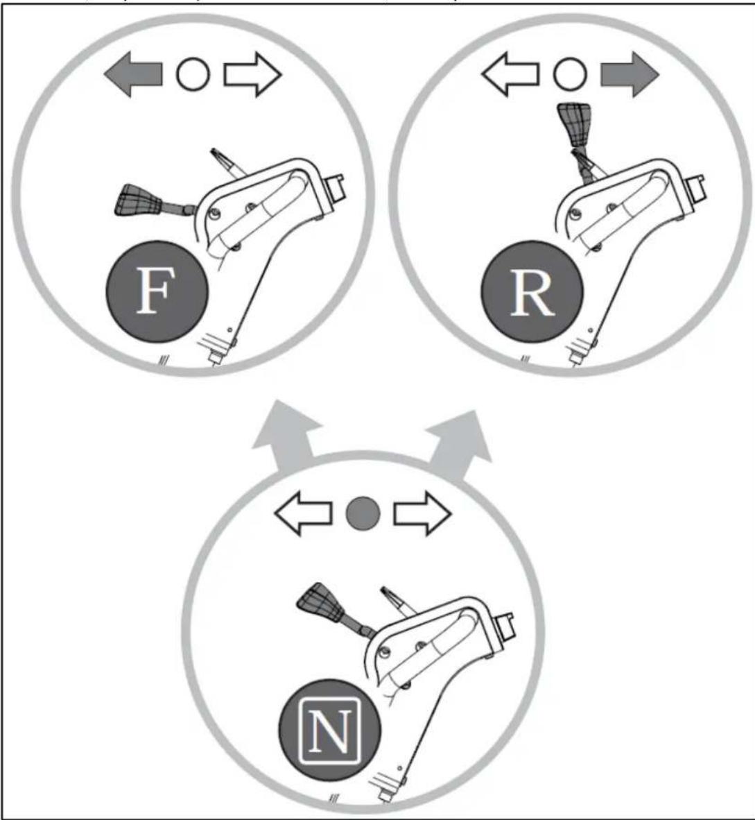
Forward and reverse motion
The direction of travel is determined with the operating control shifter. Depending on the position of the control shifter, the plate compacts in forward direction, on the spot or in reverse direction.
flowchart
graph TD
    A["Left Mechanism F"] --> B["Right Mechanism R"]
    C["Left Mechanism N"] --> D["Right Mechanism N"]
    style A fill:#f9f,stroke:#333
    style C fill:#bbf,stroke:#333
    style B fill:#dfd,stroke:#333
    style D fill:#dfd,stroke:#333
F-FORWARD
R - REVERSE
N - NEUTRAL
To make the compactor move in the forward direction, push the shift stick forward. If shift stick is placed in the neutral position, the compactor will vibrate on the spot. To make the compactor move in the reverse direction, pull the shift stick backwards.
5.3.3. Compaction
Do not operate plate on concrete or on extremely hard, dry, compacted surfaces. The plate will jump rather than vibrate and could damage both plate and engine.
The number of passes required to reach a desired compaction level will depend on the type and moisture content of soil. Maximum soil compaction has been reached when excessive kickback is noticed.
When traveling backwards, the operator has to guide the vibration plate laterally by its guide handle so that you will not be squeezed between the handle and a possible obstacle. Special care is required when
working on uneven ground or when compacting coarse material. Make sure of a firm stand when operating the machine under such conditions.
In operation, guide the machine, but let the compactor do the work. Bearing down on the handle is unnecessary and causes shock absorber wear.
On level surface, the compactor moves forward rapidly. On uneven surfaces or inclines, light forward pressure on handle may be required to assist the compactor in moving forward.
When using plate on paving stones, attach a pad to the bottom of the plate to prevent chipping or grinding surface of the stones. A special urethane pad designed for this purpose is available as an optional accessory.
While a certain amount of moisture in the soil is necessary, excessive moisture may cause soil particles to stick together and prevent good compaction. If soil is extremely wet, allow it to dry somewhat before compacting.
If soil is so dry as to create dust clouds while operating plate, some moisture should be added to the ground material to improve compacting. This will also reduce service to the air filter.
The following points are to be observed when compacting on sloped surfaces (slopes, embankments):
- Only approach gradients from the bottom (a gradient which can be easily overcome upwards can also be compacted downwards without any risk).
- The operator must never stand in the direction of descent.
- The max. gradient of 20^ must not be exceeded.
If this gradient were exceeded, this would result in a failure of the engine lubrication system (splash lubrication) and thus inevitably lead to a breakdown of important engine components.
Stopping engine
To stop the engine in an emergency, simply turn the engine switch to the OFF position. Under normal conditions, use the following procedure.
- To stop the compactor from traveling, return the engine throttle lever to idle position.
- Allow engine to cool down for one or two minutes before stopping.
- Turn the engine switch to "OFF" position.
- Turn off the fuel valve where applicable.
Do not move choke control to CLOSE to stop engine. Backfire or engine damage may occur.
Idle Speed
Set throttle control lever to its SLOW position to reduce stress on the engine when compacting is not being performed. Lowering the engine speed to idle the engine will help extend the life of the engine, as well as conserve fuel and reduce the noise level of the machine.
5.4. Maintenance
5.4.1. Preventive Maintenance
- Turn off engine. Engine must be cool.
- Keep the engine's throttle lever in its SLOW position, and remove spark plug wire from spark plug and secure.
- Inspect the general condition of the plate compactor. Check for loose screws, misalignment or binding of moving parts, cracked or broken parts, and any other condition that may affect its safe operation.
- Remove all debris from the plate compactor with a soft brush, vacuum, or compressed air. Then use a premium quality lightweight machine oil to lubricate all moving parts.
-
Clean the bottom of the compactor base as soon as it begins to pick up soil being compacted. The unit can not do a good job if the bottom surface is not smooth and clean.
-
Replace spark plug wire.
Never use a “pressure washer” to clean your plate compactor. Water can penetrate tight areas of the unit and cause damage to spindles, pulleys, bearings, or the engine. The use of pressure washers will result in shortened life and reduce serviceability.
5.4.2. Checking V-belt
To ensure optimum power transmission from the engine to the eccentric shaft, the V-belt must be in good condition.
-
Turn off engine. Engine must be cool.
-
Remove the belt guard to access the V-belt.
-
Check the condition of the V-belt. If any V-belt is cracked, frayed, or glazed, it should be replaced as soon as convenient.
5.4.3. Replacing V-belt
- Remove the four bolts securing the belt guard.
- Release the spring from tension pulley hook to void the belt tension.
- Slip the old V-belt off the wheel pulley and install the new V-belt in its place.
As the clearance between exciter pulley and engine deck is small, a spark plug sleeve is helpful for installing the new V-belt.
- Position the V-belt over the engine pulley and tension pulley.
- Hook the released spring securing the tension pulley to its original position and check if the V-belt tension is correct.
- Replace the belt guard.
When removing or installing the drive belt, be careful not to get your fingers caught between the belt and pulley.
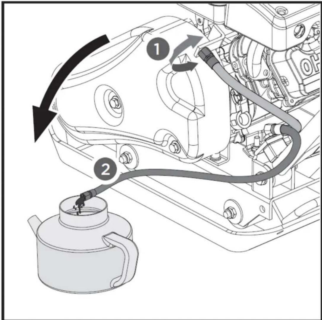
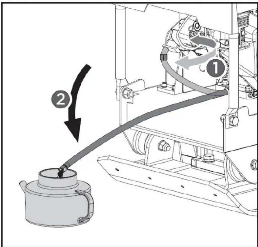
5.4.4. Exciter oil change
The exciter housing is pre-serviced using Automatic Transmission Fluid Dextron III, Mercon, EXXON (ESSO) NUTO H-32 or its equivalent. Change fluid after 200 hours of operation.
- Let exciter cool before changing exciter oil.
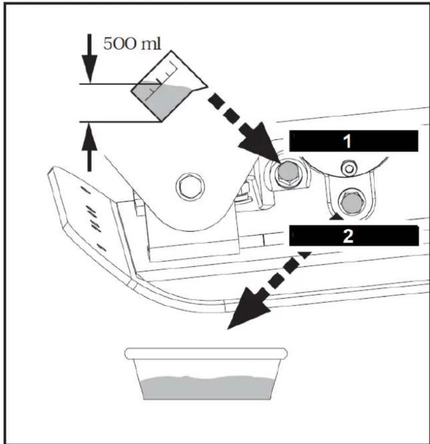
1 - Oil filler plug
2 - Oil drain plug
- Tilt the plate toward a drain pan to aid in the removal of all used oil and particles.
- Remove oil drain plug to drain oil from the exciter assembly. Examine oil for metal chips as a precaution to future problems.
- After oil has been completely drained from the machine, reinstall drain plug.
- Return plate housing to the upright position.
- Add the exciter housing with exciter oil through filler plug opening.
Do not overfill – overfilling can result in excessive temperatures in the exciter. - Apply sealant to filler plug and reinstall it.
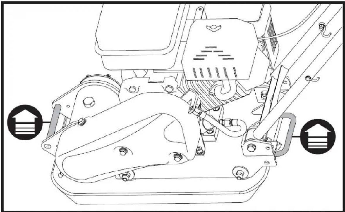
5.4.5. Lifting / Transport
To avoid burns or fire hazards, let engine cool before lifting/transporting machine or storing indoors.
natural_image
Technical line drawing of a mechanical pump or motor assembly (no text or symbols visible)Lift unit by lift hook on roll cage.
Use a reliable chain, cable or strap of adequate lifting capacity.
The unit must be transported in the upright position to prevent fuel from spilling. Do not lay machine on its side or top.
Latch the handlebar in place with the lock pin during lifting/transporting.
Secure or tie down unit using lift hook or roll cage when transporting.
Machine may fall and cause damage or injury if lifted incorrectly. Lift by lift hook only.
5.4.6. Storage
If the plate compactor will not be used for a period longer than 30 days, follow the steps below to prepare your unit for storage.
- Drain the fuel tank completely. Stored fuel containing ethanol or MTBE can start to go stale in 30 days. Stale fuel has high gum content and can clog the carburettor and restrict fuel flow.
- Start the engine and allow it to run until it stops. This ensures no fuel is left in the carburettor. Run the engine until it stops. This helps prevent deposits from forming inside the carburettor and possible engine damage.
- While the engine is still warm, drain the oil from the engine. Refill with fresh oil of the grade recommended in the Engine Manual.
- Allow the engine to cool. Remove the spark plug and put 60 ml of SAE-30 of high quality engine oil into the cylinder. Pull the starter rope slowly to distribute the oil. Replace the spark plug.
Remove the spark plug and drain all of the oil from the cylinder before attempting to start the unit after storage.
- Use clean cloths to clean off the outside of the compactor and to keep the air vents free of obstructions.
Do not use strong detergents or petroleum based cleaners when cleaning plastic parts. Chemicals can damage plastics.
- Secure the handle with the lock pin as shown.
- Store your plate compactor in upright position in a clean, dry building that has good ventilation.
Do not store compactor with fuel in a non-ventilated area where fuel fumes may reach flame, sparks, pilot lights or any ignition sources.
Use only approved fuel containers.
6. Troubleshooting
| Problem | Cause | Remedy |
| Engine fails to start. | 1. Spark plug wire disconnected.2. Out of fuel or stale fuel.3. Throttle control lever not in correct starting position.4. Choke not in ON Position.5. Blocked fuel line.6. Fouled spark plug.7. Engine flooding. | 1. Attach spark plug wire securely to spark plug.2. Fill with clean, fresh gasoline.3. Move throttle control lever to start position.4. Throttle must be positioned at choke for a cold start.5. Clean the fuel line.6. Clean, adjust gap, or replace.7. Wait a few minutes to restart, but do not prime. |
| Engine runs erratically. | 1. Spark plug wire loose.2. Unit running on CHOKE.3. Blocked fuel line or stale fuel.4. Vent plugged.5. Water or dirt in fuel system.6. Dirty air cleaner. | 1. Connect and tighten spark plug wire.2. Move choke lever to OFF.3. Clean fuel line. Fill tank with clean, fresh gasoline.4. Clear vent.5. Drain fuel tank. Refill with fresh fuel.6. Clean or replace air cleaner. |
| Engine overheats. | 1. Engine oil level low.2. Dirty air cleaner.3. Air flow restricted. | 1. Fill crankcase with proper oil.2. Clean air cleaner.3. Remove blower housing and clean. |
| Engine will not stop when throttle control is positioned at stop, or engine speed does not increase properly when throttle control is adjusted. | Debris interfering with throttle linkage. | Clean dirt and debris. |
| Compactor is difficult to control when pounding (machine jumps or lurches forward) | Too high engine speed on hard ground. | Set the throttle lever at lower speed. |
DISPOSING OF USED DEVICES:
Do not dispose of this device in municipal waste systems. Hand it over to an electric and electrical device recycling and collection point. Check the symbol on the product, instruction manual and packaging. The plastics used to construct the device can be recycled in accordance with their markings. By choosing to recycle you are making a significant contribution to the protection of our environment.
Contact local authorities for information on your local recycling facility.

natural_image
Technical line drawing of a mechanical device with two views: top shows internal components, bottom shows external housing (no text or symbols)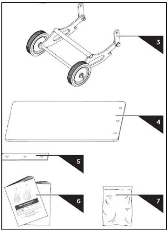
natural_image
Diagram of a mechanical device with a handle and scroll, showing a left-hand rule and an arrow indicating motion (no text or symbols present)natural_image
Technical diagram of an electric motor assembly with mounting base and housing (no text or labels)natural_image
Technical line drawing of a mechanical pump assembly with a container filled with granular material (no text or symbols)natural_image
Technical line drawing of a mechanical assembly with no visible text or symbolsnatural_image
Technical line drawing of a mechanical pump assembly with no visible text or symbols1 - Zageszczarka
2 - Instrukcja

natural_image
Technical line drawing of a mechanical assembly with two views: top shows internal components, bottom shows wheel wheels (no text or symbols)natural_image
Technical line drawing of a mechanical pump or motor assembly (no text or symbols visible)natural_image
Technical line drawing of a mechanical device with two views: top shows internal components, bottom shows external housing (no text or symbols)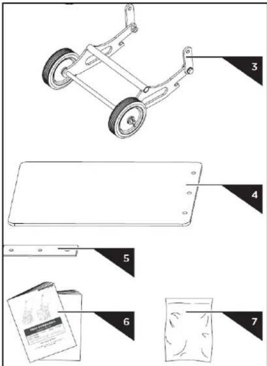
4.2. Montáž
natural_image
Diagram of a manual lift or lever mechanism with a curved handle and spring-loaded base, showing motion direction (no text or symbols)1 - Upínací deska
natural_image
Technical diagram of an electric motor assembly with mounting base and housing (no text or labels)natural_image
Technical line drawing of a mechanical pump assembly with a container filled with granular material (no text or symbols)natural_image
Technical line drawing of a mechanical assembly with no visible text or symbolsnatural_image
Technical line drawing of a mechanical device with no visible text or symbols
natural_image
Technical line drawing of a mechanical assembly with two views: top shows internal components, bottom shows wheel wheels (no text or symbols)F - VPŘED
R - REVERSE
N - NEUTRÁLNÍ
natural_image
Technical line drawing of a mechanical pump or motor assembly (no text or symbols visible)natural_image
Technical line drawing of a mechanical device with two views (labeled 1 and 2), showing internal components without any text or symbols.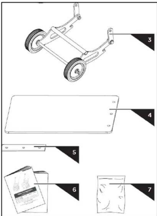
4.2. Montage
natural_image
Diagram of a manual push-button device with a handle and scroll, showing motion direction (no text or symbols)natural_image
Technical line drawing of a manual lawn mower with labeled components (no text or symbols present)| M10 × 30 (#29140-V) × 2 | |
| M10 × 20 (#29142-V) × 3 | |
| M10 × 25 (#29155-V) × 2 | |
| M10 × 30 (#29160-V, #29165-V) × 3 |
natural_image
Technical diagram of an electric motor assembly with mounting base and housing (no text or labels)natural_image
Technical line drawing of a mechanical pump assembly with a container filled with granular material (no text or symbols)natural_image
Technical line drawing of a mechanical assembly with no visible text or symbolsnatural_image
Technical line drawing of a mechanical device with no visible text or symbols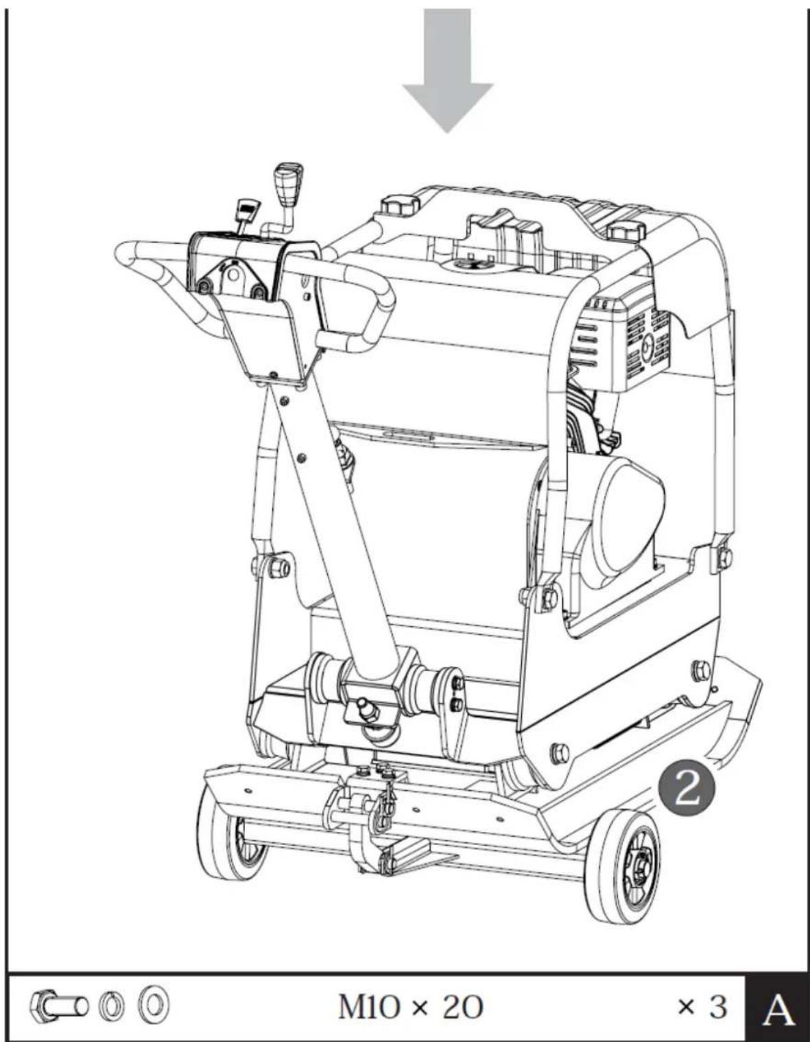
natural_image
Technical line drawing of a mechanical assembly with two views: top shows internal components, bottom shows wheel wheels (no text or symbols)natural_image
Technical line drawing of a mechanical pump or motor assembly (no text or symbols visible)natural_image
Technical line drawing of a mechanical device with two views: top shows top view, bottom shows side view (no text or symbols)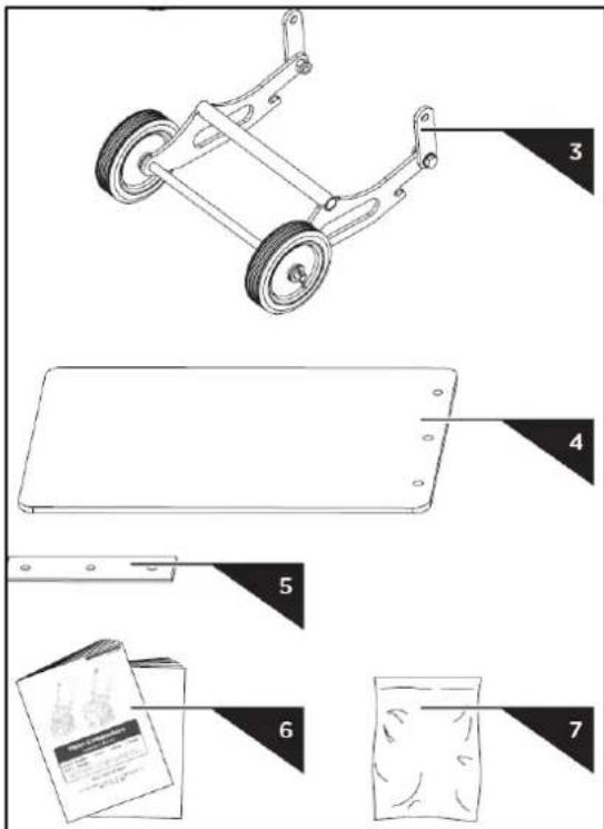
natural_image
Diagram of a mechanical device with a handle and scroll, showing a right-hand rule for motion (no text or symbols present)natural_image
Technical diagram of an electric motor assembly with mounting base and housing (no text or labels)natural_image
Technical line drawing of a mechanical pump assembly with a container filled with granular material (no text or symbols)natural_image
Technical line drawing of a mechanical assembly with no visible text or symbolsnatural_image
Technical line drawing of a mechanical pump assembly with no visible text or symbols
natural_image
Technical line drawing of a mechanical assembly with two views: top shows internal components, bottom shows wheel wheels (no text or symbols)natural_image
Technical line drawing of a mechanical pump or motor assembly (no text or symbols visible)natural_image
Technical line drawing of a mechanical device with two views: top shows top view, bottom shows side view (no text or symbols)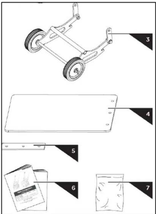
4.2. Montaje
4.2.1. Asa superior

natural_image
Diagram of a manual push-button device with a handle and scroll, showing motion direction (no text or symbols)natural_image
Technical diagram of an electric motor assembly with mounting base and housing (no text or labels)natural_image
Technical line drawing of a mechanical pump assembly with a container filled with granular material (no text or symbols)natural_image
Technical line drawing of a mechanical assembly with no visible text or symbolsnatural_image
Technical line drawing of a mechanical pump assembly with no visible text or symbols
natural_image
Technical line drawing of a mechanical assembly with two views: top shows internal components, bottom shows wheel wheels (no text or symbols)natural_image
Technical line drawing of a mechanical pump or motor assembly (no text or symbols visible)natural_image
Technical line drawing of a mechanical device with two views: top shows internal components, bottom shows external housing (no text or symbols)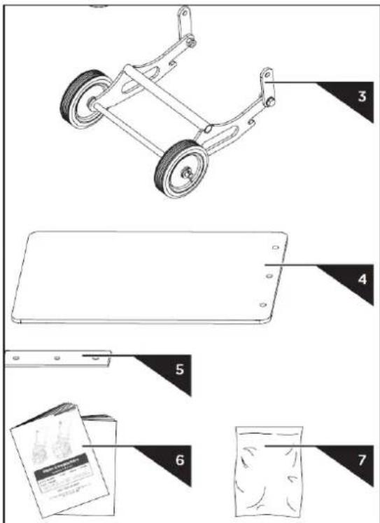
4.2. Felszerelés
natural_image
Diagram of a manual push-button device with a handle and scroll, showing motion direction (no text or symbols)1 - Rögzítőlemez
natural_image
Technical diagram of an electric motor assembly with mounting base and housing (no text or labels)natural_image
Technical line drawing of a mechanical pump assembly with a container filled with granular material (no text or symbols)natural_image
Technical line drawing of a mechanical assembly with no visible text or symbolsnatural_image
Technical line drawing of a mechanical pump assembly with no visible text or symbols
natural_image
Technical line drawing of a mechanical assembly with two views: top shows internal components, bottom shows wheel wheels (no text or symbols)natural_image
Technical line drawing of a mechanical pump or motor assembly (no text or symbols visible)OBS! Giftige stoffer, fare for forgiftning!

natural_image
Technical line drawing of a mechanical device with two views (labeled 1 and 2), showing internal components and assembly (no text or symbols present)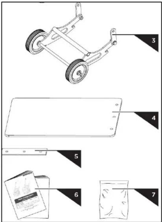
1 - Klemmeplade
natural_image
Technical diagram of a mechanical assembly with labeled parts, showing motor, gear, and housing components (no text or symbols present)natural_image
Technical line drawing of a mechanical device with a funnel inserted into a tray (no text or symbols)natural_image
Technical line drawing of a mechanical assembly with no visible text or symbolsnatural_image
Technical line drawing of a mechanical pump assembly with no visible text or symbols-
Pladekomprimator
-
Brugsanvisning og motormanual
-
Hardwarepose, inklusive


natural_image
Technical line drawing of a mechanical assembly with two views: top shows internal components, bottom shows wheel wheels (no text or symbols)natural_image
Technical line drawing of a mechanical pump or motor assembly (no text or symbols visible)natural_image
Technical line drawing of a mechanical device with two views: top shows internal components, bottom shows external housing (no text or symbols)
4.2. Kokoonpano
4.2.1. Yläkahva

natural_image
Diagram of a manual push-button mechanism with a curved handle and scroll, showing motion direction (no text or symbols)1 - Kiinnityslevy
natural_image
Technical diagram of a mechanical assembly with labeled parts, showing motor, gear, and housing components (no text or symbols present)natural_image
Technical line drawing of a mechanical pump assembly with a container filled with granular material (no text or symbols)natural_image
Technical line drawing of a mechanical assembly with no visible text or symbolsnatural_image
Technical line drawing of a mechanical device with no visible text or symbols
natural_image
Technical line drawing of a mechanical assembly with two views: top shows internal components, bottom shows wheel wheels (no text or symbols)natural_image
Technical line drawing of a mechanical pump or motor assembly (no text or symbols visible)natural_image
Technical line drawing of a mechanical device with two views (labeled 1 and 2), showing internal components and assembly (no text or symbols present)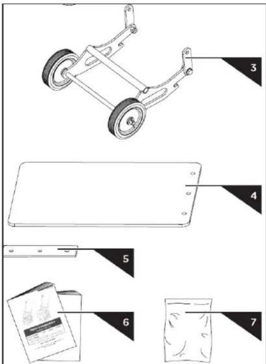
| M10 × 30 | ×2 | |
| M10 × 30 (#29140-V) | ×2 | |
| M10 × 20 (#29142-V) | ×3 | |
| M10 × 25 (#29155-V) | ×2 | |
| M10 × 30 (#29160-V, #29165-V) | ×3 |
4.2. Montage
4.2.1. Bovenste handgreep
natural_image
Diagram of a mechanical device with a handle and scroll, showing a left-hand rule and an arrow indicating motion (no text or symbols present)natural_image
Technical line drawing of a manual lawn mower with labeled components (no text or symbols present)| M10 × 30 (#29140-V) × 2 | |
| M10 × 20 (#29142-V) × 3 | |
| M10 × 25 (#29155-V) × 2 | |
| M10 × 30 (#29160-V, #29165-V) × 3 |
1 - Klemplaat
natural_image
Technical diagram of an electric motor assembly with mounting base and housing (no text or labels)natural_image
Technical line drawing of a mechanical pump assembly with a container filled with granular material (no text or symbols)natural_image
Technical line drawing of a mechanical assembly with no visible text or symbolsnatural_image
Technical line drawing of a mechanical pump assembly with no visible text or symbols
natural_image
Technical line drawing of a mechanical assembly with two views: top shows internal components, bottom shows wheel wheels (no text or symbols)natural_image
Technical line drawing of a mechanical pump or motor assembly (no text or symbols visible)OBS! Varm overflate, fare for forbrenning!

natural_image
Technical line drawing of a mechanical device with two views: top shows internal components, bottom shows external housing (no text or symbols)
4.2. montering
4.2.1. ∅vre håndtak

natural_image
Diagram of a manual lift or lever mechanism with a curved handle and spring-loaded base, showing motion direction (no text or symbols)Før du komprimerer, brett opp hjulsettet som vist.
4.2.4. Paving Pad Kit (valgfritt)
1 - Klemplate
natural_image
Technical diagram of a mechanical assembly with labeled parts, showing motor, gear, and housing components (no text or symbols present)natural_image
Technical line drawing of a mechanical pump assembly with a container filled with granular material (no text or symbols)natural_image
Technical line drawing of a mechanical assembly with no visible text or symbolsnatural_image
Technical line drawing of a mechanical pump assembly with no visible text or symbols
natural_image
Technical line drawing of a mechanical assembly with two views: top shows internal components, bottom shows wheel wheels (no text or symbols)-
Motorbryter
-
Shift Stick
-
Gasskontroll
-
Håndgrep
-
Løftepunkt
-
Luftrenser
-
Oljeavløpsslange
-
Bensintank
-
Motor
-
Exciter
-
Grunnplate
-
Justerbart hjulsett
-
Styre läsepinne
-
Styre
Håndgrep
natural_image
Technical line drawing of a mechanical pump or motor assembly (no text or symbols visible)Lås styret på plass med läsepinnen under løfting/transport.
Fest eller fest enheten ved hjelp av løftekrok eller rullebur under transport.
Maskinen kan falle og forårsake skade eller personskade hvis den løftes feil. Løft kun med løftekrok.
5.4.6. Oppbevaring
natural_image
Technical line drawing of a mechanical device with two views (labeled 1 and 2), showing internal components and assembly (no text or symbols present)
1 - Klämplatta
natural_image
Technical line drawing of a mechanical pump assembly with a container filled with granular material (no text or symbols)natural_image
Technical line drawing of a mechanical assembly with no visible text or symbolsnatural_image
Technical line drawing of a mechanical pump assembly with no visible text or symbols
natural_image
Technical line drawing of a mechanical assembly with two views: top shows internal components, bottom shows wheel wheels (no text or symbols)-
Motorströmbrytare
-
Shift Stick
-
Gasreglage
-
Handgrepp
-
Lyftpunkt
-
Luftrenare
-
Oljeavloppsslang
-
Bränsletank
-
Motor
-
Exciter
-
Basplatta
-
Justerbar hjulsats
-
Styrets spärrstift
-
Styre
Handgrepp
natural_image
Technical line drawing of a mechanical pump or motor assembly (no text or symbols visible)natural_image
Technical line drawing of a mechanical device with two views (labeled 1 and 2), showing internal components without any text or symbols.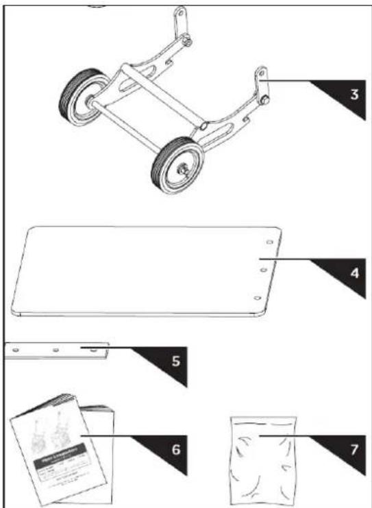
4.2. Conjunto
4.2.1. Alça superior

natural_image
Diagram of a mechanical device with a handle and scroll, showing a right-hand rule for motion (no text or symbols present)Desdobre a alça conforme mostrado.
4.2.2. Pega

Antes de compactar, dobre o kit de rodas conforme mostrado.
natural_image
Technical line drawing of a manual lawn mower with labeled components (no text or symbols present)| M10 × 30 (#29140-V) × 2 | |
| M10 × 20 (#29142-V) × 3 | |
| M10 × 25 (#29155-V) × 2 | |
| M10 × 30 (#29160-V, #29165-V) × 3 |
natural_image
Technical diagram of an electric motor assembly with mounting base and housing (no text or labels)natural_image
Technical line drawing of a mechanical pump assembly with a container filled with granular material (no text or symbols)natural_image
Technical line drawing of a mechanical assembly with no visible text or symbolsnatural_image
Technical line drawing of a mechanical excavator assembly with no visible text or symbols-
Compactador de Placa
-
Manual do Operador e Manual do Motor
-
Bolsa de ferragens, incluindo

natural_image
Technical line drawing of a mechanical assembly with two views: top shows internal components, bottom shows wheel wheels (no text or symbols)Antes de compactar, remova o kit de rodas conforme mostrado.
natural_image
Technical line drawing of a mechanical pump or motor assembly (no text or symbols visible)natural_image
Technical line drawing of a mechanical device with two views (labeled 1 and 2), showing internal components without any text or symbols.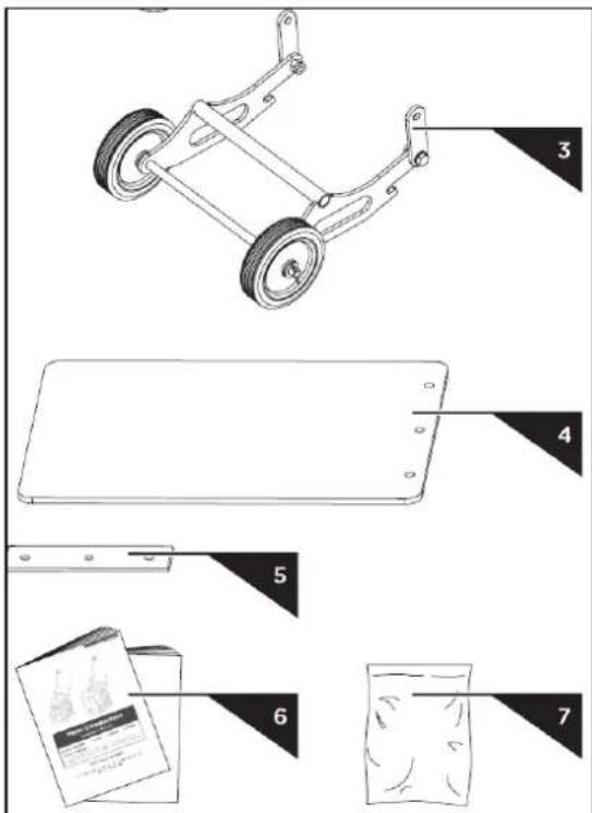
- Šasi doskového zhutňovača s motorom a prevodovkou
- Rukovät
- Súprava skladacích kolies (voliteľné)
- Dlažobná podložka (volitel'né)
- Upínacia doska (volitel'né)
- Návod na obsluhu a manuál motora
- Taška na hardvér, vrátane:

4.2. zhromaždenie
natural_image
Diagram of a manual lift or lever mechanism with a curved handle and spring, showing motion direction (no text or symbols)natural_image
Technical diagram of a mechanical assembly with labeled parts, showing motor, gear, and housing components (no text or symbols present)natural_image
Technical line drawing of a mechanical pump assembly with a container filled with granular material (no text or symbols)natural_image
Technical line drawing of a mechanical assembly with no visible text or symbolsnatural_image
Technical line drawing of a mechanical pump assembly with no visible text or symbols
natural_image
Technical line drawing of a mechanical assembly with two views: top shows internal components, bottom shows wheel wheels (no text or symbols)natural_image
Technical line drawing of a mechanical device with internal components and mounting brackets (no text or symbols)For the disposal of the device please consider and act according to the national and local rules and regulations.
CONTACT
expondo Polska sp. z o.o. sp. k.