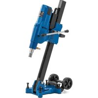
DDM-A4250S - Drill MSW - Free user manual and instructions
Find the device manual for free DDM-A4250S MSW in PDF.


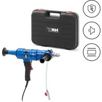
| Product type | Diamond core drill |
| Brand | MSW |
| Model | DDM-A4250S |
| Rated voltage | 230 V~ |
| Frequency | 50 Hz |
| Rated power | 3300 W |
| Maximum drilling diameter | 255 mm |
| Drilling diameter at gear 1/2/3 | 155 mm |
| Core bit mounting diameter | 1 1/4 - 7 UNC G1/2 |
| Guide span adjustment | ≤500 mm |
| Dimensions (L x W x H) | 50 x 25 x 93 cm |
| Weight | 24.1 kg |
| Sound pressure level | 90 dB |
| Sound power level | 103 dB |
| Water connector diameter | 4 inches |
| Water supply required | Yes (wet bits) |
| Compatible materials | Concrete, stone, masonry, pipes |
| Number of speeds | 2 or 3 (depending on model) |
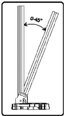
| Angle adjustment | 0° to 45° |
| Recommended personal protection | Helmet, insulating gloves, goggles, dust mask, hearing protection, safety shoes |
| Intended use | Drilling holes for installations of coolers, electrical devices, plumbing |
Frequently Asked Questions - DDM-A4250S MSW
User questions about DDM-A4250S MSW
0 question about this device. Answer the ones you know or ask your own.
Ask a new question about this device
Download the instructions for your Drill in PDF format for free! Find your manual DDM-A4250S - MSW and take your electronic device back in hand. On this page are published all the documents necessary for the use of your device. DDM-A4250S by MSW.
USER MANUAL DDM-A4250S MSW
1 - Schaltkasten
This User Manual has been translated for your convenience using machine translation. Reasonable efforts have been made to provide an accurate translation; however, no automated translation is perfect nor is it intended to replace human translators. The official User Manual is the English version. Any discrepancies or differences created in the translation are not binding and have no legal effect for compliance or enforcement purposes. If any questions arise related to the accuracy of the information contained in the User Manual, please refer to the English version of those contents which is the official version.
Technical data
| Parameter description | Parameter value |
| Product name | Diamond drilling machine |
| Model | MSW-DDM-A4250S |
| Rated voltage [V~] / frequency [Hz] | 230 / 50 |
| Rated power [W] | 3300 |
| Water hose connector diameter [mm] | 10 |
| Core drill mounting diameter ["] | 1 1/4 - 7 UNC G1/2 |
| Drilling diameter on gear 1/2/3 [mm] | 155 |
| Maximum drilling diameter [mm] | 255 |
| Guide reach adjustment [mm] | ≤500 |
| Sound pressure level [dB] | 90 |
| Sound power level [dB] | 103 |
| Water connector diameter ['] | 4 |
| Dimensions [cm] | 50 x 25 x 93 |
| Weight [kg] | 24.1 |
1. General description
The user manual is designed to assist in the safe and trouble-free use of the device. The product is designed and manufactured in accordance with strict technical guidelines, using state-of-the-art technologies and components. Additionally, it is produced in compliance with the most stringent quality standards.
DO NOT USE THE DEVICE UNLESS YOU HAVE THOROUGHLY READ AND UNDERSTOOD THIS USER MANUAL.
To increase the product life of the device and to ensure trouble-free operation, use it in accordance with this user manual and regularly perform maintenance tasks. The technical data and specifications in this user manual are up to date. The manufacturer reserves the right to make changes associated with quality improvement. The device is designed to reduce noise emission risks to a minimum, taking into account technological progress and noise reduction opportunities.
Legend

The product satisfies the relevant safety standards.

Read instructions before use.




The product must be recycled.
WARNING! or CAUTION! or REMEMBER! Applicable to the given situation. (general warning sign)
Use ear protection. Exposure to loud noise may result in hearing loss.
Wear protective goggles.
Wear a dust mask (respiratory tract protection).
Wear protective gloves.
Wear foot protection.
Wear a face shield.
Wear protective clothing.
ATTENTION! Electric shock warning!
ATTENTION! Rotating parts, entanglement hazard!
ATTENTION! Hot surface, risk of burns!

PLEASE NOTE! Drawings in this manual are for illustration purposes only and in some details may differ from the actual product.
2. Usage safety

ATTENTION!
Read all safety warnings and all instructions. Failure to follow the warnings and instructions may result in electric shock, fire and/or serious injury or even death.
The terms "device" or "product" are used in the warnings and instructions to refer to: Diamond drilling machine
2.1. Electrical safety
a) The plug must fit the socket. Do not modify the plug in any way. Using original plugs and matching sockets reduces the risk of electric shock.
b) Avoid touching earthed elements such as pipes, heaters, boilers and refrigerators. There is an increased risk of electric shock if the earthed device is exposed to rain, comes into direct
EN
contact with a wet surface or is operating in a damp environment. Water getting into the device increases the risk of damage to the device and of electric shock.
c) Do not touch the device with wet or damp hands.
d) Use the cable only for its designated use. Never use it to carry the device or to pull the plug out of a socket. Keep the cable away from heat sources, oil, sharp edges or moving parts. Damaged or tangled cables increase the risk of electric shock.
e) If working with the device outdoors, make sure to use an extension cord suitable for outdoor use. Using an extension cord suitable for outdoor use reduces the risk of electric shock.
f) If using the device in a damp environment cannot be avoided, a residual current device (RCD) should be applied. The use of an RCD reduces the risk of electric shock.
g) Do not use the device if the power cord is damaged or shows obvious signs of wear. A damaged power cord should be replaced by a qualified electrician or the manufacturer's service centre.
h) To avoid electric shock, do not immerse the cord, plug or device in water or other liquids. Do not use the device on wet surfaces.
2.2. Safety in the workplace
a) Make sure the workplace is clean and well lit. A messy or poorly lit workplace may lead to accidents. Try to think ahead, observe what is going on and use common sense when working with the device.
b) Do not use the device in a potentially explosive environment, for example in the presence of flammable liquids, gases or dust. The device generates sparks which may ignite dust or fumes.
c) If there are any doubts as to the correct operation of the device, contact the manufacturer's support service.
d) Only the manufacturer's service point may repair the device. Do not attempt any repairs independently!
e) In case of fire, use a powder or carbon dioxide (CO2) fire extinguisher (one intended for use on live electrical devices) to put it out.
f) Children or unauthorised persons are forbidden to enter a work station. (A distraction may result in loss of control over the device).
g) Use the device in a well-ventilated space.
h) The device produces dust and debris during operation. It is important to protect bystanders from their harmful effects.
i) Regularly inspect the condition of the safety labels. If the labels are illegible, they must be replaced.
j) Please keep this manual available for future reference. If this device is passed on to a third party, the manual must be passed on with it.
k) Keep packaging elements and small assembly parts in a place not available to children.
I) Keep the device away from children and animals.
m) If this device is used together with another equipment, the remaining instructions for use shall also be followed.
n) Pay attention to the conditions of working area. Do not expose the device to rain or use it in wet places. Working area should be properly protected, especially checked for the presence of explosive and flammable liquids and gases (sprays, paints, gasoline, solvents, adhesives), which may become the cause of fire or explosion when combined with sparks created by the device. The device must not come in contact with high-voltage lines, gas/water piping, etc. In
order to avoid a collapse, examine workpiece's construction before invading it with the device.

Remember! When using the device, protect children and other bystanders.
2.3. Personal safety
a) Do not use the device when tired, ill or under the influence of alcohol, narcotics or medication which can significantly impair the ability to operate the device.
b) The device is not designed to be handled by persons (including children) with limited mental and sensory functions or persons lacking relevant experience and/or knowledge unless they are supervised by a person responsible for their safety or they have received instruction on how to operate the device.
c) The device can be handled only by physically fit persons who are capable of handling it, properly trained, familiar with this manual and trained within the scope of occupational health and safety.
d) When working with the device, use common sense and stay alert. Temporary loss of concentration while using the device may lead to serious injuries.
e) Use personal protective equipment as required for working with the device, specified in section 1 (Legend). The use of correct and approved personal protective equipment reduces the risk of injury.
f) To prevent the device from accidentally switching on, make sure the switch is on the OFF position before connecting to a power source.
g) Do not overestimate your abilities. When using the device, keep your balance and remain stable at all times. This will ensure better control over the device in unexpected situations.
h) Do not wear loose clothing or jewellery. Keep hair, clothes and gloves away from moving parts. Loose clothing, jewellery or long hair may get caught in moving parts.
i) Remove all adjusting tools or spanners before turning the device on.
j) Use eye, ear and respiratory protection.
k) Use personal protective equipment such as: protective gloves, safety shoes, face shield, protective suit.
I) The device is not a toy. Children must be supervised to ensure that they do not play with the device.
2.4. Safe device use
a) Do not overload the device. Use the appropriate tools for the given task. A correctly-selected device will perform the task for which it was designed better and in a safer manner.
b) Do not use the device if the ON/OFF switch does not function properly (does not switch the device on and off). Devices which cannot be switched on and off using the ON/OFF switch are hazardous, should not be operated and must be repaired.
c) Disconnect the device from the power supply before commencement of adjustment, cleaning and maintenance. Such a preventive measure reduces the risk of accidental activation.
d) When not in use, store in a safe place, away from children and people not familiar with the device who have not read the user manual. The device may pose a hazard in the hands of inexperienced users.
e) Keep the device in perfect technical condition.
f) Keep the device out of the reach of children.
g) Device repair or maintenance should be carried out by qualified persons, only using original spare parts. This will ensure safe use.
h) To ensure the operational integrity of the device, do not remove factory-fitted guards and do not loosen any screws.
i) Do not leave this appliance unattended while it is in use.
j) Do not cover the air intake and outlet.
k) The device is not a toy. Cleaning and maintenance may not be carried out by children without supervision by an adult person.
I) It is forbidden to interfere with the structure of the device in order to change its parameters or construction.
m) Keep the device away from sources of fire and heat.
n) Do not lean out. Stay in a stable position and keep balance during operation.
o) Hold the device firmly. When using hands, hold only handles delivered with the device.
p) Maintain the device and accessories sharp and clean. Follow proper lubrication procedures and replace accessories when necessary. Extension cords should be regularly examined and fixed or replaced when necessary. Handles need to be dry, clean and free from oils and grease all the time.
q) Do not touch moving/rotating elements, unless the device is disconnected from the power supply.
r) Pay particular attention to people and objects below when working at heights.
s) Remember to properly set a working tool in the device.
t) A tool becomes extremely hot during operation of the device.
u) Keep water away from the engine.
v) When moving with the device connected to the power supply, do not keep fingers on the ON/OFF switch. The device can be used only when being held with a handle.
w) The device should be equipped with drill adapters/bits intended to work with water.

ATTENTION! Despite the safe design of the device and its protective features, and despite the use of additional elements protecting the operator, there is still a slight risk of accident or injury when using the device. Stay alert and use common sense when using the device.
3. Use guidelines
This machine is designed for drilling in concrete, stone, masonry, and pipework, making it suitable for installing air coolers, electrical appliances, and plumbing for water and gas pipes.
The user is liable for any damage resulting from unintended use of the device.
3.1. Device description
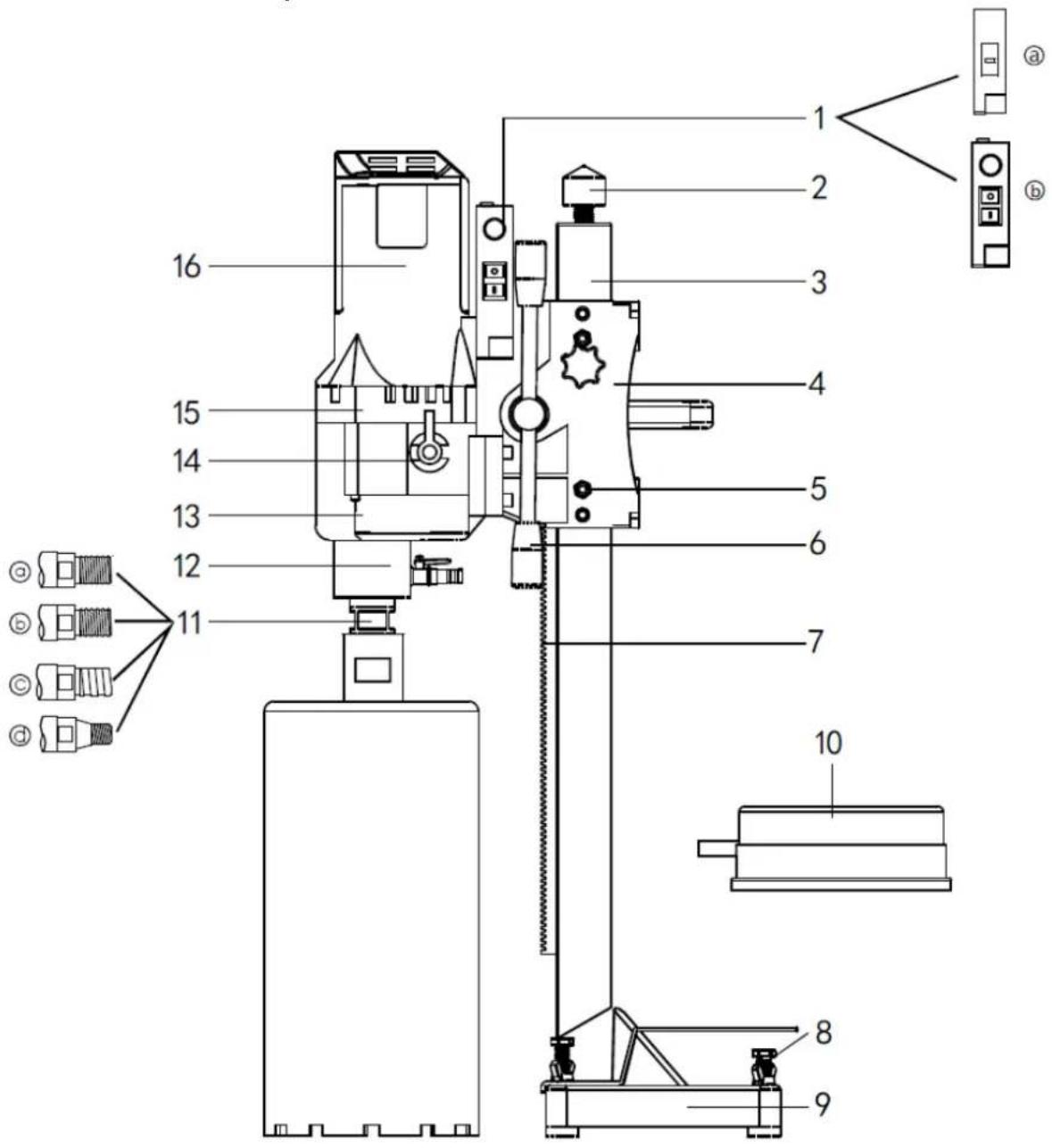
1 - Switch box
a. Ordinary
b. With speed regulator
2 - Top of the frame
3 - Square frame
4 - The lifting device
5 - The adjusting screw
6 - Lifting shaft
7 - Toothed rack
8 - Base screw
9 - Base
10 - Water collecting hood (optional)
11 - Spindle
12 - Water ring assembly
13 - Gear box
14 - Shift knob
15 - The middle cover
16 - The stator shell
3.2. Working with the device
1) Read the Manual: Before operating the machine, it is crucial to read the manual thoroughly. Only trained individuals should use this machine to ensure safety and proper handling.
2) Check the Voltage: Ensure that the power voltage does not exceed 5% of the machine's rated voltage. Higher voltages can lead to motor damage, including burning and electrical leakage.
3) Wear Appropriate Safety Gear: Always wear a helmet, insulating gloves, and a labor suit. Avoid loose clothing and jewelry, and keep hair secured to prevent entanglement.
4) Use Correct Drill Bits: This machine is designed for wet drill bits. Using other types of bits or overloading the motor is not recommended and can damage the machine.
5) Prevent Water from Entering the Motor: Ensure water does not enter the motor and do not obstruct the ventilation to prevent overheating and potential motor damage.
6) Inspect the Work Area: Before starting, check the work area for potential hazards, such as high voltage power lines, gas and water pipes, and telecommunication facilities.
7) Be Mindful of the Surroundings: Consider the safety of the area below when drilling through floors. When drilling into beams or columns, assess the building's structure for stability.
8) Avoid Explosive Environments: Do not operate the electric tool in areas with flammable liquids, gases, or dust. Sparks generated by electric tools can ignite these substances.
9) Start with No Load: Always start the machine without any load. Starting under load is dangerous and can harm both the machine and the operator. Ensure the machine is securely fixed to prevent it from falling when working at heights.
10) Use a Quality Power Cable: Employ a high-quality three-core cable and ensure it is properly grounded. Using a ground fault circuit interrupter (GFCI) is essential for additional safety.
Following these safety guidelines will help ensure the safe operation of the machine, protecting both the operator and the equipment from harm. Always prioritize safety to prevent accidents and ensure a productive working environment.
3.3. Operation Guide
1) Installing the expansion bolt:
- Drill a hole: Use an impact drill to create a hole at the specified location.
- Insert the bolt: Place the expansion bolt into the hole and tighten it securely.
- Mount the machine: Attach the diamond drill machine onto the bolt. Adjust the four regulation screws to stabilize the machine and prevent it from swaying.
2) Setting up the support rod:
- Locate the drilling spot: Identify where you want to drill.
- Adjust the rod: Position the support rod and modify the length of the push rod. Tighten the fastening screws to ensure full contact between the drilling rig's base and the surface, maintaining the drill bit and machine in a vertical and steady position.
3) Preparing for drilling:
- Attach the drill bit: Secure the correct drill bit to the machine.
- Connect utilities: Plug in the power and connect the water supply.
- Adjust and check: Turn on the machine with no load to check the drill bit's movement and listen for any unusual sounds. If all checks out, open the water valve to start drilling once water flows from the drill bit.
4) Beginning to drill:
- Start slow: Begin drilling at a slow pace to allow the drill bit to penetrate the surface.
- Adjust speed: Once the bit has made an initial hole, you can increase to normal drilling speed. Decrease speed again if you encounter steel within the drilling surface.
5) Safety and maintenance:
- Mechanical and electronic protections: If the drill bit stops moving while the motor runs, it might need sharpening, or the feed speed is too high. Withdraw and reinsert the drill bit. If the motor stops unexpectedly, restart the machine and reduce the feed speed.
- Friction plate wear: Over time, the friction plate may wear down, leading to potential slippage. Remove the clutch gear from the gearbox, replace the worn friction plates with new ones of uniform size, and tighten all screws securely. Reassemble the gear into the gearbox. (Note: This maintenance step should be performed by a trained professional.)
By following these steps, you ensure not only the efficient operation of your diamond drill machine but also uphold safety standards and prolong the life of your equipment.
3.4. Gear shifting instructions
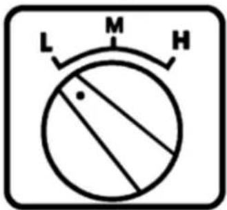
3-speed type

2-speed type
Diamond hole saws can be equipped with two or three speeds. Choosing the right gear increases drilling efficiency:
3-speed model:
• High gear (H): for drilling small holes in soft materials.
• Medium gear (M): for drilling medium-sized holes in harder materials.
• Low gear (L): for drilling large holes in very hard materials.
2-speed model:
• Only high and low gears are available.
How to change gears:
1) Make sure the machine is turned off before changing gear. The machine should be completely stopped.
2) Set the gear knob to the desired gear:
• For 3-speed model: select H, M or L.
• For 2-speed model: select H or L.
3) If, after changing gear and restarting the machine, the shaft does not rotate or abnormal noises are heard, the gear has not been engaged correctly.
a. In this case, turn off the machine immediately.
b. Turn the shift knob back and forth while turning the main shaft to engage the gear correctly.
c. Restart the machine to check that the gear is engaged correctly.
Comments:
- Do not change gears while the machine is running at full speed or under load.
• Remember to always turn off the machine before attempting to change gears.
3.5. Angle adjustment
The frame can be adjusted from 0 to 45 degrees. The process of adjusting the angle is relatively simple and requires several steps:
1) Releasing the screws: First, loosen the two screws securing the square bar to the base of the mount. This will allow you to move and adjust the angle.
2) Adjusting the Motor Spindle Position: Next, adjust the motor spindle to achieve the desired angle. This can be done by moving the square rod to the appropriate position.
3) Lock in place: Once the desired angle is achieved, tighten the locking screw nut to secure the setting. Make sure the rod remains stable and motionless in the new position.
Important Note: When tightening the screws, be careful not to overtighten them. Over-tightening may deform the square bar, making future adjustments difficult or even damage the mechanism.
3.6. Troubleshooting
| Error Cause Solution | ||
| The Motor does not work | Power off, or plug loosed Power | up, plug in |
| Carbon brush get stuck, and detach from diverter | Re-install carbon brush | |
| Reset PRCD failed Push reset button or re-start the motor | ||
| PRCD get damaged Chang PRCD | ||
| Drill Slowly | Drill bit worn out Change drill bit | |
| Feeding speed is too low Accelerate feeding speed | ||
| Drill bit was pasted by chips Clean the drill bit, enhance water pressure | ||
| Rotate speed is too high Change to low speed | ||
| Cutting on steel and slip | Reduce feeding speed, after cutting through the steel, increase it | |
| Too much chips in the hole | Clean the bottom of hole and enhance water pressure | |
| Less water supply or water leakage | Check the ball valve and the water flow | |
| Drill bit becoming glazed Re-sharp the drill bit with grinder | ||
| Drill bit Jam | The tube and drill bit or the drill bit and hole wall was jammed by chips The stand is not secured, move location | Switch off the machine, turn the drill bit right and left with wrench or pull the drill bit out and break up the core sample |
| Rotate speed is too high Re-fix the stand | ||
| Cutting on steel and slip Narrow the gap | ||
| Drill bit under cutting | Spindle is not straight Repair or replace the spindle | |
| Drill bit is not straight Replace the drill bit | ||
| Chips can't be flushed out of the hole | Enhance water pressure, pull out the drill bit, clean the hole | |
| Water jacket is leaking | The seal of skeleton is worn out | Change the seal |
3.7. Maintenance Guide
Safety precaution: Always ensure the device is unplugged from the power source before starting any maintenance or repair work. This is crucial to prevent any accidental start-up and to ensure your safety.
Cleaning the machine:
- Use a dry or slightly damp cloth to clean the machine. Avoid using water jets as they can introduce moisture into sensitive areas like the motor and switch box.
- Keep the ventilation slots clear to prevent the motor from overheating.
- Regularly clean and lubricate the core bit thread to ensure smooth operation.
- Inspect all screws periodically and tighten them as necessary to maintain the integrity of the machine.
Professional repairs: Only qualified personnel should perform repairs on your tool, and it's important to use original spare parts. This ensures the safety and longevity of your machine and prevents potential harm.
Carbon brush maintenance: After approximately 300 hours of use, check the carbon brushes for wear. If they are worn out, they need to be replaced by an electrical specialist. This is part of maintaining the motor's efficiency and reliability.
3.8. Assembly drawing
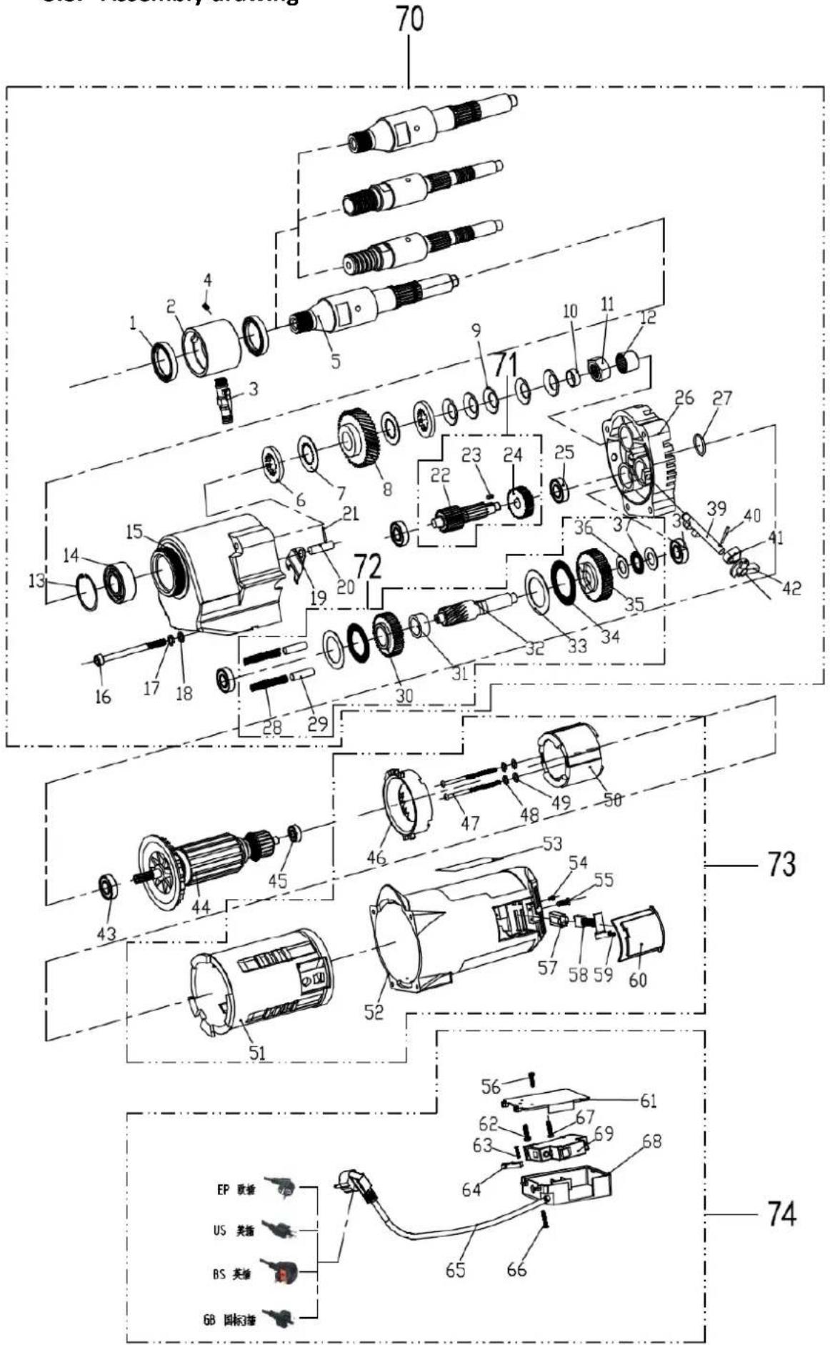
| No. | Parts Name | Qty. | No. | Parts Name | Qty. |
| 1 | Water seal 40 * 58 * 8 | 2 | 36 | Pad M35 | 2 |
| 2 | Water circle 250 | 1 | 37 | Flat Rolling Needle φ 35 | 2 |
| 3 | Faucet 200-PT | 1 | 38 | Bearing 6201 | 2 |
| 4 | Top wire M4 * 6(one word) | 1 | 39 | F gear lever 250 | 1 |
| 5 | Main axis 230 tune | 1 | 40 | Volume 5 * 12 | 1 |
| 6 | Flesh flat pad 200A | 2 | 41 | Pad 250. | 1 |
| 7 | Separation film 200A | 2 | 42 | Dialing knob 250 | 1 |
| 8 | Spindle gear 230C-6 | 1 | 43 | Bearing 6201 | 1 |
| 9 | Curved bullet pad 200A | 5 | 44 | Rotor OB-255C | 1 |
| 10 | Ring 250 | 1 | 45 | Bearing 6200 | 1 |
| 11 | Nut 200A | 1 | 46 | Bend 200 | 1 |
| 12 | Roller bearings BAM1212 | 1 | 47 | Hegonal screw M5 * 80 | 2 |
| 13 | Inner card 52 | 1 | 48 | Pad M5 | 2 |
| 14 | Bearing 3205 | 1 | 49 | Pad M5 | 2 |
| 15 | Gear box 250. | 1 | 50 | Stator OB-255C | 1 |
| 16 | Hegonal screw M6 * 110 | 4 | 51 | Gum shell 200 | 1 |
| 17 | Pad M6 | 4 | 52 | Stator shell 250 | 1 |
| 18 | Pad M6 | 4 | 53 | Parameter B(80 * 53) | 1 |
| 19 | Piece 250 | 1 | 54 | Hegonal screw M4 * 10 | 2 |
| 20 | Cylinder 9.5 * 35 | 1 | 55 | Round Cross Screw M4 * 12 | 2 |
| 21 | Volume 4 * 15 | 1 | 56 | Cross level screw M4 * 10 | 1 |
| 22 | Class I tooth shaft 230C-2 | 1 | 57 | Brush the nest 200 | 2 |
| 23 | Marketing 4 * 10 | 1 | 58 | Carbon Brush 818 | 2 |
| 24 | Class I gear 250-1(10) | 1 | 59 | Round Cross Screw M4 * 8 | 2 |
| 25 | Bearing 6201 | 2 | 60 | Brush frame 200 | 2 |
| 26 | Middle cover, 250. | 1 | 61 | Switch Box Cover 200-PT | 1 |
| 27 | O-ring φ 31.5 * 1.8 | 1 | 62 | Cross level screw M4 * 10 | 1 |
| 28 | Pulling spring φ 8 * 55 | 2 | 63 | Cross tapping screw M4 * 16 | 2 |
| 29 | Iron ring φ 10 * 35 | 2 | 64 | Threading board 200 | 1 |
| 30 | Type II high-speed gear 230C-5 | 1 | 65 | Power cord 3 * 1.0 * 3.5 M | 1 |
| 31 | Ring 250 | 1 | 66 | Cross level screw M4 * 20 | 2 |
| 32 | Class II tooth shaft 230C-4 | 1 | 67 | Cross level screw M4 * 10 | 1 |
| 33 | Rolling pin pad M40 | 2 | 68 | Switch Box 200-PT | 1 |
| 34 | Flat Rolling Needle φ 40 | 2 | 69 | Switch D18 | 1 |
| 35 | Type II low-speed gear 230C-3 | 1 |

1 - Spínací skříňka
1 - Interruttore
1 - Caja de interruptores
1 - Kapcsolódoboz
1 - Koblingsboks
| Nr. | Dele Navn | Antal. | Nr. | Dele Navn | Antal. |
| 1 | Vandtætning 40 * 58 * 8 | 2 | 36 | Pude M35 | 2 |
| 2 | Vandcirkel 250 | 1 | 37 | Flad rullende nål φ 35 | 2 |
| 3 | Vandhane 200-PT | 1 | 38 | Leje 6201 | 2 |
| 4 | Top wire M4 * 6(et ord) | 1 | 39 | F gearstang 250 | 1 |
| 5 | Hovedakse 230 tune | 1 | 40 | Bind 5 * 12 | 1 |
| 6 | Flad pude af kød 200A | 2 | 41 | Pad 250. | 1 |
| 7 | Separationsfilm 200A | 2 | 42 | Opkaldsknap 250 | 1 |
| 8 | Spindelgear 230C-6 | 1 | 43 | Leje 6201 | 1 |
| 9 | Buet kuglepude 200A | 5 | 44 | Rotor OB-255C | 1 |
| 10 | Ring 250 | 1 | 45 | Leje 6200 | 1 |
| 11 | Møtrik 200A | 1 | 46 | Bøj 200 | 1 |
| 12 | Rullelejer BAM1212 | 1 | 47 | Hegonal skrue M5 * 80 | 2 |
| 13 | Indre kort 52 | 1 | 48 | Pude M5 | 2 |
| 14 | Leje 3205 | 1 | 49 | Pude M5 | 2 |
| 15 | Gearkasse 250. | 1 | 50 | Stator OB-255C | 1 |
| 16 | Hegonal skrue M6 * 110 | 4 | 51 | Gummiskal 200 | 1 |
| 17 | Pude M6 | 4 | 52 | Statorskal 250 | 1 |
| 18 | Pude M6 | 4 | 53 | Parameter B(80 * 53) | 1 |
| 19 | Stykke 250 | 1 | 54 | Hegonal skrue M4 * 10 | 2 |
| 20 | Cylinder 9,5 * 35 | 1 | 55 | Rund krydsskrue M4 * 12 | 2 |
| 21 | Bind 4 * 15 | 1 | 56 | Krydsnivelleringsskrue M4 * 10 | 1 |
| 22 | Klasse I tandaksel 230C-2 | 1 | 57 | Pensl reden 200 | 2 |
| 23 | Markedsføring 4 * 10 | 1 | 58 | Kulbørste 818 | 2 |
| 24 | Klasse I-udstyr 250-1(10) | 1 | 59 | Rund krydsskrue M4 * 8 | 2 |
| 25 | Leje 6201 | 2 | 60 | Børsteramme 200 | 2 |
| 26 | Midterste omslag, 250. | 1 | 61 | Dæksel til koblingsboks 200-PT | 1 |
| 27 | O-ring φ 31,5 * 1,8 | 1 | 62 | Krydsnivelleringsskrue M4 * 10 | 1 |
| 28 | Trækfjeder φ 8 * 55 | 2 | 63 | Tværgående skrue M4 * 16 | 2 |
| 29 | Jernring φ 10 * 35 | 2 | 64 | Gevindbræt 200 | 1 |
| 30 | Type II højhastighedsgear 230C-5 | 1 | 65 | Strømledning 3 * 1,0 * 3,5 M | 1 |
| 31 | Ring 250 | 1 | 66 | Krydsnivelleringsskrue M4 * 20 | 2 |
| 32 | Klasse II tandaksel 230C-4 | 1 | 67 | Krydsnivelleringsskrue M4 * 10 | 1 |
| 33 | Rullepindspude M40 | 2 | 68 | Koblingsboks 200-PT | 1 |
| 34 | Flad rullende nål φ 40 | 2 | 69 | Kontakt D18 | 1 |
| 35 | Type II lavhastighedsgear 230C-3 | 1 |

1 - Kytkinlaatikko
1 - Schakelkast
| Nee. | Deel naam | Aanta I | Nee. | Deel naam | Aanta I |
| 1 | Waterslot 40*58*8 | 2 | 36 | Pad M35 | 2 |
| 2 | Watercirkel 250 | 1 | 37 | Platte rollende naald φ 35 | 2 |
| 3 | Kraan 200-PT | 1 | 38 | Lager 6201 | 2 |
| 4 | Topdraad M4 * 6 (één woord) | 1 | 39 | F-versnellingspook 250 | 1 |
| 5 | Hoofdas 230 tune | 1 | 40 | Deel 5*12 | 1 |
| 6 | Platte vleespad 200A | 2 | 41 | Pad 250. | 1 |
| 7 | Scheidingsfilm 200A | 2 | 42 | Kiesknop 250 | 1 |
| 8 | Spindeltandwiel 230C-6 | 1 | 43 | Lager 6201 | 1 |
| 9 | Gebogen kogelkussen 200A | 5 | 44 | RotorOB-255C | 1 |
| 10 | Bel 250 | 1 | 45 | Lager 6200 | 1 |
| 11 | Moer 200A | 1 | 46 | Buig 200 | 1 |
| 12 | Rollagers BAM1212 | 1 | 47 | Zeshoekige schroef M5 * 80 | 2 |
| 13 | Binnenkaart 52 | 1 | 48 | Pad M5 | 2 |
| 14 | Lager 3205 | 1 | 49 | Pad M5 | 2 |
| 15 | Versnellingsbak 250. | 1 | 50 | StatorOB-255C | 1 |
| 16 | Zeshoekige schroef M6 * 110 | 4 | 51 | Gomschaal 200 | 1 |
| 17 | Pad M6 | 4 | 52 | Statormantel 250 | 1 |
| 18 | Pad M6 | 4 | 53 | Parameter B(80 * 53) | 1 |
| 19 | Stuk 250 | 1 | 54 | Zeshoekige schroef M4 * 10 | 2 |
| 20 | Cilinder 9,5 * 35 1 55 | Ronde kruisschroef M4 * 12 | 2 | ||
| 21 | Deel 4*15 1 56 | Kruisniveauschroef M4 * 10 | 1 | ||
| 22 | Klasse I tandas 230C-2 | 1 | 57 | Borstel het nest 200 | 2 |
| 23 | Marketing 4 * 10 | 1 | 58 | Koolborstel 818 | 2 |
| 24 | Klasse I versnelling 250-1(10) | 1 | 59 | Ronde kruisschroef M4 * 8 | 2 |
| 25 | Lager 6201 | 2 | 60 | Borstelframe 200 | 2 |
| 26 | Middendeksel, 250. | 1 | 61 | Schakelkastdeksel 200-PT | 1 |
| 27 | O-ring φ 31,5 * 1,8 | 1 | 62 | Kruisniveauschroef M4 * 10 | 1 |
| 28 | Trekveer φ 8 * 55 | 2 | 63 | Kruistapschroef M4 * 16 | 2 |
| 29 | IJzeren ring φ 10 * 35 | 2 | 64 | Snijplank 200 | 1 |
| 30 | Type II hogesnelheidsoverbrenging 230C-5 | 1 | 65 | Netsnoer 3 * 1,0 * 3,5 M | 1 |
| 31 | Bel 250 1 66 | Kruisniveauschroef M4 * 20 | 2 | ||
| 32 | Klasse II tandas 230C-4 | 1 | 67 | Kruisniveauschroef M4 * 10 | 1 |
| 33 | Deegrolkussen M40 | 2 | 68 | Schakelkast 200-PT | 1 |
| 34 | Platte rollende naald φ 40 | 2 | 69 | Schakelaar D18 | 1 |
| 35 | Type II lage snelheidsversnelling 230C-3 | 1 |

OBS! Varm overflate, fare for forbrenning!

1 - Bryterboks
| Nr. | Navn på deler | Antall. | Nr. | Navn på deler | Antall. |
| 1 | Vannforsegling 40 * 58 * 8 | 2 | 36 | Pad M35 | 2 |
| 2 | Vannsirkel 250 | 1 | 37 | Flat rullenål φ 35 | 2 |
| 3 | Kran 200-PT | 1 | 38 | Lager 6201 | 2 |
| 4 | Toppledning M4 * 6 (ett ord) | 1 | 39 | F girspak 250 | 1 |
| 5 | Hovedakse 230 tune | 1 | 40 | Bind 5 * 12 | 1 |
| 6 | Flesh flat pad 200A | 2 | 41 | Pad 250. | 1 |
| 7 | Separasjonsfilm 200A | 2 | 42 | Ringeknapp 250 | 1 |
| 8 | Spindelgir 230C-6 | 1 | 43 | Lager 6201 | 1 |
| 9 | Buet kulepute 200A | 5 | 44 | Rotor OB-255C | 1 |
| 10 | Ring 250 | 1 | 45 | Lager 6200 | 1 |
| 11 | Mutter 200A | 1 | 46 | Bend 200 | 1 |
| 12 | Rullelager BAM1212 | 1 | 47 | Hegonal skrue M5 * 80 | 2 |
| 13 | Innerkort 52 | 1 | 48 | Pad M5 | 2 |
| 14 | Lager 3205 | 1 | 49 | Pad M5 | 2 |
| 15 | Girkasse 250. | 1 | 50 | Stator OB-255C | 1 |
| 16 | Hegonal skrue M6 * 110 | 4 | 51 | Tannkjøttskall 200 | 1 |
| 17 | Pad M6 | 4 | 52 | Stator skall 250 | 1 |
| 18 | Pad M6 | 4 | 53 | Parameter B(80 * 53) | 1 |
| 19 | Stykke 250 | 1 | 54 | Hegonal skrue M4 * 10 | 2 |
| 20 | Sylinder 9,5 * 35 | 1 | 55 | Rund kryssskrue M4 * 12 | 2 |
| 21 | Bind 4 * 15 | 1 | 56 | Kryssnivåskrue M4 * 10 | 1 |
| 22 | Klasse I tannskaft 230C-2 | 1 | 57 | Børst reiret 200 | 2 |
| 23 | Markedsføring 4 * 10 | 1 | 58 | Karbonbørste 818 | 2 |
| 24 | Klasse I gir 250-1(10) | 1 | 59 | Rund kryssskrue M4 * 8 | 2 |
| 25 | Lager 6201 | 2 | 60 | Børsteramme 200 | 2 |
| 26 | Mellomomslag, 250. | 1 | 61 | Bryterboksdeksel 200-PT | 1 |
| 27 | O-ring φ 31,5 * 1,8 | 1 | 62 | Kryssnivåskrue M4 * 10 | 1 |
| 28 | Trekkfjær φ 8 * 55 | 2 | 63 | Kryssskrue M4 * 16 | 2 |
| 29 | Jernring φ 10 * 35 | 2 | 64 | Trådbrett 200 | 1 |
| 30 | Type II høyhastighetsgir 230C-5 | 1 | 65 | Strømledning 3 * 1,0 * 3,5 M | 1 |
| 31 | Ring 250 | 1 | 66 | Kryssnivåskrue M4 * 20 | 2 |
| 32 | Klasse II tannskaft 230C-4 | 1 | 67 | Kryssnivåskrue M4 * 10 | 1 |
| 33 | Kjevlepute M40 | 2 | 68 | Bryterboks 200-PT | 1 |
| 34 | Flat rullenål φ 40 | 2 | 69 | Bryter D18 | 1 |
| 35 | Type II lavhastighetsgir 230C-3 | 1 |

1 - Byt läda
1 - Spínacia skrinka
For the disposal of the device please consider and act according to the national and local rules and regulations.
CONTACT
expondo Polska sp. z o.o. sp. k.


- General description
- DO NOT USE THE DEVICE UNLESS YOU HAVE THOROUGHLY READ AND UNDERSTOOD THIS USER MANUAL.
- Legend
- Usage safety
- Electrical safety
- EN
- Safety in the workplace
- Personal safety
- Safe device use
- Use guidelines
- Device description
- Working with the device
- Operation Guide
- 2) Setting up the support rod:
- 3) Preparing for drilling:
- 4) Beginning to drill:
- 5) Safety and maintenance:
- Gear shifting instructions
- 3-speed model:
- 2-speed model:
- How to change gears:
- Comments:
- Angle adjustment
- Maintenance Guide
- Cleaning the machine:
- - Caja de interruptores
- CONTACT
Brand : MSW
Model : DDM-A4250S
Category : Drill