
SinePower DSP-EM - Smart Home DOMETIC - Free user manual and instructions
Find the device manual for free SinePower DSP-EM DOMETIC in PDF.

User questions about SinePower DSP-EM DOMETIC
0 question about this device. Answer the ones you know or ask your own.
Ask a new question about this device
Download the instructions for your Smart Home in PDF format for free! Find your manual SinePower DSP-EM - DOMETIC and take your electronic device back in hand. On this page are published all the documents necessary for the use of your device. SinePower DSP-EM by DOMETIC.
USER MANUAL SinePower DSP-EM DOMETIC
Please read this instruction manual carefully before installation and first use, and store it in a safe place. If you pass on the product to another person, hand over this instruction manual along with it.
Table of contents
1 Explanation of symbols. 7
2 Safety instructions. 8
3 Scope of delivery 9
4 Accessories. 9
5 Intended use 9
6 Technical description 10
7Assembling and connecting DSP-EM 10
8 Putting DSP-EM into operation 11
9 Using DSP-EM. 12
10 Troubleshooting 16
11 Warranty 17
12 Disposal. 17
13 Technical data. 17
1 Explanation of symbols

WARNING!
Safety instruction: Failure to observe this instruction can cause fatal or serious injury.

CAUTION!
Safety instruction: Failure to observe this instruction can lead to injury.

NOTICE!
Failure to observe this instruction can cause material damage and impair the function of the product.

NOTE
Supplementary information for operating the product.
2 Safety instructions
The manufacturer accepts no liability for damage in the following cases:
- Damage to the product resulting from mechanical influences and incorrect connection voltage
- Alterations to the product without express permission from the manufacturer
- Use for purposes other than those described in the operating manual
Note the following basic safety information when using electrical devices to protect against:
Electric shock
• Fire hazards
·Injuries

WARNING!
- Electrical devices are not children's toys!
Always keep and use the device out of the reach of children.
- This device can be used by children aged 8 years or over, as well as by persons with diminished physical, sensory or mental capacities or a lack of experience and knowledge, providing they are supervised, or have been taught how to use the device safely and are aware of the resulting risks.
- Only use the device as intended.
- Lay the cables so that they cannot be damaged by the doors or the bonnet. Crushed cables can lead to serious injury.

CAUTION!
- Lay the cables so that they cannot be tripped over or damaged.
-
Do not operate the device:
-
In salty, wet or damp environments
-
In the vicinity of corrosive fumes
-In areas where there is a danger of explosions -
Always disconnect the power supply when working on the device.
- Please observe that parts of the device may still conduct voltage even if the fuse has blown.
- Do not disconnect any cables when the device is still in use.

NOTICE!
- Use ductwork or cable ducts if it is necessary to lay cables through metal panels or other panels with sharp edges.
- Do not lay the cable so that it is loose or heavily kinked.
- Fasten the cables securely.
- Do not pull on the cables.
3 S C O P E O F D E I
| Item in fig. 1, page 3 | Quantity Description | |||||
| 1 | 1 | D | i | s | p | l |
| 2 | 1 | C | o | n | n | e |
| 3 | 4 Fastening screws | |||||
| 4 | 1 Drill template | |||||
4 Accessories
Available as accessories (not included in the scope of delivery):
| Description | Ref. no. |
| Battery sensor, MCA-HS1 Hella sensor | 9102500038 |
| IBS multiplexer | 9600002566 |
5 I n t e n d e d u s

WARNING!
Also observe the instructions in the operating manuals of the connected devices.
DSP-EM is used for controlling, setting and the status display of devices that are connected to the CI bus.
A connected MCA battery charger and the following inverters can be operated remotely with this:
- DSP1312T, DSP1812T, DSP2312T, DSP3512T, DSP1324T, DSP1824T, DSP2324T, DSP3524T
The DSP-EM is the energy monitor for a connected battery sensor of the MCA-HS1 Hella sensor type.
With an IBS multiplexer, up to four battery sensors can be connected. If no inverter is connected, an IBS multiplexer is required for the energy supply.
6 Technical description
6.1 Function
A connected inverter can be switched on and off and be configured.
A connected MCA battery charger can be switched to sleep mode.
DSP-EM can communicate with a battery sensor of the MCA-HS1 Hella sensor type. With an IBS multiplexer, up to four battery sensors can be connected.
6.2 Display and control elements
| Item in fig. 2, page 3 | Description Explanation | |
| 1 | Selector button | Turn: Navigate through menus or change values Press: Select menu items or values |
| 2 For connected inverter: | Deactivates the inverter function and thus the power supply of the battery to the 230 V consumer units. The battery is not discharged via the inverter. | |
| 3 For connected MCA charger: | Switches the night mode of the connected device on or off. The charging current of the connected device is limited and the fan switches off. | |
| 4 Display Displays values and current statuses of the connected devices. | ||
7 Assembling and connecting DSP-EM
When selecting the installation location, note the following:
- The device must be installed in a location that is protected from moisture.
- Do not install the device in a dusty environment.
- The device must be installed on a level and sufficiently sturdy surface.
- Note the length of the connection cable.
- Install the device in a well-protected location to ensure no objects can touch the connection cable or cause it to tear.
Prepare the cut-out in the wall with the template included in the scope of delivery.
Mount the display as shown (fig. 3, page 4).
Connect the display as follows(fig. 4, page 5).
8 Putting DSP-EM into operation
DSP-EM checks whether the connected devices are setup during start up.
Connect the Display.
If a setup has not been done, the service menu opens:
The number "1" appears.
Use the table to determine the necessary value for your connected devices:
Valueconnected devices
| 1 | o | n | l | y | b | a | t | t | e | n |
| 2 only MCA battery charger | ||||||||||
| 3 battery sensor and MCA battery charger | ||||||||||
| 4 | o | n | l | y | D | S | P | - | T | i |
| 5 battery charger and DSP-T inverter | ||||||||||
| 6 MCA battery charger and DSP-T inverter | ||||||||||
| 7 battery charger, MCA battery charger and DSP-T inverter | ||||||||||
Turn the selector button until the determined value is displayed.
Press the selector button to save the value.
Without connected battery sensor
Press the selector button until the display is no longer illuminated.
DSP-EM can now be put into operation.
With connected battery sensor
The display indicates "service code 12".
Continue with the setup as described in the following chapter (chapter "Starting up the battery sensor" on page 12).
8.1 Starting up the battery sensor
Use the table to determine the necessary value for your battery type:
| Value Type of battery | |||||||||
| 0 Lead acid battery | |||||||||
| 1 | G | e | I | - | b | a | t | t | e |
| 2 | A | G | M | - | b | a | t | t | e |
| 3 eStore-battery | |||||||||
Press the selector button.
Turn the selector button until the determined value is displayed.
Press the selector button to save the value.
The display indicates "service code 13".
Determine the capacity of your batteries (0 - 500 Ah).
Press the selector button.
Turn the selector button until the determined capacity is displayed.
Press the selector button to save the value.
DSP-EM switches off and can now be put into operation.

NOTE
Only for specialists
The advanced service settings can be found in the service guide at dometic.com/manuals.
The advanced service settings must be performed by specially trained personnel. An incorrect setting of the values can impair the functionality of the connected devices.
9 U s i n g D S P - E
9.1 Display
| Item in fig. 5, page 5 | Explanation | |||||||||
| 1 | M | e | n | u | s | |||||
| 2 | S | t | a | t | u | s | d | i | s | p |
| 3 | Display of values | |||||||||
| 4 | Display of values as a bar chart | |||||||||
9.2 Menus
| Symbol Menu Displayed values | ||
| - + | Battery menu | Without battery sensor • Input voltage on the inverter With battery sensor The battery is being charged: → - + |
| · Time remaining until the battery is fully charged · Battery voltage · Charging current Bar chart: Charging status of the battery in percent | ||
| The battery is discharging: → - + | ||
| · Remaining time · Battery voltage · Used battery power Bar chart: Charging status of the battery in percent | ||
| AC load menu • Remaining time · Battery voltage · Used battery power Bar chart: Charging status of the battery in percent | ||
| Service menu Only for specialists The advanced service settings can be found in the service guide at dosmetic.com/manuals | ||
9.3 Status displays
| Symbol Menu | |
| Battery is charging | |
| Battery is discharging | |
| AC mains power is connected | |
| Inverter is operating Consumer units can be connected If there is a power cut, the inverter supplies the consumer units with power from the battery | |
| Energy saving mode is switched off | |
| The charger is operating in night mode | |
| Inverter is switched off 230 V consumer units are now supplied with power via the mains power supply | |
| With battery sensor Low battery charge |
9.4 Navigating within the menu
Navigate through the menus as follows:
Turn the selector button (fig. 2 1, page 3), to scroll through the menu pages.
The selector button can be turned in both directions. When the last menu item has been reached, the display goes back to the first menu item.
The symbol of the selected menu (fig. 5 1, page 5) is displayed.
The first value is displayed (chapter "Menu" on page 13).
Press the selector button to show the next value.
The following figure shows how you can navigate within the menu:
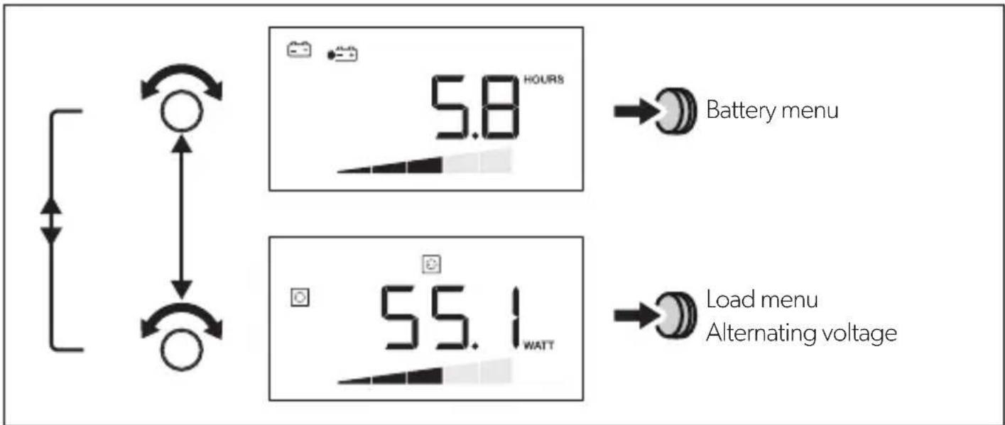
Press the selector button to show the next value in the current menu (chapter "Menu" on page 13).
Switching inverter on/off
Press to switch off the inverter.
Press again to switch on the inverter.
Switching on the display
The display switches off after a defined time.
Press the selector button or or , to illuminate the display.
10 Troubleshooting
If the system detects an error, it switches off independently. The toolbar and the display bar are hidden.
| Source | Error code | Possible cause Possible Solution |
| DSP E-01 | Battery undervoltage Charge the battery. | |
| E-02 Battery overload Reduce the input voltage. | ||
| E-03 Inverter overload Reduce the connected load. | ||
| E-04 – Overheating of the inverter | Ensure sufficient air supply at the inverter. | |
| E-05 | ||
| E-06 Initialisation error Contact customer service. | ||
| E-07 Uninterrupted power supply is not present | • Activate the inverter function (chapter “Switching inverter on/off” on page 15). • Check the connection to the mains power supply. | |
| Display E-16 CI bus does not respond | Check the BUS cabling of the battery sensor. | |
| E-17 DSP-T does not respond | • Set the main switch to REMO. • Check the BUS cabling of the DSP-T inverter. | |
| E-19 MCA does not respond | Check the BUS cabling to the MCA charger. | |
| E-20 Battery charging status too low | Charge the battery. | |
11 Warranty
The statutory warranty period applies. If the product is defective, please contact the manufacturer's branch in your country (see the back of the instruction manual for the addresses) or your retailer.
For repair and guarantee processing, please send the following items:
- Defect components
A copy of the receipt with purchasing date - A reason for the claim or description of the fault
12 Disposal
Place the packaging material in the appropriate recycling waste bins wherever possible.
If you wish to finally dispose of the product, ask your local recycling centre or specialist dealer for details about how to do this in accordance with the applicable disposal regulations.
13 Technical data
| DSP-EM | |
| Ref. no.: 9600002565 | |
| Input voltage: 9 - 35 V== | |
| Power consumption in display mode: in standby mode: | 170 mA 40 mA |
| Display dimensions: | fig. 6, page 6 |
| Certification: | CE E13 |
6 Description technique
6.1 Fonctionnement
9.3 Statusindications
I3rOToBHTen He HecET HnKaKoI OTBeTCTBeHHOCTHa yUepe6 B CneDyUOuNX CnyuaX:
-Поврждени поюкту n3-3a МexанческIx BOЗдевский И Неверно наразжени ппаня
- I3MeHeHnB PpOdyKTe, BbIOnHeHHbIe 6e3 OndHO3HaUHOro pa3peUeHnN3rTOBHTeJIa
- IcnoIb3OBAHnE B UeIaX, OTNnUHbIX OTyKa3aHHbIX B DaHHo INHCTpyKuIN
CobnIouaTe cneyuOuine o6uine yka3aHnno texnke 6e3oNaChocTn npn noB3OBaHn n eKtpopnpnbopamn, uTo6bHe donyctntb:
- NopaxeHnəJIeKTpUYeCKnM TOKOM
- n o x a p a
TpaB M

PPEyPExkEHNIE!
- 3néktpoŋp6opbI He ABJIAOTc DeTCKMn HrpyuKaAMN!
IOnToMvXpaHnte NHCNoB3yIte np6Op B HeIOCTynHom IJra DeTei MeCTe.
- 3TO yCTPOIcTBO MOXET NcONb3OBaTbC ATebMn C 8-MN NeT N CTapWe, a TaKKe IINuAMN COrpaHnueHHbIMNΦn3NueCKIMN, CEHCOPHBIMN UyMCTBeHHbIMN BO3MOXHOCTaMNI ININ pRn HeIOCTaTKe Heo6xOdIMOrO ONbTa N 3HaHn TOnbKO NOD pRncmOTpOM ININ Pocne INPOXOXeHnI INCTpykTaXa NO 6e3ONaCHOMY NcONb3OBaHnIO YCTPOIcTBa, ECIN OHN IOHIMaIOT ONaCHOCTN, KOTOpBle pRn 3TOM MOY TB03HnKHyTb.
- IcnoNb3yIte np6Op TOnbKO nHa3HaueHnIO.
- Покладыbaite npoboda TaK, уTo6bI NCKIOUHTb IX NOBpeXeHne DBepaMn INN KaNoTOM. 3axaTbe Ka6eNN MOrY TnpOBODITb K ONaChbIM dIЯ XN3Hn TpaBMam.

OCTOPOXHO!
- PpoknabBaIte npoBOna TaK, UTO6bI NCKNIOUHTb ONaCHOCTb CNOTbKaHn I NOBpeXdEHH Ka6eH.
He 3KcnnnyatnpuYte np6op B yCNOBnX BbICOKO BnaXHOCTN IN BbICOKOTo COePxAHNA B O3DyXe -B6n3n NCTOCHNKOB aRpeCCNBbIX napOB -BO B3pBIOONaCHbIX 3OHAX
-Перед Выллоннем pa6OT ha пибор otknIOUHTe пибор OT nCTOHyKa nITaHn. - YuTInTe, yTo IaXe nocne cpa6aTaBbAHHa 3aUHTHO rO yCTpoiCTBa (npedoxpAHNTe) actn npnbopa mOryt OCTaBaTbCn oHnprxHeHnEM.
He oTcoeHNHnTe Ka6eN, ecn npnbop ewe haxoDntcB pa6ote.

BHIMAHHE!
- Ecnn Heo6xOIMO npOBecTn 3NeKtpnueCKne npOBoJa Ype3 MeTaIINueCKne CTeHKn INI CTeHKn C OCTpbIMN KpaAMN, TO INCNoJIb3yIte MeTaIINOpyKaBa INI Ka6eNbHbE BBOJbl.
He npoknaIbBaIte npoBOna He3aKpeHnEHbIMn IIN CNlbHO n3OrHyTbIMN. - ObecneuBaIte HaexHoe KpeIeHne npOboIOB.
He TAHnTe 3a npoBOda.
3NaueHne PnpcoeAnHeHHbIyctpoiCTBa
TOnbKO DaTUnk aKKyMnyTota
2 Tontbko 3apraHoe yctpoiCtBO MCA
3ДатунakкуmpлеториЗapядhoe yctpoicTBO MCA
4 TOnbko nHBeptop DSP-T
5ДатчИКаKKуMЛЯТОРи ИНВeрТОРDSP-T
6 3apraHoe yctpoiCtBO MCA n HBeptop DSP-T
7ДатчИКаKKуMЛЯТОРа,ЗарядhoeустpoIcTBO MCAиИнВeртOp DSP-T
BpaaIte KhoNk Ky BbIbopa Do Tex nop, Noka He NoRbITcOnpeJeHHe 3NaueHne.
Дя coхраеня 3нayehня haxmnte KhoNky Bbl6opa.
Бe3 npncoeHHeHHoro daTUnka aKKymyIaTopa
BpaaainTe KhoNky Bb6opa Do Tex nop, Noka DnCnnne He nepeCTaHET CBeHTbcra.
Tenepb moxho BBectn DSP-EM B 3Kcnnyatauio.
C npncoeiHHeHHbIM daTchNKOM aKKymyIaTopa
Ha dincnnee noaBnayetc coo6ueHne «Service Code 12».
ПродлжITEHaJaKy,КakОписанВспeДуюшeгЯBaBe(П.«ВБODДaТчИKa aKKyMnyTopaBЗкпFlyatauH»Ha cTp.133).
8.1 BbOДдатчиKa aKKymyЯTopaВЭКплyaTaцИо
Ha ochoban Ta6nIbI onpeDenIte Tpe6yemoe 3naeHne IraBaWeTo Tnpa aKkymyTopa:
Ecni ciStema o6HapxNbaet HeNCpPaBHOCTb, OHa aBTOMaTnueCKN BbIKNUOaETc. NaHeIb cIMBOIOB IN DaIpaMMbl Ncye3aOT.
9 O b s I u g a D S F
9.1 Wyswietlacz
9 O b s I u h a D S F
9.1 Displej
dometic.com/sales-offices


