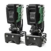
ESY I/O - Water pump DAB - Free user manual and instructions
Find the device manual for free ESY I/O DAB in PDF.


| Product Type | Extension module for Esyline pumps |
| Power Supply | 100-240 VAC, 50-60 Hz, 125 mA (max) |
| Digital Inputs | 4 opto-isolated inputs (DC or AC 50-60 Hz) |
| Relay Outputs | 4 NO contacts, max 5 A @ 230 VAC (resistive), 2.5 A (inductive) |
| Pressure Sensor | 1 input for HUBA 0-25 bar sensor |
| Serial Communication | RS485 Modbus RTU (half-duplex, up to 32 devices) |
| Wireless Communication | WiFi 802.11 b/g/n 2.4 GHz, Bluetooth V4.2 BR/EDR/BLE, proprietary DAB (IEEE 802.15.4) |
| Protection Rating | IP55 |
| Operating Temperature | 0 °C to +50 °C |
| User Interface | Status LEDs and touch buttons (Wireless, WiFi) |
| Control Application | DConnect (Smart Solution) - configuration and update |
| Firmware Update | Via DConnect app (duration ≤ 5 minutes) |
| Mounting | Wall-mounted with removable front panel |
| Power Cable Cross-section | Copper min. 0.8 mm² (AWG 18), sheath diameter 5-10 mm |
| Input Terminals | Max cable cross-section 1.5 mm² |
| Output Terminals | Max cable cross-section 2.5 mm² |
| Insulation Class | Class I |
| Safety Standards | IEC 64/2 (Italy), IEC 364 (technical personnel) |
| Country of Manufacture | Italy (DAB brand) |
Frequently Asked Questions - ESY I/O DAB
User questions about ESY I/O DAB
0 question about this device. Answer the ones you know or ask your own.
Ask a new question about this device
Download the instructions for your Water pump in PDF format for free! Find your manual ESY I/O - DAB and take your electronic device back in hand. On this page are published all the documents necessary for the use of your device. ESY I/O by DAB.
USER MANUAL ESY I/O DAB
Manuel applicable aux versions de firmware 1.xx (FR)
- Riavvitare pannello

Figura 2: Etichetta Esy I/O
Figura 3: Schermata principale APP Dconnect
1.1 Content of the pack.... 14
1.2 Applications.... 14
- INSTALLATION....14
2.1 Electrical connections.... 15
2.2 Product characteristics 16
2.3 User interface 16
2.4 Local connection via APP 17
2.5 Updating the software 17
2.6 Dab Proprietary Wireless connection 17
2.7 Optoisolated digital inputs....18
2.8 Output contacts....19
2.9 Remote pressure sensor 20
2.10 RS485 Modbus RTU connection.... 21
2.11 Fault management 23
- PROBLEM SOLVING 24
KEY
The following symbols have been used in the discussion

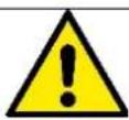
SITUATION OF GENERAL DANGER.
Failure to respect the instructions that follow may cause harm to persons and property.
SITUATION OF ELECTRIC SHOCK HAZARD.
Failure to respect the instructions that follow may cause a situation of grave risk for personal safety.

Notes and general information.
WARNINGS

The products dealt with in this discussion fall within the category of professional equipment and belong to insulation class 1.

Read this documentation carefully before installation. Installation and operation must comply with the local safety regulations in force in the country in which the product is installed. Everything must be done in a workmanlike manner
Failure to respect the safety regulations not only causes risk to personal safety and damage to the equipment, but invalidates every right to assistance under guarantee.

Skilled personnel
Installation must be carried out by competent, skilled personnel in possession of the technical qualifications required by the specific legislation in force. The term skilled personnel means persons whose training, experience and instruction, as well as their knowledge of the respective standards and requirements for accident prevention and working conditions, have been approved by the person in charge of plant safety, authorizing them to perform all the necessary activities, during which they are able to recognize and avoid all dangers. (Definition for technical personnel IEC 364)
This appliance can be used by children aged from 8 years and above and persons with reduced physical, sensory or mental capabilities or lack of experience and knowledge if they have been given supervision or instruction concerning use of the appliance in a safe way and understand the hazards involved.
ENGLISH

Safety
Use is allowed only if the electric system is in possession of safety precautions in accordance with the regulations in force in the country where the product is installed (for Italy CEI 64/2).

The power supply cable must never be used to carry or shift the device.
Never pull on the cable to detach the plug from the socket.
Failure to observe the warnings may create situations of risk for persons or property and will void the product guarantee.
Particular warnings
Always switch off the mains power supply before working on the electrical or mechanical part of the system. Before opening the equipment, wait at least five minutes after disconnecting it from the power supply. Only firmly cabled mains connections are admissible.
1. GENERAL
ESY I/O is designed to provide the Esyline range of products with optoisolated inputs and outputs, access via BMS systems via MODBUS RTU Rs485, remote pressure sensor.
ESY I/O is configured and updated via the DConnect APP.
1.1 Content of the pack
- ESY I/O
- Quick Guide.
1.2 Applications
Esy I/O allows the following applications:
- connection to BMS (Build Management Systems) equipped withRS485 MODBUS RTU interface
- Connection with clean contact inputs (e.g. floats)
• Output connection, (e.g. sirens) - Connection of remote pressure sensor, to compensate for pressure losses
2. INSTALLATION
For the first installation, if wall mounting is necessary, proceed as described below:
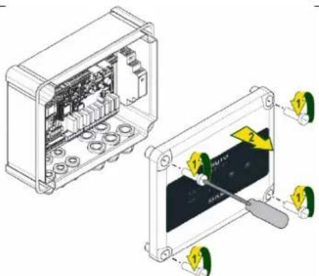
- Remove the front panel by unscrewing the 4 retaining screws with a straight tip screwdriver.
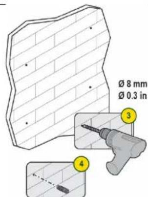
- Drill holes in the wall and insert fixtures aligned with the panel columns
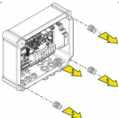
- Remove the clips for tightening the plastic screws of the panel
ENGLISH
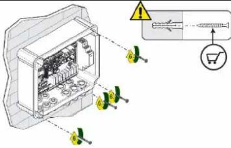 4. Screw the panel onto the wall 4. Screw the panel onto the wall | 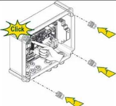 5. Replace the clips for tightening the plastic screws of the panel 5. Replace the clips for tightening the plastic screws of the panel | 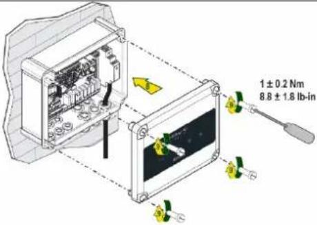 6. Screw the panel on again 6. Screw the panel on again |

Before screwing the panel back on, make sure that the cable between the two boards is correctly connected!
2.1 Electrical connections
ESY I/O requires the connection of an L-N single-phase power supply cable, the characteristics of which must be as follows:
- Single cable copper section minimum 0.8mm ^2 (AWG 18)
- Maximum sheath diameter 10mm
-
Minimum sheath diameter 5mm
-
Insert the cable in the cable gland shown in Figure 1, circled in orange (Cable gland 3)
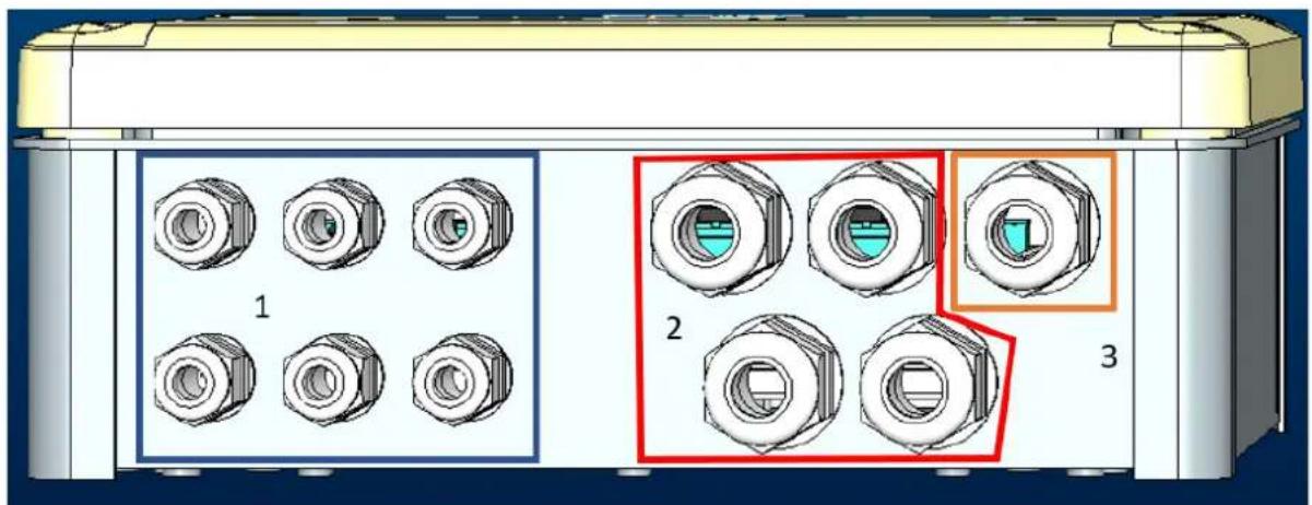
Figure 1: Front view of cable glands
- Connect the power cable before closing the front panel as shown below:
- Tighten the cable gland to maintain the IP rating of the panel
Depending on the application, the user can make other electrical connections, see Figure 1.
The cable glands in section 1 are used to wire Inputs (see Paragraph 2.7), pressure sensor (see Paragraph 2.9) and Rs485 Modbus (see Paragraph 2.10).
The cable glands in section 2 are used to wire Outputs (see Paragraph 2.8).
2.2 Product characteristics
The product characteristics are listed below:
- Supply voltage: 100-240 VAC
- Frequency: 50-60Hz
- Rated current (rms) @ 230 VAC: 125 mA
- Optoisolated digital inputs: 4
- Output: 4 NO (Normally open), max 5A @230VAC
- 1 RS485 (Modbus RTU)
- Working temperature: 0 -50 °C
- Protection rating: IP55
- Radio Modules:
DAB Proprietary Wireless (IEEE 802.15.4), FFC ID: OA3MRF24J40MA
○ Wifi (802.11 b/g/n 2.4 GHz)
- Bluetooth V4.2 BR/EDR, Bluetooth LE
2.3 User interface
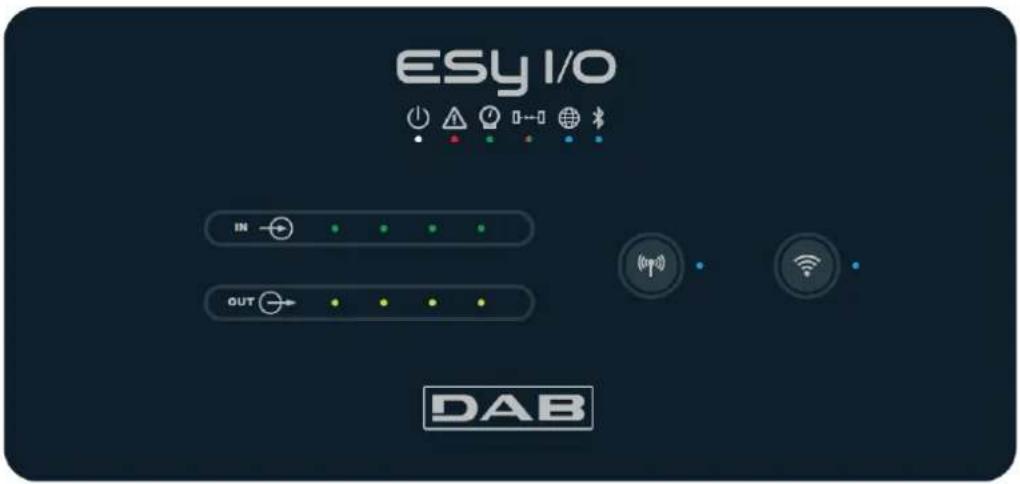
Figure 2: Esy I/O label
On the Esy I/O there are LEDs indicating the system operating status.
| Characteristics of the LEDs | |||
| Led | Colour | Description | |
 Power Power | White | On: Esy I/O poweredOff: Esy I/O not powered | |
 Fault Fault | Red | Lit blinking: Error present (see paragraph 2.10)Off: No error | |
 Pressure Pressure | Green | On: Pressure sensor connectedOff: Pressure sensor not connected | |
 Modbus Modbus | Green/Red | Steady green: Gateway modbus activeRegular blinking green: Modbus gateway in alignmentGreen with temporary blinking: message transmission in progressSteady red if error (error message, timeout error)Blinking red: Modbus Gateway alignment errorOff: Gateway modbus not active | |
 Internet Internet | Blue RFU | ||
 Bluetooth Bluetooth | Blue | On: Bluetooth connection activeOff: Bluetooth connection not active | |
 Input (4 leds) Input (4 leds) | Green | On: Corresponding input energised (e.g. contact closed)Off: Corresponding input not energised (e.g. contact open) | |
 Output (4 leds) Output (4 leds) | Yellow | On: Corresponding relay closedOff: Corresponding relay open | |
 Dab Proprietary Wireless Dab Proprietary Wireless | Blue | On with a fixed light: wireless communication presentOn blinking: Network configuration present, but connection not active or not complete | |
ENGLISH
| Off: Wireless network configuration not present | ||
| Wifi | Blue | On: Wifi connection presentBlinking:AP modeOff: Wifi connection not present |
Table 1: Led Description
Esy I/O has two touch buttons in the interface (Wireless and wifi). When the touch button is pressed, the corresponding LED blinks rapidly. The implementation of the commands, described below, is confirmed by a beep.
2.4 Local connection via APP
The "Smart Solution" DConnect APP is the interface for local control of the Esy I/O device. Via the DConnect APP you can update the product and configure the main parameters of the device with the convenience of an easy-to-use and always handy APP. Via the APP it is possible to interact locally with the product through the "Direct Connection" menu accessible directly from the main page of the APP.
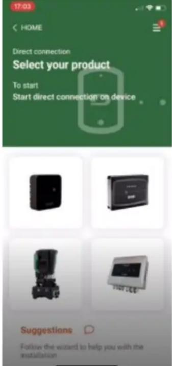
Figure 3: Dconnect APP main screen
Select the image related to the Esy I/O product, and follow the instructions during the process.
2.5 Updating the software
Updates ensure a better use of the services offered by the product. Before starting to use the product, make sure that it is updated to the latest software version available. During the software update the products involved cannot carry out their functions. For this reason a manned update is recommended.
NOTE 1: The update can take up to 5 minutes per product and when it ends the device will restart.
2.6 Dab Proprietary Wireless connection
The basic function of the Esy I/O is that it can be connected by means of a wireless interface 802.15.4, equipped with a DAB proprietary protocol, to one or more supported e.syline products.
The proprietary wireless connection is also necessary for the alignment to use Esy I/O as Modbus gateway (see Paragraph 2.10)
Proprietary wireless connection procedure
It is possible to connect the Esy I/O to a device or to several devices using the following procedure:
- Put the device to be connected into association status (see the manual of the product to be associated)

- Press the key on Esy I/O for a least 5 seconds, then wait for the blue led (seeTable 1) to light up with a fixed light.
To interrupt the procedure it is possible to press the left key on the Esy I/O.
ENGLISH
In the event of a momentary disconnection of the associated device, the blue LED will flash to indicate that the device is not connected, but is trying to restore the connection.
The wireless network configuration is maintained even in the case of a temporary power cut or if the device is switched off.
Disconnection procedure and resetting of the wireless configuration.

Hold down the key for 5 seconds. If the operation has been successful the blue LED will be off.
2.7 Optoisolated digital inputs
ESY I/O has the possibility to connect up to 4 optoisolated inputs.
The 4 digital inputs are optoisolated, they can be energised either with continuous negative and positive voltages or with alternating current at 50-60 Hz. Table 2 describes the characteristics and the limits of the digital inputs:
| Characteristics of the inputs | ||
| DC inputs [V] | AC inputs 50-60 Hz [Vrms] | |
| Minimum switch-on voltage [V] | 6.2 | 4.5 |
| Maximum switch-off voltage [V] | 2 | 1.5 |
| Maximum admissible voltage [V] | 40 | 40 |
| Current absorbed at 12V [mA] | 1.4 | 1.4 |
| Max. accepted cable section [mm2] | 1.5 | |
Table 2: input characteristics
The optoisolated terminals are connected by applying a voltage to the terminals or by connecting the common signal to GND as a jumper and connecting the In signal to a contact (e.g. float, pressure switch, etc.)
| Input wiring | |||
| Input connected to clean contact | Voltage input | ||
| Input | Clean contact between pins | Jumper | Connection |
| I1 | I1-V+ | C1/2 - CM | I1 – C1/2 |
| I2 | I2-V+ | C1/2 - CM | I2 - C1/2 |
| I3 | I3-V+ | C3/4 - CM | I3 – C3/4 |
| I4 | I4-V+ | C3/4 - CM | I4 – C3/4 |
Table 3: Input wiring
Below, Figure 4: Example of clean contact connectionFigure 4, an example of clean contact wiring on I1.
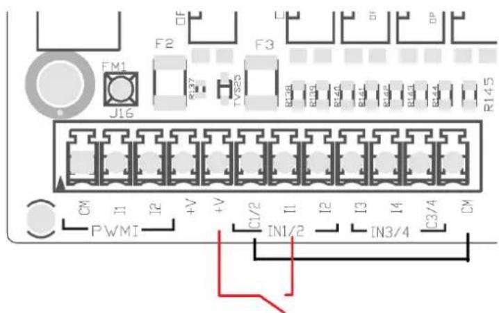
Figure 4: Example of clean contact connection
For the configuration of the inputs (e.g. Float Pressure Switch, Disable, etc.), refer to the manual of the device connected to ESY I/O. The input status is displayed both by the Input LEDs (see Table 1), and on the APP Status page (see Figure 5).
ENGLISH
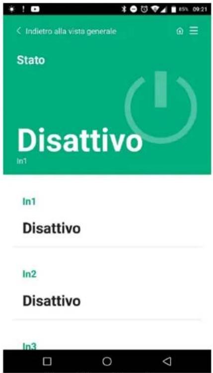
Figure 5: Input Status Page
2.8 Output contacts
The connections of the outputs listed below refer to the terminal board indicated with screen printing O1, O2 and CA.
Table 3 describes the characteristics and limits of the output contacts.
| Characteristics of the output contacts | |
| Type of contact | NO (Normally open) |
| Max. bearable voltage [V] | 230 VAC |
| Max. bearable current [A] | 5 -> resistive load2.5 -> inductive load |
| Max. accepted cable section [mm2] | 2.5 |
Table 4: Characteristics of the output contacts
The correspondences between relays and outputs are described below:
| Label | Corresponding Output |
| RL6 | O1 |
| RL7 | O2 |
| RL8 | O3 |
| RL9 | O4 |
Table 5: Relay Output correspondence
An example of a connection is shown below, on output O1 with a 230V load.
ENGLISH
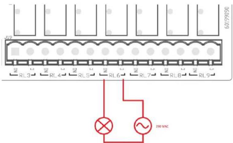
Figure 6: Example of O1 connection with 230V load
Switching on and off will depend on the settings made on the device/group of devices (see associated product manual). The output status is displayed both by the Output LEDs (see Table 1), and on the APP Status page (see Figure 7).
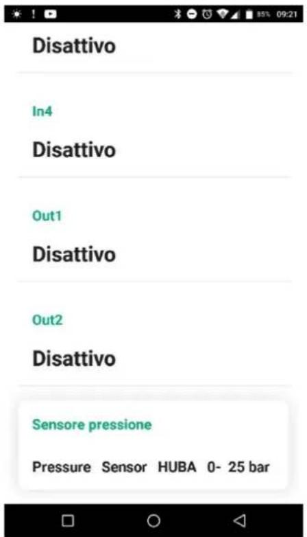
Figure 7: Output Status Display
2.9 Remote pressure sensor
The Esy I/O allows the use of 1 remote pressure sensor, directly on the 4-pole connector PR1 (see Figure 8).
ENGLISH

Figure 8: Connection of the pressure sensor
The mode of use will depend on the settings made on the device/group of devices (see associated product manual). Via the Dconnect APP, it is possible to select the sensor used.
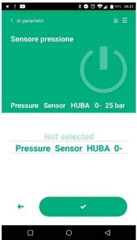
Figure 9: Pressure Sensor Setting Page
The following sensors are currently supported:
1) HUBA pressure sensor 0-25 bar
2.10 RS485 Modbus RTU connection
Esy I/O can be used as an RS485 gateway, with MODBUS RTU protocol, in order to perform data monitoring and control on devices supported by Esy I/O.
ENGLISH
Wiring
Modbus communication with 2-wire RS485 contemplates the use of 3 cables (A, B and GND). Connect the 3 cables correctly. It is recommended to use a screened 2-pole cable, with a twisted pair, adapted to 120 ohm if termination resistors are to be used.
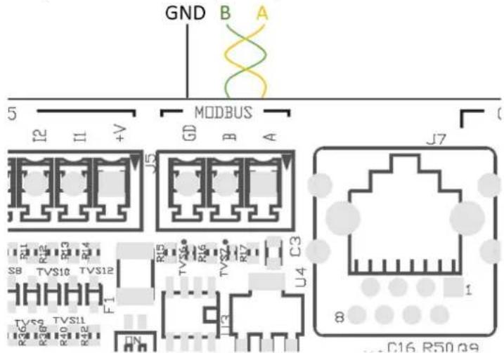
Figure 10: Rs485 Modbus Wiring
| MODBUS Terminals | Description |
| A | Terminal - |
| B | Terminal + |
| GND | Reference |
Table 6: Description of Rs485 Terminals
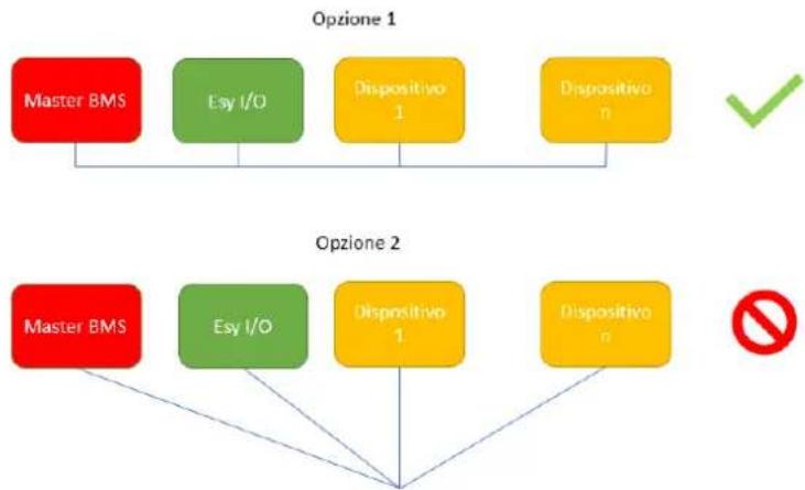
The typical connection with an RS485 BUS is shown below.
The recommended connection is always of the Daisy chain type (option 1). Do not use star (option 2) or ring connections. The termination resistors, if necessary, must be inserted in the first and last device on the bus (e.g. Figure 11: The termination resistors must be inserted in Master BMS and Device n) Figure 11: Examples of bus wiring.
The maximum recommended number of connected devices is 32, consistent with other devices in the network. The length of the cables depends on the baud rate chosen, i.e. the higher the baud rate, the shorter the cable length.
flowchart
graph TD
    subgraph Opzione 1
        A["Master BMS"] --> B["Esy I/O"]
        B --> C["Dispositivo 1"]
        C --> D["Dispositivo n"]
    end
    subgraph Opzione 2
        E["Master BMS"] --> F["Esy I/O"]
        F --> G["Dispositivo 1"]
        G --> H["Dispositivo n"]
    end
Figure 11: Examples of bus wiring
Parameter configuration
Esy I/O parameters are configured via Dconnect APP, connecting point-to-point via smartphone.
ENGLISH

The characteristics of the Modbus connection are as follows (the options at the first start-up are shown in bold):
| Parameter | Description | Settable values |
| Baud rate (bps) | Transmission speed | 2400, 4800, 9600, 19200, 38400, 57600, 115200 |
| Parity | Parity check | No, Even, Odd |
| Stop bit | Number of stop bits | 1.2 |
| Minimum response delay (ms) | Minimum response time (e.g., if 100, Esy I/O will respond to the message after at least 100ms) | 0 – 1000 |
| Id | Slave identification (each slave device on the Modbus network must have a different Id) | 1-247 |
Table 7: Modbus characteristics
For information on Modbus registers that can be consulted and/or modified, refer to the manual of the device connected to Esy I/O.
IMPORTANT! In order to use the Modbus peripheral, enable it via APP by configuring the Modbus Mode parameter.
2.11 Fault management
Table 8 Describes possible faults that may be encountered by Esy I/O.
| Fault | FAULT LED |
| General | On with fixed light |
| Insufficient supply voltage | 1 blink |
| Pressure sensor error (if sensor use is set) | 2 blinks |
| Internal error | 3... 7 blinks |
| Wireless | 8 blinks |
| Wifi | 9 blinks |
Table 8: List of faults
3. PROBLEM SOLVING
Before starting to look for faults due to the wiring it is necessary to disconnect the power supply to the pump (take the plug out of the socket).
Below is a list of possible problems:
| Problem | Problem description | Possible solution |
| Power led off | No power supply | Check power supply wiring |
| Check for short circuits due to incorrect wiring | ||
| Error Insufficient supply voltage | Board power supply voltage not sufficient | Check for overloads due to incorrect wiring of sensors, inputs and outputs |
| Pressure sensor error | Pressure sensor out of range | Check that the pressure sensor connection is correct (PR1 connector) |
| Green pressure sensor led not active | Although the pressure sensor is connected, the led does not work | Make sure the pressure sensor is enabled (proceed via APP) |
| Modbus communication not working | Modbus communication not working | If Modbus LED is GREEN:1) Check that Modbus is enabled, via APP (Modbus Mode parameter = enabled)2) Check that Modbus parameters are correct (Baud rate, parity, stop bits, ID), via APP3) Check RS485 wiringIf Modbus LED is RED:1) Make sure that wireless communication between pump/group and ESY I/O is active. |
FRANÇAIS
SOMMAIRE
- CONSIDÉRATIONS GÉNÉRALES 26
1.1 Contenu de l'emballage 26
1.2 Applications.... 26
- INSTALLATION....26
natural_image
Technical illustration of an electronic device showing internal components and a close-up view with labeled parts (no text or symbols present)- Revissez le panneau

Figure 3 : Écran principal APP Dconnect
ALLGEMEINE GEFAHRENSITUATION.
natural_image
Technical illustration of an electronic device showing internal components and a close-up view with labeled parts (no text or symbols present)- Volver a atornillar el panel

Figura 3: Pantalla principal APP Dconnect
- Привинтите панель
natural_image
Technical illustration of an electronic device showing internal components and a close-up view with labeled parts (no readable text or symbols)natural_image
Technical illustration of an electronic device showing internal components and a close-up view with labeled parts (no text or symbols present)Figura 2: Etiqueta Esy I/O
Figura 3: Tela principal APP Dconnect
INNEHÅLLSFÖRTECKNING
- ALLMÄN INFORMATION 134
natural_image
Technical illustration of an electronic device showing internal components and a close-up view with labeled parts (no text or symbols present)Fig. 2: Etikett Esy I/O
Figura 1: Imagine Frontala clame cabluri
Figura 3: Ecran principal APP Dconnect
natural_image
Technical illustration of an electronic device showing internal components and a close-up view with labeled parts (no text or symbols present)- ábra: Esy I/O cimke
206.1. Patient's emergency
"Dconnect" الشكل 3: her sheaisha her her her her her her her her her her her her her her her her her her her her her her her her her her her her her her her her her her her her her her her her her her her her her her her her her her her her her her her her her her her her her her her her her her her her her her her her her her her her her her her her her her her her her her her her her her her her her her her her her her her her Herer
| الحل المحتمل | وصف مشكلة | المشكلة |
| يجب التحقق من إمدادات الطاقة | مصر الطاقة غير متوفر | مؤسسة/DDالخاص بالطاقة مطفأ |
| يجب التحقق من وجود دوائر قصر بسب الأسلام غير الصحية | ||
| ينبغي التحقق من وجود أي حمولات زائدة Ses Festival岁以下ك المستثمعر والمداخل والمخارج | جهد إمداد الطاقة للوحة غير كافي | خطأ Equipment�فية إمدادات الطاقة |
| ينبغي التحقق من صحة توصيل مستثمعر الضغط (PRI موصل) | مستثمعر الضغط يمنح قيمة خارجNLنطاق | |
| يجب التاكن من تمكين مستثمعر الضغط (وَجِي APP المتابعة عير التطبيق) | إذا لم يكون مستثمعر الضغط متصلأ فلن يعمل مؤشرالليد | مؤسسة/DDال充电桩 auxضمر Privacy لبستثمعر الضغط غير شط |
| Macbusmodbusأ Grassة: (1Modbus) engineering閟 (2modbus) engineering閟 (3modbus) engineering閟 (4modbus) engineering閟 (5modbus) engineering閟 (6modbus) engineering閟 (7modbus) engineering閟 (8modbus) engineering閟 (9modbus) engineering閟 (10modbus) engineering閟 (11modbus) engineering閟 (12modbus) engineering閟 (13modbus) engineering閟 (14modbus) engineering閟 (15modbus) engineering閟 (16modbus) engineering閟 (17modbus) engineering閟 (18modbus) engineering閟 (19modbus) engineering閟 (20modbus) engineering閟 (21modbus) engineering閟 (22modbus) engineering閟 (23modbus) engineering閟 (24modbus) engineering閟 (25modbus) engineering閟 (26modbus) engineering閟 (27modbus) engineering閟 (28modbus) engineering閟 (29modbus) engineering閟 (30modbus) engineering閟 (31modbus) engineering閟 (32modbus) engineering閟 (33modbus) engineering閟 (34modbus) engineering閟 (35modbus) engineering閟 (36modbus) engineering閟 (37modbus) engineering閟 (38modbus) engineering閟 (39modbus) engineering閟 (40modbus) engineering閟 (41modbus) engineering閟 (42modbus) engineering閟 (43modbus) engineering閟 (44modbus) engineering閟 (45modbus) engineering閟 (46modbus) engineering閟 (47modbus) engineering閟 (48modbus) engineering閟 (49modbus) engineering閟 (50modbus) engineering閟 (51modbus) engineering閟 (52modbus) engineering閟 (53modbus) engineering閟 (54modbus) engineering閟 (55modbus) engineering閟 (56modbus) engineering閟 (57modbus) engineering閟 (58modbus) engineering閟 (59modbus) engineering閟 (60modbus) engineering閟 (61modbus) engineering閟 (62modbus) engineering閟 (63modbus) engineering閟 (64modbus) engineering閟 (65modbus) engineering閟 (66modbus) engineering閟 (67modbus) engineering閟 (68modbus) engineering閟 (69modbus) engineering閟 (70modbus) engineering閟 (71modbus) engineering閟 (72modbus) engineering閟 (73modbus) engineering閟 (74modbus) engineering閟 (75modbus) engineering閟 (76modbus) engineering閟 (77modbus) engineering閟 (78modbus) engineering閟 (79modbus) engineering閟 (80modbus) engineering閟 (81modbus) engineering閟 (82modbus) engineering閟 (83modbus) engineering閟 (84modbus) engineering閟 (85modbus) engineering閟 (86modbus) engineering閟 (87modbus) engineering閟 (88modbus) engineering閟 (89modbus) engineering閟 (90modbus) engineering閟 (91modbus) engineering閟 (92modbus) engineering閟 (93modbus) engineering閟 (94modbus) engineering閟 (95modbus) engineering閟 (96modbus) engineering閟 (97modbus) engineering閟 (98modbus) engineering閟 (99modbus) engineering閟 (100modbus) engineering閟 (101modbus) engineering閟 (102modbus) engineering閟 (103modbus) engineering閟 (104modbus) engineering閟 (105modbus) engineering閟 (106modbus) engineering閟 (107modbus) engineering閟 (108modbus) engineering閟 (109modbus) engineering閟 (110modbus) engineering閟 (111modbus) engineering閟 (112modbus) engineering閟 (113modbus) engineering閟 (114modbus) engineering閟 (115modbus) engineering閟 (116modbus) engineering閟 (117modbus) engineering閟 (118modbus) engineering閟 (119modbus) engineering閟 (120modbus) engineering閟 (121modbus) engineering閟 (122modbus) engineering閟 (123modbus) engineering閟 (124modbus) engineering閟 (125modbus) engineering閟 (126modbus) engineering閟 (127modbus) engineering閟 (128modbus) engineering閟 (129modbus) engineering閟 (130modbus) engineering閟 (131modbus) engineering閟 (132modbus) engineering閟 (133modbus) engineering閟 (134modbus) engineering閟 (135modbus) engineering閟 (136modbus) engineering閟 (137modbus) engineering閟 (138modbus) engineering閟 (139modbus) engineering閟 (140modbus) engineering閟 (141modbus) engineering閟 (142modbus) engineering閟 (143modbus) engineering閟 (144modbus) engineering閟 (145modbus) engineering閟 (146modbus) engineering閟 (147modbus) engineering閟 (148modbus) engineering閟 (149modbus) engineering閟 (150modbus) engineering閟 (151modbus) engineering閟 (152modbus) engineering閟 (153modbus) engineering閟 (154modbus) engineering閟 (155modbus) engineering閟 (156modbus) engineering閟 (157modbus) engineering閟 (158modbus) engineering閟 (159modbus) engineering閟 (160modbus) engineering閟 (161modbus) engineering閟 (162modbus) engineering閟 (163modbus) engineering閟 (164modbus) engineering閟 (165modbus) engineering閟 (166modbus) engineering閟 (167modbus) engineering閟 (168modbus) engineering閟 (169modbus) engineering閟 (170modbus) engineering閟 (171modbus) engineering閟 (172modbus) engineering閟 (173modbus) engineering閟 (174modbus) engineering閟 (175modbus) engineering閟 (176modbus) engineering閟 (177modbus) engineering閟 (178modbus) engineering閟 (179modbus) engineering閟 (180modbus) engineering閟 (181modbus) engineering閟 (182modbus) engineering閟 (183modbus) engineering閟 (184modbus) engineering閟 (185modbus) engineering閟 (186modbus) engineering閟 (187modbus) engineering閟 (188modbus) engineering閟 (189modbus) engineering閟 (190modbus) engineering閟 (191modbus) engineering閟 (192modbus) engineering閟 (193modbus) engineering閟 (194modbus) engineering閟 (195modbus) engineering閟 (196modbus) engineering閟 (197modbus) engineering閟 (198modbus) engineering閟 (199modbus) engineering閟 (200modbus) engineering閟 (201modbus) engineering閟 (202modbus) engineering閟 (203modbus) engineering閟 (204modbus) engineering閟 (205modbus) engineering閟 (206modbus) engineering閟 (207modbus) engineering閟 (208modbus) engineering閟 (209modbus) engineering閟 (210modbus) engineering閟 (211modbus) engineering閟 (212modbus) engineering閟 (213modbus) engineering閟 (214modbus) engineering閟 (215modbus) engineering閟 (216modbus) engineering閟 (217modbus) engineering閟 (218modbus) engineering閟 (219modbus) engineering閟 (220modbus) engineering閟 (221modbus) engineering閟 (222modbus) engineering閟 (223modbus) engineering閟 (224modbus) engineering閟 (225modbus) engineering閟 (226modbus) engineering閟 (227modbus) engineering閟 (228modbus) engineering閟 (229modbus) engineering閟 (230modbus) engineering閟 (231modbus) engineering閟 (232modbus) engineering閟 (233modbus) engineering閟 (234modbus) engineering閟 (235modbus) engineering閟 (236modbus) engineering閟 (237modbus) engineering閟 (238modbus) engineering閟 (239modbus) engineering閟 (240modbus) engineering閟 (241modbus) engineering閟 (242modbus) engineering閟 (243modbus) engineering閟 (244modbus) engineering閟 (245modbus) engineering閟 (246modbus) engineering閟 (247modbus) engineering閟 (248modbus) engineering閟 (249modbus) engineering閟 (250modbus) engineering閟 (251modbus) engineering閟 (252modbus) engineering閟 (253modbus) engineering閟 (254modbus) engineering閟 (255modbus) engineering閟 (256modbus) engineering閟 (257modbus) engineering閟 (258modbus) engineering閟 (259modbus) engineering閟 (260modbus) engineering閟 (261modbus) engineering閟 (262modbus) engineering閟 (263modbus) engineering閟 (264modbus) engineering閟 (265modbus) engineering閟 (266modbus) engineering閟 (267modbus) engineering閟 (268modbus) engineering閟 (269modbus) engineering閟 (270modbus) engineering閟 (271modbus) engineering閟 (272modbus) engineering閟 (273modbus) engineering閟 (274modbus) engineering閟 (275modbus) engineering閟 (276modbus) engineering閟 (277modbus) engineering閟 (278modbus) engineering閟 (279modbus) engineering閟 (280modbus) engineering閟 (281modbus) engineering閟 (282modbus) engineering閟 (283modbus) engineering閟 (284modbus) engineering閟 (285modbus) engineering閟 (286modbus) engineering閟 (287modbus) engineering閟 (288modbus) engineering閟 (289modbus) engineering閟 (290modbus) engineering閟 (291modbus) engineering閟 (292modbus) engineering閟 (293modbus) engineering閟 (294modbus) engineering閟 (295modbus) engineering閟 (296modbus) engineering閟 (297modbus) engineering閟 (298modbus) engineering閟 (299modbus) engineering閟 (300modbus) engineering閟 (301modbus) engineering閟 (302modbus) engineering閟 (303modbus) engineering閟 (304modbus) engineering閟 (305modbus) engineering閟 (306modbus) engineering閟 (307modbus) engineering閟 (308modbus) engineering閟 (309modbus) engineering閟 (310modbus) engineering閟 (311modbus) engineering閟 (312modbus) engineering閟 (313modbus) engineering閟 (314modbus) engineering閟 (315modbus) engineering閟 (316modbus) engineering閟 (317modbus) engineering閟 (318modbus) engineering閟 (319modbus) engineering閟 (320modbus) engineering閟 (321modbus) engineering閟 (322modbus) engineering閟 (323modbus) engineering閟 (324modbus) engineering閟 (325modbus) engineering閟 (326modbus) engineering閟 (327modbus) engineering閟 (328modbus) engineering閟 (329modbus) engineering閟 (330modbus) engineering閟 (331modbus) engineering閟 (332modbus) engineering閟 (333modbus) engineering閟 (334modbus) engineering閟 (335modbus) engineering閟 (336modbus) engineering閟 (337modbus) engineering閟 (338modbus) engineering閟 (339modbus) engineering閟 (340modbus) engineering閟 (341modbus) engineering閟 (342modbus) engineering閟 (343modbus) engineering閟 (344modbus) engineering閟 (345modbus) engineering閟 (346modbus) engineering閟 (347modbus) engineering閟 (348modbus) engineering閟 (349modbus) engineering閟 (350modbus) engineering閟 (351modbus) engineering閟 (352modbus) engineering閟 (353modbus) engineering閟 (354modbus) engineering閟 (355modbus) engineering閟 (356modbus) engineering閟 (357modbus) engineering閟 (358modbus) engineering閟 (359modbus) engineering閟 (360modbus) engineering閟 (361modbus) engineering閟 (362modbus) engineering閟 (363modbus) engineering閟 (364modbus) engineering閟 (365modbus) engineering閟 (366modbus) engineering閟 (367modbus) engineering閟 (368modbus) engineering閟 (369modbus) engineering閟 (370modbus) engineering閟 (371modbus) engineering閟 (372modbus) engineering閟 (373modbus) engineering閟 (374modbus) engineering閟 (375modbus) engineering閟 (376modbus) engineering閟 (377modbus) engineering閟 (378modbus) engineering閟 (379modbus) engineering閟 (380modbus) engineering閟 (381modbus) engineering閟 (382modbus) engineering閟 (383modbus) engineering閟 (384modbus) engineering閟 (385modbus) engineering閟 (386modbus) engineering閟 (387modbus) engineering閟 (388modbus) engineering閟 (389modbus) engineering閟 (390modbus) engineering閟 (391modbus) engineering閟 (392modbus) engineering閟 (393modbus) engineering閟 (394modbus) engineering閟 (395modbus) engineering閟 (396modbus) engineering閟 (397modbus) engineering閟 (398modbus) engineering閟 (399modbus) engineering閟 (400modbus) engineering閟 (401modbus) engineering閟 (402modbus) engineering閟 (403modbus) engineering閟 (404modbus) engineering閟 (405modbus) engineering閟 (406modbus) engineering閟 (407modbus) engineering閟 (408modbus) engineering閟 (409modbus) engineering閟 (410modbus) engineering閟 (411modbus) engineering閟 (412modbus) engineering閟 (413modbus) engineering閟 (414modbus) engineering閟 (415modbus) engineering閟 (416modbus) engineering閟 (417modbus) engineering閟 (418modbus) engineering閟 (419modbus) engineering閟 (420modbus) engineering閟 (421modbus) engineering閟 (422modbus) engineering閟 (423modbus) engineering閟 (424modbus) engineering閟 (425modbus) engineering閟 (426modbus) engineering閟 (427modbus) engineering閟 (428modbus) engineering閟 (429modbus) engineering閟 (430modbus) engineering閟 (431modbus) engineering閟 (432modbus) engineering閟 (433modbus) engineering閟 (434modbus) engineering閟 (435modbus) engineering閟 (436modbus) engineering閟 (437modbus) engineering閟 (438modbus) engineering閟 (439modbus) engineering閟 (440modbus) engineering閟 (441modbus) engineering閟 (442modbus) engineering閟 (443modbus) engineering閟 (444modbus) engineering閟 (445modbus) engineering閟 (446modbus) engineering閟 (447modbus) engineering閟 (448modbus) engineering閟 (449modbus) engineering閟 (450modbus) engineering閟 (451modbus) engineering閟 (452modbus) engineering閟 (453modbus) engineering閟 (454modbus) engineering閟 (455modbus) engineering閟 (456modbus) engineering閟 (457modbus) engineering閟 (458modbus) engineering閟 (459modbus) engineering閟 (460modbus) engineering閟 (461modbus) engineering閟 (462modbus) engineering閟 (463modbus) engineering閟 (464modbus) engineering閟 (465modbus) engineering閟 (466modbus) engineering閟 (467modbus) engineering閟 (468modbus) engineering閟 (469modbus) engineering閟 (470modbus) engineering閟 (471modbus) engineering閟 (472modbus) engineering閟 (473modbus) engineering閟 (474modbus) engineering閟 (475modbus) engineering閟 (476modbus) engineering閟 (477modbus) engineering閟 (478modbus) engineering閟 (479modbus) engineering閟 (480modbus) engineering閟 (481modbus) engineering閟 (482modbus) engineering閟 (483modbus) engineering閟 (484modbus) engineering閟 (485modbus) engineering閟 (486modbus) engineering閟 (487modbus) engineering閟 (488modbus) engineering閟 (489modbus) engineering閟 (490modbus) engineering閟 (491modbus) engineering閟 (492modbus) engineering閟 (493modbus) engineering閟 (494modbus) engineering閟 (495modbus) engineering閟 (496modbus) engineering閟 (497modbus) engineering閟 (498modbus) engineering閟 (499modbus) engineering閟 (500modbus) engineering閟 (501modbus) engineering閟 (502modbus) engineering閟 (503modbus) engineering閟 (504modbus) engineering閟 (505modbus) engineering閟 (506modbus) engineering閟 (507modbus) engineering閟 (508modbus) engineering閟 (509modbus) engineering閟 (510modbus) engineering閟 (511modbus) engineering閟 (512modbus) engineering閟 (513modbus) engineering閟 (514modbus) engineering閟 (515modbus) engineering閟 (516modbus) engineering閟 (517modbus) engineering閟 (518modbus) engineering閟 (519modbus) engineering閟 (520modbus) engineering閟 (521modbus) engineering閟 (522modbus) engineering閟 (523modbus) engineering閟 (524modbus) engineering閟 (525modbus) engineering閟 (526modbus) engineering閟 (527modbus) engineering閟 (528modbus) engineering閟 (529modbus) engineering閟 (530modbus) engineering閟 (531modbus) engineering閟 (532modbus) engineering閟 (533modbus) engineering閟 (534modbus) engineering閟 (535modbus) engineering閟 (536modbus) engineering閟 (537modbus) engineering閟 (538modbus) engineering閟 (539modbus) engineering閟 (540modbus) engineering閟 (541modbus) engineering閟 (542modbus) engineering閟 (543modbus) engineering閟 (544modbus) engineering閟 (545modbus) engineering閟 (546modbus) engineering閟 (547modbus) engineering閟 (548modbus) engineering閟 (549modbus) engineering閟 (550modbus) engineering閟 (551modbus) engineering閟 (552modbus) engineering閟 (553modbus) engineering閟 (554modbus) engineering閟 (555modbus) engineering閟 (556modbus) engineering閟 (557modbus) engineering閟 (558modbus) engineering閟 (559modbus) engineering閟 (560modbus) engineering閟 (561modbus) engineering閟 (562modbus) engineering閟 (563modbus) engineering閟 (564modbus) engineering閟 (565modbus) engineering閟 (566modbus) engineering閟 (567modbus) engineering閟 (568modbus) engineering閟 (569modbus) engineering閟 (570modbus) engineering閟 (571modbus) engineering閟 (572modbus) engineering閟 (573modbus) engineering閟 (574modbus) engineering閟 (575modbus) engineering閟 (576modbus) engineering閟 (577modbus) engineering閟 (578modbus) engineering閟 (579modbus) engineering閟 (580modbus) engineering閟 (581modbus) engineering閟 (582modbus) engineering閟 (583modbus) engineering閟 (584modbus) engineering閟 (585modbus) engineering閟 (586modbus) engineering閟 (587modbus) engineering閟 (588modbus) engineering閟 (589modbus) engineering閟 (590modbus) engineering閟 (591modbus) engineering閟 (592modbus) engineering閟 (593modbus) engineering閟 (594modbus) engineering閟 (595modbus) engineering閟 (596modbus) engineering閟 (597modbus) engineering閟 (598modbus) engineering閟 (599modbus) engineering閟 (600modbus) engineering閟 (601modbus) engineering閟 (602modbus) engineering閟 (603modbus) engineering閟 (604modbus) engineering閟 (605modbus) engineering閟 (606modbus) engineering閟 (607modbus) engineering閟 (608modbus) engineering閟 (609modbus) engineering閟 (610modbus) engineering閟 (611modbus) engineering閟 (612modbus) engineering閟 (613modbus) engineering閟 (614modbus) engineering閟 (615modbus) engineering閟 (616modbus) engineering閟 (617modbus) engineering閟 (618modbus) engineering閟 (619modbus) engineering閟 (620modbus) engineering閟 (621modbus) engineering閟 (622modbus) engineering閟 (623modbus) engineering閟 (624modbus) engineering閟 (625modbus) engineering閟 (626modbus) engineering閟 (627modbus) engineering閟 (628modbus) engineering閟 (629modbus) engineering閟 (630modbus) engineering閟 (631modbus) engineering閟 (632modbus) engineering閟 (633modbus) engineering閟 (634modbus) engineering閟 (635modbus) engineering閟 (636modbus) engineering閟 (637modbus) engineering閟 (638modbus) engineering閟 (639modbus) engineering閟 (640modbus) engineering閟 (641modbus) engineering閟 (642modbus) engineering閟 (643modbus) engineering閟 (644modbus) engineering閟 (645modbus) engineering閟 (646modbus) engineering閟 (647modbus) engineering閟 (648modbus) engineering閟 (649modbus) engineering閟 (650modbus) engineering閟 (651modbus) engineering閟 (652modbus) engineering閟 (653modbus) engineering閟 (654modbus) engineering閟 (655modbus) engineering閟 (656modbus) engineering閟 (657modbus) engineering閟 (658modbus) engineering閟 (659modbus) engineering閟 (660modbus) engineering閟 (661modbus) engineering閟 (662modbus) engineering閟 (663modbus) engineering閟 (664modbus |
DAB PUMPS LTD.
6 Gilbert Court
Newcomen Way
Severalls Business Park
Colchester
Essex
C04 9WN - UK
salesuk@dwtgroup.com
Tel. +44 0333 777 5010
DAB PUMPS BV
'tHofveld 6 C1
info.belgium@dwtgroup.com
Tel. +32 2 4668353
DAB PUMPS INC.
3226 Benchmark Drive
Ladson, SC 29456 - USA
info.usa@dwtgroup.com
Tel. 1-843-797-5002
Fax 1-843-797-3366
000 DAB PUMPS
Novgorodskaya str. 1, block G
office 308, 127247, Moscow - Russia
info.russia@dwtgroup.com
Tel. +7 495 122 0035
Fax +7 495 122 0036
DAB PUMPS POLAND SP. z.o.o.
No.40 Kaituo Road, Qingdao Economic &
Technological Development Zone
Qingdao City, Shandong Province - China
PC: 266500
sales.cn@dwtgroup.com
Tel. +86 400 186 8280
Fax +86 53286812210
DAB PUMPS IBERICA S.L.
Calle Verano 18-20-22
28850 - Torrejón de Ardoz - Madrid
Spain
Info.spain@dwtgroup.com
Tel. +34 91 6569545
Fax: + 34 91 6569676
DAB PUMPS B.V.
Twenty One industrial Estate,
16 Purlin Street, Unit B, Warehouse 4
Olifantsfontein - 1666 - South Africa
info.sa@dwtgroup.com
Tel. +27 12 361 3997
DAB PUMPS GmbH
Am Nordpark 3
41069 Mönchengladbach, Germany
info.germany@dwtgroup.com
Tel. +49 2161 47 388 0
Fax +49 2161 47 388 36
DAB PUMPS HUNGARY KFT.
H-8800
Nagykanizsa, Buda Ernő u.5
Hungary
Tel. +36 93501700
426 South Gippsland Hwy,
Dandenong South VIC 3175 – Australia
info.oceania@dwtgroup.com
Tel. +61 1300 373 677

WATER•TECHNOLOGY
DAB PUMPS S.p.A.
Via M. Polo, 14 - 35035 Mestrino (PD) - Italy
Tel. +39 049 5125000 - Fax +39 049 5125950
www.dabpumps.com


- KEY
- WARNINGS
- Skilled personnel
- ENGLISH
- Safety
- Particular warnings
- GENERAL
- Content of the pack
- Applications
- INSTALLATION
- Electrical connections
- Product characteristics
- User interface
- Local connection via APP
- Updating the software
- Dab Proprietary Wireless connection
- Proprietary wireless connection procedure
- Optoisolated digital inputs
- Output contacts
- Remote pressure sensor
- RS485 Modbus RTU connection
- Wiring
- Parameter configuration
- Fault management
- PROBLEM SOLVING
- FRANÇAIS
- SOMMAIRE
- ALLGEMEINE GEFAHRENSITUATION.
- INNEHÅLLSFÖRTECKNING
- DAB PUMPS LTD.
- DAB PUMPS BV
- DAB PUMPS INC.
- DAB PUMPS
- DAB PUMPS POLAND SP. z.o.o.
- DAB PUMPS IBERICA S.L.
- DAB PUMPS B.V.
- DAB PUMPS GmbH
- DAB PUMPS HUNGARY KFT.
- DAB PUMPS S.p.A.
Brand : DAB
Model : ESY I/O
Category : Water pump