
JetCom - Water pump DAB - Free user manual and instructions
Find the device manual for free JetCom DAB in PDF.


| Product type | Self-priming centrifugal jet pump |
| Applications | Water supply, rural household pressure boosting, irrigation, domestic emergencies, industrial services |
| Pumped liquids | Clean water, free of solid particles, chemically non-aggressive |
| Supply voltage | 1 × 115/230 V, 60 Hz |
| Power consumption | See electrical data plate |
| Flow rate | 0.4 to 17.2 m³/h |
| Maximum delivery head | 72 m |
| Maximum working pressure | 6 bar (600 kPa) |
| Maximum liquid temperature | 0 to +35 °C (domestic use) |
| Motor class | F |
| Storage temperature | -10 °C to +40 °C |
| Maximum relative humidity | 95% |
| Installation | Ventilated area, protected from weather, ambient temperature ≤ 40 °C, horizontal position |
| Electrical connection | By qualified electrician, mandatory grounding, built-in thermal protection |
| Priming | Fill the pump completely with water before each start |
| Frost protection | Drain the pump completely if inactive at temperature < 0 °C |
| Maintenance | No routine maintenance required; wash hydraulic parts if performance drops |
| Spare parts | Use only original parts approved by the manufacturer |
| Repairs | Entrust to specialized and qualified personnel |
Frequently Asked Questions - JetCom DAB
User questions about JetCom DAB
0 question about this device. Answer the ones you know or ask your own.
Ask a new question about this device
Download the instructions for your Water pump in PDF format for free! Find your manual JetCom - DAB and take your electronic device back in hand. On this page are published all the documents necessary for the use of your device. JetCom by DAB.
USER MANUAL JetCom DAB
INSTRUCTIONS FOR INSTALLATION AND MAINTENANCE INSTRUCTIONS POUR L'INSTALLATION ET LA MAINTENANCE INSTRUCCIONES PARA LA INSTALACION Y EL MANTENIMIENTO
JET - JETINOX - JETCOM
EURO - EUROINOX - EUROCOM
K
DP
| CONTENTS | page | |
| 1. | GENERAL | |
| 2. | APPLICATIONS | 1 |
| 3. | PUMPED FLUIDS | 1 |
| 4. | TECHNICAL DATA AND RANGE OF USE | 1 |
| 5. | MANAGEMENT | 2 |
| 5.1. | Storage | 2 |
| 5.2. | Transport | 2 |
| 5.3. | Weights | 2 |
| 6. | WARNING | 2 |
| 6.1. | Skilled personnel | 2 |
| 6.2. | Safety | 2 |
| 6.3. | Checking motor shaft rotation | 2 |
| 6.4. | Responsibility | 2 |
| 7. | INSTALLATION | 3 |
| 8. | ELECTRICAL CONNECTION | 3 |
| 9. | STARTING UP | 4 |
| 10. | PRECAUTIONS | 4 |
| 11. | MAINTENANCE AND CLEANING | 4 |
| 12. | MODIFICATIONS AND SPARE PARTS | 4 |
| 12.1 | Removal and replacement of the supply cable | 4 |
| 13. | INSTRUCTIONS FOR ADJUSTING THE PRESSURE SWITCH | 4 |
| 14. | TROUBLESHOOTING | 5 |
1. GENERAL

Read this documentation carefully before installation. Installation and functioning must comply with the safety regulations in the country in which the product is installed. The entire operation must be carried out in a workmanlike manner.
Failure to comply with the safety regulations not only causes risk to personal safety and damage to the equipment, but invalidates every right to assistance under guarantee.
2. APPLICATIONS
JET - JETINOX - JETCOM: Self-priming centrifugal jet pumps with excellent suction capacity, even when gas is present in the water. Particularly suitable for water supply uses and for pressurization in the home. Suitable for small farming applications, market gardens, gardening, emergencies in the home and industrial utilities.
EURO - EUROINOX - EUROCOM: Self-priming multistage centrifugal pump with horizontal action, suitable for domestic or industrial uses, for water supply systems and pressurization. In farming it is ideal for small irrigation work and for washing tools and machinery. Also suitable for water containing gas. Water is recycled only during the priming stage, after which the maximum flow is made available for use with continuous and constant distribution. These qualities allow vast possibilities for use.
K : Single impeller centrifugal pump designed for domestic, civil, industrial and agricultural installations and for decanting, mixing and irrigating uses.
DP: Self-priming centrifugal pumps for suction at depths of as many as 30 metres with ejector to be fitted in 4^ wells or larger. Used for supplying water to farm houses and in small farming applications.
3. PUMPED FLUIDS

The machine has been designed and built for pumping water, free from explosive substances and solid particles or fibres, with a density of 61,31 lb/ft³ and a kinematic viscosity of 1,0764 × 10^-5 ft^2/s , and chemically non-aggressive liquids.
4. TECHNICAL DATA AND RANGE OF USE
| - Supply voltage: | 1 X 115/230V 60Hz see electrical data plate |
| - Absorbed power: | see electrical data plate |
| - Delivery: | from 0,4 to 17,2 m³/h From 1.7 to 75 gpm |
| - Head up: | to 72 m. 236 ft |
| - Pumped liquid: | clean, free from solid bodies or abrasive substances, non-aggressive. |
| - Protection class: | F |
ENGLISH
| - Maximun operating pressure: | 88 psi (6 bar) (600 kPa): | JETCOM EURO-EUROINOX-EUROCOM K DP |
| 116 psi (8 bar) (800 kPa): | JET-JETINOX | |
| - Liquid temperature range: | 32 - 95 °F \( 0 \div {35}^{ \circ }\mathrm{C} \) : | For all homologated pumps EN 60335-2-41 (for domestic uses) |
| 32 -104 °F \( 0 \div {40}^{ \circ }\mathrm{C} \) : | JET-JETINOX-JETCOM DP | |
| \( - {10} \div + {50}^{ \circ }\mathrm{C} : \mathrm{K} \) |
- Storage temperature: 14 - 104°F (-10°C to 40°C)
- Relative humidity of the air: MAX. 95%
5. MANAGEMENT
5.1 Storage
All the pumps must be stored indoors, in a dry, vibration-free and dust-free environment, possibly with constant air humidity. They are supplied in their original packaging and must remain there until the time of installation. If this is not possible, the intake and discharge ports must be accurately closed.
5.2 Transport
Avoid subjecting the products to needless jolts or collisions.
To lift and transport the unit, use lifting equipment and the pallet supplied standard (if applicable).
5.3 Weights
The adhesive label on the package indicates the total weight of the pump.
6. WARNINGS
6.1 Skilled technical personnel

It is advisable that installation be carried out by skilled personnel in possession of the technical qualifications required by the specific legislation in force.
The term skilled personnel means persons whose training, experience and instruction, as well as their knowledge of the respective standards and requirements for accident prevention and working conditions, have been approved by the person in charge of plant safety, authorizing them to perform all the necessary activities, during which they are able to recognize and avoid all dangers.
6.2 Safety
Use is allowed only if the electric system is in possession of safety precautions in accordance with the regulations in force in the country where the product is installed.
6.3 Checking motor shaft rotation
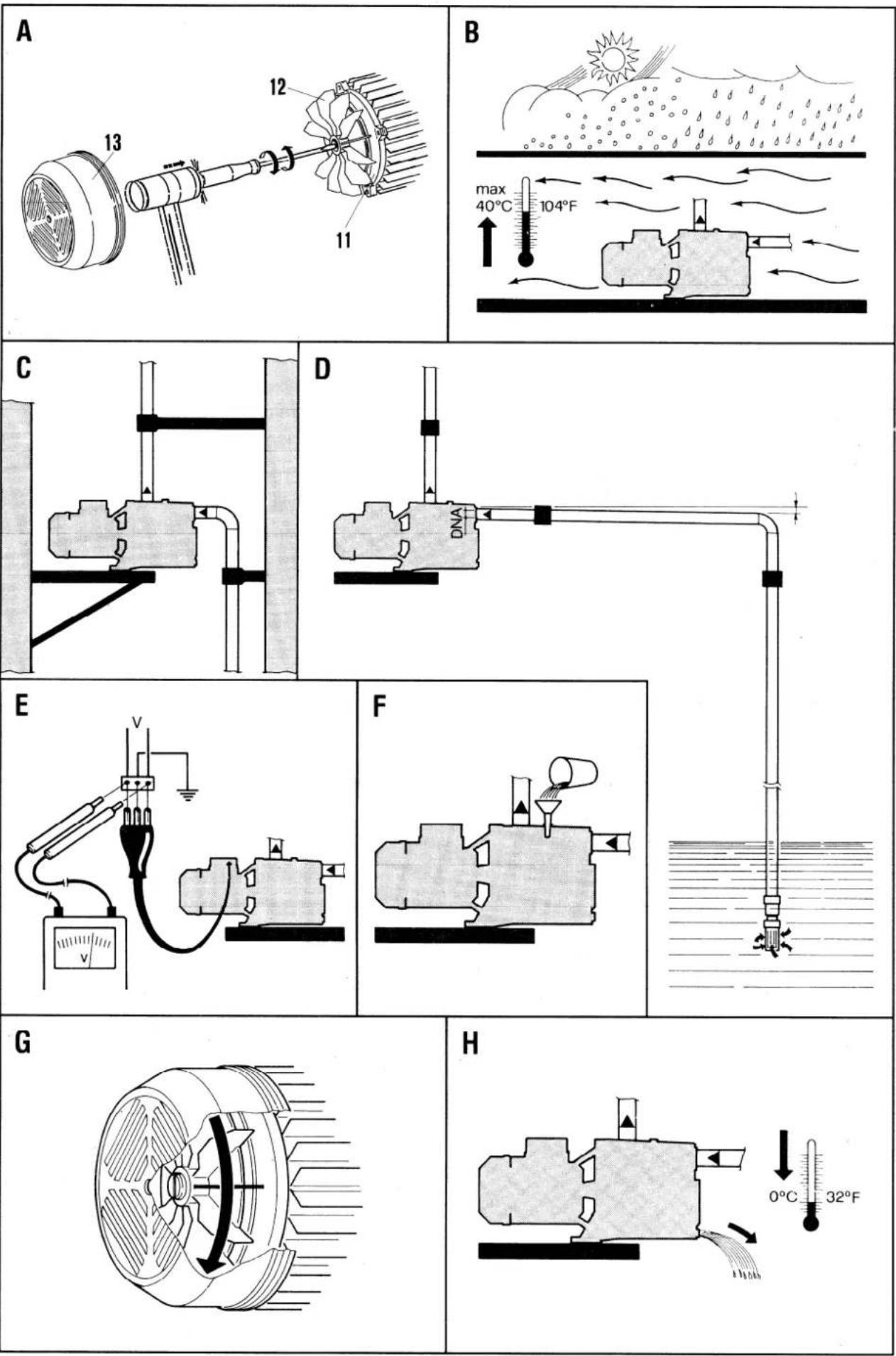
Before installing the pump you must check that the rotating parts turn freely. For this purpose remove the fan cover from its seat in the motor end cover. Insert a screwdriver in the notch on the motor shaft from the ventilation side. If there is a blockage, turn the screwdriver, tapping it gently with a hammer. Fig.A
6.4 Responsibility
| The Manufacturer does not vouch for correct operation of the pumps if they are tampered with or modified, run outside the recommended work range or in contrast with the other instructions given in this manual. The Manufacturer declines all responsibility for possible errors in this instructions manual, if due to misprints or errors in copying. The company reserves the right to make any modifications to products that it may consider necessary or useful, without affecting the essential characteristics. |
7. INSTALLATION
7.1 The pump must be fitted in a well ventilated place, protected from unfavorable weather conditions and with an environment temperature not exceeding 104^ (40^) . Fig.B
7.2 A firm anchoring of the pump to the bearing surface favors the absorption of any vibrations caused by pump operation. Fig. C
7.3 Ensure that the metal pipes do not exert undue strain on the apertures, thus preventing deformations or breakages. Fig. C
7.4 It is always good practice to place the pump as close as possible to the liquid to be pumped. The pump must be installed only in horizontal position. The internal diameters of the pipes must never be smaller than that of the mouth of the pump. It is advisable to fit a foot valve on suction. Fig. D For suction depths of over 13ft (4 m), or with long horizontal stretches it is advisable to use an intake hose with a diameter larger than that of the intake aperture of the pump. To prevent the formation of air pockets, the intake hose must slope slightly upwards towards the pump. Fig. D
7.5 If the intake pipe is made of rubber or flexible material, always check that it is of the reinforced type to avoid throttling due to suction.
8. ELECTRICAL CONNECTION
Caution! always follow the safety regulations.
Please follow the wiring diagrams inside the pressure box.
8.1 All electrical work should be performed by a qualified electrician in accordance with the latest edition of the National Electrical Code, local codes and regulations.
Ensure that the mains voltage is the same as the value shown on the motor plate. A faulty motor or winding can cause electrical shock that could be fatal, whether touched directly or conducted through standing water. For this reason, proper grounding of the pump to the power supply's grounding terminal is required for safe installations, the above-ground metal plumbing should be connected to the power supply as a ground as described in Article 250-80 of the National Electrical Code or Section 26-954 of the Canadian.
8.2 In fixed installations, International Safety Standards require the use of isolating switches with a fuse-carrier base.
8.3 Single-phase motors are provided with built-in thermal overload protection with automatic reset, and may be connected directly to the mains.
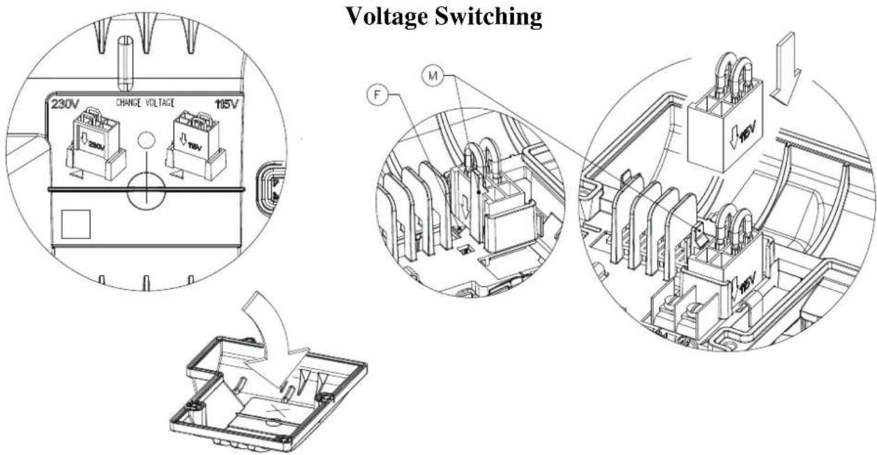
FITTING THE VOLTAGE CONVERTER
- Check the voltage indicated on the side of the voltage converter.
- Turn the indicator so that the desired voltage points towards the side with the "M" lock catch.
- The arrow on the converter next to the required voltage must be aligned with the "F" arrow on the housing.
Push the converter into position until the reference catch "M" clips in place.
9. STARTING UP
9.1

Do not start the pump unless it has been completely filled with fluid.
Before starting up, check that the pump is properly primed; fill it completely with clean water by means of the hole provided after having removed the filler cap on the pump body. This ensures that the mechanical seal is well lubricated and that the pump immediately starts to work regularly. (Fig. F). Dry operation causes irreparable damage to the mechanical seal. The filling cap must then be screwed back on carefully.
10. PRECAUTIONS
10.1 The pump should not be started more than 20 times in one hour so as not to subject the motor to excessive thermal shock.
10.2 DANGER OF FROST: When the pump remains inactive for a long time at temperatures of less than 32^ (0^) , the pump body must be completely emptied through the drain cap Fig. H, to prevent possible cracking of the hydraulic components. This operation is advisable even in the event of prolonged inactivity at normal temperature.
10.3 When starting after long periods of inactivity, the starting-up operations listed above must be repeated.
11. MAINTENANCE AND CLEANING

In normal operation, the pump does not require any specific maintenance. However, it may be necessary to clean the hydraulic parts when a decrease in performance is observed. The pump must not be dismantled unless by skilled personnel in possession of the qualifications required by the regulations in force. In any case, all repairs and maintenance jobs must be carried out only after having disconnected the pump from the power mains.
12. MODIFICATIONS AND SPARE PARTS

Any modification not authorized beforehand relieves the manufacturer of all responsibility. All the spare parts used in repairs must be original ones and the accessories must be approved by the manufacturer so as to be able to guarantee maximum safety of the machines and systems in which they may be fitted.
12.1 Removal and replacement of the supply cable

Before starting, ensure that the pump is not connected to the power network
Unscrew the screw from the cover of the pressure switch using a screwdriver and remove the cover. Remove the yellow-green lead, slackening the earth screw, the blue lead and the brown lead from the respective terminals at the side, slackening the screws on the terminals. Remove the cable blocking terminal, slackening the respective screws, and slip off the cable which is now disconnected.
When replacing the power cable, a cable of the same type must be used and with the same terminals, proceeding as for disassembly in inverse order.
ATTENTION:
For power cables with a plug, fit a device for disconnecting the power network (e.g. a magnetothermal switch) with separation contacts of at least 0.12^ . for each pole.
13. INSTRUCTIONS FOR ADJUSTING THE PRESSURE SWITCH
- Establish the minimum desired pressure value (leaving the pump).
- Set the storage tank pre-loading pressure 42 psi (2.9 bar) less than the minimum pressure level.
-
Calibrate it following the indications given below inside the pressure box.
-
TROUBLESHOOTING
| FAULT | CHECKS (possible cause) | REMEDY |
| 1. The motor does not start and makes no noise. | A. Check the electric connections.B. Check that the motor is live.C. Check the protection fuses.D. Check that the pressure switch is live.E. Ensure that the tank preloading pressure is not higher than the minimum value of the pressure switch. | C. If t hey are burnt-out, change them.N.B. If the fault is repeated immediately this means that the motor is short circuiting.E. Set the preloading pressure 2,9 bar belo w the minimum value of the pressure switch. |
| 2. The motor does not start but makes noise. | A. En sure that the mains voltage is the same as the value on the plate.B. Ensure t hat the connections have been made correctly.C. Check that all the phases are present on the terminal board. (3~)D. Look for poss ble blockages in the pump or motor.E. Check the condition of the capacitor. | B. Correct any errors.C. If not , restore the missing phase.D. R remove the blockage.E. Replace the capacitor. |
| 3. The motor turns with difficulty. | A. Check the voltage which may be insufficient.B. Check whether any moving parts are scraping against fixed parts. | B. Eliminate the cause of the scraping. |
| 4. The pump does not deliver. | A. The pump has not been primed correctly.B. The diameter of the intake pipe is insufficient.C. B locked foot valve. | B. Replace the pipe with a larger diameter one.C. Clean the foot valve. |
| 5. The pump does not prime. | A. The intake pipe or the foot valve is taking in air.B. The downward sl ope of the intake pipe favours the formation of air pockets. | A. Correct the problem and prime again.B. Co rrect the inclination of the intake pipe. |
| 6. The pump supplies insufficient flow. | A. Linked foot valve.B. The i mpeller is worn or blocked.C. The diameter of the intake pipe is insufficient. | A. Clean the foot valve.B. Rem ove the obstructions or replace the worn parts.C. Replace the pipe with one with a larger diameter. |
| 7. The pump vibrates and operates noisily. | A. Check that the pump and the pipes are firmly anchored.B. Th ere is cavitation in the pump, that is the demand for water is higher than it is able to pump.C. The pump is running above its plate characteristics. | A. Fix the loose parts m ore carefully.B. Reduce the intake height or check for load losses.C. It may be useful to limit the flow at delivery. |
| 8. The motor does noy stop when the demand for water has ceased. | A. En sure that the value at which the pressure switch is set to stop the motor is not higher than the pressure than the pump can generate (suction + delivery)B. Check that the pressure switch contacts move freely. | A. Set the pressure switch at a lo wer pressure.B. Ot herwise change the pressure switch. |
| 9. The pressure switch, starting and stopping frequently during normal water delivery. | A. Check the setting of the pressure switch which witt certainly be too low.B. Check that the diaphragm of the expansion chamber (if used) is unbroken. | A. Increase the setting values of the pressure switch until the problem is overcome. Do not forget to reset the minimun intervention pressure.B. Oth erwise remove the fault. |
| TABLE DES MATIÈRES page | ||
| 1. | GÉNÉRALITÉS | 7 |
| 2. | APPLICATIONS | 7 |
| 3. | LIQUIDES POMPES | 7 |
| 4. | CARACTERISTIQUES TECHNIQUES ET LIMITES D'UTILISATION | 7 |
| 5. | GESTION | 9 |
| 5.1. | Stockage | 9 |
| 5.2. | Transport | 9 |
| 5.3. | Poids | 9 |
| 6. | AVERTISSEMENTS | 9 |
| 6.1. | Personnel spécifique | 9 |
| 6.2. | Sécurité | 9 |
| 6.3. | Contrôle rotation arbre moteur | 9 |
| 6.4 | Responsabilités | 9 |
| 7. | INSTALLATION | 9 |
| 8. | BRANCHEMENT ÉLECTRIQUE | 10 |
| 9. | MISE EN MARCHE | 11 |
| 10. | PRECAUTIONS | 11 |
| 11. | MAINTENANCE ET LAVAGE | 11 |
| 12. | MODIFICATIONS ET PIEÇES DE RECHANGE | 11 |
| 12.1 | Enlèvement et remplacement du cable | 11 |
| 13. | INSTRUCIONS POUR LE REGLAGE DES CONTACTEURS-MANO | 11 |
| 14. | IDENTIFICATION DES INCONVÉNIENTS ET REMÉDES | 12 |
1. GÉNÉRALITÉS

6.4 Responsibilities


- INSTRUCTIONS FOR INSTALLATION AND MAINTENANCE INSTRUCTIONS POUR L'INSTALLATION ET LA MAINTENANCE INSTRUCCIONES PARA LA INSTALACION Y EL MANTENIMIENTO
- GENERAL
- APPLICATIONS
- PUMPED FLUIDS
- TECHNICAL DATA AND RANGE OF USE
- MANAGEMENT
- Storage
- Transport
- Weights
- WARNINGS
- Skilled technical personnel
- Safety
- Checking motor shaft rotation
- Responsibility
- INSTALLATION
- ELECTRICAL CONNECTION
- Please follow the wiring diagrams inside the pressure box.
- FITTING THE VOLTAGE CONVERTER
- STARTING UP
- Do not start the pump unless it has been completely filled with fluid.
- PRECAUTIONS
- MAINTENANCE AND CLEANING
- MODIFICATIONS AND SPARE PARTS
- Removal and replacement of the supply cable
- Before starting, ensure that the pump is not connected to the power network
- ATTENTION:
- INSTRUCTIONS FOR ADJUSTING THE PRESSURE SWITCH
- GÉNÉRALITÉS
- Responsibilities
Brand : DAB
Model : JetCom
Category : Water pump