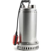
DRENAG 1000-1200 - Water pump DAB - Free user manual and instructions
Find the device manual for free DRENAG 1000-1200 DAB in PDF.


| Product type | Submersible water pump for clean or dirty water |
| Brand | DAB |
| Model | DRENAG 1000-1200 |
| Power supply | Single-phase 220-240 V 50/60 Hz or three-phase 400 V 50 Hz / 230 V 60 Hz depending on version |
| Motor protection | Built-in amperometric thermal protection (single-phase); calibrated circuit breaker required (three-phase) |
| Maximum immersion | 10 meters |
| Liquid temperature range | 0 °C to +35 °C (domestic use); 0 °C to +50 °C (other uses) |
| Storage temperature | -10 °C to +40 °C |
| Sound level | Compliant with EC directive 89/392/EEC |
| Main functions | Pumping clean or dirty water (sand, mud); draining sumps, basements, construction sites; automatic operation with float switch |
| Float switch | Adjustable (cable length) for START/STOP levels; do not uncover the filter |
| Installation | Place on support if bottom is dirty; use hose Ø ≥ discharge flange; immerse completely; for fixed installation, provide check valve |
| Maintenance and cleaning | Rinse after use with depositing substances; drain oil from mechanical seal every 170 g (type MARCOL 152); no routine maintenance |
| Precautions | Do not run dry; max 20 starts/hour; drain if frost risk; do not pump hydrocarbons or in presence of bathers |
| Spare parts and repairability | Impeller, mechanical seal, O-rings, power cable (type H07RN-F); replacement by qualified personnel |
| General information | Manual available in PDF; 8 pages; weight not specified, dimensions not specified |
Frequently Asked Questions - DRENAG 1000-1200 DAB
User questions about DRENAG 1000-1200 DAB
0 question about this device. Answer the ones you know or ask your own.
Ask a new question about this device
Download the instructions for your Water pump in PDF format for free! Find your manual DRENAG 1000-1200 - DAB and take your electronic device back in hand. On this page are published all the documents necessary for the use of your device. DRENAG 1000-1200 by DAB.
USER MANUAL DRENAG 1000-1200 DAB
INSTRUCTIONS DE MISE EN SERVICE ET D'ENTRETIEN (FR) INSTRUCTIONS FOR INSTALLATION AND MAINTENANCE (EN)
DRENAG 1000-1200
natural_image
Line drawing of a portable water purifier with hose and control panel (no text or symbols)CONTENTS
- LIQUIDES POMPES ....4
- CARACTERISTIQUES TECHNIQUES ET LIMITES D'UTILISATION ....4
- AVERTISSEMENTS......4
- INSTALLATION ....4
- BRANCHEMENT ELECTRIQUE ....5
- CONTROLE DU SENS DE ROTATION (pour moteurs triphasés)....5
- MISE EN MARCHE ....5
- PUMPED FLUIDS 7
- TECHNICAL DATA AND LIMITS ON USE....7
- WARNINGS....7
- INSTALLAZIONE....7
- ELECTRIC CONNECTION......8
- CHECKING THE DIRECTION OF ROTATION (for three-phase motors)....8
- STARTING UP 8
Adjusting the float switch....8
- PRECAUTIONS....8
- MAINTENANCE AND CLEANING....8
Checking and changing the sealing oil....8
- TROUBLESHOOTING 9
1. PUMPED FLUIDS

These pumps cannot be used in swimming pools, ponds or tanks in which people or present, or for pumping hydrocarbons (petrol, diesel fuel, fuel oils, solvents, etc.) in accordance with the accident-prevention regulations in force.
N.B.: The liquid inside the pump, to lubricate the seal device, is not toxic but it may alter the characteristics of the water (if it is pure water) if there is a leak in the seal device.
2. TECHNICAL DATA AND LIMITS ON USE
1 X 220/240V 50Hz 1 X 220/230V 60Hz
— Supply voltage: 3 X 400V 50Hz 3 X 230V 60Hz
3 X 230V 50Hz 3 X 380/400V 60Hz
see electric data plate
— Flow rate: see electric data plate
— Hmax (m) - Head: 57 ft (17.5 m)
— Degree of motor protection / Protection class: see electric data plate
— Absorbed power: see electric data plate
– from 32°F - 95°F (0°C to +35°C) for domestic use (safety standards EN 60335-2-41)
— Liquid temperature range: — from 32^ F - 122^ F ( 0^ C to +50^ C) for other uses
— Maximum immersion: 32.8 ft (10 m).
— Storage temperature: 14°F - 104°F (-10°C +40°C)
— Noise level: Falls within the limits envisaged by EC Directive 89/392/EEC and subsequent modifications.
3. WARNINGS
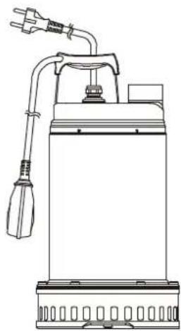
— The pump is provided with a carrying handle which may also be used to lower it into wells or deep holes with a rope or cable.
- If the power cable is damaged in any way it must be replaced and not repaired (use cable type H07RN-F diam. 9 – 9.5 mm. with minimum length 10 metres for the portable version, with a UNEL 47166-68 plug for the SINGLE-PHASE version and with an EEC plug for the THREE-PHASE version). This must be done by skilled personnel, in possession of the qualifications required by the regulations in force.
- T he pump must never be allowed to run dry.
4. INSTALLAZIONE
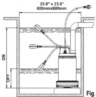
4.1 If the bottom of the well or borehole in which the pump is to operate is particularly dirty, it is advisable to provide a support for the pump to sit on so as to avoid clogging of the intake grid (Fig.1).
4.2 Before putting the pump in position, ensure that the strainer is not totally or partially blocked by mud, sediment or similar substances.
4.3 It is advisable to use pipes with an internal diameter at least equal to that of the delivery mouth, to avoid falls in pump performance and the possibility of clogging. In cases where the delivery pipe has long horizontal stretches, it is advisable for this pipe to have a larger diameter than that of the delivery mouth.

Totally immerse the pump in the water.
4.4
- Connect the delivery pipe or hose directly to the pump mouth. If the pump is used in fixed installations it is advisable to connect it to the pipe with a coupling so as to facilitate disassembly and reinstallation. If a hose is used, fit a threaded hosetail on the pump mouth. Wrap the thread with suitable material to ensure an effective seal (teflon tape or similar).
- On the version provided with a float switch, ensure that the float can move freely (SEE THE PARAGRAPH ON ADJUSTING THE FLOAT SWITCH). Ensure that the minimum dimensions of the borehole are as in Fig.1. The dimensions of the borehole must also be calculated with relation to the quantity of water arriving and to the pump flow rate so as not to subject the motor to excessive starting operations.
- When the pump is to be in a fixed installation, with a float, a check valve must always be fitted in the delivery pipe. This is also advisable on pumps with manual operation.
5. ELECTRIC CONNECTION

Caution: always follow the safety regulations!
5.1 Single-phase motors are provided with built-in thermal overload protection and may be connected directly to the mains. N.B. If the motor is overloaded it stops automatically. Once it has cooled down it starts again automatically without any need for manual intervention.
5.2 Three-phase pumps must be protected with motor protectors suitably calibrated according to the values on the data plate of the pump to be installed.
5.3 Do not damage or cut the power cable. If this should occur accidentally, have it repaired or replaced by skilled and qualified personnel.
6. CHECKING THE DIRECTION OF ROTATION (for three-phase motors)
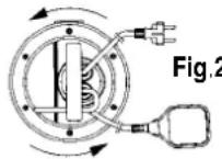
The direction of rotation must be checked each time a new installation is made.
Proceed as follows (Fig.2):
- Place the pump on a flat surface.
-
Start the pump and stop it immediately.
-
Carefully observe the kick-back on starting, looking at the pump from the motor side. The direction of rotation is correct, that is clockwise, if the protection cap moves as in the drawing (anti-clockwise).
If it is not possible to check as described above because the pump is already installed, check as follows:
- Start the pump and observe the water flow rate.
- Stop the pump, switch off the power and invert two phases on the supply line.
- Restart the pump and check the water flow rate again.
- Stop the pump.

The correct direction of rotation will be the one in which the flow rate and electric absorption are LOWER!
7. STARTING UP
Models with a float switch start up automatically when the water level rises; models without a float are started by means of a switch located upstream from the socket (not supplied).
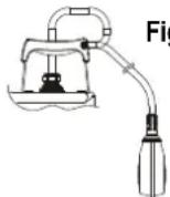
Adjusting the float switch
Fig.3
Lengthening or shortening the cable between the float and the fixed point (slot provided in the handle - Fig.3) adjusts the START or STOP level of the pump. Be sure that the float can move freely.

Ensure that the stop level does not uncover the strainer.
8. PRECAUTIONS
8.1 The intake strainer must always be in place during pump operation.
8.2 The pump should not be started more than 20 times in one hour so as not to subject the motor to excessive thermal shock.
8.3 DANGER OF FROST: When the pump remains inactive for a long time at temperatures of less than 0^ C, it is necessary to ensure that there is no water residue which could freeze and cause cracking of the pump components.
8.4 If the pump has been used with substances which tend to form a deposit, rinse it after use with a powerful jet of water so as to avoid the formation of deposits or scale which would tend to reduce the yield of the pump.
8.5

Connect pumps that are delivered without cable and/or plugs to an external mains switch with a minimum contact gap of 0.12" / 3 mm in all poles.
9. MAINTENANCE AND CLEANING

In normal operation, the pump does not require any specific maintenance, thanks to its mechanical seal lubricated in an oil chamber and to its sealed-for-life bearings. The electropump must not be dismantled unless by skilled personnel in possession of the qualifications required by the regulations in force. In any case, all repairs and maintenance jobs must be carried out only after having disconnected the pump from the power mains.
During disassembly, pay attention to any sharp parts which could cause injury.
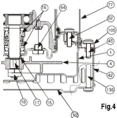
Checking and changing the sealing oil
To perform this operation you must unscrew the six screws of the flange (45) so as to be able to remove the flange (105) and the outer jacket (77). Unscrew the three screws of the filter cover (136) and remove the cover (92) and the filter (42). Unscrew the four screws of the pump body (52) and remove the pump body (1). Using a suitable wrench, unscrew the nut (18) that blocks the impeller, holding the impeller (4) still with your hand. Remove the impeller (4), if necessary with the aid of levers. Recover the tab (17) and the sand protection ring (15), unscrew and remove the cap (64). Tilt the pump so as to drain the oil out of the hole of the cap (64) and pour it into a container. Analyse the oil: if you find any particles of water or abrasive materials (for example, sand) it is advisable to check the condition of the mechanical seal (16) and to have it changed if necessary (at a specialized centre). In this case change the oil too, with about 6 oz / 170 gr of oil type MARCOL 152 ESSO.
Top up the oil level inside the sealing oil chamber using a special funnel inserted in the hole in the cap (64). Screw the drainage cap (64) back on and perform the disassembly operations in inverse order to reassemble the pump after having spread a suitable amount of teflon grease in the seat of the sand guard (15).
Attention! During assembly, fit all the O-rings correctly, without damaging them.
OLD OIL MUST BE DISPOSED OF AS REQUIRED BY THE REGULATIONS IN FORCE.
- TROUBLESHOOTING
| FAULT | CHECK (possible cause) | REMEDY |
| 1. The motor does not start and makes no noise. | A. Check that the motor is live.B. Check the protection fuses.C. The float switch does not allow starting. | B. If they are burnt-out, change them.C. -Ensure that the float moves freely.-Ensure that the float is efficient (contact the supplier). |
| 2. The pump does not deliver. | A. The intake grid or the pipes are blocked.B. The impeller is worn or blocked.C. The check valve, if installed on the delivery pipe, is blocked in closed position.D. The level of the liquid is too low. When starting, the level of the liquid must be higher than that of the strainer.E. The required head is higher than the pump characteristics. | A. Remove the blockage.B. Change the impeller or remove the blockage.C. Check that the valve is operating correctly and replace it if necessary.D. Adjust the length of the float switch cable (SEE THE PARAGRAPH ON "ADJUSTING THE FLOAT SWITCH"). |
| 3. The pump does not stop. | A. The switch is not disactivated by the float. | A. -Ensure that the float moves freely.B. -Check float efficiency (the contacts could be damaged - contact the supplier). |
| 4. The flow is insufficient. | A. Ensure that the intake grid is not partly blocked.B. Ensure that the impeller or the delivery pipe are not partly blocked or encrusted.C. Ensure that the impeller is not worn.D. Ensure that the check valve (if fitted) is not partly clogged.E. On three-phase motors, check that the direction of rotation is correct (See the paragraph on "CHECKING THE DIRECTION OF ROTATION"). | A. Remove any blockage.B. Remove any blockage.C. Change the impeller.D. Carefully clean the check valve.E. Invert the connection of two supply wires. |
| 5. The thermal overload protection stops the pump. | A. Check that the liquid to be pumped is not too dense as this could cause overheating of the motor.B. Check that the water temperature is not too high.C. The pump is partly blocked by impurities.D. The pump is mechanically blocked. | C. Carefully clean the pump.D. Check whether there is rubbing between the moving and fixed parts; check the wear of the bearings (contact the supplier). |
DAB PUMPS LTD.
6 Gilbert Court
Newcomen Way
Severalls Business Park
Colchester
Essex
C04 9WN - UK
salesuk@dwtgroup.com
Tel. +44 0333 777 5010
DAB PUMPS BV
'tHofveld 6 C1
info.belgium@dwtgroup.com
Tel. +32 2 4668353
DAB PUMPS INC.
3226 Benchmark Drive
Ladson, SC 29456 - USA
info.usa@dwtgroup.com
Tel. 1-843-797-5002
Fax 1-843-797-3366
000 DAB PUMPS
Novgorodskaya str. 1, block G
office 308, 127247, Moscow - Russia
info.russia@dwtgroup.com
Tel. +7 495 122 0035
Fax +7 495 122 0036
DAB PUMPS POLAND SP. z.o.o.
No.40 Kaituo Road, Qingdao Economic &
Technological Development Zone
Qingdao City, Shandong Province - China
PC: 266500
sales.cn@dwtgroup.com
Tel. +86 400 186 8280
Fax +86 53286812210
DAB PUMPS IBERICA S.L.
Calle Verano 18-20-22
28850 - Torrejón de Ardoz - Madrid
Spain
Info.spain@dwtgroup.com
Tel. +34 91 6569545
Fax: + 34 91 6569676
DAB PUMPS B.V.
Twenty One industrial Estate,
16 Purlin Street, Unit B, Warehouse 4
Olifantsfontein - 1666 - South Africa
info.sa@dwtgroup.com
Tel. +27 12 361 3997
info.germany@dwtgroup.com
Tel. +49 2151 82136-0
Fax +49 2151 82136-36
DAB PUMPS HUNGARY KFT.
H-8800
Nagykanizsa, Buda Ernő u.5
Hungary
Tel. +36 93501700
426 South Gippsland Hwy,
Dandenong South VIC 3175 – Australia
info.oceania@dwtgroup.com
Tel. +61 1300 373 677

WATER•TECHNOLOGY
DAB PUMPS S.p.A.
Via M. Polo, 14 - 35035 Mestrino (PD) - Italy
Tel. +39 049 5125000 - Fax +39 049 5125950
www.dabpumps.com


- INSTRUCTIONS DE MISE EN SERVICE ET D'ENTRETIEN (FR) INSTRUCTIONS FOR INSTALLATION AND MAINTENANCE (EN)
- CONTENTS
- PUMPED FLUIDS
- TECHNICAL DATA AND LIMITS ON USE
- WARNINGS
- INSTALLAZIONE
- ELECTRIC CONNECTION
- Caution: always follow the safety regulations!
- CHECKING THE DIRECTION OF ROTATION (for three-phase motors)
- The correct direction of rotation will be the one in which the flow rate and electric absorption are LOWER!
- STARTING UP
- Adjusting the float switch
- PRECAUTIONS
- Connect pumps that are delivered without cable and/or plugs to an external mains switch with a minimum contact gap of 0.12" / 3 mm in all poles.
- MAINTENANCE AND CLEANING
- Checking and changing the sealing oil
- DAB PUMPS LTD.
- DAB PUMPS BV
- DAB PUMPS INC.
- DAB PUMPS
- DAB PUMPS POLAND SP. z.o.o.
- DAB PUMPS IBERICA S.L.
- DAB PUMPS B.V.
- DAB PUMPS HUNGARY KFT.
- DAB PUMPS S.p.A.
Brand : DAB
Model : DRENAG 1000-1200
Category : Water pump