
Hydrocontrol - Electric pump AL-KO - Free user manual and instructions
Find the device manual for free Hydrocontrol AL-KO in PDF.

User questions about Hydrocontrol AL-KO
0 question about this device. Answer the ones you know or ask your own.
Ask a new question about this device
Download the instructions for your Electric pump in PDF format for free! Find your manual Hydrocontrol - AL-KO and take your electronic device back in hand. On this page are published all the documents necessary for the use of your device. Hydrocontrol by AL-KO.
USER MANUAL Hydrocontrol AL-KO
natural_image
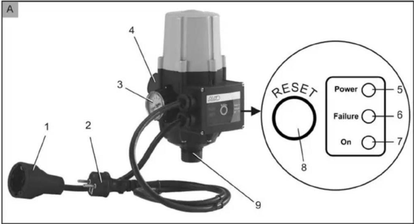
Industrial pressure regulator device with attached plug and cable (no visible text or symbols)


Inhaltsverzeichnis
Deutsch 4
English....9
Nederlands 14
Français....19
Español 25
Portuguese 31
Italiano 36
Slovenščina 42
Hrvatski....47
Polski....52
Česky 58
Slovenská 63
Magyar 68
Dansk 73
Svensk....78
Suomi 83
Русский 88
Україна....94
Türkçe 100
Român 105
© 2023
AL-KO KOBER GROUP Kötz, Germany
This documentation or excerpts therefrom may not be reproduced or disclosed to third parties without the express permission of the AL-KO KOBER GROUP.

1 About these operating instructions...... 9
1.1 Legends and signal words...... 9
2 Product description ...... 9
2.1 Scope of supply 9
2.2 Product overview 9
2.3 Function.... 10
2.4 Functions of the pressure switch ..... 10
2.5 Intended use.... 10
2.6 Possible misuse.... 10
3 Safety instructions.... 10
3.1 General safety warnings.... 10
3.2 Electrical safety.... 11
4 Installation.... 11
5 Start-up 11
6 Operation 11
6.1 Manual restart.... 12
6.2 Switching the pump off 12
6.3 Operating status displays 12
7 Maintenance and care.... 12
8 Help in case of malfunction.... 12
9 Storage.... 13
10 Disposal 13
11 After-Sales/Service 13
12 Information on the Declaration of Confor- mity.... 13
13 Warranty.... 13
1 ABOUT THESE OPERATING INSTRUCTIONS
The German version is the original operating instructions. All additional language versions are translations of the original operating instructions.
It is essential to read through these operating instructions carefully before start-up. This is essential for safe working and trouble-free handling.
■ Always safeguard these operating instructions so that they can be consulted if you need any information about the appliance.
■ Only pass on the appliance to other persons together with these operating instructions.
■ Comply with the safety and warning information in these operating instructions.
1.1 Legends and signal words
⚠️ DANGER! Denotes an imminently dangerous situation which will result in fatal or serious injury if not avoided.
WARNING! Denotes a potentially dangerous situation which can result in fatal or serious injury if not avoided.
CAUTION! Denotes a potentially dangerous situation which can result in minor or moderate injury if not avoided.
IMPORTANT! Denotes a situation which can result in material damage if not avoided.
NOTE Special instructions for ease of understanding and handling.
2 PRODUCT DESCRIPTION
2.1 Scope of supply
The pressure switch is supplied complete with two connecting cables.
The installation materials for connection to a pump are not included in the scope of supply.
2.2 Product overview
| No. Component |
| 1 Connecting cable to pump |
| 2 Connecting cable with mains plug |
| 3 Pressure gauge |
| 4 Pressure line connection (1" male thread) |
| 5 "Power" LED |
| 6 "Failure" LED |
| 7 "ON" LED |
| 8 "Reset" button |
No. Component
9 Connection to pump (1" male thread)
2.3 Function
The Hydrocontrol is an electronic pressure switch with integrated dry running protection and backflow stopper. It serves to convert a surface pump into a domestic water pump.
2.4 Functions of the pressure switch
Automatic operation of the pump
When a shut-off device in the pressure line is opened, the pump is automatically switched on by the pressure switch. When the shut-off device is closed, the pressure switch switches off the pump again once the maximum pump pressure is reached.
Protection of the pump against dry running
The pressure switch is equipped with a safety device that switches off the pump in the event of a lack of water.
The pump is switched off after approx. 45 s, signalled by the lighting up of the "Failure" LED.
Constant delivery rate and pressure
The pressure switch ensures a constant delivery rate with constant pressure.
Functioning range of the pressure switch
ON pressure: approx. 1.8 bar
OFF pressure max.: 8.0 bar (or maximum pressure of pump)
2.5 Intended use
The appliance is intended for private use in the house and garden. It may only be operated within the framework of the operating limits indicated in the technical data.
The appliance is suitable for:
■ Conversion of a surface pump or submersible pressure pump into a pump with automatic switching (domestic water pump).
The appliance is suitable only for conveying the following fluids:
Clean water
Rainwater
■ Chlorinated water (swimming pool water).
Any use not in accordance with this designated use shall be regarded as misuse.
2.6 Possible misuse
The pump must not be operated continuously. It is not suitable for conveying:
- Drinking water
Salt water
Foodstuffs
Waste water
■ aggressive media, chemicals
■ corrosive, flammable, explosive or fuming fluids
■ fluids that are hotter than 35 °C
■ water containing sand and abrasive fluids.
3 SAFETY INSTRUCTIONS
⚠️ DANGER! Danger from contact with live parts! A defect in the pump or the extension cable can result in serious injury!
■ Disconnect the connector plug from the mains immediately.
■ Connect the device via an earth leakage circuit breaker with a rated leakage current of < 30 mA.
WARNING! Risk of injury. Defective and disabled safety and protective devices can result in serious injury.
■ Have any defective safety and protective devices repaired.
■ Never disable safety and protective devices.
CAUTION! Danger of injury from hot wa-
ter After extended use against the closed pressure side (> 10 min.), the water in the pump can become very hot and may escape uncontrolled!
■ Disconnect the pump from the mains supply and allow the pump and water to cool down.
- Check the water level on the suction side.
■ Check the leak-tightness of the lines.
- Check the installation of the suction and pressure lines.
- Put the pump into operation again only after all the faults have been remedied!
3.1 General safety warnings
This appliance can be used by children of 8 years and older and by persons with reduced physical, sensory or mental capabilities, or those lacking experience and knowledge, if they are supervised or have been instructed with regard to the safe use of the appliance
and the ensuing risks. Children must not be allowed to play with the appliance. Cleaning and maintenance must not be carried out by children without supervision.
■ People with very strong and complex restrictions may have needs that exceed the instructions described here.
■ Never lift, transport or affix the pump by the mains cable. Do not pull the mains cable in order to pull the mains plug out of the socket.
■ Unauthorised modifications or conversions to the pump are prohibited. Repairs may only be carried out by our customer service.
■ Disconnect the mains plug before working on the device. Protect the mains plug against moisture.
■ Only use the pump and extension cable if they are in flawless technical condition. Damaged appliances must not be operated.
- Maintain a safe distance to persons or animals or switch off the pump if animals approach.
3.2 Electrical safety
■ The pump may not be operated while people are in the pool or pond.
The mains voltage at your location must comply with the information regarding mains voltage in the Technical Data. Do not use any other supply voltage.
The appliance must only be operated on electrical equipment in accordance with DIN/VDE 0100, parts 737, 738 and 702. For fuse protection, a circuit breaker of 10 A and an earth leakage circuit breaker with a rated leakage current of 10/30 mA must be installed.
Use only 3 x 1.5 mm ^2 extension leads of quality H07RN-F to DIN 57282/57245 with splash-proof plug connector. Cable drums must be completely unwound.
The power consumption of the connected pump must not exceed 10 A, and its operating pressure must not be less than 1.8 bar or more than 8 bar.
■ Always switch off the pump operated with the pressure switch and pull the mains plug of the connecting lead out of the plug socket before starting maintenance, service and repair work or in the event of faults. Protect the mains plug from moisture.
4 INSTALLATION
IMPORTANT! Danger of damage to the pump! If a pre-filter is not installed, solids can enter the pump and cause damage.
■ Install a pre-filter in the suction line for safe operation of the pressure switch.
NOTE The pressure switch can be installed at any point in the pressure line.
The pressure switch must always be installed vertically. If direct installation at the pump outlet is not possible for space reasons, a suitable connector must be used.
- Install the pressure switch (1" male thread) to the pressure line connection at the pump outlet.
5 START-UP
NOTE The pump cannot be filled via the pressure switch, as a check valve is installed in front of the pump.
NOTE During commissioning, the pump switches off automatically after approx. 10 s. The "RESET" (8) button must then be pressed until the pump starts to deliver water. If the "RESET" button is released before the pump starts to deliver water, the pump switches off again automatically for safety reasons. Should the priming process take longer than 2 minutes, fill the pump and suction hose again, check the screw fittings for leaks and repeat the process.
-
Fill pump and suction until they overflow.
-
Open a shut-off device (valve, spray nozzle, water cock) in the pressure line.
-
Insert the plug of the mains cable into the power socket. The pumps starts to operate.
-
Close the shut-off device in the pressure line when water flows out of the line without bubbles. The pressure switch switches off the pump automatically after approx. 15 s. The appliance is ready for operation.
6 OPERATION
Commission the appliance as described.
The pressure switch is electronically controlled and operates fully automatically after commissioning.
6.1 Manual restart
- After malfunctions or if no water is pumped during commissioning, the pump has to be started manually.
- Check the suction side of the appliance and the water level.
- Start the pump by pressing the "RESET" (8) button.
- If no water is pumped after several unsuccessful attempts, check the screw fittings for tightness and fill the pump again.
6.2 Switching the pump off
- Remove the mains plug from the plug socket.
6.3 Operating status displays
The operating statuses are signalled by means of indicator lights (LED).
Indicates whether the appliance is connected to the mains power supply.
"Failure" indicator light (6)
Indicates that a malfunction has occurred.
"On" indicator light (7)
Indicates that the pump is in operation.
7 MAINTENANCE AND CARE
DANGER! Danger of electric shock!
There is a risk of electric shock when working on the pump.
■ Disconnect the mains plug before starting any fault remedying work.
■ Faults in the electrical system must be rectified by a qualified electrician.
8 HELP IN CASE OF MALFUNCTION
DANGER! Danger of electric shock!
There is a risk of electric shock when working on the pump.
■ Disconnect the mains plug before starting any fault remedying work.
■ Faults in the electrical system must be rectified by a qualified electrician.
NOTE In the event of other malfunctions, please refer to the operating manual of the connected pump. In the event of faults that you cannot rectify, please contact our Customer Service department.
| Malfunction Possible cause | Remedy | |
| "Power" LED does not light up | No mains power. Check the power supply or have it checked by a qualified electrician. | |
| "On" LED does not light up Fault in the electronics. Contact Customer Service. | ||
| "Power" LED lights up, "On" LED is not lit | Pressure line clogged. Check the pressure line. | |
| Tapping point is higher than 15 m. | Reduce the tapping height. | |
| Lack of water on the suction side. | Check suction-side connections and water level. | |
| Pump impeller is blocked. Clean the pump. | ||
| Thermal protection device of the pump has tripped. | Press "RESET" button (8). | |
| "Power" LED and "On" LED light up | Fault in the electronics. Contact Customer Service. | |
| "Failure" LED lights up Lack of water. Check the pump and suction line and carry out commissioning. | ||
9 STORAGE
NOTE If there is the danger of frost, the system must be completely drained and the pump must be stored in a frost-proof place.
10 DISPOSAL

Electrical and electronic appliances do not belong in household waste, but should be collected and disposed of separately.
Packaging, equipment and accessories are made from recyclable materials, and must be disposed of accordingly.
11 AFTER-SALES/SERVICE
In the event of questions of warranty, repair or spare parts, please contact your nearest AL-
KO Service Centre. These can be found on the Internet at:
www.alko-garden.com/service-contacts
Further information on spare parts can be found at:
www.alko-garden.com/spareparts
12 INFORMATION ON THE DECLARATION OF CONFORMITY
We hereby declare, as the exclusively responsible party, that this product in its marketed form meets the requirements of the harmonised EU Directives, EU safety standards and the product-specific standards. The Declaration of Conformity forms part of the operating instructions and is included with the machine.
13 WARRANTY
We will remedy any material or manufacturing defects discovered in the device during the statutory period of limitation for claims for defects by repair or replacement at our discretion. The period of limitation is determined in each case by the law of the country in which the device was purchased.
Our warranty promise applies only if:
■ These operating instructions are observed
■ The device is handled correctly
■ Original spare parts have been used
The warranty becomes void in the case of:
■ Unauthorised repair attempts
■ Unauthorised technical modifications
■ Use for other than the intended purpose
The warranty does not include:
■ Paint damage attributable to normal wear
■ Wear parts that are marked with a box xxxxxx (x) on the spare parts card
The warranty period commences with the purchase by the first end user. The date on the proof of purchase is decisive. In the event of a warranty claim, please contact your dealer or the nearest authorised customer service centre with this declaration and the original proof of purchase. This declaration does not affect the purchaser's statutory claims for defects against the vendor.
VERTALING VAN DE ORIGINELE GEBRUIKERSHANDLEIDING
Inhoudsopgave
11 Klantenservice/service centre 18
2 PRODUCTBESCHRIJVING
Luz-piloto "Failure" (6)
11 SERVISNA SLUŽBA/SERVIS
11 Kundeservice/service.... 77
Imported by: AL-KO Gardentech UK Ltd, Murray way, Wincanton, Somerset, BA9 9RS / UK | +44 (0) 1963 828055
shop.uk@al-ko.com | www.alko-garden.uk
AL-KO Service: www.al-ko.com/service-contacts