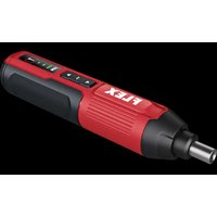
SD 5-300 4.0 - Drill Flex - Free user manual and instructions
Find the device manual for free SD 5-300 4.0 Flex in PDF.


User questions about SD 5-300 4.0 Flex
0 question about this device. Answer the ones you know or ask your own.
Ask a new question about this device
Download the instructions for your Drill in PDF format for free! Find your manual SD 5-300 4.0 - Flex and take your electronic device back in hand. On this page are published all the documents necessary for the use of your device. SD 5-300 4.0 by Flex.
USER MANUAL SD 5-300 4.0 Flex
text_image
Diagram showing a drill bit connected to a device via cable, with close-up details of the component and wiring.C
text_image
FLEX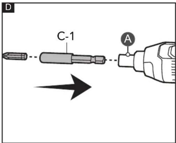
text_image
D C-1 A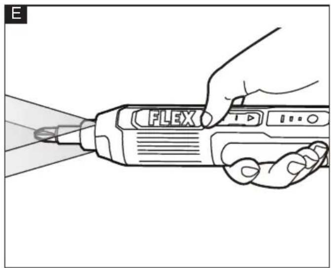
natural_image
Line drawing of a hand using a Flex power tool to shoot a light bulb (no text or symbols on the tool itself)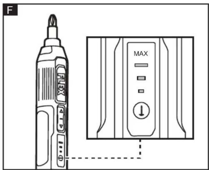
text_image
F FLEX MAX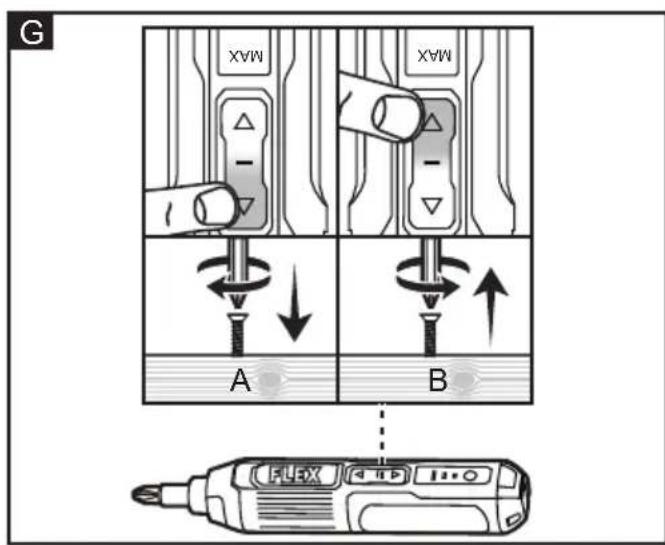
text_image
G MAX - MAX A B FLEX 100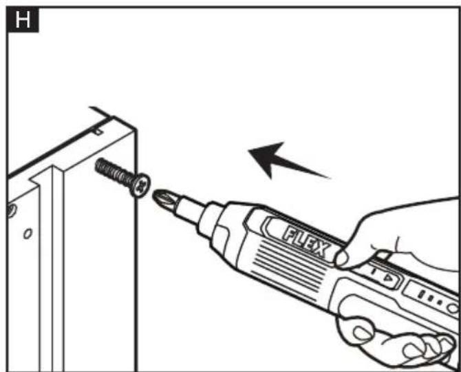
text_image
H FLEXSymbols used in this manual

WARNING!
Denotes impending danger. Non-observance of this warning may result in death or extremely severe injuries.

CAUTION!
Denotes a possibly dangerous situation. Non-observance of this warning may result in slight injury or damage to property.

NOTE
Denotes application tips and important information.
Symbols on the power tool
V
Volts
/min Rotation rate

To reduce the risk of injury, read the operating instructions!

Disposal information for the old machine (see page 13)!

Protect the battery against heat, including prolonged sunshine, and fire. explosion hazard.
Do not throw the battery into a fire. explosion hazard!
For your safety

WARNING!
Before using the power tool, please read the follow:
– these operating instructions,
- the "General safety instructions" on the handling of power tools in the enclosed booklet (leaflet-no.: 315.915),
- the currently valid site rules and the regulations for the prevention of accidents.
This power tool is state of the art and has been constructed in accordance with the acknowledged safety regulations.
Nevertheless, when in use, the power tool may be a danger to life and limb of the user or a third party, or the power tool or other property may be damaged.
The cordless screwdriver may be used only –asintended,
- in perfect working order. Faults which impair safety must be repaired immediately.
Intended use
The cordless screwdriver is intended
- The power tool is intended for screwing in and loosening screws.
Safety instructions for screwdriver

WARNING!
Read all safety warnings, instructions, illustrations and specifications provided with this power tool. Failure to follow all instructions listed below may result in electric shock, fire and/or serious injury. Save all warnings and instructions for future reference.
- Hold the power tool by insulated gripping surfaces, when performing an operation where the fastener may contact hidden wiring. Fasteners contacting a "live" wire may make exposed metal parts of the power tool "live" and could give the operator an electric shock.
■ Use suitable detectors to determine if there are hidden supply lines or contact the local utility company for assistance. Contact with electric cables can cause fire and electric shock. Damaging gas lines can lead to explosion. Breaking water pipes causes property damage.
■ Before any work on the power tool (e.g. maintenance, tool change, etc.) as well as during transport and storage, set the rotational direction switch to the middle position. There is risk of injury from unintentionally pressing the on/off switch.
■ Hold the power tool securely. When tightening and loosening screws be prepared for temporarily high torque reactions.
■ Secure the workpiece. A workpiece clamped with clamping devices or in a vice is held more secure than by hand.
■ Always wait until the power tool has come to a complete stop before placing it down. The application tool can jam and cause you to lose control of the power tool.
Safety instructions for Li-ion batteries

WARNING!
Read all safety warnings and all instructions.
Failure to follow the warnings and instructions may result in electric shock, fire and/or serious injuries. Save all warnings and instructions for future reference.
■ Do not open the battery. There is a risk of a short-circuit.
■ Protect the battery from heat, e.g. from continuous exposure to sunlight, fire, water and humidity. There is a risk of explosion.
■ If the battery is damaged or used improperly, fumes may be emitted. Provide fresh air and consult a doctor if you feel unwell. The fumes may irritate the respiratory tract.
■ Under abusive conditions, liquid may be ejected from the battery; avoid contact. If contact accidentally occurs, flush with water. If liquid contacts eyes, additionally seek medical help. Liquid ejected from the battery may cause irritation or burns.
■ The battery voltage must match the battery charging voltage of the battery charger. Otherwise there is a risk of fire and explosion.
■ Integrated batteries may only be removed for disposal by qualified personnel. Opening the housing shell can destroy the power tool.
Noise and vibration
The noise and vibration values have been determined in accordance with EN 62841.
The A evaluated noise level of the power tool is typically:
– Sound pressure level L_pA : 50.97 dB(A);
– Sound power level L_WA : 61.97 dB(A);
- Uncertainty: K = 3 dB.
Total vibration value:
- Emission value a_h : <2.5 m/s
- Uncertainty: K = 1.5 m/s

CAUTION!
The indicated measurements refer to new power tools. Daily use causes the noise and vibration values to change.

NOTE
The vibration emission level given in this information sheet has been measured in accordance with a measurement method standardised in EN 62841 and may be used to compare one tool with another.
It may be used for a preliminary assessment of exposure. The specified vibration emission level represents the main applications of the tool.
However, if the tool is used for different applications, with different cutting accessories or poorly maintained, the vibration emission level may differ.
This may significantly increase the exposure level over the total working period.
To make an accurate estimation of the vibration exposure level, it is also necessary to take into account the times when the tool is switched off or running but not actually in use.
This may significantly decrease the exposure level over the total working period.
Identify additional safety measures to protect the operator from the effects of vibration such as: maintain the tool and the cutting accessories, keep the hands warm, organisation of work patterns.

CAUTION!
Wear ear defenders at a sound pressure above 85 dB(A).
Technical data
| Tool SD 5-300 4.0 | ||
| Type Screwdriver | ||
| Rated voltage Vdc 4 | ||
| Battery capacity Ah 2 | ||
| Rated No-load Speed | RPM 300 | |
| Maximum Torque | Nm | 5 |
| Weight | kg | 0.28 |
| Working Temperature | 10-35°C | |
| Storage Temperature | 0-40°C | |
| Charging Temperature | 5-40°C | |
Overview (see figure A)
The numbering of the product features refers to the illustration of the machine on the graphics page.
1 Magnetic bit holder
2 LED worklight
3 Forward/reverse switch
4 Battery/torque indicator
5 Battery/torque button
6 Charging port with cover
7 Hand strap hole
8 Handle
9 USB charging cable
Operating instructions
Before switching on the power tool
Unpack the cordless screwdriver and check that here are no missing or damaged parts.

NOTE
The batteries are not fully charged on delivery. Prior to initial operation, charge the batteries fully.
Charging the battery (see figure B)

WARNING!
Risk of injury! Do not charge the tool for more than 24 hours.
The optimal charge is achieved after 3 hours. To check the amount of battery left in the tool, press and hold the battery/torque button (5). The battery/torque indicator (4) lights up accordingly.
| Battery/torque indicator | Battery capacity |
| 1 LED lights up <40% | |
| 2 LEDs light up 40%-70% | |
| 3 LEDs light up >70% |
■ Connect the USB-A side of USB charging cable (9) to a suitable 5 V USB battery charger adaptor (not included).
■ Lift the rubber cover and connect the other side of the USB charging cable to the
charging port (6) of the tool.
■ Connect the USB battery charger adaptor to a suitable socket outlet. The battery/torque indicators (4) flash green while the tool is charging.
| Battery/torque indicator | Battery capacity |
| 3 LEDs circularly flash | <40% |
| 2 LEDs circularly flash | 40%-70% |
| 1 LED flashes >70% |
■ The battery/torque indicators (4) stay on green for 100 seconds then goes off when the tool is fully charged.
■ After charging, unplug the tool.
Install and remove bit
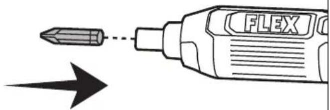
■ Insert a bit into the magnetic bit holder (1). The magnetized holder holds the bit in place (see figure C).
■ To installing a bit with hex shank bit extension C-1, insert it into the magnetic bit holder (1). The magnetized holder holds the hex shank bit extension in place (see figure D).
■ To remove the bit, pull the bit out of the magnetic bit holder.

WARNING!
The bit may be very hot after use. Allow the bit to cool down or wear gloves when removing a bit.
LED worklight
This tool is equipped with two LED worklights (2) that illuminate when the forward/reverse switch (3) is pressed.
To switch on the LED worklights (2), press on the forward/reverse switch (3). The LED worklights (2) switch off automatically after approx. 10 seconds the forward/reverse switch (3) is released (see figure E).
Selecting a torque
Press the battery/torque button (5) to switch between torque settings (see figure F).
The battery/torque indicator (4) lights up accordingly:
| Battery/torque indicator | Torque |
| 1 LED on Lowest torque | |
| 2 LEDs on Medium torque | |
| 3 LEDs on Highest torque |
Selecting the rotation direction (see figure G)
For forward/tighten direction: Press the front part of the forward/reverse switch (3).
For reverse/loosen direction: Press the rear part of the forward/reverse switch (3).
Before use
■ Wear personal protective equipment (PPE). Depending on the application, use face shield, safety goggles or safety glasses. As appropriate, wear dust mask, hearing protectors and gloves.
■ Check the tool and its accessories for damage. Do not use the tool if it is damaged or worn out.
- Check for loose screws, misalignment or binding of moving parts, or any other condition that may affect the operation. If abnormal vibration or noise occurs, switch the tool off immediately and have the problem corrected before further use.
■ Charge the tool if needed. Do not use the tool if it is bulging or hot.
■ Always firmly hold the tool by its handle. Keep the tool clean.
■ Switch the tool off immediately if bystanders are interrupting the work. Never lay the tool down until the bit has come to a complete stop. The spinning bit may grab the surface and pull the tool out of your control.
■ Do not work continuously for extensive amounts of time with the tool. Take breaks in between work to ensure full concentration while using the tool.
Driving screw (see figure H)
■ Select and install a suitable bit.
■ Pressing on the desired direction of the forward/reverse switch.
NOTE
Always hold the tool aligned to the fastener. Holding it at an angle may cause slipping or jamming of the fastener.
Maintenance and care
Cleaning
■ Clean the power tool regularly. Frequency of cleaning is dependent on the material and duration of use.
Spare parts and accessories
For other accessories, in particular tools and polishing aids, see the manufacturer's catalogues.
Exploded drawings and spare-part lists can be found on our homepage:
www.flex-tools.com
Disposal information
WARNING!
Render redundant power tools unusable:
- mains operated power tool by removing the power cord,
- battery operated power tool by removing the battery.

EU countries only
Do not throw electric power tools into the household waste!
In accordance with the European Directive 2012/19/EU on Waste Electrical and Electronic Equipment and transposition into national law used electric power tools must be collected separately and recycled in an environmentally friendly manner.
Raw material recovery instead of waste disposal.
Device, accessories and packaging should be recycled in an environmentally friendly manner. Plastic parts are identified for recycling according to material type.
WARNING!
Do not throw batteries into the household waste, fire or water. Do not open used batteries. EU countries only: In accordance with Directive 2006/66/EC defective or used batteries must be recycled.
NOTE
Please ask your dealer about disposal options!
CE-Declaration of conformity
We declare on our sole responsibility that the product described in "Technical specifications" conforms to the following standards or normative documents: EN 62841 in accordance with the regulations of the directives 2014/30/EU, 2006/42/EC, 2011/65/EU. Responsible for technical documents: FLEX-Elektrowerkzeuge GmbH, R & D Bahnhofstrasse 15, D-71711 Steinheim/Murr
Peter Lameli Klaus Peter Weinper Technical Head Head of Quality Department
Exemption from liability
The manufacturer and his representative are not liable for any damage and lost profit due to interruption in business caused by the product or by an unusable product. The manufacturer and his representative are not liable for any damage which was caused by improper use of the product or by use of the product with products from other manufacturers.
UK CA Declaration of Conformity
We as the manufacturer: FLEX Elektrowerkzeuge GmbH, Business address: Bahnhofstr. 15, 71711 Steinheim, Germany declare under our sole responsibility, that the product(s) described under „Technical specifications“ fulfills all the relevant provisions of The Supply of Machinery (Safety) Regulations S.I. 2008/1597 and also fulfills all the relevant provisions of the following UK Regulations:
Electromagnetic Compatibility Regulations S.I. 2016/1091, The Restriction of the Use of Certain Hazardous Substances in Electrical and Electronic Equipment Regulations S.I. 2012/3032 and are manufactured in accordance with the following designated Standards: BS EN 62841-1, BS EN 62841-2-2
Place of declaration: Steinheim, Germany. Responsible person: Peter Lameli, Technical Director - FLEX-Elektrowerkzeuge GmbH
Contact details for Great Britain: FLEX Power Tools Limited, Unit 8 Anglo Office Park, Lincoln Road, HP 12, 3RH Buckinghamshire, United Kingdom.
text_image
i.v. P### 2014-2Peter Lameli Klaus Peter Weinper Technical Head Head of Quality Department
01.11.2022
- Incertitude: K = 3 dB.
Peter Lameli Klaus Peter Weinper Technical Head Head of Quality
Department (QD)
- Negotovost: K = 3 dB.
Skupna vrednost vibracij:
- Vrednost emisij a_h : <2,5 m/s
- Negotovost: K = 1,5 m/s

POZOR!
Technical Head Head of Quality
Department (QD)
Peter Lameli Klaus Peter Weinper Technical Head Head of Quality Department
Technical Head Head of Quality
Department (QD)
Peter Lameli Klaus Peter Weinper Technical Head Head of Quality
Department (QD)
Technical Head Head of Quality
Department (QD)
Technical Head Head of Quality Department (QD)