
59G717 - Milling machine Graphite - Free user manual and instructions
Find the device manual for free 59G717 Graphite in PDF.

User questions about 59G717 Graphite
0 question about this device. Answer the ones you know or ask your own.
Ask a new question about this device
Download the instructions for your Milling machine in PDF format for free! Find your manual 59G717 - Graphite and take your electronic device back in hand. On this page are published all the documents necessary for the use of your device. 59G717 by Graphite.
USER MANUAL 59G717 Graphite
natural_image
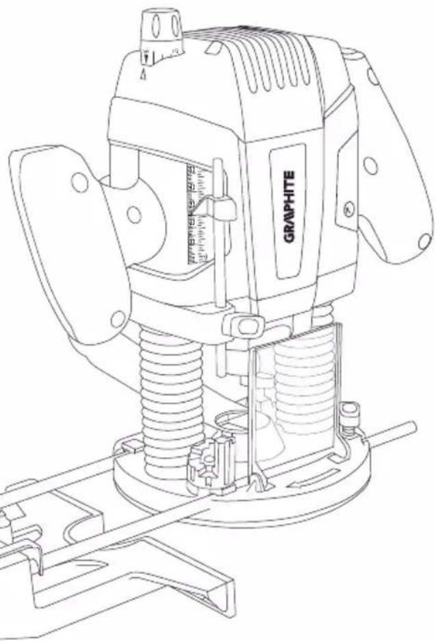
Technical line drawing of a graphite cutting machine (no text or symbols present)59G717

PL INSTRUKCJA OBSŁUGI 6
GB INSTRUCTION MANUAL 12
DE BETRIEBSANLEITUNG....15
RU РУКОВОДСТВО ПО ЭКСПЛУАТАЦИИ ..... 20
UA ІНСТРУКЦІЯ З ЕКСПЛУАТАЦІЇ ..... 25
HU HASZNÁLATI UTASÍTÁS. 29
RO INSTRUCTIUNI DE DESERVIRE .... 33
© INSTRUKCE K OBSLUZE....37
SK NÁVOD NA OBSLUHU 41
SL NAVODILA ZA UPORABO 45
LT APTARNAVIMO INSTRUKCIJA. 49
LV LIETOŠANAS INSTRUKCIJA 53
EE KASUTUSJUHEND 57
ВО ИНСТРУКЦИЯ ЗА ОБСЛУЖВАНЕ ..... 61
HR UPUTE ZA UPOTREBU....65
SR UPUTSTVO ZA UPOTREBU 69
GR OΔΗΓΙΕΣ ΧΡΗΣΗΣ 73
ES INSTRUCCIONES DE USO....78
IT MANUALE PER L'USO 82
NL GEBRUIKSAANWIJZING 87
FR MANUEL D'INSTRUCTION ..... 91
natural_image
Technical line drawing of a mechanical assembly with no visible text or symbols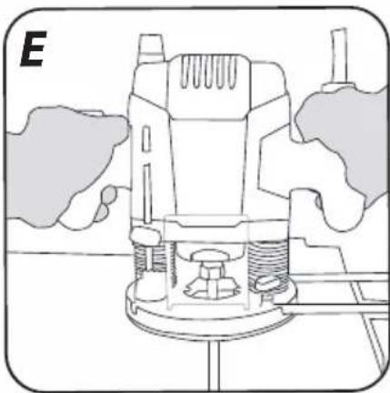
natural_image
Technical line drawing of a mechanical assembly with no visible text or symbols
natural_image
Illustration of a hand operating a mechanical device with a tool, no text or symbols present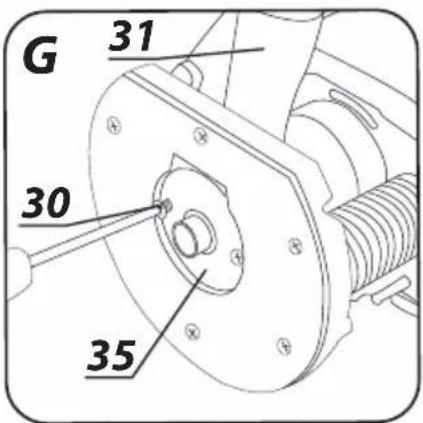

INSTRUKCJA ORYGINALNA (OBSŁUGI)
FREZARKA GÓRNOWRZECIONOWA 59G717
UWAGA: PRZED PRZYSTĄPIENIEM DO UŻYTKOWANIA ELEKTRONARZĘDZIA NAŁEŻY UWAŻNIE PRZECZYTAĆ NINIEJSZĄ INSTRUKCJĘ I ZACHOWAĆ JĄ DO DALSZEGO WYKORZYSTANIA.
SZCZEGÓŁOWE PRZEPISY BEZPIECZEŃSTWA
GTX SERVICE
C ∈
/EC Declaration of Conformity/
/The above listed product is in conformity with the following UE Directives:/
/and fulfils requirements of the following Standards:/
/Name and address of the person who established in the Community and authorized to compile the technical file:/
/GRUPA TOPEX Quality Agent/
CAUTION: BEFORE USING THE POWER TOOL READ THIS MANUAL CAREFULLY AND KEEP IT FOR FUTURE REFERENCE.
DETAILED SAFETY REGULATIONS
- The cutter bit can hit the tool's power cord, therefore hold the power tool only by insulated handle areas. Contact with power supply line may transfer voltage to metal parts of the device and cause electric shock.
- Fix processed material to stable surface and secure with clamps or with any other sufficient means to eliminate shifting. When you hold processed piece in hand or press against your body, the piece is unstable, which may cause loss of control.
- Cutter bits must match exactly to holder of the power tool. Mismatch of the working tool and the power tool holder causes irregular rotation, strong vibrations and may cause loss of control over the power tool.
- Rotary speed of working tools must not be lower than maximum rotary speed specified for the power tool. Equipment subjected to greater rotary speed may get damaged.
- Hold the plunge router by both handles during operation, keep stable body position. Power tool is safer when held with two hands.
- Do not touch rotating cutter bit or put hands in area of the bit operation. Keep your second hand on the additional handle. Guiding the device with both hands reduces risk of cutting hands with the working tool.
- Wear personal protection equipment. Depending on type of work, wear protective mask, goggles, protective glasses and hearing protectors. Protect eyes from particles produced at work and floating in the air. Anti-dust mask provides protection of respiratory tract and must filter out dust produced at work. Prolonged exposure to noise may lead to hearing loss.
- Dust of certain wood types may be dangerous to health. Direct physical contact with dusts may cause allergic reaction and/or respiratory system diseases of operator or bystanders. Dusts of oak and beech are considered carcinogenic, especially in connection with wood processing substances (wood impregnants). Therefore use of anti-dust mask, dust extraction systems and appropriate ventilation is recommended.
- Clean ventilation holes of the power tool on regular basis. Motor blower sucks dust into casing and large depositions of dust may cause electric hazards. Do not use power tool in proximity of flammable materials. Sparks can cause ignition.
- Do not use damaged or blunt cutter bits. Blunt or damaged cutter bits increase friction, can cause jamming and reduce material processing quality.
- Do not touch the cutter bit immediately after the work has been finished. This element may be hot and may cause burns.
- Start the power tool before the cutter bit gets into contact with the processed piece. Otherwise there is a risk of kick back, because used tool can jam in the processed piece.
- Ensure all locking clamps are tightened.
- Never attach working tools other than recommended by the manufacturer to the power tool.
- When changing the cutter bit, make sure its shank is held by at least 20 mm of its length.
- Prior to cutting ensure that there is enough free space under processed material to prevent contact of the cutter bit and other objects.
- Check surface of the working area. Make sure there are no unwanted objects (nails, screws etc.).
- Do not leave the router unattended when switched on.
- When the power tool is not in use, always keep it disconnected from the power supply and stored in a place beyond reach of children.
- Always disconnect the power tool from power supply prior to commencing any activity related to its adjustment, maintenance or operation.
- When cleaning the power tool do not use any solvent that might damage plastic parts.
CAUTION! This device is designed to operate indoors.
The design is assumed to be safe, protection measures and additional safety systems are used, nevertheless there is always a small risk of injuries at work.
Explanation of used symbols

12

3

4

56

- Read instruction manual, observe warnings and safety conditions therein.
- Protection class 2.
- Use personal protection measures (protective goggles, earmuff protectors, anti-dust mask).
- Disconnect the power cord before starting maintenance or repair.
- Keep the tool away from children.
- Protect against rain.
CONSTRUCTION AND USE
Plunge router is a hand-held power tool with protection class 2. It is driven by a single phase commutator motor installed vertically related to processed surface. Power tools of this type are widely used for cutting in wood and wood-based materials. Range of use covers woodworking, wood flooring, decoration or renovation and construction tasks.

Use the power tool in accordance with the manufacturer's instructions only.
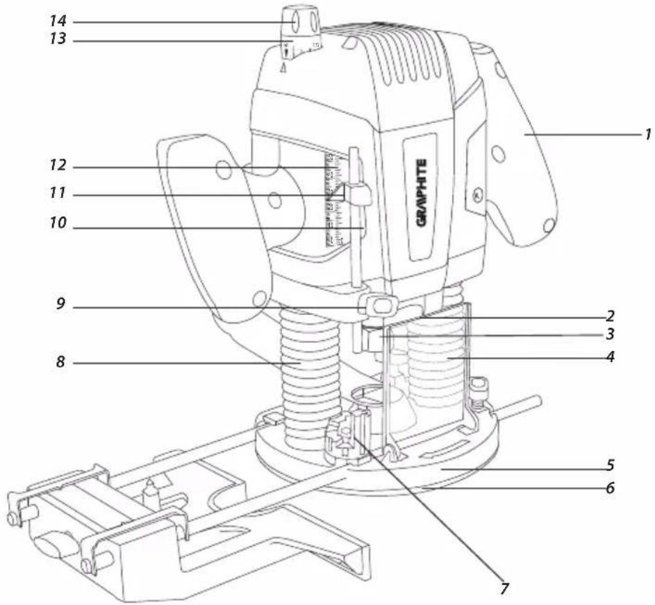
DESCRIPTION OF DRAWING PAGES
Below enumeration refers to the device elements depicted on the drawing pages of this manual.
- Handle
- Spindle lock button
- Spindle
- Spindle guard
- Base
-
Plate
-
Depth gauge stepped bumper
- Anti-dust shield of the body guide
- Depth gauge locking knob
- Depth gauge
- Depth gauge indicator
- Main scale
- Precision scale
- Knob for precise depth adjustment
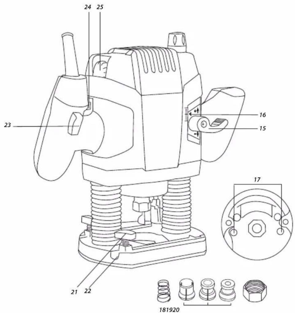
- Plunge guide locking lever
- Indicator for precise depth adjustment
- Illumination
- Spindle spring
- Collet sleeve
- Fixing nut
- Locking knobs for edge guide bars
- Grooves for edge guide bars
- Switch
- Switch lock button
- Wheel for rotational speed control
- Edge guide bar
- Edge guide
- Knob for edge guide position adjustment
- Indicator of edge guide position
- Adapter fixing screw
- Dust extraction adapter
- Reducing connector
- Spike
- Butterfly nut of the spike
- Guide sleeve
- Guide sleeve collar
- Flat key
* Differences may appear between the product and drawing
MEANING OF SYMBOLS

CAUTION

WARNING

ASSEMBLY / SETTINGS

INFORMATION
EQUIPMENT AND ACCESSORIES
- Edge guide - 1 pce
- Spike for cutting along arcs - 1 pce
- Guide sleeve - 1
- Dust extraction adapter with reducer - 1 set
- Adapter fixing screws - 1 set
- Collet sleeve - 3 pcs
- Flat key - 1 pce
Spindle lock button can be used only for working tool installation or removal. It cannot be used as a brake button when the spindle is rotating. Otherwise the power tool may be damaged or the user may be injured.

Do not tighten the spindle nut strongly before inserting a working tool, this can damage the collet sleeve. Make sure that appropriate collet sleeve is used each time the working tool is replaced.

Choice of working tool depends on processed material and type of planned task. Cutter bits made of high speed steel (HSS) are designed for processing soft materials, like plastics or soft wood. Cutter bits made of sintered carbide (HM) are designed for processing harder materials, e.g. hard woods, chipboards, or even aluminium if allowed by the cutter bit manufacturer.

Use only working tools whose allowable rotary speed is higher or equal to maximum power tool speed with no load.
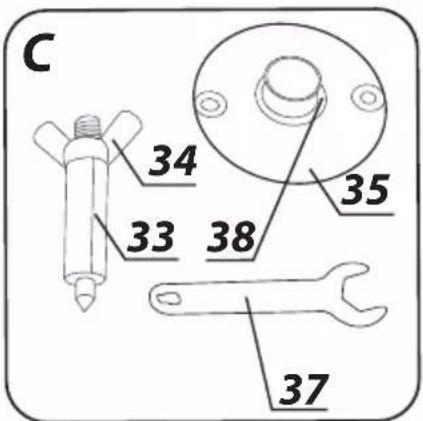
INSTALLATION OF WORK TOOLS

Disconnect the power tool from power supply.
Use protective gloves for installation and removal of working tools.
• Lower the spindle guard (4).
- Press and hold the spindle lock button (2). If necessary, turn the spindle (3) by hand until the lock engages. Depending on the working tool shaft diameter, use appropriate collect sleeve (19). Bear in mind the spring (18) that operates with it. When replacing the collet sleeve, start with putting the spring (18) into the spindle, then collet sleeve (19) of appropriate size. Then lock them in place by installing the fixing nut (20).
- Slide the working tool shank into the spindle to at least 20 mm depth.
- Tighten the fixing nut (20) with the flat key (37) (fig. C).
- Release the spindle lock button (2).
- Set up the spindle guard (4).

Tighten the fixing nut with the flat key only when there is a working tool inside the spindle. Otherwise handle the fixing nut gently and only by hand, to avoid damage to the collet sleeve.
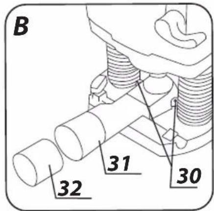
INSTALLATION OF DUST EXTRACTION ADAPTER
You can protect yourself from dust by using anti-dust mask and appropriate device for dust extraction.
Disconnect the power tool from power supply.

Remove working tool before installing dust extraction adapter (31) (fig. B).
- Loosen the plunge guide locking lever (15) to set the router spindle in upper position.
- Place the dust extraction adapter (31) in the base (5) and fix with adapter fixing screws (30) (fig. B), by driving them from below.
- Connect dust extraction hose to the dust extraction adapter (31) either directly or use reducing connector (32), depending on the connector diameter of the hose.
SWITCHING ON / SWITCHING OFF
The mains voltage must match the voltage on the router rating plate.
The router is equipped with the switch lock button that protects against accidental start up.
Switching on
- Press the switch lock button (24).
- Press and hold the switch (23).
Switching off
- Release pressure on the switch button (23).
Illumination
The device is equipped with illumination feature (17) that improves visibility in the workplace. Illumination turns on automatically when the device is turned on.
ADJUSTMENT OF SPINDLE ROTATIONAL SPEED
Wheel for rotational speed control (25) is located on the router body. Select spindle speed depending on your needs (depending on the cutter bit used, hardness of processed material, type of work etc.).


The below table is a user's guideline and shows exemplary settings.
| Material Cutter size | Setting of speed adjustment wheel | |
| Aluminium | 4-15 mm | 1-2 |
| 14-40 mm | 1 | |
| Plastics | 4-15 mm | 2-3 |
| 16-40 mm | 1-2 | |
| Chipboard | 4-10 mm | 3-6 |
| 12-20 mm | 2-4 | |
| 22-40 mm | 1-3 | |
| Soft wood, e.g. pine, spruce | 4-10 mm | 5-6 |
| 12-20 mm | 3-6 | |
| 22-40 mm | 1-3 | |
| Hard wood, e.g. oak, beech | 4-10 mm | 5-6 |
| 12-20 mm | 3-4 | |
| 22-40 mm | 1-2 |

Select setting after performing practical test. It is recommended to do a few initial try cuts on waste material before commencing the planned work with the target material.

When working with low rotational speed for a long time it is recommended to cool down the device. To do that, start the power tool with no load and keep it going at full speed for approximately 1 minute.
ROUTER PLUNGING
- Place the router on even surface.
- Unlock the plunge guide locking lever (15).
- Hold the handles with both hands and press the tool downwards, overcoming the spring resistance.
- Release the pressure, springs will automatically return the router body to default (upper) position.
SETTING THE CUTTING DEPTH

Disconnect the power tool from power supply.
- Place the router on even surface.
- Unlock the plunge guide locking lever (15).
• Overcome the spring resistance and bring down the router body, so the cutter bit touches surface the router is placed on. - Lock the tool in the position with the plunge guide locking lever (15).
- Loosen the depth gauge locking knob (9).
- Pull down the depth gauge (10) so it contacts one of the surfaces of the depth gauge stepped bumper (7).
- When necessary, reset the depth gauge indicator (11) by shifting it on the depth gauge (10).
- Put the depth gauge (10) at the height that corresponds to required cutter bit plunging in processed material. Use the main scale (12) on the router body. Then tighten the depth gauge locking knob (9) to lock the setting.

You can set cutting depth precisely by turning knob for precise depth adjustment (14). A full turn of the knob shifts the router body vertically by 1.5 mm as shown by the precision scale (13) and scaling every 0.1 mm. Range of depth adjustment is +/- 8 mm, which is carried out by lifting or lowering the cutter body in relation to the depth gauge stepped bumper (7). This causes reduction or increase of working tool plunging depth. The shift is visible on the indicator for precise depth adjustment (16).
Perform this action when the router is lowered to the point defined by the depth gauge (10). Before adjustments, additionally loosen the depth gauge locking knob (9). Only then the cutter body will be able to shift freely during adjustments, along with the limiter. Once the adjustments are finished, make sure the depth gauge (10) is in contact with the depth gauge stepped bumper (7), then tighten the depth gauge locking knob (9).


The router features depth gauge stepped bumper (7), that allows to move (plunge) the cutter bit into material to one of eight equally spaced positions (each pitch equals to approximately 3 mm).
ROUTING
Hold the router with both hands during operation!
• Install appropriate cutter bit (see above instructions).
- Put the base (5) on material that you plan to process (the cutter bit must not touch the material at this time).
- Set routing depth.
- Switch on the router and wait until the spindle achieves the preset idle speed.
- Start working, move the router base along the processed material surface in desired direction.
- Move the router in steady, continuous movement, pressing the base to the material surface all the time until you finish routing.
Too fast router advance during operation will result in low quality of cutting and may cause damage of cutter bit or motor. Too slow router advance may also result in low quality of cut due to material overheating. Appropriate speed depends on size of the cutter bit in use, type of processed material and processing depth. It is recommended to make some tries on waste material before commencing the planned work. During edge processing, the processed material should be at the left side from the cutter bit axis (looking in the direction of the router advance). When you use linear guide for linear processing or trimming, ensure that additional accessories are well fixed.
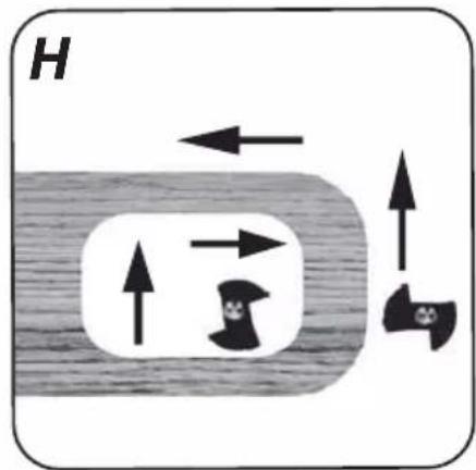
ROUTING DIRECTION
To avoid uneven edges and achieve best results of work, move the router counter-clockwise for outer edges and clockwise for inner edges (fig. H). Better control over the material and the tool itself requires processing in the direction that is opposite to the direction of the working tool.
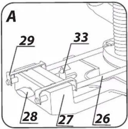
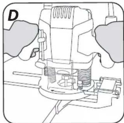
INSTALLATION AND USE OF THE EDGE GUIDE
Edge guide is used for cutting at even distance from an edge of reference. Special design allows for use at processing edges (fig. D) or routing at a constant distance, parallel to an edge (fig. E).
- Loosen the locking knobs for edge guide bars (21) located in the router base (5).
- Slide the edge guide bars (26) (fig. A) into the grooves for edge guide bars (22) and set up required distance.
- Tighten the locking knobs for edge guide bars (21).
- To set up the edge guide (27) precisely, you can use the knob for edge guide position adjustment (28). Change of the edge guide (27) position shows with shifting of the indicator of edge guide position (29) (fig. A).
INSTALLATION OF GUIDE SLEEVE
Guide sleeve allows for precise run of the router along a template edge and precise copying of its shape.
- Undo the adapter fixing screws (30) to remove the dust extraction adapter (31).
- Place the guide sleeve (35) in the router base (5) seating.
- Install the dust extraction adapter (31) and tighten two parts with the adapter fixing screws (30) (fig. G).
Using guide sleeve limits allowable cutter bit size.
Distance from the cutter bit edge and outer edge of the guide sleeve collar (36) (fig. C) defines difference in dimensions of the template and its reproduction after routing with the copying sleeve (35). Change of working diameter of the cutter bit will change this
difference. The copying sleeve (35) can be used with templates of at least 8 mm thickness.
ROUTING ALONG AN ARC

• Install the spike (33) in the edge guide (27) hole (fig. A).
- Remove the edge guide (10) from the router base if installed for edge routing.
- Slide the edge guide (10) in upside down position, with the spike (33) pointing down.
- Set the routing radius and fix the locking knobs for edge guide bars (21).
- Drive the spike (33) into material and then you can start routing along an arc (fig. F).

To define routing radius, measure distance from the centre marker to the outer edge of the cutter bit.
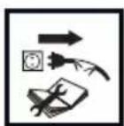
Unplug the power cord from the mains socket before commencing any activities related to installation, adjustment, repair or maintenance.
- Do not use water or any other liquid for cleaning.
- Clean the router with a brush.
- Replace immediately worn out cutter bit.
- Clean ventilation holes of the router regularly to prevent motor overheating.
REPLACEMENT OF CARBON BRUSHES

Immediately replace worn out (shorter than 5 mm), burnt or cracked motor carbon brushes. Always replace both brushes at a time.
Entrust replacement of carbon brushes only to a qualified person. Only original parts should be used.

All defects should be repaired by service workshop authorized by the manufacturer.
TECHNICAL PARAMETERS
RATED PARAMETERS
| Plunge Router 59G717 | |
| Parameter Value | |
| Supply voltage 230V AC | |
| Power supply frequency 50Hz | |
| Rated power 1300W | |
| Range of idle rotational speed 11000 - 28000 | rpm |
| Router body pitch 55 mm | |
| Collet sleeve diameters ∅ 6; 8; 12 mm | |
| Protection class II | |
| Weight | 3,5 |
| Year of production 2019 | |

NOISE LEVEL AND VIBRATION PARAMETERS
Noise and vibration information
Parameters of produced noise level, such as sound pressure level L_pA and sound power level L_WA with measurement uncertainty K are specified below in this manual, in compliance with EN 60745. Vibration values a_h and measurement uncertainty K are determined in accordance with EN 60745 and specified below. Vibration level specified below in this manual was measured in accordance with measurement procedure defined in EN 60745 and can be used to compare power tools. It can also be used for initial assessment of exposure to vibrations.
Specified vibration level is representative for main applications of the power tool. Vibration level may change if the power tool is used for other purposes, with different working tools or will not be maintained properly. The abovementioned factors may lead to higher exposure to vibrations during whole working time.
To precisely define exposure to vibrations, include periods when the power tool is switched off and when it is switched on but not used for working. This way total exposure to vibrations may be significantly lower. Use additional safety measures to protect the user against results of exposure to vibrations, such as: power tool and working tool maintenance, proper hand temperature conditions, good work organisation.
Sound pressure level: L_pA = 90 dB (A) K=3dB (A)
Sound power level: L_WA = 101 dB (A) K=3dB (A)
Vibration acceleration: ah = 12.065 m/s ^2 K = 1.744 m/s ^2
ENVIRONMENTAL PROTECTION

Electrical equipment must not be disposed off with household waste and, instead, should be utilized at appropriate facilities. Information on utilization can be provided by the product vendor or the local authorities. Waste electrical and electronic equipment contains substances that are not neutral to the natural environment. Equipment that is not recycled constitutes a potential hazard to the environment and to human health.
* Right to introduce changes is reserved.
"Grupa Topex Spółka z ograniczoną odpowiedzialnością" Spółka komandytowa with seat in Warsaw at ul. Pograniczna 2/4 (hereinafter Grupa Topex) informs, that all copyrights to this instruction (hereinafter Instruction), including, but not limited to, text, photographies, schemes, drawings and layout of the instruction, belong to Grupa Topex exclusively and are protected by laws accordingly to Copyright and Related Rights Act of 4 February 2004 (ustawa o prawie autorskim i prawach pokrewnych, Dz. U. 2006 No 90 item 631 with later amendments). Copying, processing, publishing, modifications for commercial purposes of the entire Instruction or its parts without written permission of Grupa Topex are strictly forbidden and may cause civil and legal liability.

A KÖRÍVMARÓ FELTÉT ALKALMAZÁSA
BRĪDINĀJUMA ZĪMJU NOZĪME

UZMANĪBU

BRĪDINĀJUMS

MONTĀŽA / REGULĒŠANA

INFORMÃCIJA
APRĪKOJUMS UN PAPILDAKSESUĀRI
POSEBNI PROPISI O SIGURNOSTI
- Električni alat držite samo na izoliranim površinama rukohvata, jer bi glodalo moglo zahvatiti priključni kabel električnog alata. Kontakt sa električnim vodom pod naponom mogao bi staviti pod napon i metalne dijelove uređaja što bi moglo dovesti do strujnog udara.
- Materijal koji namjeravate obrađivati pričvrstite na stabilnoj podlozi i osigurajte od pomicanja pomoću stege ili na neki drugi način. Ako obrađivani element držite samo rukom ili ga pritisnete uz tijelo, on će ostati nestabilan što može dovesti do gubitka kontrole nad alatom.
- Glodala moraju biti prilagođena steznoj glavi korištenog električnog alata. Radni alat koji nije prilagođen električnom alatu vrti se nejednolično, jače vibrira i može dovesti do gubitka kontrole nad električnim alatom.
-
Brzina okretaja korištenih radnih alata ne može biti manja od maksimalne brzine okretaja navedene na električnom alatu. Radni alat koji bi se okretao s većom brzinom okretaja može se oštetiti.
-
Za vrijeme rada glodalicu držite za oba rukohvata i zauzmite stabilan položaj. Električni alat koji držite s dvije ruke sigurniji je.
- Nemojte dirati rotirajuće glodalo niti ne približavajte ruke njegovoj radnoj zoni. Drugom rukom pridržite dodatni rukohvat. Ako alat vodite s dvije ruke smanjuje se opasnost da radni alat zahvati vaše ruke.
- Primjenjujte sredstva individualne zaštite. Ovisno o vrsti izvođenih radova, nosite zaštitnu masku, gogle, zaštitne naočale i antifone. Zaštitite oči od čestica koje lebde u zraku, a koje se stvaraju za vrijeme rada. Maska za zaštitu od prašine osigurava zaštitu dišnih putova i mora filtrirati prašinu koja se stvara tijekom rada. Ako se duže vrijeme izlažete bici, to može dovesti do gubitka sluha.
- Prašina koja se stvara prilikom obrade nekih vrsta drva može biti opasna za zdravlje. Direktan kontakt s prašinom može uzrokovati alergijsku reakciju i/ili oboljenja dišnih putova operatera alata ili osoba koje se nalaze u blizini. Prašina od hrastovine ili bukve je karcinogena, pogotovo u kombinaciji sa sredstvima za obradu drva (supstancama za impregnaciju drva). Zbog gore navedenog potrebno je koristiti zaštitnu masku, sustav za odvod prašine i osigurati odgovarajuću ventilaciju na radnom mjestu.
- Redovito čistite otvore za ventilaciju električnog alata. Puhalo motora uvuče prašinu u kućište, a velika koncentracija prašine može predstavljati opasnost od zapaljivanja.. Električni alat ne koristite blizu lako zapaljivih materijala. Iskrenje bi moglo uzrokovati izbijanje požara.
- Ne koristite oštećena i tupa glodala. Tupa ili oštećena glodala uzrokuju povećano trenje, mogu se zaglaviti i smanjuju kvalitetu obrađivanog materijala.
- Nemojte dirati glodalo dok uređaj radi i netom nakon njegova isključivanja. Taj bi element mogao biti jako vrući i uzrokovati opekline kod korisnika.
- Električne alate treba pokrenuti prije nego će glodalo dotaknuti izradak. U suprotnom bi moglo doći do povratnog udara jer bi se upotrijebljen alat mogao zaglaviti u izratku.
- Provjerite da li su sve stege za blokiranje stegnute.
- Na električni alat nikada ne montirajte radne alate koje nije preporučio proizvođač uređaja.
- Nakon zamjene glodala provjerite da li je njegov nastavak sjeo na dubini od barem 20 mm.
- Prije početka glodanja provjerite da li je ispod izratka slobodan prostor koji će spriječiti mogućnost da bi glodalo zahvatilo druge predmete.
- Kontrolirajte površinu radnog mjesta. Provjerite nema li na njoj suvišnih stranih predmeta (vijaka, čavala i sličnih).
- Uključenu glodalicu ne ostavljajte bez nadzora.
- Kad električni alat ne koristite, uvijek ga čuvajte tako da je isključen iz napajanja i odložen na sigurno mjesto, van dohvata djece.
- Prije početka zamjene radnog alata ili bilo koje aktivnosti vezane za podešavanje, održavanje ili rukovanje s uređajem, električni alat uvijek isključite iz napajanja.
- Za čišćenje električnog alata nemojte koristiti bilo koje razrjeđivače jer bi mogli oštetiti plastične elemente uređaja.
POZOR! Uređaj je namijenjen za upotrebu u zatvorenim prostorijama.
PRIBOR I DODATNA OPREMA
| 1. Paralelna vodilica | - | 1 | kom. |
| 2. Trn za centriranje | - 1 kom. | ||
| 3. Kopirna čahura | - | 1 | kom. |
| 4. Adapter za odvod prašine sa redukcijom - 1 set. | |||
| 5. Vijci za pričvršćivanje adaptera | - 1 set. | ||
| 6. Stezni tuljac | - | 3 | kom. |
| 7. Plosnati ključ | - | 1 | kom. |
PRIPREMA ZA RAD

Gumb za blokadu vretena služi isključivo za pričvršćivanje i demontažu radnog alata. Nemojte ga upotrebljavati kao gumb za kočenje dok se vreteno okreće – u suprotnom bi moglo doći do oštećivanja električnog alata ili tjelesnih povreda korisnika.

Nemojte prejako stezati maticu vretena prije nego u nju namjestite radni alat, jer bi moglo doći do oštećivanja steznog tuljca Svaki put nakon zamjene radnog alata provjerite da li je upotrijebljen odgovarajući stezni tuljac.

Radni alat odaberite ovisno o obrađivanom materijalu i vrsti izvođenih radova. Glodala od brzoreznog èelika (HSS) prikladna su za obradu mekših materijala, kao što je meko drvo i plastika. Glodala sa reznim ploèicama od legura (HM) prikladna su za obradu tvrdih materijala, kao npr.tvrdog drva, iverice, a èak i aluminija, ako je proizvođaė glodala predvidio takvu moguænost

Koristite samo te radne alate čija dopuštena brzina okretaja je ista ili veća od maksimalne brzine električnog alata bez opterećenja.

MONTAŽA RADNIH ALATA
Električni alat isključite iz napajanja.
Prilikom montaže i demontaže radnih alata nosite zaštitne rukavice.
- Spustite zaštitu vretena (4).
- Pritisnite i pridržite gumb za blokadu vretena (2). Po potrebi ručno okreće vreteno (3) sve do trenutka dok se uključi blokada. Ovisno o promjeru nastavka radnog alata upotrijebite odgovarajući stezni tuljac (19) uzimajući u obzir i oprugu koja s njim surađuje (18). Prilikom izmjene steznog tuljca najprije u vreteno namjestite oprugu (18), poslije stavite stezni tuljac (19) odgovarajuće veličine i blokirajte na način da montirate završnu maticu (20).
-
U vreteno namjestite nastavak radnog alata na dubini od najmanje 20 mm.
-
Maticu za pričvršćivanje (20) stegnite pomoću plosnatog ključa (37) (crtež C).
- Oslobodite pritisak na gumb za blokadu vretena (2).
• Namjestite zaštitu vretena (4).
REPLACEMENT DES CHARBONS
