Multi Clear Set5000 - Water filter Pontec - Free user manual and instructions
Find the device manual for free Multi Clear Set5000 Pontec in PDF.


User questions about Multi Clear Set5000 Pontec
0 question about this device. Answer the ones you know or ask your own.
Ask a new question about this device
Download the instructions for your Water filter in PDF format for free! Find your manual Multi Clear Set5000 - Pontec and take your electronic device back in hand. On this page are published all the documents necessary for the use of your device. Multi Clear Set5000 by Pontec.
USER MANUAL Multi Clear Set5000 Pontec
EN Operating instructions
FR Notice d'emploi
natural_image
Line drawing of a vacuum cleaner connected to a rectangular device with tubing (no text or symbols)A
MultiClear 5000/8000
text_image
8 7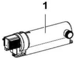
natural_image
Technical line drawing of a cylindrical mechanical component with labeled part '1' (no text or symbols beyond label)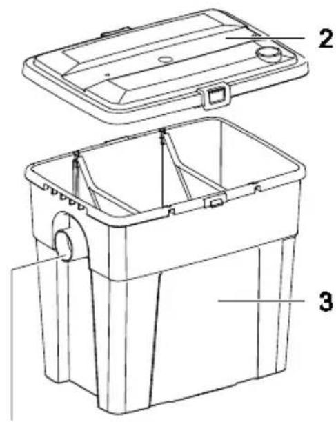
text_image
Technical diagram of a toolbox with labeled parts, showing open and closed views with numbered annotations.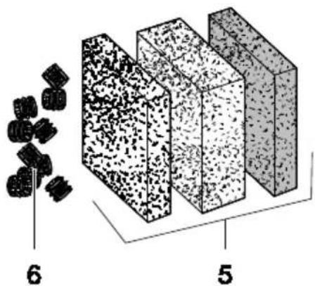
text_image
6 54
PondoVarlo 1500/2500
text_image
9 10
natural_image
Line drawing of a coiled cable with scissors, labeled with number 11 (no text or symbols on the diagram itself)
l = 3 m
∅ = 19 mm (%")
MCR0011
text_image
B 1. 2. 3. 4. 5. 6. MCR0002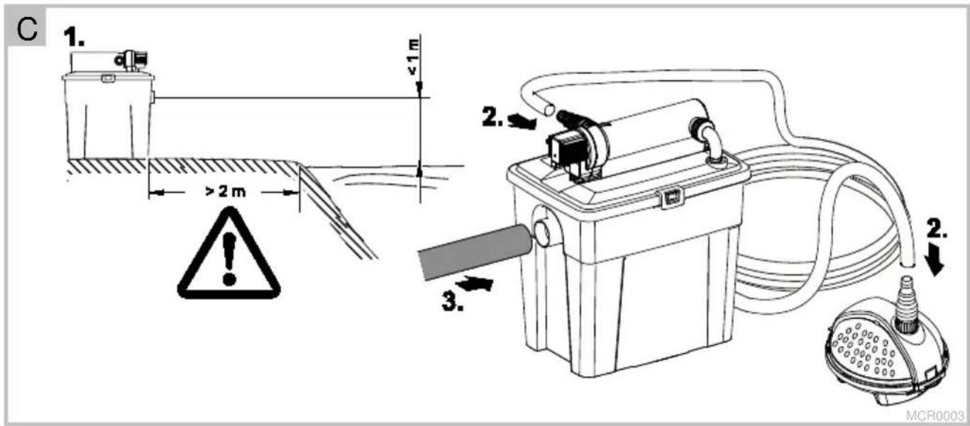
text_image
C 1. >2 m ≤1 m 2. 3. 2. MCR0003
natural_image
Technical line drawing of a welding torch with magnified detail view (no text or symbols)E
MCR0005
F
natural_image
Mechanical assembly diagram showing a cylindrical device with attached components and a numbered arrow indicating direction (no text or symbols present)MCR0006
G
text_image
Technical diagram showing three-step assembly steps of a mechanical device with labeled components and directional arrows.MCR0007
H
text_image
Technical diagram showing two-step assembly of a tool with labeled parts and motion arrows

natural_image
Illustration of a hand holding a tool with a mechanical component, showing a step 3 (no text or symbols present)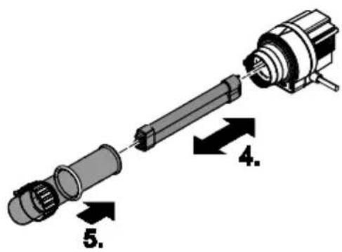
text_image
Diagram of a mechanical assembly with numbered components, likely illustrating a pin or shaft assembly.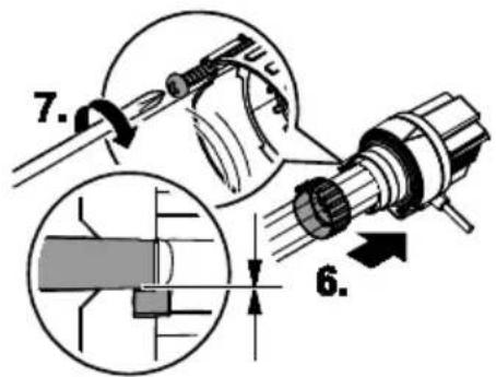
text_image
7. 6.PPS0008
Translation of the original Operating Instructions

WARNING
- This unit can be used by children aged 8 and above and by persons with reduced physical, sensory or mental capabilities or lack of experience and knowledge if they are supervised or have been instructed on how to use the unit in a safe way and they understand the hazards involved.
- Do not allow children to play with the unit.
- Only allow children to carry out cleaning and user maintenance under supervision.
- Ensure that the unit is fused for a rated fault current of max. 30 mA by means of a fault current protection device.
- Only connect the unit if the electrical data of the unit and the power supply correspond. The unit data is to be found on the unit type plate, on the packaging or in this manual.
- Only operate the unit if no persons are in the water.
- Possible death or severe injury from electrocution! Before reaching into the water, disconnect all electrical units in the water from the mains.
- Do not use the unit if electrical cables or housings are damaged.
- A damaged connection cable cannot be replaced. Dispose of the unit.
Safety information
Correct electrical installation
- Electrical installations must meet the national regulations and may only be carried out by a qualified electrician.
- A person is regarded as a qualified electrician if, due to his/her vocational education, knowledge and experience, he or she is capable of and authorised to judge and carry out the work commissioned to him/her. This also includes the recognition of possible hazards and the adherence to the pertinent regional and national standards, rules and regulations.
- For your own safety, please consult a qualified electrician.
- Extension cables and power distributors (e.g. outlet strips) must be suitable for outdoor use (splash-proof).
• Minimum safety distance between the unit and the water: 2 m. - Protect the plug connection from moisture.
- Only connect the unit to a correctly fitted socket.
Safe operation
- Never carry or pull the unit by the electrical cable.
- Route cables such that they are protected from damage and do not present a tripping hazard.
- Only open the unit housing or its attendant components if this is explicitly specified in the operating instructions.
- Only carry out work on the unit that is described in this manual. If problems cannot be overcome, please contact an authorised customer service point or, if in doubt, the manufacturer.
- Only use original spare parts and accessories for the unit.
- Never carry out technical changes to the unit.
- The unit, the connections and plugs are not water-proof and must not be routed or installed in water.
- Ensure that the filter will not overflow. Danger of emptying the pond.
Information about these operating instructions
Welcome to OASE Living Water. You have made a good choice by purchasing this product Multi Clear Set 5000/8000. Prior to commissioning the unit, please read the instruction manual carefully and fully familiarise yourself with the unit. Ensure that any work on or with this unit is carried out according to this manual.
Adhere to the safety information for the correct and safe use of the unit.
Keep these instructions in a safe place. Please also hand over the instructions when passing the unit on to a new owner.
Warnings used in these instructions
The warning information is categorised by signal words, which indicate the extent of the hazard.

WARNING
- Indicates a possibly hazardous situation.
• Non-observance may lead to death or serious injuries.

CAUTION
- Indicates a possibly hazardous situation.
• Non-observance may lead to slight or minor injuries.

NOTE
Information for the purpose of clarification or for preventing possible damage to assets or to the environment.
Cross-references used in these instructions
5 A reference to a figure, e.g. figure A.
→ Reference to another section.
Scope of delivery
The parts included in the scope of delivery are inside the container and have to be removed first!
• To open the container → Installation.
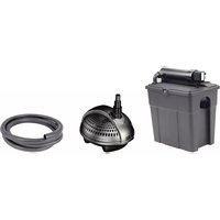
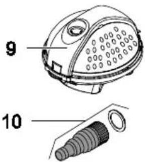
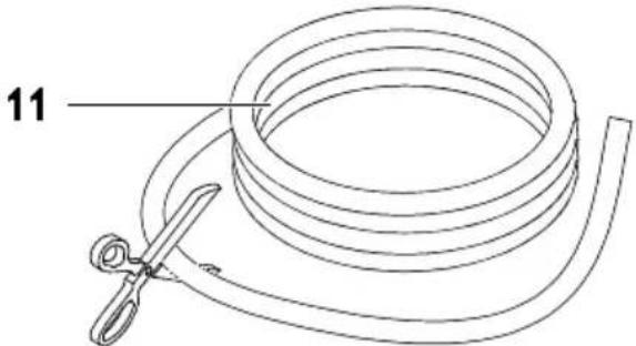
| 5 A | Multi Clear Set 5000/8000 | Quantity |
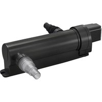
| 1 | UVC clarifying unitA UVC lamp in the unit irradiates and kills algae in the water. | 1 |
| 2 | Container cover | 1 |
| 3 | ContainerIt is delivered containing the UVC clarifying unit and an accessory kit with hose connector and O ring. | 1 |
| 4 | Outlet for fitting a DN 50 HT pipe or a 2" ∅ hose | 1 |
| 5 | - Coarse foam filter, fine foam filter and Japanese filter mat for mechanical cleaning, nitrification and denitrification of the water | 3 |
| 6 | Bio-surface elementsOnce colonised by bacteria, they act as filter elements for biologically cleaning the water. | 15 |
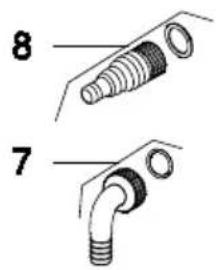
| 7 | Inlet elbow with sealing ringConnects the outlet of the UVC clarifying unit to the inlet of the filter container. | 1 |
| 8 | Stepped hose adapter with sealing ringFor connecting the hose to the inlet of the UVC clarifying unit | 1 |
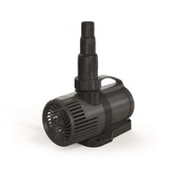
| 9 | Filter pump | 1 |
| 10 | Stepped hose adapter with sealing ringFor connecting the 20 mm ∅ hose | 1 |
| 11 | HoseConnects the UVC clarifying unit to the filter pump | 1 |
Product Description
Properties
Multi Clear Set 5000/8000 is a compact flow-through filter with bio-mechanical filter media and UVC clarifying unit.
- The UVC clarifying unit effectively kills floating algae.
- Multi-chamber filter with two walls separating the chambers that optimise the flow inside the filter, and four different filter media (Japanese filter mat, coarse and fine foam filters, bio-surface elements).
Intended use
Multi Clear Set 5000/8000, referred to as "unit", may only be used as specified in the following:
- For mechanical and biological cleaning of garden ponds
- For operation with clean water.
- Operate in accordance with instructions.
The following restrictions apply to the unit: - Do not use in swimming ponds.
- Never use the unit with fluids other than water.
- Never run the unit without water.
- Never operate the UVC lamp outside the casing or use it for any other purposes. The UVC radiation is harmful to the eyes and skin even in small doses.
- Do not use for commercial or industrial purposes.
- Do not use in conjunction with chemicals, foodstuff, easily flammable or explosive substances.
Assembly
The parts included in the scope of delivery are inside the container and have to be removed first!
How to proceed:
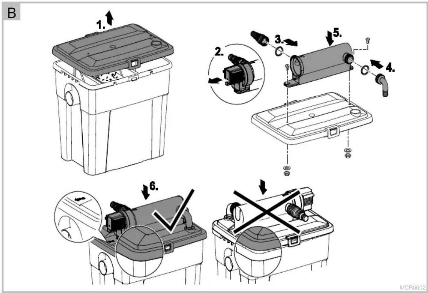
5 B
- Undo the fasteners on both sides of the container cover and lift off the container cover.
- Take out the UVC clarifying unit. (‡ Cleaning the UVC clarifying unit)
- Screw the stepped hose adapter including sealing ring onto the UVC inlet.
- Screw the inlet elbow including sealing ring onto the UVC outlet.
- Place the UVC water housing onto the container cover and fasten with both screws, washers and nuts.
- Insert the screws through the guides on the UVC water housing and the holes in the container cover.
- Place the container cover onto the container and carefully press down until the fasteners engage.
- Fit the UVC clarifying unit. (‡ Cleaning the UVC clarifying unit)
Installation and connection
- Do not expose the unit to direct sunlight.
– Maximum ambient temperature: 40 °C.
How to proceed:
5 C
- Place the filter container in a flood protected position on firm and level ground at least 2 m from the edge of the pond.
– Ensure that the outlet is not more than 1 m above the surface of the pond.
- Ensure that the unit is easily accessible for maintenance and cleaning.
-
Connect the hose to the UVC clarifying unit (stepped hose adapter at the inlet) and to the filter pump (stepped hose adapter at the outlet).
-
Connect e.g. an HT pipe (DN 50) or a 2" hose with a hose clip to the filter container outlet.
Commissioning/start-up

WARNING
Possible death or severe injury from hazardous electrical voltage!
- Prior to reaching into the water, isolate (switch off and disconnect) all units/devices used in the water.
- Isolate the device (disconnect from the power supply) before carrying out any work on it.
How to proceed:
5 D
- First switch on the pump, then the UVC clarifier.
- The UVC clarifying unit is designed to be operated with water passing through it. Never operate the unit without water.
- Switching on: Insert the power plug into the socket.
- The unit switches on immediately.
- The control lamp is lit.
- Check all connections for leaks.
- Switching off: Disconnect the power plug.

NOTE!
- Following installation it takes several weeks for the bacteria to become established and for the filter to become fully effective.
- Increased bacterial activity starts at a water temperature of approx. + 10 °C.
- A temperature monitor switches the UVC lamp off automatically if it overheats and on again once it has cooled down.

NOTE!
- The installed temperature monitor automatically turns the UVC clarifying lamp off, if it is overheated. The UVC lamp will automatically switch on again once cooled down
Remedy of faults
| Malfunction | Cause | Remedy |
| The unit performance is not satisfactory | Unit has been in operation only for a short time | The complete biological cleaning effect is only achieved after several weeks |
| Water extremely soiled | Remove algae and leaves from the pond, perform a partial water change | |
| Excessive fish and animal population | Guide value: approx. 60 cm fish length in 1 m3 pond water | |
| Foam filters soiled | Clean filters | |
| Pump filter housing soiled | Clean pump filter housing | |
| Impeller unit blocked | Clean pump | |
| Quartz glass tube soiled | Remove UVC and clean quartz glass | |
| UVC lamp capacity exhausted | Replace the lamp after approx. 8000 operating hours | |
| UVC lamp display is not lit | Power supply of UVC not connected | Connect UVC power plug |
| UVC lamp defective | Replacing the UVC lamp | |
| Connection defective | Check electrical connection | |
| UVC overheated | UVC automatically switches on when cooled down | |
| No water outlet from the pond inlet | Pump power supply not connected | Connect pump power supply |
| Pond inlet blocked | Clean pond inlet |
Wear parts
- Filter media
• UVC lamp, quartz glass and O ring for quartz glass
Maintenance and cleaning
Carry out the cleaning and servicing measures described in the following at regular intervals in order to ensure proper function of the individual units. The cleaning cycle depends on the degree of soiling/pollution of the garden pond. Follow the warning and safety information!

WARNING
Possible death or severe injury from hazardous electrical voltage!
- Prior to reaching into the water, isolate (switch off and disconnect) all units/devices used in the water.
- Isolate the device (disconnect from the power supply) before carrying out any work on it.
Cleanfilter
How to proceed:
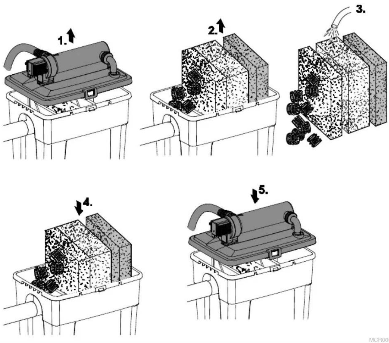
5 E
- Undo the fasteners on both sides of the container cover and lift off the container cover.
- Remove all filter media.
- Clean the foam filters by firmly squeezing them under running water. Rinse the bio-surface elements under running water. Clean the container.
- Place the foam filters into the container and return the bio-surface elements to the chamber on the outlet side.
- Ensure that the foam filters are replaced in the correct order.
- Place the container cover onto the container and carefully press down until the fasteners engage.
Clean UVC clarifier

CAUTION
The ultra-violet radiation of the UVC lamp can burn your eyes and skin.
- Never operate the UVC lamp outside its casing.
- Never operate the UVC lamp in a casing that is defective.

CAUTION
Quartz glass and UVC lamp can break and cause cut injuries.
- Handle the quartz glass and UVC lamp with care.

NOTE
For safety reasons, the UVC lamp can only be switched on when the unit head has been correctly fitted into the casing.
Removing the UVC clarifying unit and cleaning the quartz glass tube
How to proceed:
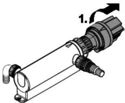
5 F
- Turn the UVC clarifying unit counter-clockwise against the stop (bayonet closure), then carefully pull it out of the cover together with the O ring.
- Check the quartz glass for damage and replace if necessary. (‡ Replacing the UVC lamp)
- Clean the quartz glass outer surface with a damp cloth.
Fitting the UVC clarifying unit
How to proceed:
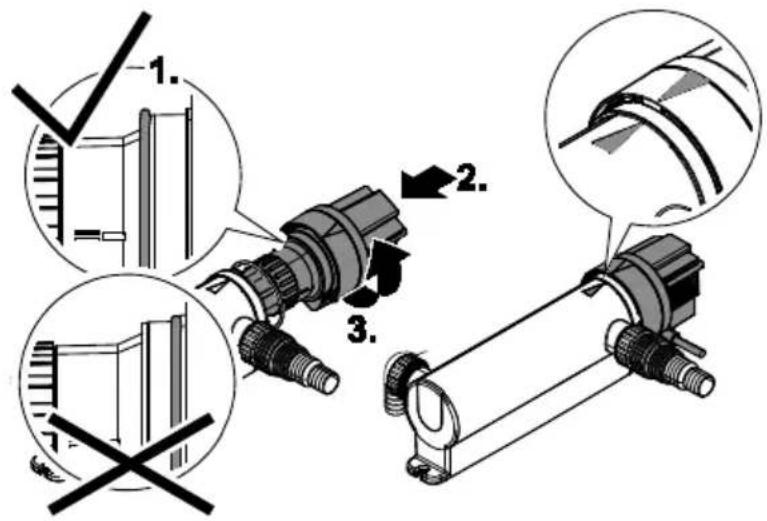
5 G
- Check the O ring at the unit head for damage and replace if necessary.
- Carefully push the quartz glass into the opening and the unit head onto the housing.
- Ensure that the tenons of the housing engage in the grooves of the bayonet closure.
- Turn the unit head clockwise against the stop while applying slight pressure.
- Ensure that the arrows on the UVC unit head and UVC water housing are aligned.
Exchange the UVC lamp
Replace the UVC lamp after max. 8000 operating hours.
- To replace the UVC lamp, remove the UVC clarifying unit and refit after completion of the work. (→ Cleaning the UVC clarifying unit)
- Ensure that the identification and capacity data of the lamps used correspond to the information on the unit type plate. (→ Technical data)
- Prior to inserting the UVC lamp, check the quartz glass and O ring for damage and replace if necessary.
How to proceed:
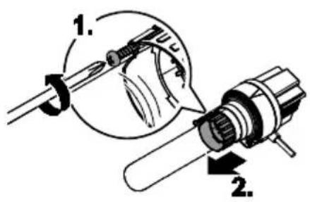
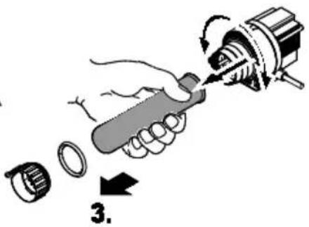
5 H
- Loosen the self-tapping screw until the the screw tip is sunk in the housing of the clamping screw.
- Unscrew the clamping screw counter-clockwise.
- Remove the quartz glass including the O ring towards the front with a slight turning movement.
- Pull out the UVC lamp and replace.
- Push the quartz glass including the O ring as far as the stop in the unit head.
– Clean the O ring, replace if damaged. -
Ensure that the O ring is located in the gap between the unit head and the quartz glass.
-
Tighten the clamping screw clockwise up to the stop.
- Tighten the self-tapping screw.
Storage/overwintering
Take the unit out of operation at water temperatures below +4 °C or, at the latest, when freezing temperatures are to be expected.
- Drain the unit as far as possible, clean thoroughly and check for damage.
• Empty all hoses, pipes and connections as far as possible.
Disposal
| Use our return system for disposal. Always make electrical units unusable by cutting the cables! | Disposal with the household waste: |
| UVC unit (electronics!) | Packaging |
| UVC lamp (mercury!) | Worn foam filters, sealing rings |
| Filter container |
Guarantee conditions
PfG grants a 2 year guarantee from the date of sale on proven material and manufacturing faults. Wear parts such as bulbs etc. are exempted from the guarantee. Prerequisite for our guarantee is the presentation of the purchase receipt. Our guarantee will become null and void if the unit is misused, electrically or mechanically damaged by inappropriate use and improper repair by non-authorised workshops. Repairs are reserved for workshops authorised by PfG or by PfG itself. In the case of warranty claims, please return the defective unit or part freight paid to PfG together with a description of the fault and the purchase receipt. PfG reserves the right to invoice repair costs. PfG is not liable for transport damage. Any damage must be claimed against the carrier. Further claims of whatever type, especially consequential damage, are excluded. This guarantee does not affect the final customer's claims against the dealer.
text_image
Technical diagram of a battery storage system with labeled components and assembly stepsMCR0008

text_image
pontecPIG GmbH Tecklenburger Straße 161 D - 48477 Hörstel Germany www.pontec.com
CE