USER MANUAL Robolinho 350 W AL-KO
AL-KO KOBER GROUP Kottz, Germany
This documentation or excerpts therefrom may not be reproduced or disclosed to third parties without the express permission of the AL-KO KOBER GROUP.
15
*: see technical data
| Robolinho
350 W | Robolinho
550 W | Robolinho
1300 W | Robolinho
520 W | Robolinho
822 W | Robolinho
1423 W | Robolinho
2323 W |
| 123032 123033 123034 127695 127696 127697 127698 |
| 630 x 430 x
270 mm | 630 x 430 x
270 mm | 630 x 430 x
270 mm | 630 x 430 x
270 mm | 630 x 430 x
270 mm | 630 x 430 x
270 mm | 630 x 430 x
270 mm |
| max. 350 m² | max. 550 m² | max. 1300 m² | max. 500 m² | max. 800 m² | max. 1400 m² | max. 2300 m² |
| 30 % (17°) 45 % (24°) 45 % (24°) 35 % (19°) 45 % (24°) |
| 30 % (17°) 45 % (24°) 45 % (24°) 30 % (17°) 45 % (24°) |
| 0-55 °C |
| 200 mm 200 mm 220 mm 200 mm 220 mm 230 mm 230 mm |
| 25-55 mm |
| IPX1 |
| 6,4 kHz |
| 8,55 kHz |
| 10 m: < 70 dBμA/m |
| max. 3400 min-1 | Standard: 3400 min-1
Eco-Mode: 3200 min-1 |
| max. 60 dB(A) |
| Oi | Robolinho
350 W | Robolinho
550 W | Robolinho
1300 W | Robolinho
520 W | Robolinho
822 W | Robolinho
1423 W | Robolinho
2323 W |
| kg | 8,0 kg 8,5 kg | 8,9 kg 8,0 kg | 8,5 kg 8,9 kg | kg | | | |
| 90 90 180 | | | - - - - | | | |
| 100 m 130 m | 150 m | | - - - - | | | |
| * | -X-X | | | |
| - | X |
| HOME on Base | - | X |
| Start | 1369 | | | |
x:included,notincluded
| Oo i | Robolinho
350 W | Robolinho
550 W | Robolinho
1300 W | Robolinho
520 W | Robolinho
822 W | Robolinho
1423 W | Robolinho
2323 W |
| Li-Ion
18 V /
2,2 Ah /
39,6 Wh | Li-Ion
20 V /
2,5 Ah /
50 Wh | Li-Ion
25,2 V /
5 Ah /
126 Wh | Li-Ion
18 V /
2,2 Ah /
39,6 Wh | Li-Ion
20 V /
2,5 Ah /
50 Wh | Li-Ion
25,2 V /
5,0 Ah /
126 Wh | |
| IN: 230 V AC /
50 Hz
OUT:
24 V DC /
1,0 A / 24 W | IN: 230 V AC / 50 Hz
OUT: 36 V DC / 1,67 A / 60 W | IN: 230 V AC /
50 Hz
OUT:
24 V DC /
1,0 A / 24 W | IN: 230 V AC / 50 Hz
OUT: 36 V DC / 1,67 A / 60 W |
| WiFi | 100 mW
2400 MHz - 2483,5 MHz |
1 About these operating instructions. 35
1.1 Symbols on the title page 35
1.2 Legends and signal words 35
2 Product description 35
2.1 Scope of supply (01) 35
2.2 Automatic lawn mower (02) 36
2.3 Symbols on the appliance 36
2.4 Control panel (03) 36
2.5 Display 37
2.6 Menu structure 37
2.7 Base station (04) 38
2.8 Rechargeable battery 38
2.9 Functional description 39
2.10 WiFi radio module and AL-KO in-TOUCH Smart Garden app 39
3 Safety. 40
3.1 Intended use 40
3.2 Possible misuse 40
3.3 Safety and protective devices 40
3.3.1 PIN and PUK input 40
3.3.2 Sensors 40
3.4 Safety instructions 40
3.4.1Operator 40
3.4.2 Personal protective equipment.... 41
3.4.3 Safety of persons and animals.... 41
3.4.4 Appliance safety 41
3.4.5 Electrical safety 41
4Assembly 41
4.1 Unpacking the machine 41
4.2 Planning the mowing areas (05) 41
4.3 Preparing the mowing areas 42
4.4 Setting up the base station (07/a, 17) 42
4.5 Installing the boundary cable 42
4.5.1 Connecting the boundary cable to the base station (07/b) 42
4.5.2 Routing the boundary cable (05). 42
4.5.3 Excluding obstacles 43
4.5.4 Enclosing corridors (05/h) 43
4.5.5 Excluding downward slopes (15). 43
4.5.6 Creating loops of cable (11) 43
4.5.7 Typical faults in cable routing (06) 44
4.6 Connecting the base station to the power source (08) 44
4.7 Checking the connections on the base station (08) 44
4.8 Installing the Quick Homing kit 44
5 Start-up 44
5.1 Charging the rechargeable battery (12) 44
5.2 Making the basic settings 44
5.3 Setting the cutting height (14) 45
5.4 Carrying out an automatic calibration movement 45
6 Operation 46
6.1 Starting the appliance manually 46
6.2 Cancelling mowing 46
6.3 Mowing the secondary area (05/NF).. 46
7 Settings. 46
7.1 Calling up the setting - General 46
7.2 Activating/deactivating the button tones 46
7.3 Activating/deactivating Eco mode 46
7.4 Setting the rain sensor 46
7.5 Setting the mowing program 47
7.5.1 Setting the mowing program - General 47
7.5.2 Setting the start points 47
7.5.3 Setting the mowing times.. 47
7.5.4 Passage mode 48
7.6 inTOUCH 48
7.7 Edge mowing with a manual start 48
7.8 Setting the secondary area mowing... 48
7.9 Setting the display contrast 48
7.10 Setting lock. 48
7.11 Recalibrating 48
7.12 Restoring factory settings 49
8 Displaying information 49
9 Maintenance and care. 49
9.1 Cleaning 49
9.2 Regular checks 49
9.3 Replacing the cutting blades.. 50
10 Help in case of malfunction. 50
10.1 Correcting appliance and handling faults 50
10.2 Fault codes and troubleshooting.... 52
11 Transport 55
12 Storage 55
12.1 Storing the automatic lawn mower.... 55
12.2 Dismantling and storing the charging pole (18, 19) 55
12.3 Winter storage of the boundary cable 55
13 Disposal 55
14 After-Sales/Service 56
15 Information on the Declaration of Conformity 56
16 Warranty. 56
1 ABOUT THESE OPERATING INSTRUCTIONS
The German version is the original operating instructions. All additional language versions are translations of the original operating instructions.
- Keep these operating instructions in a safe place at all times so that they can be consulted if you need any information about the appliance.
Only pass on the appliance to other persons together with these operating instructions.
Comply with the safety and warning information in these operating instructions.
1.1 Symbols on the title page
Symbol Meaning

It is essential to read through these operating instructions carefully before start-up. This is essential for safe working and trouble-free handling.
Symbol Meaning

Operating instructions

Handle Li-Ion rechargeable batteries with care! In particular, observe the notes on transport, storage and disposal in these operating instructions!
1.2 Legends and signal words
DANGER! Denotes an imminently dangerous situation which will result in fatal or serious injury if not avoided.
WARNING! Denotes a potentially dangerous situation which can result in fatal or serious injury if not avoided.
CAUTION! Denotes a potentially dangerous situation which can result in minor or moderate injury if not avoided.
IMPORTANT! Denotes a situation which can result in material damage if not avoided.
NOTE Special instructions for ease of understanding and handling.
2 PRODUCT DESCRIPTION
This document describes a fully automatic, battery operated automatic lawn mower which moves freely on a grass surface. The cutting height can be adjusted.
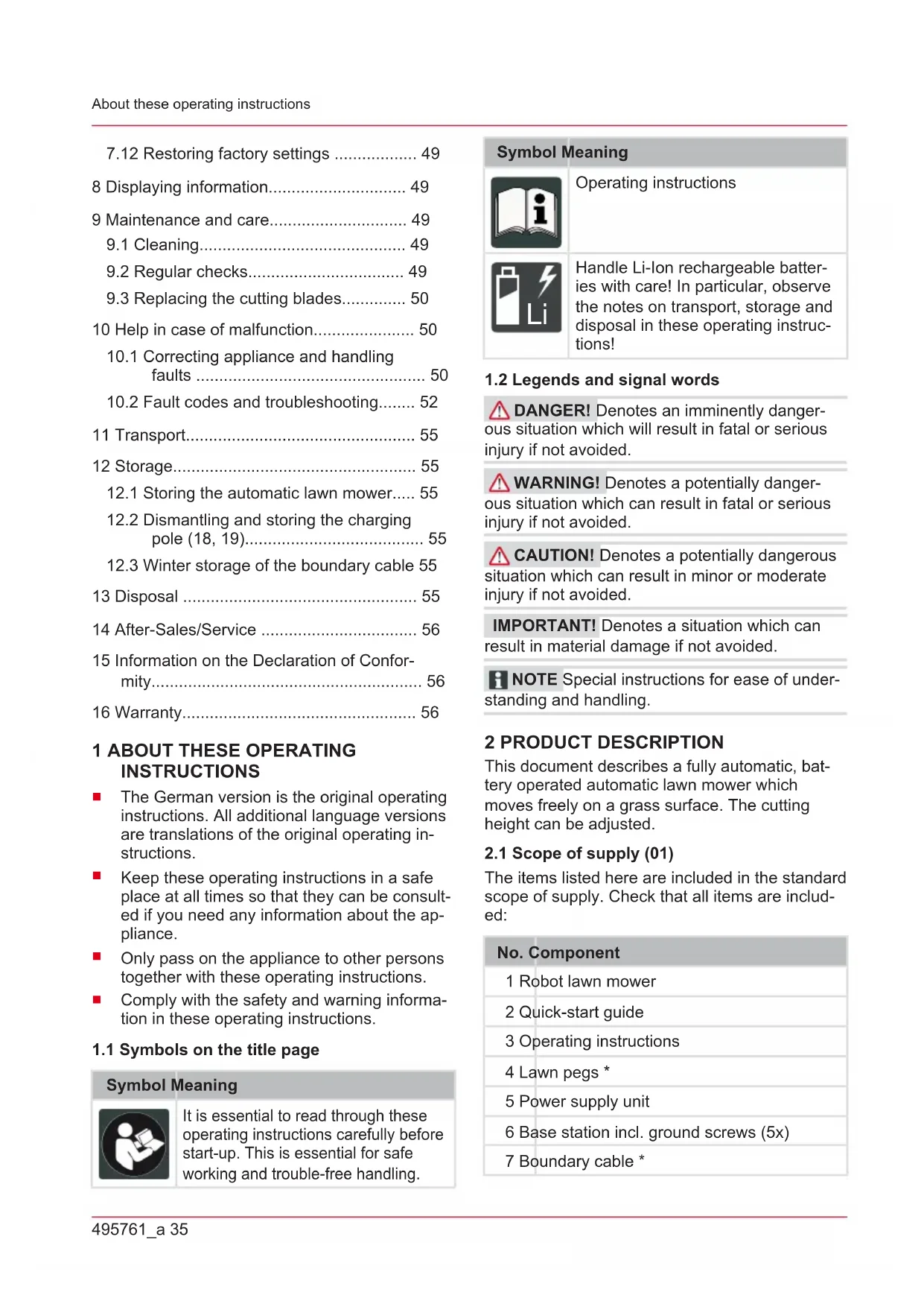
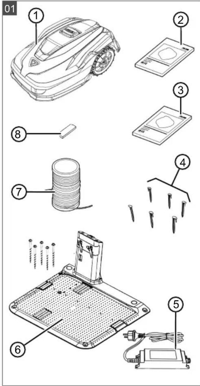
2.1 Scope of supply (01)
The items listed here are included in the standard scope of supply. Check that all items are included:
No. Component
1 Robot lawn mower
2 Quick-start guide
3 Operating instructions
4 Lawn pegs *
5 Power supply unit
6 Base station incl. ground screws (5x)
7 Boundary cable *
No. Component
8 Winter cover *
- model-dependent (see technical data)
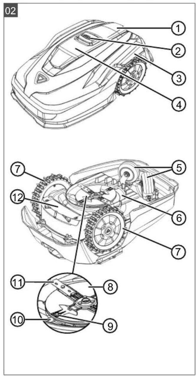
2.2 Automatic lawn mower (02)
No. Component
1 Control panel with display (interior)
2 STOP key (stops the appliance immediately and the cutting blade within 2 s)
3 Charging contacts
4 Height adjustment (interior)
5 Front rollers (steering)
6 Mower deck
7 Drive wheel
8 Blade plate
9 Fastening screw
10 Clearer blade
11 Cutting blade
12 Rechargeable battery compartment
2.3 Symbols on the appliance
Symbol Meaning
Risk of injury and risk of material damage due to objects being discharged!

Pay special attention when handling this appliance!
Keep your hands and feet away from the blade system!
Maintain a safety distance!

Read the operating instructions before starting operation!
Symbol Meaning
Enter the PIN in order to start the appliance.
Do not ride on the appliance!
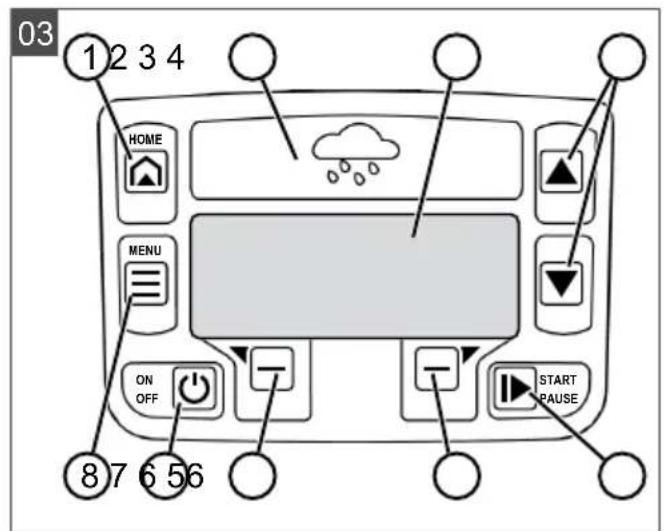
2.4 Control panel (03)
No. Component
1
(home button): Cancel mowing, the appliance returns to its base station. It starts on the next day automatically again at the set mowing time.
2 Rain sensor: Registers if it rains (see chapter 7.4 "Setting the rain sensor", page 46).
3 Display: Shows the current operating status of the appliance, the name of the selected menu, its menu items and the functions to be selected. (see chapter 2.5 "Display", page 37).
4
arrow keys): Select menu items, increase and decrease numerical values, select between settings.
5
Press 1x: Start and interrupt mowing manually.
Press 2x: Immediately recommencemowing after pressing the Home button.
6
function keys): Call up the function displayed directly above the button on the display.
7
On/Off button): Switch the appliance on and off.
8
(menu button): Call up the main menu.
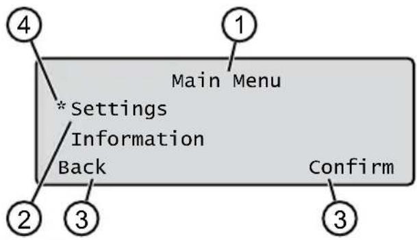
2.5 Display
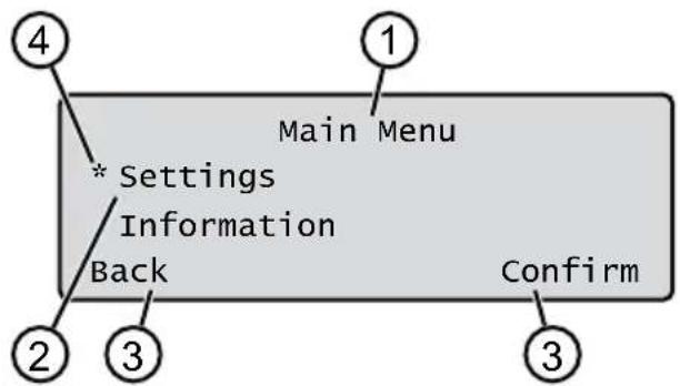
No. Display
1 Name of the selected menu (here: Main Menu)
No. Display
2 Menu items in the menu: Only two menu items are ever displayed (here: Settings and Information). Further menu items can be displayed with and
3 Functions for the selected menu item (here: Settings). Further functions can be called up with and
4 Asterisk for marking the displayed menu item (here: Settings)
Main Menu
Programs
Weekly Program see chapter 7.5 "Setting the mowing program", page 47
Entry Point see chapter 7.5.2 "Setting the start points", page 47
Program Info see chapter 8 "Displaying information", page 49
Settings
Time see chapter 5.2 "Making the basic settings", page 44
Date see chapter 5.2 "Making the basic settings", page 44
Language see chapter 5.2 "Making the basic settings", page 44
PIN-Code see chapter 5.2 "Making the basic settings", page 44
Key clicks see chapter 7.2 "Activating/deactivating the button tones", page 46
EcoMode see chapter 7.3 "Activating/deactivating Eco mode", page 46
Quick Homing Kit see chapter 4.8 "Installing the Quick Homing kit", page 44
Rain sensor see chapter 7.4 "Setting the rain sensor", page 46
After rain delay see chapter 7.4 "Setting the rain sensor", page 46
Rain sensitive see chapter 7.4 "Setting the rain sensor", page 46
inTOUCH see chapter 7.6 "inTOUCH", page 48
Margin mowing see chapter 7.7 "Edge mowing with a manual start", page 48
Sub zone active/disabled see chapter 7.8 "Setting the secondary area mowing", page 48
Display contrast see chapter 7.9 "Setting the display contrast", page 48
Safety settings see chapter 7.10 "Setting lock", page 48
Reset calibration see chapter 7.11 "Recalibrating", page 48
Factory reset see chapter 7.12 "Restoring factory settings", page 49
Blades service see chapter 8 "Displaying information", page 49
Hardware see chapter 8 "Displaying information", page 49
Software see chapter 8 "Displaying information", page 49
Program Info see chapter 8 "Displaying information", page 49
Failures see chapter 8 "Displaying information", page 49
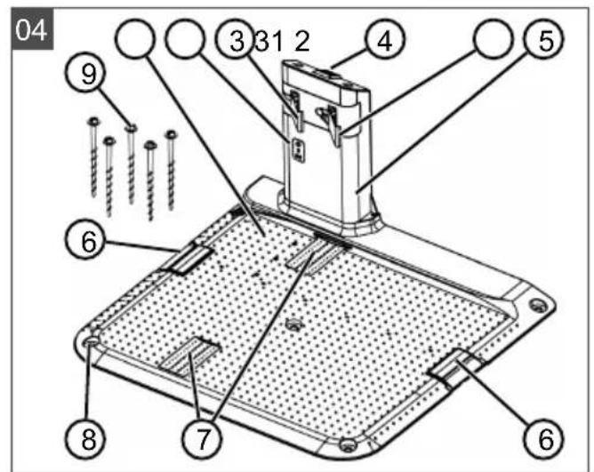
2.7 Base station (04)
| No. Component |
| 1 Base plate |
| 2 LED for status display |
| 3 Charging contact |
| 4 | Home button |
| 5 Charging station |
| 6 Cable shaft |
| 7 Wheel recess |
| 8 Hole for ground screws (9) |
| 9 Ground screws |
- model-dependent (see technical data)
2.8 Rechargeable battery
The rechargeable battery can be changed by the user.
NOTE Fully charge the rechargeable battery before using it for the first time. The rechargeable battery can be charged in any charge status. Interrupting charging does not damage the rechargeable battery. The rechargeable battery can only be charged after the appliance has been switched on.
The rechargeable battery is partially charged on delivery. The rechargeable battery is regularly recharged during normal operation. The appliance returns to its base station for this.
The integrated electronic control unit with a monitoring function terminates the charging procedure when a 100% charge status is reached.
The charging process only functions with perfect contact of the charging contacts on the base station with the contact surfaces of the appliance.
The built-in protection circuit prevents the rechargeable battery from being charged at temperatures above 45^ . This prevents irreparable damage to the rechargeable battery.
If the operating time of the rechargeable battery becomes shorter despite being fully charged, replace the battery.
If the battery charge level has dropped below the threshold set by the manufacturer as a result of ageing or excessively long storage, this means it can no longer be recharged. Have the battery and the monitoring electronic control unit checked by an AL-KO dealer, technician or service partner, and replace them if necessary.
The rechargeable battery status is shown on the display. Check the rechargeable battery status after about 3 months in storage. To do so, switch on the appliance and read off the rechargeable battery status. If the rechargeable battery is now only charged to approx. 30% or less, place the appliance in the base station and switch it on so the rechargeable battery is charged. If the charging station was removed to store the base station (see chapter 12.2 "Dismantling and storing the charging pole (18, 19)", page 55), first mount it again in reverse order and connect the base station to the mains supply again.
If electrolyte has escaped into the battery compartment: Have the appliance repaired by an AL-KO service centre.
If the rechargeable battery has been removed from the appliance: If the eyes or hands have come into contact with escaped electrolyte, flush them immediately with water. Immediately consult a doctor.
2.9 Functional description
Moving on the grass surface
The appliance moves freely in a mowing area delimited by a boundary cable. The appliance is oriented by means of the sensors that detect the electromagnetic field of the boundary cable.
If the appliance encounters an obstacle, it stops and then continues in another direction. If the appliance gets into a situation where it cannot operate, this is indicated by a message on the display.
If the appliance detects moisture when the rain sensor is switched on, it automatically returns to the base station.
Mowing and charging
The mowing phases alternate constantly with the charging phases. If the charge of the rechargeable battery drops to a specific value (display: 0% ) during mowing, the appliance returns to the base station along the boundary cable.
Mowing programs are preset and can be customised on the appliance or in the app.
Each time the mowing motor is started, its direction of rotation is changed which doubles the service life of the cutting blades.
2.10 WiFi radio module and AL-KO inTOUCH Smart Garden app
The robot lawn mower is equipped with a WiFi radio module. This allows convenient control, setting and monitoring via app from a mobile device (smartphone, tablet, etc.).
NOTE The mobile device being used requires an Internet connection in order to use the AL-KO inTOUCH Smart Garden app.
NOTE In order to ensure that the latest software version is always installed on the robot lawn mower, it must be connected to the Internet via a WiFi network. The AL-KO inTOUCH Smart Garden app notifies you when there are new software updates for the robot lawnmower. They are downloaded automatically.
AL-KO inTOUCH Smart Garden app
The AL-KO inTOUCH Smart Garden app can be downloaded for Android-based devices from the
Google Play Store and for iOS-based devices from the Apple App Store:


Scan this QR code to find out how to install the AL-KO inTOUCH Smart Garden app on your smartphone and obtain further information on your appliance. You can also use the app to connect your smart-connected appliance to the Internet.
NOTE The robot lawnmower connects to a 2.4 GHz WLAN only. 5 GHz WLAN networks are not supported.
In order to connect your WiFi-enabled robot lawnmower to the AL-KO inTOUCH Smart Garden app, the robot lawnmower and smartphone must be within range of a WiFi router with sufficient signal strength (recommendation: min. 50% ).
- Start the AL-KO inTOUCH Smart Garden app.
- Create a user account once:
Press "Login / Register" > "Register".
Enter your e-mail address and password.
Check the "Read and agreed..." check-box.
Press the "Register" button.
- Log in with the previously created user account.
- Start the connection wizard by pressing "Add new device".
- Follow the further instructions.
NOTE If the robot lawnmower moves into an area of the garden with a poor or no WiFi signal, the settings of the AL-KO inTOUCH Smart Garden app will only be carried out when the robot lawnmower returns to an area with a good signal. If the WiFi signal from the router is too weak over the whole garden, its range can be extended with a commercially available repeater.
In the event of malfunctions, a dealer with the AL-KO inTOUCH Smart Garden app installed can help you. The robot lawnmower must be enabled for the dealer via the AL-KO inTOUCH Smart Garden app.
In addition to remote access to connected robot lawn mowers, the AL-KO inTOUCH Smart Gar
den app offers other functions such as links to other AL-KO appliances or push notifications in the event of a fault.
3 SAFETY
3.1 Intended use
This appliance is intended solely for use in non-commercial applications. Any other use as well as unauthorised conversions or modifications are regarded as contrary to the intended use and will result in voiding of the warranty as well as loss of conformity; the manufacturer will thus decline any responsibility for damage and/or injury suffered by the user or third parties.
The application limits of the appliance are: see technical data.
3.2 Possible misuse
This machine is not suitable for use in public gardens, parks, sports stadiums, and in agriculture and forestry.
3.3 Safety and protective devices
WARNING! Risk of injury. Defective and disabled safety and protective devices can result in serious injury.
Have any defective safety and protective devices repaired.
Never disable safety and protective devices.
The appliance can only be started by entering a PIN (Personal Identification Number). This prevents the appliance from being switched on by unauthorised persons. The factory setting of the PIN is 0000. The PIN can be changed, see chapter 5.2 "Making the basic settings", page 44.
If the PIN is entered incorrectly 3 times, the PUK (Personal Unlocking Key) must be entered. If this is also entered incorrectly, the user must wait 24 hours until entering it again.
- Keep the PIN and PUK so that they are inaccessible to unauthorized persons.
3.3.2 Sensors
The appliance is provided with several safety sensors. It does not restart automatically after being switched off by a safety sensor. The error message is shown on the display and must be acknowledged. The reason for the triggering of the sensor must be resolved.
Lifting sensor
If the appliance is raised by the housing during operation, the travel drive switches off and the cutting blades are stopped.
Bump sensors for obstacle detection
The appliance is equipped with sensors that ensure it changes its direction of travel if it encounters obstacles. When it encounters an obstacle, the top part of the deck is shifted slightly and the shock sensor triggered.
Tilt sensor in direction of travel/sideways
If an upward or downward slope or a laterally inclined angle that is larger than the value set for the model is reached in the direction of travel, the appliance is turned or the appliance changes its direction of travel.
Rain sensor
Depending on the model, the appliance is equipped with a rain sensor that (when activated) interrupts the mowing procedure in case of rain and ensures that the appliance returns to the base station (see technical data).
Frost sensor
The appliance is equipped with a frost sensor which, at low temperatures, displays a message on the appliance or transmits a push message to the AL-KO inTOUCH Smart Garden app (see Technical data). The temperature for the message is variable.
Electromagnetic emissions

The appliance can be operated reliably in the immediate vicinity of other robot lawn mowers (distance 0.5m
The signal used in the boundary cable complies with the standard defined by the European Garden Machinery Industry Federation (EGMF) with regard to electromagnetic emissions.
3.4 Safety instructions
3.4.1 Operator
- Young people under 16 years of age, persons with limited physical, sensory or mental abilities or with a lack of experience and knowledge and persons who do not know the operating instructions must not use the device. Heed any country-specific safety regulations concerning the minimum age of the user.
- Do not operate the appliance if you are under the influence of alcohol, drugs or medication.
3.4.2 Personal protective equipment
Wear clothing and protective equipment in accordance with the regulations in order to avoid injury.
The personal protective equipment comprises:
Long trousers and sturdy shoes.
During maintenance and care: Protective gloves.
3.4.3 Safety of persons and animals
In areas accessible to the public, post warning signs with the following content around the mowing area:
IMPORTANT! Automatic lawn mower in operation! Do not approach the appliance! Supervise children!
Make sure that persons, in particular children, and animals are not in the vicinity of the appliance, do not climb onto and do not play with the appliance when it is in operation.
Sitting on the appliance and reaching into the cutting blades is forbidden!
- Keep limbs and clothing away from the cutting unit.
3.4.4 Appliance safety
Before working, make sure that there are no objects (e.g. branches, glass or metal pieces, and items of clothing, stones, garden furniture, garden utensils or toys) in the work area of the appliance. They can damage the cutting blade of the appliance or can be damaged by the appliance.
Only use the appliance under the following conditions:
The appliance is not soiled.
The appliance shows no damage or wear.
All controls function properly.
The base station and power supply as well as their electrical supply cables are undamaged and function properly.
Always replace defective parts with original spare parts from the manufacturer.
Have the appliance repaired if it has been damaged.
The user of the appliance is responsible for accidents of the appliance involving other persons or their property.
3.4.5 Electrical safety
- Never operate the appliance when a lawn sprinkler is operating on the mowing area at the same time.
Do not spray the appliance with water.
Do not open the appliance.
4 ASSEMBLY
4.1 Unpacking the machine
- Open the packaging carefully.
- Carefully remove all components from the packaging and check for transport damage.
Note: Notify your AL-KO dealer or service partner immediately if any transport damage is discovered.
- Check the scope of supply, see chapter 2.1 "Scope of supply (01)", page 35.
If the appliance is going to be sent on, retain the original packaging and accompanying documents. They will also be required for return shipment.
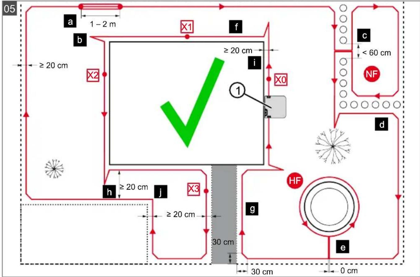
4.2 Planning the mowing areas (05)
Location of the base station (05/1)
Shortest possible distance to the largest mowing area
Level surface
Protected against direct sunlight and harsh weather conditions
Connection option for power source
Free accessibility to the robot lawn mower
Routing the boundary cable (05)
The boundary cable must be laid in a continuous loop in a clockwise direction.
Corridors between mowing areas (05/h)
A corridor is a narrow section in the grass surface and can be used to connect two mowing areas.
Main area and secondary area(s) (05)
Main area (05/HF): This is the grass surface on which the base station is located and whose entire surface can be mowed automatically by the appliance.
Secondary area (05/NF): If a grass surface cannot be reached by the appliance from the main area, carry the appliance to the secondary area by hand if necessary. Secondary areas can be processed using manual operation.
The main area and secondary areas are bounded by the same continuous boundary cable, however.
Location of start points (05/X0 - 05/X3)
At the specified mowing time, the appliance moves along the boundary cable to the specified start point and begins to mow there.
The start points can be used to specify which areas of the mowing area are to be mowed several times.
4.3 Preparing the mowing areas
- Check that the grass surface is larger than the area covered by the appliance. If the grass surface is too large, an irregularly mown lawn will result. Reduce the size of the grass surface to be mowed if necessary.
- Before installation of the base station and boundary cable or start-up of the appliance: Use a lawn mower to mow the grass surface to a low cutting height.
- Remove any obstacles on the grass surface or exclude them with the boundary cable (see chapter 4.5.3 "Excluding obstacles", page 43):
Flat obstacles that will be run over and could damage the cutting blade (e.g. flat stones, transitions from the grass surface to the terrace or paths, plates, kerbs, stones, etc.)
Holes and protrusions in the grass surface (e.g. molehills, burrowing holes, pine cones, fallen fruit, etc.)
- Steep upward or downward slopes that are larger than the values specified in the technical data
- Bodies of water (e.g. ponds, streams, swimming pools, etc.) and their demarcation to the grass surface
Shrubs and hedges that can become broader
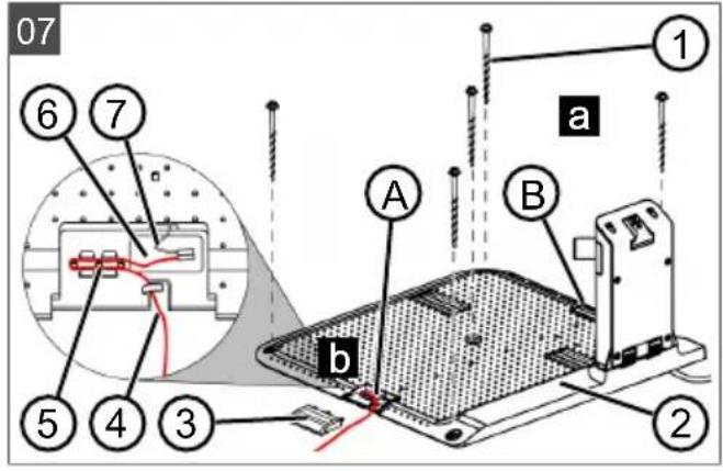
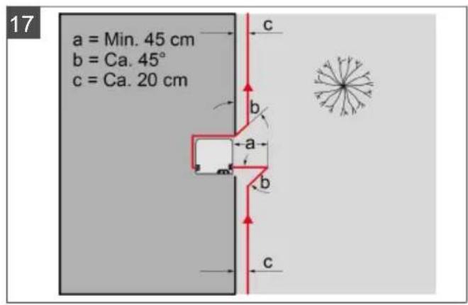
4.4 Setting up the base station (07/a, 17)
- Place the base station (05/1) at right angles to the planned location of the boundary cable as described below:
Level (check with spirit level)
Straight and level entrance and exit
Not arched (the charging pole must not bend or tilt during subsequent tightening of the ground screws)
- Fix the base station (07/2) to the ground with four ground screws (07/1).
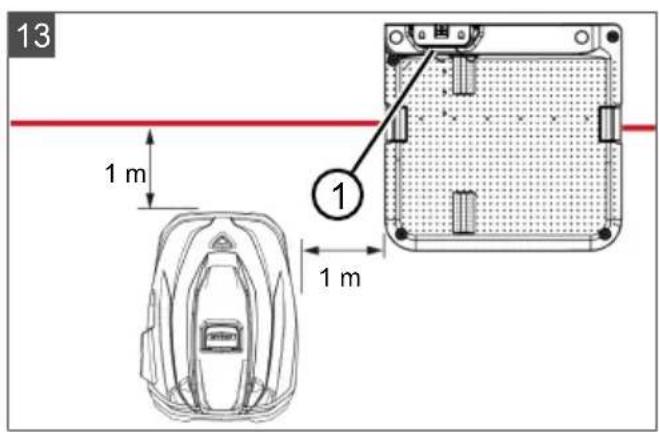
The base station can also be located outside the lawn area (17). In this case the boundary cable has to be routed as shown in the figure.
4.5 Installing the boundary cable
NOTE If the supplied boundary cable delivered with the model is too short, an extension cable can be obtained from your AL-KO dealer or service partner.
4.5.1 Connecting the boundary cable to the base station (07/b)
- Pull the boundary cable (07/4) out of the packaging.
- Remove the cover of the cable shaft (07/3) on the connection (07/A).
- Insulate the end of the boundary cable (07/6) and insert into the terminal (07/7).
- Close the terminal.
- Lead the boundary cable through the strain relief (07/5) out of the cable shaft with cable reserve.
NOTE The cable reserve allows smaller corrections to be carried out on the cable guide later.
- Place the cover on the cable shaft.
4.5.2 Routing the boundary cable (05)
The boundary cable can be laid on the lawn and as much as 10cm under the turf. The laying under the turf can be carried out by the dealer.
Both variants can be combined with one another.
IMPORTANT! Danger of damaging the boundary cable. If the boundary cable is damaged or cut, the transmission of the control signals to the appliance is no longer possible. In this case, the boundary cable must be repaired or replaced. The boundary cables are available from AL-KO.
Always route the boundary cable directly on the ground. If necessary, secure with an additional lawn peg.
- When laying the boundary cable and during operation, protect the boundary cable from damage.
Do not dig or scarify in the vicinity of the boundary cable.
1. Attach the boundary cable at regular intervals with lawn pegs or route it underground (at a max. depth of 10cm ).
- Route the boundary cable around obstacles: see chapter 4.5.3 "Excluding obstacles", page 43.
- Create corridors between individual mowing areas: see chapter 4.5.4 "Enclosing corridors (05/h)", page 43.
- Exclude excessive upward or downward slopes: see chapter 4.5.5 "Excluding downward slopes (15)", page 43.
- Create loops of cable: see chapter 4.5.6 "Creating loops of cable (11)," page 43.
- After completing the routing of the boundary cable, connect to the connector (07/B) of the base station: see chapter 4.5.1 "Connecting the boundary cable to the base station (07/b)", page 42.
4.5.3 Excluding obstacles
Depending on the surroundings of the working area, the boundary cable must be routed at different distances to obstacles. Use the ruler that can be removed from the packaging to determine the correct distance.
NOTE Exclusions are only necessary if they cannot be detected by the bump sensors of the appliance. Avoid too many or unnecessary exclusions. Recesses that are smaller than 6cm must be excluded, otherwise the appliance may cause damage.
Distance from walls, fences, beds: min. 20 cm (05)
The appliance moves along the boundary cable with an offset of 20~cm to the outside. Therefore, route the boundary cable at a distance of at least 20~cm from walls, fences, beds, etc.
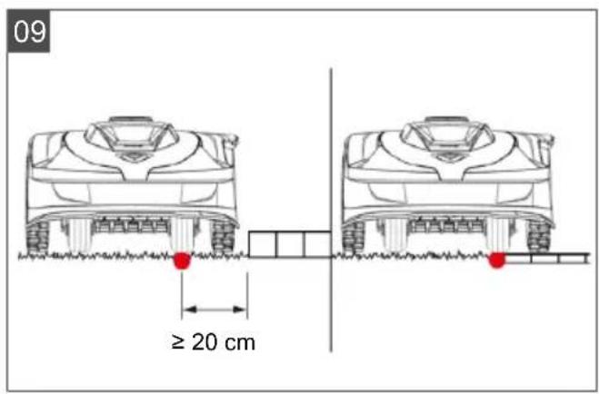
Distance from terrace edges and paved paths (09)
If the terrace or path edge is higher than the grass surface, a distance of at least 20~cm must be complied with. If the edge of the terrace or path is at the same height as the grass surface, the cable can be routed exactly along the edge.
Distance of obstacles from the boundary cable (05)
If the boundary cables are precisely folded up away from the obstacle or towards the obstacle, i.e. distance 0cm the appliance moves beyond the boundary cable. Do not cross the boundary cables (06/c), but lay them parallel (05/e).
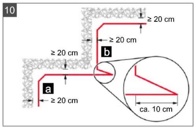
Routing the boundary cable around corners (05, 10)
For inwards going corners (10/a): Route the boundary cable diagonally to avoid the appliance becoming caught in the corner.
For outside corners with obstacles (10/b): Route the boundary cable in a point in order to avoid a collision of the appliance with the corner.
For outside corners without obstacles(05/j): Route the boundary cable at an angle of 90^ .
4.5.4 Enclosing corridors (05/h)
In the corridor the following distances must be complied with:
Total width: min. 60 cm
Distance of the boundary cable to the edge: 20 cm
Distance between the boundary cables: min. 20 cm
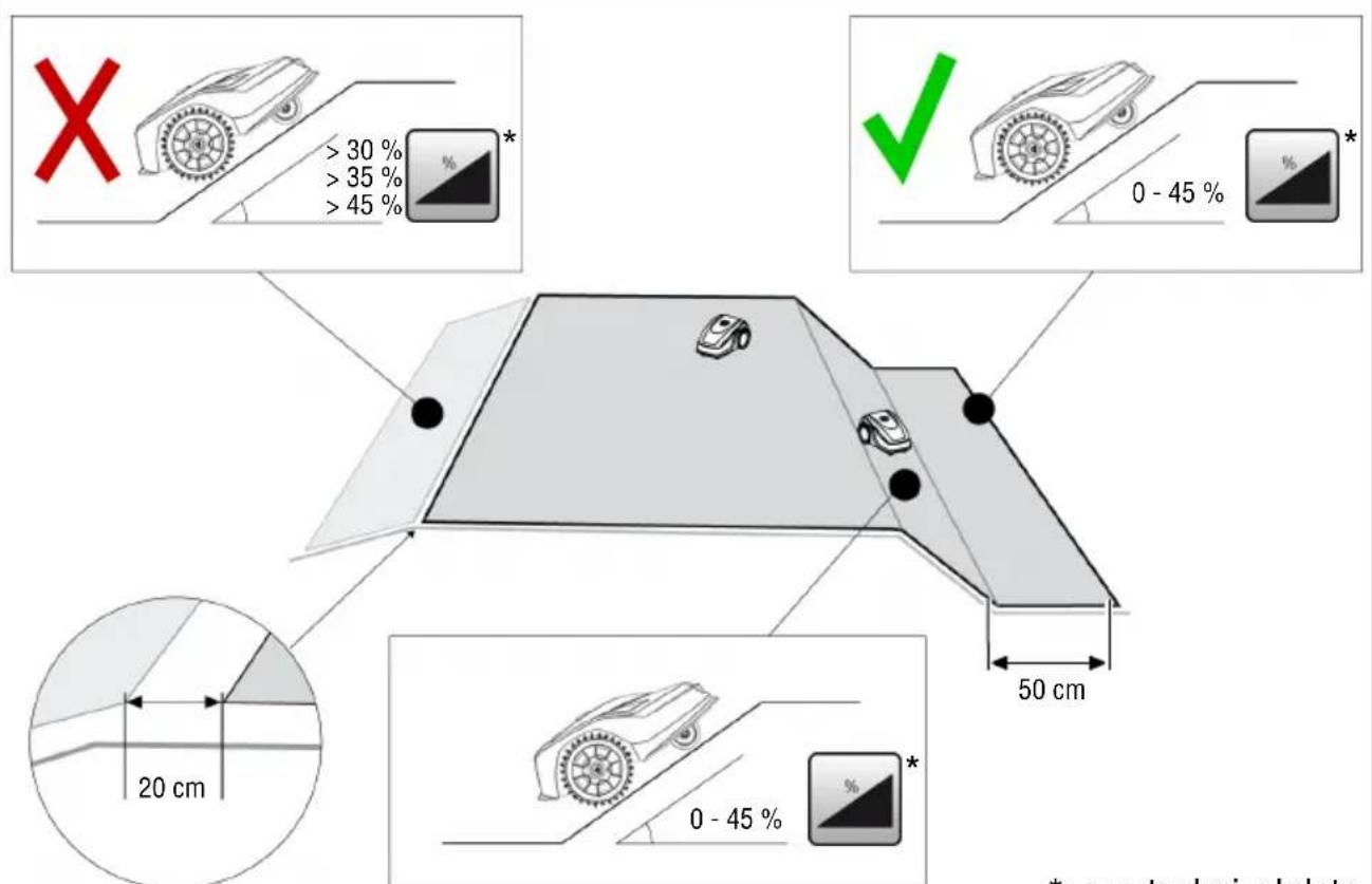
4.5.5 Excluding downward slopes (15)
Downward slopes that are greater than the values specified in the technical data must be excluded with the boundary cable (45% = 45 cm downward slopes per 1 horizontally) (see technical data).
The boundary cable must not be laid over a gradient of more than 20% . In order to avoid problems when turning, maintain a distance of 50 cm to the 20% gradient. If the gradient at the outer edge of the working area is more than 20% at any point, lay the boundary cable on the flat ground at a distance of 20 cm from the start of the gradient.
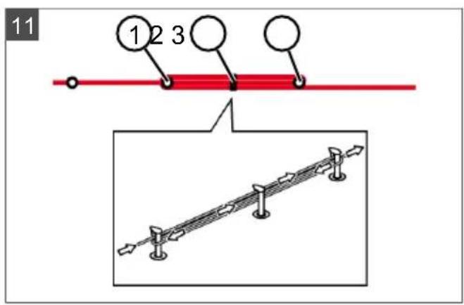
4.5.6 Creating loops of cable (11)
Spare loops of cable should be incorporated at regular intervals in order to reposition the base station or to extend the mowing area even after the mowing area has been laid out.
Select the number of spare cable loops according to your own judgement.
- Lead the boundary cable around the current lawn peg (11/1) and then back to the previous lawn peg (11/3).
- Then lead the boundary cable to the current lawn peg again. This creates a loop. The cables must be close together.
- If necessary, attach the loop to the ground in the middle with an additional lawn peg (11/2).
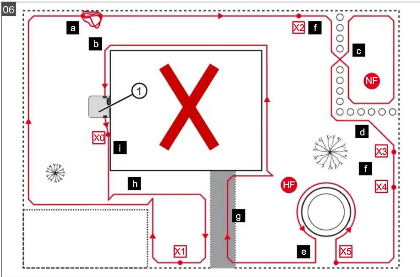
4.5.7 Typical faults in cable routing (06)
- Spare cable loops of the boundary cable are not laid in an even, elongated loop (06/a).
The boundary cable is not routed properly around corners (06/b).
The boundary cable is crossed over or not routed clockwise (06/c).
The boundary cable is routed too imprecisely so that edge areas of the grass surface cannot be mowed (06/d).
The boundary cable is not routed lying directly next to itself when guided towards and back from the edge to an obstacle inside the lawn (06/e).
The start points are set too far away from the base station (06/f).
The boundary cable is routed beyond the edge of the grass surface (06 / g)
- When routing the boundary cable, the minimum distance for corridors of 20cm is undercut (06/h).
The boundary cable is routed too close (i.e. at a distance of less than 20~cm ) to obstacles that cannot be driven over (06/i).
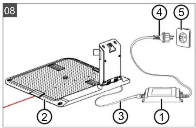
4.6 Connecting the base station to the power source (08)
- Place the power supply unit (08/1) in a dry location that is protected against direct sunlight and sufficiently close to the base station (08/2).
- Screw cable (08/3) firmly onto the power supply unit.
- Plug the mains plug (08/4) of the power supply unit into a power socket (08/5) protected from rain.
NOTE We recommend connecting the power supply to the mains supply via an earth leakage circuit breaker (ELCB) with a rated leakage current < 30mA .
4.7 Checking the connections on the base station (08)
- Check whether the LED on the front side of the charging station (13/1) is lit. If not:
Disconnect the mains plug.
- Check that all plug connectors of the power source and the boundary cable are positioned correctly and check for damage.
Status indications of the LEDs
LED Operating states
Yellow
Lights up if the power source is intact.
4.8 Installing the Quick Homing kit

Scan this QR code to find out how to install the Quick Homing kit. See also installation instructions 443565 "Quick Homing Kit - Installation".
5 START-UP
This chapter describes the activities and settings that are necessary to put the appliance into operation for the first time. For all further settings, refer to see chapter 7 "Settings", page 46.
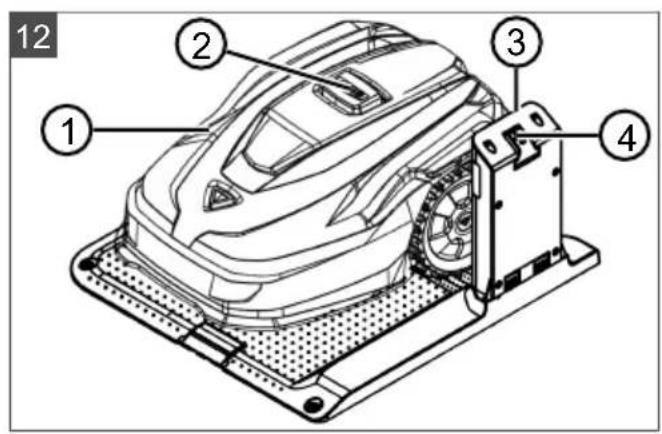
5.1 Charging the rechargeable battery (12)
During normal operation, the battery of the appliance is regularly charged automatically.
NOTE Fully charge the rechargeable battery before using it for the first time. The rechargeable battery can be charged in any charge status. Interrupting charging does not damage the rechargeable battery. The rechargeable battery can only be charged after the appliance has been switched on.
- Place the appliance (12/1) in the base station (12/3) so the contact surfaces of the appliance touch the charging contacts of the base station.
- Switch on the appliance with
- The display on the appliance shows Battery is being recharged. If not: see chapter 10 "Help in case of malfunction", page 50.
5.2 Making the basic settings
- Open the cover flap.
- Switch on the appliance with .mware, code and type are displayed.
- In the menu for language selection, select the language with and accept with
-
In the Login > Enter PIN menu, enter the preset PIN 0000. To do so, select the digit 0 with in sequence and always accept with After entering the PIN, access is enabled.
-
In the Change PIN menu:
Under Enter new PIN, enter a self-selected new four-digit PIN. To do so, select one digit in sequence with and respectively confirm with
Under Reenter new PIN, enter the new PIN again. If both entries are identical, PIN changed is displayed.
- In the Enter date menu, set the current date (format: DD.MM.20YY). To do so, select one digit in sequence with a respectively confirm with
- In the Enter time > HH:MM menu, set the current time (format: HH:MM). To do so, select one digit in sequence with and respectively confirm with
The basic settings have been completed. The Not calibrated Press Start key status is displayed.
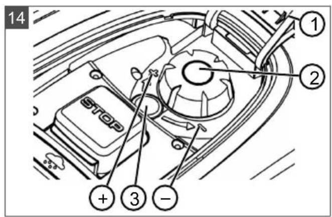
5.3 Setting the cutting height (14)
The cutting height can be manually adjusted continuously between 25 - 55mm
NOTE A cutting height of 55mm is recommended for the calibration movement (see chapter 5.4 "Carrying out an automatic calibration movement", page 45) and for teaching-in the starting points (see chapter 7.5.2 "Setting the start points", page 47).
- Open the cover (14/1).
-
Set the cutting height (the current cutting height is displayed in the window (14/3) in millimetres):
-
Increase the cutting height (i.e. lawn height): Turn the rotary knob (14/2) clockwise (14 / +) .
Decrease the cutting height (i.e. lawn height): Turn the rotary knob (14/2) anticlockwise (14/-).
-
Close the cover.
5.4 Carrying out an automatic calibration movement
NOTE Before commissioning, carry out the calibration movement (see chapter 5.4 "Carrying out an automatic calibration movement", page 45) or teaching-in of the starting points (see chapter 7.5.2 "Setting the start points", page 47).
Place the appliance at the starting position (13)
- Place the appliance at the starting position inside the mowing area:
At least 1 m left and 1 m in front of the base station
- Aligned with the front side to the boundary cable
Starting the calibration movement
- Check that there are no obstacles in the expected movement area of the appliance. The appliance must be able to move over the boundary cable with both front wheels at the same time. If necessary, remove obstacles or lay the cable temporarily inwards (min. 35 cm required).
- Start the appliance with .the following is shown on the display:
!Caution ! Starting Motors
■ Calibration, Phase [1]
During the calibration movement
To determine the signal strength inside the boundary cable, the appliance first moves twice straight beyond the boundary cable and then into the base station and comes to a stop there.
The Calibration completed message is shown on the display.
The rechargeable battery is being charged.
NOTE The appliance must come to a stop when it moves into the base station. If the appliance does not touch the contacts when it moves into the base station, it moves further along the boundary cable. If the appliance moves through the base station, the calibration procedure has failed. In this case, the base station must be better aligned and the calibration procedure repeated.
After the calibration movement
The preset current mowing duration is displayed. For all further settings, refer to see chapter 7 "Settings", page 46.
Robolinho
NOTE To ensure proper operation and reduce error messages, the loop length must be measured using the "Learn entry points" function.
6 OPERATION
6.1 Starting the appliance manually
-
Switch on the appliance with For unscheduled edge mowing: see chapter 7.7 "Edge mowing with a manual start", page 48.
-
Start the appliance manually with
6.2 Cancelling mowing
Press the base station (12/4) or on the appliance.
The appliance moves automatically into the base station. It deletes the mowing plan of the current day and starts again the next day at the set time.
Press the appliance. Mowing is interrupted for half an hour.
Press the appliance. The appliance is switched off.
NOTE In dangerous situations, the appliance can be stopped with the STOP button (12/2).
6.3 Mowing the secondary area (05/NF)
- Lift the appliance and place in the secondary area by hand.
- Switch on the appliance with
- Call up the main menu with
- o* settings
- o* zone mowing
- Select the mowing time with
- Start the appliance manually with
Depending on the setting: The appliance mows for the set time period and then switches off or mows until the rechargeable battery is flat.
After mowing the secondary area, place the appliance in the base station again by hand.
7 SETTINGS
7.1 Calling up the setting - General
- Call up the main menu with Note: The asterisk * in front of the menu item indicates that it has just been selected.
- o* settings
-
Select the required menu item with and accept with
-
Make the settings.
Note: The menu items are described in the following sections.
- Return to the main menu with
NOTE Further menu items: see chapter 5.2 "Making the basic settings", page 44.
- o* kcy clicks
- Activating/deactivating the button tones:
orActivate:Activate the button tones.
or Deactivate: Deactivate the button tones.
7.3 Activating/deactivating Eco mode
In Eco mode, the appliance switches to energy-saving mode. This reduces the energy consumption and noise emissions.
NOTE With high and thick grass and for thick rolled turf, this is not recommended or may not be possible.
- o* Mode
- Activating/deactivating Eco mode:
Activate Activate Eco mode.
Deactivate Deactivate Eco mode.
7.4 Setting the rain sensor
NOTE Mowing when the grass is dry reduces soiling. By activating the rain sensor and setting a delay time, it is possible to prevent the appliance mowing when the grass is wet.
If the rain sensor is activated, the appliance moves back into the base station when the rain begins. It remains there until the rain sensor has dried. Then it waits for the time period that is set as the delay before it continues mowing. The sensitivity of the rain sensor is adjustable.
- on* Rn sensor
- Activating/deactivating the rain sensor:
or Activate: Activate the rain sensor.
or Deactivate: Deactivate the rain sensor.
- Setting the delay of the rain sensor:
or After rain delay
xx hours xx minutes Select the required value for the delay with a accept with .
- Setting the sensitivity of the rain sensor:
or Rain sensitive
Select the required value for the sensitivity with and accept with .
7.5 Setting the mowing program
7.5.1 Setting the mowing program - General
- Call up the main menu with
- oPograms
- Select the menu item with and accept with
- Carry out the settings. Note: The menu items are described in the following sections.
7.5.2 Setting the start points
Teaching-in start points
- Place the appliance in the base station.
- Switch on the appliance with
- Call up the main menu with
- oPwograms
- oEry Point
- o * interactive teach
- start interactive entry point teaching
or start . The appliance moves along the boundary cable.
or set when the appliance has reached the required start point. The start point is stored.
- Set entry point 1 if no start point has been specified during the teaching-in movement. If no start point has been specified here, the start points are automatically specified.
- Entiy point x: XXm if the last start point has been reached.
Manually specifying start points (05)
The first start point (05/X0) is pre-set and is 1 m to right of the base station. Other start points can be defined after this point (see technical data).
When specifying the start points, heed the following:
Select one digit in sequence with and always accept with
- o* Print x2 at [075m]
Select one digit in sequence with and always accept with
- If necessary, specify further start points.
- Return to the main menu with
7.5.3 Setting the mowing times
NOTE There must be at least 30 min. between programming the mowing times and the mowing start. If not, the appliance starts 30 min after the last press of the button at the earliest. In the weekly Program menu item, the days of the week and time periods when the appliance should mow are set. Adapt these settings to the size of your garden if necessary. If unmown areas are still visible after approx. one week, increase the mowing periods.
- or* Weekly Program
or A11 Days [X]: The appliance mows every day at the set times. If A11 Days [] is shown, the appliance only mows on the set days of the week.
or Monday [X]...* Sunday [X]: The appliance mows for the set time periods on the set day of the week. If Monday [ ] is shown, for example, the appliance does not mow on the respective day.
or change:Activate the respective day [X] or deactivate it [ ], and set the time periods, type of mowing and the start points.
- Make the settings for every day or the respective day:
e.g. [M] 07:00-10:00 [?] Normal mowing [M] from 07:00 - 10:00 am with automatically changing start point 0 - 9 [?].
e.g. *[R] 16:00-18:00 [1]: The appliance starts with edge mowing [R] at 4 pm and moves along the entire boundary cable. The area mowing then begins at start point 1 [1]. At 6 pm or as soon as the rechargeable battery is discharged, the appliance moves back to the base station.
or change : Change the selected setting.
or continue: Confirm the changes setting and continue to the next setting.
- Save: Save all changed settings of the menu item.
7.5.4 Passage mode
Passage mode provides for a better mowing result in narrow passages.
- Set the start point in the narrow passage (see section "Setting the start points").
- Start from the set start point in passage mode (see section "Setting the mowing program").
e.g. *[P] 16:00 - 18:00 [3]: The appliance starts at 16:00 h (4.00 p.m.) in passage mode [P] and starts mowing at start point 3 [3]. At 18:00 h (6.00 p.m.) or as soon as the rechargeable battery is discharged, the appliance returns to the base station.
7.6 inTOUCH
An existing connection to a gateway can be disconnected. This means the appliance is ready to establish a new connection for 30 minutes.
NOTE To establish a connection later, the connection must first be disconnected again, even if the appliance was not previously connected with a gateway.

- Reset connection Appliance reports: Done.
- Confirm with and return to the menu.
7.7 Edge mowing with a manual start
For a manual start, the setting can be made here that the appliance begins with edge mowing.
Carrying out the edge mowing at the programmed mowing time periods: see chapter 7.5.3 "Setting the mowing times", page 47.
- o* Margin mowing
- o* a manual start
7.8 Setting the secondary area mowing
- zone mowing
- Setting the mowing time periods:
or nactive: Secondary area mowing is switched off.
- or active : - The appliance mows until the rechargeable battery is flat.
or moving time in min: The appliance mows the secondary area for the set time period. The following mowing time periods can be set: 30/60/90/120/until rechargeable battery flat.
7.9 Setting the display contrast
If the display is difficult to read, e.g. in sunlight, the display can be improved by changing the display contrast.
- play contrast
- Increase/decrease the display contrast with
or and accept with .
7.10 Setting lock
If the setting lock is deactivated, the PIN must only be entered when acknowledging safety-relevant faults.
- o* safety settings
- Activating/deactivating the setting lock:
orActivate:Activate the setting lock.
or Deactivate: Deactivate the setting lock.
7.11 Recalibrating
If the position or length of the boundary cable has been changed or the appliance no longer finds the boundary cable, recalibration is necessary.
- oReset calibration
- Reset loop calibration data?
- Carrying out a calibration movement: see chapter 5.4 "Carrying out an automatic calibration movement", page 45.
7.12 Restoring factory settings
The factory settings of the appliance can be restored, e.g. before selling the appliance.
1. Factory reset Appliance reports:Factory reset completed
The Information menu is used for displaying machine data. No settings can be made in this menu.
- Call up the main menu with
- on formation
-
Select the menu item with and accept with Note: The menu items are described i following sections.
-
Return to the main menu with
Blades service
Shows in how many operating hours a blade service is required. The counter can be reset manually. Have the blade service carried out by an ALKO dealer, technician or service partner.
Reset the counter for blade service:
- conVrm
Hardware
Shows information on the appliance, such as type, year of manufacture, operating hours, serial number, number of mowing operations, total mowing time, number of charging cycles, total charging time, length of the loop of the boundary cable.
Software
Shows the software version.
NOTE Keep the software of the Robolinho automatic lawn mower up to date at all times. Check the firmware version at regular intervals and update it as necessary. The Robolinho updater software can be found on the Internet at: www.al-ko.com/shop/de/robolinho-autoupdater
Program Info
Shows current settings such as the total weekly mowing time.
Failures
Shows the fault messages that last occurred with date, time and fault code.
9 MAINTENANCE AND CARE
CAUTION! Risk of injury. Sharp-edged and moving appliance parts can lead to injury.
Always wear protective gloves during maintenance, care and cleaning work!
9.1 Cleaning
IMPORTANT! Danger from water. Water in the automatic lawn mower and in the base station leads to damage on electrical components.
- Do not spray the automatic lawn mower and base station with water.
Clean the automatic lawn mower
CAUTION! Danger of injury due to the
cutting blade. The cutting blades are very sharp and can cause cutting injuries.
Wear protective gloves.
Make sure that parts of the body do not get into the cutting blade.
Once a week, carry out the following:
- Switch off the appliance with
- Wipe off the surface of the housing with a broom, a brush, a damp cloth or a fine sponge.
- Brush off the underside, mower deck and cutting blade with a brush.
- Check the cutting blade for damage. If necessary, replace the following: see chapter 9.3 "Replacing the cutting blades", page 50.
Cleaning the base station
- Regularly remove grass residues and leaves or other objects out of the base station.
- Wipe off the surface of the base station with a damp cloth or a fine sponge.
9.2 Regular checks
General check
- Once a week, check the whole installation for damage:
Device
Base station
Boundary cable
Power supply unit
- Replace defective parts with original spare parts from the manufacturer or have them replaced by one of the manufacturer's service centres.
Check the rollers can move freely
Once a week, carry out the following:
- Carefully remove grass residues and soiling from the areas around the rollers. using a hand brush and cloth.
- Check that the rollers run freely and that they can be steered.
Note: If the rollers do not move freely or cannot be steered, have them replaced by one of the manufacturer's service centres.
- Use a cloth to remove soiling and then lightly grease with contact grease.
- Disconnect the mains plug.
- Press the charging contacts in the direction of the base station and release them. The charging contacts must spring back into the initial position.
Note: If the charging contacts do not spring back, have them replaced by one of the manufacturer's service centres.
9.3 Replacing the cutting blades
CAUTION! Danger of injury due to the cutting blade. The cutting blades are very sharp and can cause cutting injuries.
Wear protective gloves.
Make sure that parts of the body do not get into the cutting blade.
IMPORTANT! Damage to the appliance due to incorrect repair. The blade plate can be damaged by the alignment of a bent, built-in cutting blade.
Do not straighten bent cutting blades.
Replace bent cutting blades with original spare parts from the manufacturer.
Worn or bent cutting blades must be replaced.
- Switch off the appliance with
- Set down the appliance with the cutting blades facing upwards.
- Unscrew the fastening screws.
-
Take the cutting blade out of the blade seat.
-
Clean the blade seat with a soft brush.
Note: The cutting blades are sharpened over the entire length and can therefore also be mounted rotated by 180^ , which doubles their service life.
- Replacing the cutting blades:
If cutting blades have not been rotated since the initial mounting: Rotate the cutting blades by 180^ and insert into the blade seat again with the sharpened side pointing towards the appliance, and tighten the fastening screws again by hand.
If the cutting blades have already been rotated once since the initial mounting: Insert new cutting blades into the blade seat again with the sharpened side pointing towards the appliance, and tighten the new fastening screws by hand.
Note: It is only allowed to use original spare parts of the manufacturer.
In case of stubborn dirt that cannot be removed with a brush, the blade plate must be replaced because an imbalance can lead to higher noise levels, increased wear and malfunctions.
As a rule, the clearer blades do not need to be replaced.
10 HELP IN CASE OF MALFUNCTION
10.1 Correcting appliance and handling faults
CAUTION! Risk of injury. Sharp-edged and moving appliance parts can lead to injury.
Always wear protective gloves during maintenance, care and cleaning work!
NOTE For malfunctions that are not listed in this table or that you cannot resolve yourself, please contact our customer service.
Appliance does not start.
Battery is flat. Charge the appliance in the base station.
| Malfunc-tion | Cause Remedy | |
| The appliance gets stuck and has dug itself in. The wheels continue to turn. |
| ■Bump sensors do not trip. Contact one of the manufacturer's service cen-tres. |
| ■The grass is too high. | ■Increase the cutting height, then lower in steps to the required height.Mow the grass short with a lawn mower. |
| ■The appliance snags on an un-evenness of the grass surface. | Eliminate the unevenness. |
| The appliance mows at the wrong time. |
| ■The appliance has the wrong time. | Set the correct time. |
| ■The mowing duration is incorrectly set. | Set the mowing times correctly. |
| ■The appliance loses the time set-tings. | Battery is defective. Contact one of the manu-facturer's service centres. |
| Motor stops during mowing. |
| ■Motor is overloaded. Switch off the appliance, set down on level ground or shorter grass and restart. |
| ■Battery is flat. Charge the battery. |
| ■The cutting blades are blunt. Turn over or replace cutting blades if necessary. |
| Mowing result is uneven. |
| ■Mowing time is too short. Program longer mowing times. |
| ■Mowing area is too large. Reduce the mowing area. |
| ■Cutting height is set too low. Increase the cutting height, then lower in steps to the required height. |
| ■The cutting blades are blunt. Turn over or replace cutting blades if necessary. |
| Battery operating time drops significantly. |
| ■Cutting height is set too low. Increase the cutting height, then lower in steps to the required height. |
| ■Grass is too long or too wet. | ■Allow the grass to dry.Set the cutting height to a higher level. |
| Appliance vibrates or the volume is too high. |
| Imbalance on the cutting blade or in the cutting blade drive | ■Clean the mower deck.Contact one of the manufacturer's service centres. |
| Rechargeable battery cannot be charged or low battery voltage |
| The charging contacts of the base station are soiled.The contact surfaces on the appli-ance are soiled. | Clean the charging contacts and contact surfac-es. |
| Base station has no power. Connect the base station to the power source. | |
| The appliance does not touch the charging contacts. | Place the appliance in the base station and check that the charging contacts make con-tact.Contact one of the manufacturer's service centres. |
| The service life of the battery has expired. | Contact one of the manufacturer's service cen-tres. |
| The charging electronics are faulty. | Contact one of the manufacturer's service cen-tres. |
10.2 Fault codes and troubleshooting
NOTE For malfunctions that are not listed in this table or that you cannot resolve yourself, please contact our customer service.
| Error code Cause Remedy | | |
| CN001: Tilt sensor The tilt sensor has tripped:Max. tilt angle exceededThe appliance has been carriedSlope too steep | Place the appliance on a flat surface and cancel the fault. | |
| CN002: Lift sensor The lift sensor has tripped:The appliance cover has been deflected upwards by lifting or by an obsta-cle. | Remove the obstacle. | |
| CN005: Bumper de-flictedThe appliance has collided with an obstacle and cannot free itself (e.g. collision close to the base station). | Place the appliance on the free, de-marcated lawn surface.Correct the position of the boundary cable. | |
| CN007: No loop sig-nalThe boundary cable is defective.Loop signal is too weak. | Check the LED on the base station.Check the power supply to the base station. Disconnect and reconnect the power supply unit.Check the boundary cable for dam-age. Repair the defective cable. | |
| Error code Cause Remedy | |
| CN008: Loop signal weak | Loop signal too weakBoundary cable buried too deep | Check the LED on the base station. Check the power supply to the base station. Disconnect and reconnect the power supply unitRaise the boundary cable to the prescribed height; attach directly to the lawn, if necessary. |
| CN010: Bad position | The appliance is outside the demarcated lawn surface.The boundary cable has been routed in a criss-cross pattern. | Place the appliance on the free, demarcated lawn surface.Correct the position of the boundary cable around curves and obstacles Eliminate the criss-crossing of the cable. |
| CN011: Escaped robot | The appliance is outside the demarcated lawn surface. | Correct the position of the boundary cable around curves and obstacles. |
| CN012: Cal: no loop | Error during calibration:The appliance cannot find the boundary cable. | Check the power supply to the base station. Disconnect and reconnect the power supply unit. Place the appliance in the pre-scribed calibrating position; align precisely at right angles. Appliance must be able to drive over the boundary cable. |
| CN015: Cal: outside |
| CN017: Cal: signal weak | Error during calibration:Loop signal too weakNo loop signalThe boundary cable is defective. | Place the appliance in the pre-scribed calibrating position; align precisely at right angles. Check the power supply to the base station. Disconnect and reconnect the power supply unit. Check the boundary cable for damage. |
| CN018: Cal: collision | Error during calibration:The appliance has collied with an obstacle. | Remove the obstacle. |
| CN038: Battery The battery is flat: | |
| Loop of the boundary cable is too long, too many islands. | Correct the position of the boundary cable. |
| No contact with the charging contacts during charging | Clean the charging contacts. Place the appliance in the base station and check that the charging contacts make contact.Have the charging contacts checked and replaced by one of the manufacturer's service centres. |
| Error code Cause Remedy | | |
| ■ Obstacles close to the base station | Remove the obstacles. |
| ■ The appliance has got stuck. | Place the appliance on the free, demarcated lawn surface. |
| ■ The appliance does not find the base station. | ■ Check the boundary cable for damage.
■ Have the boundary cable repaired by one of the manufacturer's service centres. |
| ■ The battery is flat. Have the battery replaced by one of the manufacturer's service centres. | |
| ■ The charging electronics are faulty. | Have the charging electronics checked by one of the manufacturer's service centres. |
| CN099: Recov escape | Automatic fault rectification not possible | ■ Manually acknowledge the error message.
■ If the fault occurs again: Have the appliance checked by one of the manufacturer's service centres. |
| CN104: Battery overheating | ■ Battery has overheated (more than 60°C). Dis-charging is not possible.
■ Emergency switch-off by monitoring electronics | ■ Switch off the appliance and allow the battery to cool down.
■ Do not place the appliance on the base station. |
| CN110: Blade motor over heating | Mowing motor has overheated (more than 80°C). | ■ Switch off the appliance and allow it to cool down.
■ If the fault occurs again: Have the appliance checked by one of the manufacturer's service centres. |
| CN119: R-Bumper deflected | The appliance has collided with an obstacle and cannot free itself. | Remove the obstacle. |
| CN120: L-Bumper deflected | | |
| CN128: Recov Impossible | ■ The appliance has collided with an obstacle and cannot free itself. | Remove the obstacle. |
| ■ The appliance is outside the demarcated lawn surface. | ■ Place the appliance on the free, demarcated lawn surface.
■ Correct the position of the boundary cable. |
| CN129: Locked WL Left wheel motor is blocked. Remove the blockage. |
| CN130: Locked WR Right wheel motor is blocked. | Remove the blockage. |
The description of other error codes can be found on the AL-KO homepage.
11 TRANSPORT
To transport the appliance, proceed as follows:
- Stop the appliance with ton.
the stop but
- Switch off the appliance with

- Lift the appliance with both hands on the housing:
Do not touch the cutting blades.
The cutting blades must always point away from the body.
12 STORAGE
12.1 Storing the automatic lawn mower
The appliance must be stored over winter or when it is to be taken out of service for an expected duration of longer than 30 days.
- Fully charge the rechargeable battery (Charging the rechargeable battery (08))
- Thoroughly clean the spreader (see chapter 9.1 "Cleaning", page 49).
- Store the appliance:
upright on all wheels
in a dry, lockable location protected from frost
out of the reach of children
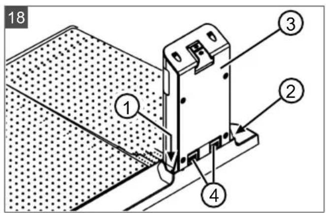
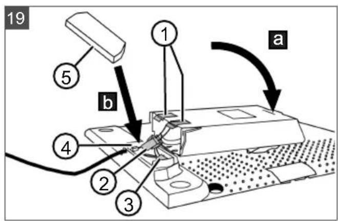
12.2 Dismantling and storing the charging pole (18, 19)
Dismantle and store the charging pole over the winter or when it is expected to be out of service for a period of more than 30 days.
- Disconnect the power supply unit from the mains supply and unplug from the base station.
- Removing the charging pole:
Unscrew the two screws (18/1) and (18/2) of the charging pole (18/3).
Press the two buttons (18/4, 19/1) at the same time to release the charging pole.
Tilt the charging pole (19/a).
- Disconnect plug connectors (19/2) and (19/3).
- Close (19/b) the opening in the base (19/4) with the winter cover (19/5), see Technical data.
- Storing the charging pole:
in a dry, lockable location protected from frost
out of the reach of children
12.3 Winter storage of the boundary cable
The boundary cable can remain in the ground and does not need to be removed.
13 DISPOSAL

Electrical and electronic appliances do not belong in household waste, but should be collected and disposed of separately!
Used batteries or rechargeable batteries that are not installed permanently in the old appliance must be removed before disposal. Their disposal is regulated by the battery law.
- Owners or users of electrical and electronic appliances are obliged by law to return them after use.
The end user bears personal responsibility for deleting his personal data from the old appliance to be disposed of.
The symbol of the crossed-through rubbish bin means that electrical and electronic appliances may not be disposed of in the household rubbish. Electrical and electronic appliances can be handed in at the following places at no charge:
Public service disposal or collection points (e.g. municipal building yards)
Points of sale of electrical appliances (stationary and online) if dealers are obliged to take them back or offer this voluntarily.
These statements only apply to appliances that are installed and sold in the countries of the European Union and are subject to European Directive 2012/19/EU. Different provisions may apply to the disposal of electrical and electronic appliances in countries outside the European Union.

Used batteries and rechargeable batteries do not belong in household waste, but should be collected and disposed of separately.
For safe removal of batteries or rechargeable batteries from the electrical appliance and for
information on their type or chemical system, follow the further information within the operating or installation instructions.
- Owners or users of batteries and rechargeable batteries are obliged by law to return them after use. Return is limited to the handover of customary household quantities.
Used batteries can contain harmful substances or heavy metals that can cause damage to the environment and human health. Reuse of the used batteries and use of the resources contained therein contributes to the protection of these two essential commodities.
The symbol of the crossed-through rubbish bin means that batteries and rechargeable batteries may not be disposed of in household rubbish.
In addition, if the symbol Hg, Cd or Pb appears under the rubbish bin, this stands for the following:
Hg: Battery contains more than 0.0005% mercury
Cd: Battery contains more than 0.002% cadmium
Pb: Battery contains more than 0.004% lead
Rechargeable batteries and batteries can be handed in at the following places at no charge:
Public service disposal or collection points (e.g. municipal building yards)
Points of sale of batteries and rechargeable batteries
Disposal points of the common take-back system for the used batteries of appliances
- Disposal point of the manufacturer (if not a member of the common take-back system)
We hereby declare, as the exclusively responsible party, that this product in its marketed form
These statements apply only to rechargeable batteries and batteries that are sold in the countries of the European Union and that are subject to European Directive 2006/66/EU. Different provisions can apply to the disposal of rechargeable batteries and batteries in countries outside the European Union.
The packaging materials are recyclable. Please dispose of packaging in an environmentally friendly manner.
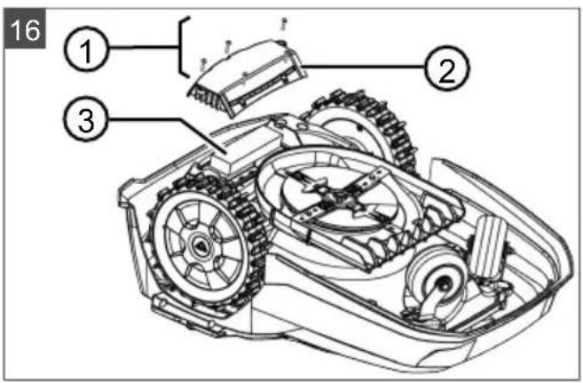
Removing the rechargeable battery before disposing of the appliance (16)
The integrated rechargeable battery must be removed before disposal of the appliance and disposed of separately in an environmentally friendly manner.
- Undo the screws (16/ 1).
- Take off the cover of the rechargeable battery compartment (16/2).
- Unplug the rechargeable battery (16/ 3) and take it out.
- Put the cover back on and fasten the screws.
14 AFTER-SALES/SERVICE
In the event of questions of warranty, repair or spare parts, please contact your nearest AL-KO Service Centre. These can be found on the Internet at: www.alko-garden.com/service-contacts
Further information on spare parts can be found at:
www.alko-garden.com/spareparts
meets the requirements of the harmonised EU Directives, EU safety standards and the product-specific standards. The Declaration of Conformity forms part of the operating instructions and is included with the machine.
16 WARRANTY
We will remedy any material or manufacturing defects discovered in the device during the statutory period of limitation for claims for defects by repair or replacement at our discretion. The period of limitation is determined in each case by the law of the country in which the device was purchased.
Our warranty promise applies only if:
These operating instructions are observed
The device is handled correctly
Original spare parts have been used
The warranty becomes void in the case of:
Unauthorised repair attempts
Unauthorised technical modifications
Use for other than the intended purpose
The warranty does not include:
Paint damage attributable to normal wear
Wear parts that are marked with a box xxxxx (x) on the spare parts card
The warranty period commences with the purchase by the first end user. The date on the proof of purchase is decisive. In the event of a warranty claim, please contact your dealer or the nearest authorised customer service centre with this declaration and the original proof of purchase. This declaration does not affect the purchaser's statutory claims for defects against the vendor.
VERTALING VAN DE ORIGINELE GEBRUIKERSHANDLEIDING
Inhoudsopgave
2 PRODUCTOMSCHRIJVING
2.2 Robot-grasmaier (02)
Nr. Component
Robot-grasmaier reinigen
!Caution ! Starting Motors
- Calibration, Phase [1]
Med kalibracijski voznjo
!Caution ! Starting Motors
■ Calibration, Phase [1]
- i# Entry Point
- iint x1 at [020m]
Koristeci uzastopce odaberite brojku i preuzmite koristeci
- i Point x2 at [075m] Koristeci uzstopce odaberite brojku i preuzmite koristeci
- Po potrebi odredite dodatne poctne tocke.
- Vratite se na glavni izbornik koristeči.
- it+ Margin mowing
- it* manual start
He Bo3nte ce Haypehajy!
2.4 KomaHDo noJIbe (03)
Bp. CactabHn Deo
1
(TacTeP Home):пекинту реким Кош�ьа,уpeйсce враhaу 6а3Hy CTанич.СлdeHERдэна ce onet NOKpehe ayTomatcki y NOdeшeHo BpeMe KОш�ьa.
2 Cen3op 3a Knuy: Pernctpyje da Jn nada Knua (Bnuu Nooaabe 7.4 "Poeaaabe ceH3opa 3a Kuuy", cmpaHa 194).
3Диспгел:Пика3уjeТрeHyTHo padHo cTaHbe ypehaja,Ha3nB n3a6paHor MeHnja,HeRoBe CTaBKe MeHnja,Kao n n36OpФyHKuJa(BuDn IToaJaEbe 2.5 "Ducnepf",cmpaHa 183).
4
Tactepn ca ctpenlaMa):
BpaBe CTaBN MeHna, NObeHaBaHe n CmaHbNAbe 6pojuaHx BpeHocTH,
BpaBe N3MeHy NoeShaBaHa.
Бр.СаТВнДeo
5

(Tactep cTapt/nay3a):
PnTncHyTu jeaHnyr:PyuHo nokpeHnte i npekuajTe pekum KOseHa.
PnTnCHytn Dba nyTa: Odmax HacTabte peXm KoWeHa nocJe npTnCKaHa TaCTepa Home.
6

(ФункиjsckTacTepeN):
P03BaTnФyHKunjy,koja ce ynpaBo npka3yje n3Haad Tactepa Ha dncnnejy.
7

(TacTeP On/Off): YKbUyHBaHe n ByuHaBe ypehaja.
8

(TaTeP 3a MeHn): POKpeTaHbeB, BHOr MeHnJa.
2.5 Ducnnej
Бр. ИndиKaTOp
1 Ha3nB n3a6paHOr MeHnJa (OBd: Main Menu)
2 CTabKe MeHnja y MeHnju: YBeK ce npika3yj caMo DBe CTabKe MeHnja (OBd: Settings n Information).

Môvôhe je πρικα3aTN
ДоаТсtabkeMeHja.
3Функиjee 3a n3a6paHn cTaNky MeHnja
(ОБе: Settings).Са

Moryhe je no3BaTu cyHKuJe.
4 3Be3dNue 3a 03NaUaBaIbe npKka3aHe CTaBKe MeHnJa (OBne: Settings)
2.6 CtpyKTypa MeHnja
Main Menu
Programs
Weekly Program BvIe 7.5 "PoeaAbe npoepama KoWeBa", cmpaHa 194
Entry Point BvI NpOaBBe 7.5.2 "Nodeuaeae neouemhux maoka", cmpaHa 194
Program Info BnI NooaBe 8 "Ppuka3 uHfopMauju", cmpHa 196
Settings
Time BnDn NooaBbe 5.2 "Ppey3umae ochoeHX nodeaaaba", cmpaHa 191
Date BnDn Np2naBbe 5.2 "Ppey3umHe ochoBHX nodeaaba", cmpaHa 191
Language BnI NpOaBBe 5.2 "Ppey3umbe ochoeHux nodeuaaba", cmpaHa 191
PIN-Code BnI IopaaBe 5.2 "Ipey3umbe ochoBHX nodeaaba",
cmpana 191
Key clicks Bvndn Po2naBbe 7.2 "Akmueupahe/deakmueupahe 36ykoea macmepa", cmpaHa 193
EcoMode BvDn NooJaBbe 7.3 "Akmueupahe/deakmuaebe Eco pekuma pada",cmpaHa 193
Quick Homing Kit BUDI NsnaBbe 4.8 "HcmaaJka Komnema Quick Homing Kit", cmpaHa 191
Rain sensor BvDn Pioaaebe 7.4 "Podeuaebe ceH3opa 3a Kuuy", cmpaHa 194
After rain delay BvDn POnaBbe 7.4 "POneWaaBaHe cEH3opa 3a KuwY",cmpaHa 194
Rain sensitive BvDn POnaBBe 7.4 "POneWaaBHe ceH30pa 3a KuWy", cmpaHa 194
inTOUCH BnuI NooJIaBJIe 7.6 "iINTOUCH", cmpHa 195
Margin mowing BvDn PoiJaaBbe 7.7 "KoWeHBe Ueua npu pyHOM nokpemaHy", cmpaHa 195
Sub zone active/disabled BnI NpOaJIbe 7.8 "NpOeUaBaHe KooeHa cnpedHux noepuHa", cmpaHa 196
Display contrast Bündi Noelanaebe 7.9 "Nodewaahe KOHmpacma ducnpeja", cmpaHa 196
Safety settings BvNi PoiJaIe 7.10 "3aumma nodewaaba", cmpaHa 196
Reset calibration BvDn PoJae7.11 "POnOBHa KaIubpaUja", cmpaHa 196
Factory reset BUDI NoaJIe 7.12 "PecemoeaHe Ha pa6puka nodeuaaHa", cmpaHa 196
Blades service BnDn POnaBBe 8 "PpuKa3 uHΦopMaujuA", cmpaHa 196
Hardware BnI N O2JIa8JIe 8 "PpKa3 uHΦopMauJua", cmpHa 196
Software BnI NpOaJIe 8 "PpuKa3 uHΦopMauJua", cmpaHa 196
Program Info BvIe IooaBe 8 "Ppuka3 uHcOpMauju", cmpaHa 196
Failures BnI Np2a8Be 8 "Ppka3 uHΦopMauja",cmpaHa 196
2.7 Ba3Ha cTaHua (04)
| Бр. Састовни.Deо |
| 1 Дова пioча |
| 2 Лев за п riпka3 статуca |
| 3 Контакл за пьveиbe |
| 4 Тасер Home |
| 5 Стуб за пуьeиbe |
| 6 Кабловско okно |
Bp. CactabHn Deo
7ydy6beHeBe 3a Toayak
8 OToBop 3a Bnjke 3a 3emBy (9)
9Buiu3a3eMby
- 3aBnCHO OJ MoJeNa (BnDn TexHnUke NoDaTKe)
2.8Батурда
KopncnK MoKe Da npomeHn 6aTeepnyj.
HANOMEHA Do Kpaja HanyHnTe
akymynapop nppe npBe ynoTpe6e. Akymynapot ce MoKe nyHnTu Ha 6nNo Kojem HnBOy HanuheHOCTn. IpeKnDaHe NyHeBa He uTeTn akymynapoty. Akymynapot MoKe da ce nyHn camo KaJa je ypehaj yKbUyeH.
Akymyataop je DeiHmNHO HanhybeH npnIKOM nCnpuyke. Y HopMaHHom peKIMy paDa ce akymyataop peDobHO nyH.N T cy CBpxy ce ypehaj nomepa y 6a3Hy cTaHnU.
IHTerpicaHa eNeKtpOnHka 3a Ha3Op ayTomatcKn 3ayCTaBbA nyBeHe KaDa ce DocerHe cTaTyc NyBeBa od 100%
Ipouec nybeba cyHKnOHNwe caMo aKO cy KOHTaKTn 3a NybeBe 6a3He cTaHnue y 6ecnPekOPHom KOHaTKTy ca DoOpHm NOBpUnHaMa ypehaja.
Ha TempepaTpaMa n3HaD 45 ^ C yrpaJeha 3aHTtA cKnONka cnpeyaba nyBeHe aKymylaTopa. Ha Taj NaHn ce n36eraba pa3apaBe aKymylaTopa.
Ako ce bpe me pada akymylaTopa ynpkoc TOME ITO je MaKcImaJIHO HanyBHeN 3HaTHO cKpaTI, Tpe6a 3aMeHHTn cam akymylaTOp.
Ako ce akymylaTop 360r CTapeBa nI npdeytor cknadnWTeBa nCnpa3Hn nCnoD npara Koju je odpeDnO npOn3BOhau, Bnue ce He moKe nyHtN. PpOBepnte akymylaTop n eJektpoHnky 3a NaD3Op KOd nInCTpn6yTepa, TexnUapa nIi cepBnCHor napThepa KOMnAnJe AL-KO n 3amEnTe nx no notpe6n.
Ctatyc akymyntopaje npka3an Ha dincnpejy. PpOBepTu CTatyc akymyntopao nocne oko 3 meceua cknaiunTeHa. Y ty CBpxy ykbuyHTuyehaj n OCHiTATn CTatyc akymyntopao. Ako je akymyntop HanybeHa camo oko 30% , CTaBNTe ypehaj y 6a3Hy cTahnuy u kbluyte ra da 6nCTe nyHnIy akymyntop. Ako je cTy6 3a nphepe radnycknaDNIuTEbA CKNHT ca 6a3He cTahnue (BNDI PoanaeBe 12.2 "DemohmaKa u cKladuimebe cmbya 3a nphebe (18, 19)," cmpaHa 203), npBO ra noHOBO MOHTnpajTe obpHyTM peOcneDom I NOHOBO npNKlbuyTe 6a3Hy cTahnUHa eNeKTpnHy Mpexky.
Ako je doшно do cylpeha eeneKtpoNIta y nperpadi 3a 6atepnjy:JaTe ypehaj Ha nonpaBky cepBnc fnpme AL-KO!
Ako je akymylaTop demoHTnpaH n3 ypehaja: Ako cy oyni npye douJe y KOhtaK T ca
IcUpeJIIM eIeKTPoJNTOM, OdMax IcNepuTe BOJOM. OdMax NotpaxKeIe Nekapa!
2.9 Onnc yHKnje
KpeTaBe no TpaBHaToj nobpunHn
Ypehajce cno6oJHO Kpehye noDpyjy KoWeHa koje je odpeheNo rpaHnHm Ka6nom.
Opjuentaujya ypehaja ce Bpun npeko ceh3opa kojn deTeKtyjyeKeKtpomarHeTHO NOBe rpaHnUHor ka6na.
Ako ypehaj ydapn o npenpeky, 3ayctabba ce n HacTabba y dpyrom cmepy. Ako ypehaj dohe y CNTyaunjy y kojo pad Hnje moryh, Ha dincnnejy ce npka3yje nopuka.
Ako ypehaj npu yKbyuHOM ceH3opy 3a Knuy npen03haje Bnary, ayTomatckn ce Bpaha y 6a3Hy cTaHnUy.
Pexm KoWeBa n pexm nyBeBa
Φa3e KoWeBa ce CtaIHO CMeHbJy ca φa3ama NyHeBa. Ako ce HanyBeHocT aKymyIaTopa cMaHnIo Ha oDpeHey BpeHocT npNJIKOM KoWeBa (pNka3: 0%), ypehaj ce BpaHa y 6a3Hy cTaHnUy Dux rpaHnUHe KInCe.
Iporpamn 3a KoWeHe cy yHa nped noDeWeHn mOry ce doaTHo nOeWabatn Ha ypehajy nn y anNkauj.
CbaN nyT kaJa ce MOTOp KocnIuCe NOKpeHe, MeBa Ce HBeRoB CMeP potaunje, wTO yDBOCTpyUye BEK TpaJHa HOKeBA.
2.10 MoDyI KojI ce noBe3yje nyTem WiFi-ja Smart anJnkauJa AL-KO inTOUCH Smart Garden
Pobotka kocnna opembeH je paio Moynom koJc ne nobE3yje nyTem WiFi-ja.Obaj moen omOryhye Iako ynpabbahe, NdewaBe n Hnd3npaBe npeKo anJaKaunje Ha HeKOM MObHOM ypehajy (nameTHn Telepon, Tabnet).
HANOMEHA 3a Kopushhebe Mo6nHorypehaja nytem annkaunej AL-KO inTOUCH Smart Garden HeonxodHa je Be3a ca INHTepHETOM.
HANOMEHA Da 6n coΦTBep 3a po6o3cky Kocnniuy yBek 6no axkpnpaHa HajHObiny Bep3ny, Mopa da 6yde noBe3an ca INTEpHEtOM npeKo WiFi mpexe. Annkaunja AL-KO inTOUCH Smart Garden obabeuTaba KaDa ce nojabe HOBe Bep3nje coΦTBepa 3a po6oTCKy Kocnniuy. OHe ce ayTomatcKn npey3majy ca INTEpHeTa.
Anlkauna AL-KO inTOUCH Smart Garden
AnlkaJa AL-KO inTOUCH Smart Garden je DocTyHa 3a ypehaje Ha 6a3n Android-a y Google Play Store-y n 3a ypehaje Ha 6a3n iOS-a y Apple App Store-y:


Available on the
App Store

GET IT ON
Google Play
CkeHnpajTe OBaj QR KOJ, da 6ncTe ca3HaJI NaKo Da INcTaInpaTe anNkaunjy AL-KO inTOUCH Smart Garden Ha BaWem NametHom Tepeohny I doBnjeTe DoaThe IHOpmaunje O BaWemypehajy. C TIm MoKeTe Da Baw smart-connected ypehaj TaKoHe NobExeTe Ca INTepHETOM.
HANOMEHA Po6oTcka kocniluca ce
nckbvyno nobezyje ca WiFi mpekom od
2,4 GHz. He noopxabajy ce WiFi mpexe oD
5 GHz.
Да 6и ce Baша роботcka косипа koja ce може
новezиВати пеко Wi-Fi-ja noBE3ana ca
анлікагиом AL-KO inTOUCH Smart Garden,
робOTсka косипа иnametни телфон морajу
да се habазе у дOMeTy Wi-Fi pyTepa ca
дОвOBьHOM jaЧИHOM сИнHLa (пpenopyka:
Min. 50%).
-
Покренте anecdikaшиу AL- KO inTOUCH Smart Garden.
-
JeHOKpaTHO KpeuPaHe KopnCHNuKor HAnora:
KnKKHnte Ha "PpnaJbNbBaBe /
Pernctpaunja">"Pernctpaunja".
UheCte nmejI aDpecy I No3nHky.
AknBupajTe noBe "PpOHTao/na n carJaacn/Ha cam...
IodnHnte Tactep "Perncpaunja".
- Пиравпесnomohу noctojeher KOpICHnKor Hanora.
4.ДоирИВаьем"Долaj HOвуypeй" NOKpeHnte acNCTeHTa 3a NOBe3ИВаьe.
5.Cneintn daIba ynytCTBa.
HANOMEHA YkoNko ce po6oTcKa
Kocnna Kpehe y deNy bawte ca nowom WiFi Be3OM nnn 6e3 He, noDeewabaBa annkaunje AL-KO inTOUCH Smart Garden ce Bpwe Tek NowTo ce poobotcka Kocnna BpaTu y Deo 6aWTe ca do6pim WiFi cnHaIOM. Ako Wi-Fi cnHapyTepa y ueoj bawtn Hnje DoBOJbHo jaK, HerOB domet MoKe Da ce npwnrp yobuaJeHm peNETTOPOM.
Y cnyajy fynknohaHnX CMeTbN, MoKe Bam Nomoh npodabaKoJn IMa nHctaInpaHy anIIkaunjy AL-KO inTOUCH Smart Garden.
IpoaBcy ce npeko annkaunje AL-KO inTOUCH Smart Garden mopa omoryhntn daBnHcKn npncTy npo6tckoj kocnniu.
OcHMaJIbHckOr npIcTypa CBIM NOBe3aHIM
poBOTCKM KocnUcaMa,Smart anNkauJa ALKO inTOUCH Smart Garden Hyn dpyre
fYHKuJe, nonyT noBe3nBaHe ca dpyrIM AL-KO
yehajima,nyH HOtnΦnKaunje y cnyajy
rpewke.
3BE3BEdHOCT
3.1 CbpcncxOHa ynoTpe6a
Obaj ypehaj je npedBnH en NCKbUyHBO 3a npnbatHy ynotpe6y. Cbakn dpyraunn HauHH Kopuheba, kao n Heo3BOJbe He npenpaBke nn DOrpaIHe ce cMaTpa HeHaMeHcKOM yNotpe6om n DOBoOn Do pectaKa BaeHeRa rapanuJe, r6ntka ycarnaWeHoCTn ca nponncmna n OdbjaBa cBAke OndroBOPHOCTn npon3BOJaHa 3a wTeTy KOpNCnKa nIn TpeHnx Niua.
Гразице пиме He ypehajacy:Видп Тхнчke noDAtKe
3.2 Moryha norpeuHa ynotpe6a
Obajypehaj3a TpaBy Hnje nOroHa 3a KopuShheBe y jaBnM KOMnpeKcMa, NapKOBnMa, CnOpTCKm TepeHnMa, HnTu y noJbOpnPvBpei nn ShyMapCTBy.
3.3 CnrgpHocn n 3aHTnTHn ypehajm
UPO3OPEHbE!OnacnoCToNobpeJe.
HeicnpabHn n DeaKTbBpaHn cnrgpHocn n 3aHTnTHn ypehajn Mory da doBeNy do TeWKnx NOBpeHa.
ДajTe HeIcnpaBHe cIrypHocHe 3aWtTHe ypehaje Ha nonpaBky.
HnkaJa HemoJTe DeaKTbBpaTn cnrgpHoche n 3aWTnThe ypehaje.
3.3.1 YHOC INH-a n IYK-a
Upehaj ce moke nokpeHytn caMo yHocom PnH-a (Personal Identification Number). OBO cnpeyaba da ra yKbuyjy HeOBnauheHa Nua. Fapbnyko noewaBaBe 3a PnH je 0000. PnH moKe da ce npomeH, BnDn BnDn NoJaaBbe 5.2
"Pnpdy3umHe ochoBHex nodeaaba", cmpana 191.
Ako ce PnH 3 nyTa norpeuHo yHece, noTpe6aH je yHoc PYK-a (Personal Unlocking Key). Ako je nTo norpeuHo yHeTo, Mopa ce yeKaTu 24 caTa do cIeHeHer yHoca.
UybaTe PINH nIyK taK da HeOBnauheHa IInca HEmajy npncTyn HbMa.
3.3.2 Cen30pn
Ypehaj je onpembEn ca Bnwe 6e36eHocnHex cEH3opa.Hehe ce noHOBO nOKpeHyTu ayTomatcNHaKOH NCKbUyHbAba nOMoHy 6e36eHOCHOr cEH3opa. Nopyka o rpeuCi ce npKa3yJe Ha DnCnJej u MopA da ce NOTBprn. Tpe6a OTKnOHTn y3pok pearOBAHa cEH3opa.
POnn3Hn ceH3Op
Ako ce ypehaj noDnHHe TOKom paJa Ha kyHnHTy, BO3Hn IoroH Ce nCKbUyJe HoxeBn 3a pe3aHBe ce 3ayCTaBbajy.
Cen3opn ydapa 3a npen03HaBaHbe npenpeKa
Ypehaj je onpembhen ceH3Opnma kojn, kaJa dohy y KOHTaKT ca npenpekama, ocNrgypabajy npomeHy cmepa KpeTaHa. KaJa ydApn O npenpeky, rOpHn Deo KyHnSta ce 6IarO nomepn n aKTHBnpa ceH3Op ydapa.
Cen3op Harn6a y cmepy BoKHe/6oOHO
Ako je y cmepy kpeTaHa doCTnHyT ycNoH nn naI nn 6ouHn Harn6 koJ je BeHn Hero wTo je noDeWeHO 3a Taj Moen,ypehaj ce OkpeHne nn MeBa cMeP BOXHe.
Cen3op 3a knuy
Upehaj je 3aBnCHO od MoeJa onpeMJIbeH ceH3OpOM 3a KIuY KoJy y aKTHBnPaHOM cTaIbY npeknda peKIM KoIeHa n oBe36eHyje NOBaTak Upehaja y 6a3Hy cTaHnCy (BnDn TexHnYe noDaTke).
Ceh3op Mpa3a
Upehaj je onpemJbeH ceH3Opom Mpa3a, KoJn npn HnCKIM TeMnpaTypama n36aCyje npyky Ha ypehajy nn nyw npyky y AL-KO inTOUCH Smart Garden annkaun (BnuN Texnue Ke noatake). TemnepaTpya 3a cnahe npyke ce MoKe IoDECHTN.
! Caution ! Starting Motors
■ Calibration, Phase [1]
Y Toky npoIa3a kaIIN6paunje
Ia 6n ce odpeiHa jaunHa cnHana y rpaHnHoj Xn,ypehaj npBO Bo3n Dba nyTa npabo npeko rpaHnHe Xnue, a 3aTm y 6a3Hy cTaHnUy n Ty ce 3ayctabba.
Ha dincnnejy ce npka3yje npyka Calibration completed.
Akymynatop ce nyHn.
HANOMEHA Ypehaj ce Mopa 3ayctabtu npnilnkom ylacka y 6a3Hy ctaHnUy.Ako ypehaj He noroDn KOHTaKTe npnilnkom yIacka y 6a3Hy cTaHnUy, OH HAcTbBa NytOBAhe y3 rpaHnHy XnUy. Ako ce ypehaj Kpeh je Kp03 6a3Hy cTaHnUy, NoCTynak KaII6paunje Hnje ycneo. Y Tom cnuyajy, 6a3Ha cTaHnCa Mopa 6bTu 6oBe npapBnata n npouec kaII6paunje Mopa da ce noHOBN.
Pocne npoJa3a kaIbpaunje
Ppka3yje ce noecheo akTyeHNo TpaJbe KoSeHb.
3a cba npdeewaba BnDn Poojae 7 "Poeewaeha",cmpaHa 193.
Robolinho
HANOMEHA Da 6n ce o6e36eINo npabnilan pad ypehaja n cmaHno 6poj npjaBbeHnx rpe7aKa, Mopa ce u3MePHTN dJxHa neTBe ca fynKunjom ,UyeHe yna3Hnx Ta7aKa".
6 ONCJNYKUBAHe
6.1 Puyho nokpeTahe ypehaja
- Ca byuTe ypehaj.
3a HennnaHnpaHO KoWeHe nBua: BnuN IooNaBbE 7.7 "KowHe uBuHa npu pyHOM nokpemaHy", cmpaHa 195.
- Ca HNO nokpeHnTe ypehaj.
6.2 Ppeknipexnma kooheBa
IpnTnCHyTu ypehajy nnHa 6a3HoJ cTaHnU (12/4).
Ypehaj ce ayTomatcni nomepa y 6a3Hy ctaHnUy. Oha ce 6pniwe nlaan KoWeHa 3a Tekyh nn Hn noHOBO ce NOKpehne CneDeHer daHa y NoedeHNO BpeMe.
PnTnCHyTu ypehajy.
Pekm KoWeHa ce npeKnHa Ha noJa cTa.
PnTnCHytn ypehajy.
Ypehaj ce nckbyyje.
HANOMEHA Y onacnM cnTyaunjama,ypehaj ce moxe 3ayctabNTn Tactepom CTOI (12/2).
6.3KoWeHe cnopeHne noBpunHe (05/HΦ)
1.Поинуypeйaj npykom ra noctabTuHa cnopeDHy nobpUnHy.
2. Ca byuTe ypehaj.
3.Ca BaTN rnaBn MeHn.
4. * settings
5. w * zone mowing
6. Ca 3aTaN BpeMe KoWeHa.
7. Ca HNO NOKpeHnTe ypehaj.
3aBncho OJ nOeShaBaHa: Ypehaj Kocn NOdeSeHo BpeMe, a 3aTmC e NCKbUyJe NJIKocN DOK ce akymyNatOp He Ncnpa3Hn.
HaKoH KoUeHb a CnopeIHe NOBpUHHe, BpaTnTe ypehaj pyuHO y 6a3Hy cTaHnUy.
7 NOIDEUBAHA
7.1 No3nBaHBe noDeShaBaHa - OnuTe
1.Ca BaTN rnaBn MeHn. HanomeHa:3ee3duuza *ucnped cma8ke MeHuja 03NaUaBa je ma cma8ka mpeHymHo u3a6paHa.
2. * settings
3.Ca n3aPcTn XeJIbeHy cTaBky MeHnja N ppey3eTn ca
4.ИЗВРШТЕ NOДЕSWABAHA. HanomeHa: CmaeKe MeHuJa cy onucaHe y cIeDeHm OdeBcUMa.
5.Ca BpaNTe y rnaBn MeHn.
HANOMEHA Octane CTaBKe MeHnja: BnDn IooJaaBe 5.2 "Ipey3umahe OchoeHX nodeuaba", cmpaHa 191.
7.2 AKNBnPaHbe/JeakTNBnPaHbe 3ByKOba TaCTepa
- w * k y clicks
- AkTNBnpaHbe/JeakTNBnpaHbe 3ByKOBa Tactepa:
Activate:
AKTNBnpaHe 3ByKoBa Tactepa.
DeaakTnBnpaHbe 3ByKOba Tactepa.
7.3 AkTbBnpaHe/daekTbBnpaHe EcopeKIma paHa
Kada ce ypehaj hana3n y Eco-Mode-y, OH npela3n y pekim paJa koJn uTei n eHeprijy. Ha Taj hauHn ce cMaHyj noTpoUHa eHeprije n emucija 6yke.
HANOMEHA He npenopyjce ce KoB Bncoke Nnn rycTe TpaBe Kao N KoD rycTe BeWtAChE TpaBe OdN. MoXda Hnje Moryhe KopuShneHe ypehaja.
-
*EvoMode
-
AKTNBupaHbe/JeakTNBupaHe Eco-Mode-a:
Activate
AKTINBpaTu Eco-Mode.
Deactivate
DeaktnBnpatn Eco-Mode.
7.4 POneWaaBHe ceH3Opa 3a KnUy
HANOMEHA Kochebe cybe TpaBe cMaHyje npbaHe ypehaja. AKTbBpaHem ceH3opa 3a Knuy N OPeShaBaHem OJIOXeHOr BpemeHa KOseBa MoKe ce CnpeHTn Da ypehaj Kocn MOKpy TpaBy.
KaJa je akTnBnpaH ceH3Op 3a KIuSy, ypehaj ce BpaHa Ha 6a3Hy cTaHnUy YIM NOUHe da naJa KIua. TAmo ocTaje cBe DOK ce ceH3Op 3a KIuSy He OcyuH. HAcOH Tora, ypehaj he HacTabNTu ca KOWeHbEM Tek HAcOH BpemeHa Koje je NoadeHo Kao OndoKeHH paD. OceTlbNBOcT ceH3Opa 3a KIuSy ce MoKe NoadeShaBaTu.
-
* Rain sensor
-
AKTINBupahe/JeakTNBupahe ceH3opa 3a KNUy:
-
nnnn: -
AknBpahe ceH3opa 3a KnIy.
nNn vreactivate:
DeaktnBnpaheceH3opa3aKnUy.
- POnecnTn Ondarabe paDa ceH3opa 3a Knuy:
After rain delay
xx hours xx minutes
H3a6paTn caAeIbeHe
BpeHIOCTn 3a OJnaIaIe paJa I
npey3eTn ca
- Noidecntn ocetlbnBOcT ceH3opa 3a KIy:
Rain sensitive
CaHn necHTN XeJbeHy BpeHocT 3a OceTbNBOCT N ppey3eTn ca
7.5 NopedaBaBe nporpama KooweBa
7.5.1 NopdewaBaBe nporpama KoWeHa - OnwTe
1.Ca BaTHn rIaN BHN MeHn.
- * Programs
3.Ca n3apTu CTaBky MeHnja Npey3eTu ca
4.ИЗВРИТN NOДЕШАВABA. HanomeHa: CmaeKe MeHuJa cy onucaHe y cneDeHm OdeBcUma.
7.5.2 NopeaBaBe noyehnx Taoka
Pporpamnpahe noyehnx Taayaka
-
NocTaBtynypehajy6a3Hy cTahNuY.
-
Ca yuTe ypehaj.
3.Ca BaTN IJIaBHN MeHn.
-
Programs
-
串 Etry Point
-
-
*startinteractiveentry point teaching
I nnn start . Ypejaj Bo3n Dyxk rpaHnHor Ka6na.
AnuNset,akoeypehaj DOCTnrao XeJbEny NoeTHy TaUky. NooetHa TaKa ce MemOpnue.
- Setentry point 1,
aKo npn BoXbH nporpaHa hJe Odpehena HneJedHa NoeTHa TaUka.AKO ce OBHe He Ondepn HneJedHa NoeTHa TaUka, NoeThe TaUke he 6ntu ayTomatckn Ondpehene.
- Entiy point x: XXm,
Kaanda ce DoCTnHHe NocneHb Na NOyeha TaUka.
PyuHO OndpeHnBaHe NoeTHnx Taayaka (05)
Ipba noeHa TaKa (05/X0) je npetXoJHo NOdeWeHa n Hana3n ce 1 M DecHO nopei 6a3He cTaHnue. N3a OBe TaKe Ce Mory DeΦHHncATn DOaTHe NoeThe TaKe (BnuN TexHnue NOaTke).
Ppnnikom oJpeHnBaHa noeTHnx Taayaka Tpe6a Hmatny Bnu Cy cnehe:
He nocTaBbAtn noeTHe TaueKe npedaIeKo od 6a3He ctaHnce oH. npe6n3y jeHa dpyroj (06/Φ).
Kopncntn cmo OHoJIko noeTHnx TaYaKa, KOJIko je notpe6Ho.
-
* Etry Point
-
* int x1 at [020m] Ca y8aTOnHo n3a6paTu jeiHy 6pojky n cBAky npey3eTu ca
- * Point x2 at [075m] Ca y8aTOnHNo n3a6paTu jeHny 6pojky n cBAky npey3eTu ca
- Ako je noTpe6Ho, OndepuNTI DoaTHe noyTeThe Taueke.
5.Ca BpaNTe y rnaBn MeHn.
7.5.3 NoideWabaBe BpemeHa KoWeHbA
HANOMEHA N3meHy nporpamnpaBa BpeMeHa KoWeHa I NooyeTka KoWeHa Mopa Da npoTeKHe MIN. 30 MIN. Y cynpoTHom,ypehaj nouHbe ca paDom HajpaHnje 30 MIN. HaKOH nocleDHer AKTNBnpaTa Tactepa.
Y ctabkn MeHnja Weekly Program ce
noDeWabaj y daHn n BpeMe KaJa ypehaj Tpe6a da
kocn. Ako je notpe6Ho, npnilarOndte OBe
NoCTabKe BeJIuHnH 6aMTe. Ako Ce n HakoH
HeJeBy DaHa BnDE HeKOWeHa NoDpyJa,
NoBehajTe BpeMeHa KoSeHa.
- * Weekly Program
AIIIN A11 Days [X]:Ypehaj CBAKN daH KOCn y noDeWeHo BpeMe. AkO ce npka3yje A11 Days [ ], ypehaj He KocNTn caMo noDeWeHm DaHIMa y HeJeBn.
Monday [x]...* Sunday
[x]: Ypehaj kocn noideweHm daHmma y HeJeBn y noideweHo BpeMe. Ako ce npika3yje Hnp. Monday [ ], ypehaj Hehe kocHTn oDpeHenor dana.
Change:AKTINBupaTN [X]nIeakTNBupaTN[ ]OpejehN dAH,IODECNTNBpeMeHa,HaunH KOseHb a NIOHTHe TaUKe.
2.ИЗВРШЕ NOCTABKE 3a CBE ДАн ИПИ 3a OДрЕн ДАн:
Hnp. [M] 07:00-10:00[?]: HopmaHNO KoWeHe [M] od 07:00- 10:00 yacoba ca ayTomatcKn npomehbVOBm NoeTHOM TaYKOM 0-9 [?]
Hnp. [R] 16:00-18:00 [1]: Ypehaj y 16:00 yacoba nouHbe ca KoUeHbem nBnua [R] n Kpehe ce dYx KeIor
rpaHnHOR ka6na. Iocne Tora nouHbe NOBpUHHcKO KoWeHe y NoeTHoJ TaKn 1 [1].Y 18:00 YacOBA OHN. YmC ce akymyIaTOP nCnpa3Hn, ypehaj ce BpaHa y 6a3Hy cTaHnUy.
Ann change:13meHHTn 3a6paHy noctabky.
I ann continue: nontpnte 13MeHbHy noCTaBky i npehnTe Ha cJeDeHy noCTaBky.
- Save: CaCyBaJte cBe N3MeHbeHe NOcTaBKe CTaBKe MeHnja.
7.5.4 Pexim npoJana
Pekn npolana y yckm npola3nma o6e36ehyje 60bn pe3ynta Koweha.
- NocTaBnT NoeTHy TaKy y ycKoIpoJa3y (BnDn OeJbak ,PiodeuBaHbe NoeTHnx TaYaKa).
- NocTn Ond nocTaBbeHe noCtHe TaueKe y peKIMy npOla3a (BnDn OdeJbak "NoeWabBa nporpama KoWeHa").
Hnp. *[P] 16:00-18:00 [3]: Ypehaj ce nokepeh e y 16:00 yacoba ca pexnMOM npoIa3a [P] nnoHbe KoIeHbe y noueTHoj TaUkn 3 [3].Y 18:00 yacoba OHN. YIM Ce aKymuNaTOp NcPra3HN, Ypehaj ce BpHa y 6a3Hy cTaHnCu.
7.6 inTOUCH
Ioctojha Be3a caMpexHnmpoJa30 MoKe da ce npeknHe. Ha taj hauin he ypehaj 30 MNHyTa 6NTN OTBOpeH 3a ycnoCTabBaHe HOBe Be3e.
HANOMEHA Da 6ncTe kachnje
ycnocTabuNBe3y,Be3a ce npBO Mopa noHOBO npeknHyTu, yak n ako ypehaj paHije Hjne 6no NOBe3ah ca MPexKHM npOJa3OM.
- u*inouch
2.пркд Вe3e - Ypehaj jabba:ToTOBO.
- IOTBpNTn ca TbpaNTn ce y MeHn.
7.7 Koewe He IVbua npn pyHOM NOKpeTaBy 3a puHNO NOKpeTaHe MOKeTe OBNe POnecHTN Da ypehaj noUHe ca KOWeHem IVbua.
IV3BoHeBe KoweHa IVbua y nporpaMnpaHo Bpeme KoWeHa:BnuN PoanaBbe 7.5.3 "IodeuaaHe BpemeHa KoWeHa",cmpaHa 195.
-
_A * Margin mowing
-
manual start
7.8 POneuaBaBe KoWeBa cNopeHnx NOBpUnHa
- zone mowing
ninnactive:KOWeHBe cNopeDnX NOBpUHa jeNCKJbUyeHo.
AnuActive: Upehaj Kocn CBe DoK aKymyNaTOp He 6ynde npa3aH.
IINI BpeMe KoueuHa y MHN 1ypehaj TokOM NOdeUeHOr BpeMeHa KcnpoepdHy NOBpunHy. Moryhe je NOeShaBaHe CJIeDeHer BpeMeHa KOseHa: 30/60/90/120/Do npa3He 6aTepeJe.
7.9 NoidewaBaHe KOHTpacta DnCnneja
Ako je dincnnej, Hnp. 360r cyHca, cna6o uHTJBN, npnka3 ce moKe no6obJbWATn IpomehOM KOHTpacta dincnpeja.
- play contrast
2.Ca noBabajTe/cMaHbyjTe KOHTpactIncnneja,a ca Ta npey3MITE.
7.10 3aunTa noewaBaHa
Ako je 3aWNTIa NOdeIaBaHa DeaAKTNBnpaHa, INH ce Mopa yHeTn cAmo KaJa ce NOTBpDe rpeWke peJeBaHThe 3a 6e36eHocT.
-
水 _ 水 * safety settings
-
AKTINBnpaHe/JeakTNBnpaHe 3aWTnTe NopeaBaHa:
AnnnActivate: aKTNBnPaTu 3aHTNtTy nOeUbaHa.
Ann Deactivate: DeakTNBupaTn 3aUHTTu NOpEuaBaHa.
7.11 NohOBHa KaJIb6paCunja
Ako je Iokaunja nIyKHa rpaHnHOr Ka6la npomeHeHa nIaKO ypehaj BnSe He Hana3n rpaHnHn Ka6n, noTpe6Ha je NoHOBHa kaIbpaunja.
-
Reset calibration
-
Reset loop calibration data?
-
CnpoBoHeBe npona3a kaHbpaunje: BnI NpOaBbe 5.4 "N3epwabahe aymomamcko npona3a KaHbpaunje", cmpaHa 192.
7.12 PecetobaHe Ha pa6puka noDeuBaHa
Фабрикадоideшава hypehaja mory da ce obHOBe, Hnp. npe npoJaje.
- ypehajaba:Factory reset completed
8 ПИКАЗ ИНФОМALEДJA
MeHn Information cnjxN 3a npka3 noTaKa ypehaja. Y OBOM MeHnju ce He Mory BpHTN HnKaBA nOeUbaHa.
1.Ca BaTHn TnaBn MeHn.
2. * Information
3.Ca n3apTu CTabKy MeHnja Hpey3eTu je ca HanomeHa: CmaKe MeHuJa cy onucaHe y cnedeHm nacycuma.
4.Ca BpaNTe y rnaBn MeH.
Blades service
Ioka3yje 3a koJnKO catn pada je he 6ntu noTpe6an cepBnc HOKeBa. Bpojaue Ce moKe pyuHO peceToBaTu. CepBnc HOka Tpe6a da n3BpUn AL-KO dNcTpN6yTeP, TexHnUap nn cepBnCHn napThep.
Pecetobahe 6pojaya 3a cepbcn Hoxa:
- conVrm
Hardware
Pnkaye HOpmaJe Oypejy, Hnp. Tn, roHa npo3BODHe, catn pada, cepnjckn 6poj, 6poj KoWeHa, yKynHO BpeMe KoWeHa, 6poj uKnlyca NyBeHa, yKynHO BpeMe NyeHbA, dJxHnHa neTJIbe rpaHnUHor Ka6na.
Software
Pnka3yje Bep3njycoTbepa.
HANOMEHA YBek OdpkaBajTe aJxypnM coΦTBeP po6oTcKe KocuNue Robolinho. PeIOBHO npOBepaBajTe Bep3NuJy u axypnpajTe je, ako je notpe6Ho. CoΦTBeP 3a axypnpaHe Robolinho Updater moKete npOHaHn Ha INHTepHeTy Ha: www.al-ko.com/shop/de/robolinho-autoupdater
Program Info
Pnka3yje TpeHyTha NoeShaBaHa, KAO Hnp. LekokynHo HeJeBHo BpeMe KoWeHa.
Failures
Pnka3yje HajHOBJe NopyKe O rpeuCi a DaTymOM, BpemEHOM uHΦpOM rpeuke.
9 OДРЖABAHAИ HEГA
ONPE3! Onachoct od nobpeJe. Owtpn INOKpeTHN DeIOBn ypehaja Mory Da DoBey do NOBpeJa.
Ipnikom paOba oPkaBaHa, Here n uHHeBa yBek HocHTe 3aHTnThe pykabuie!
9.1 Ynshene
PAXHbA! Onachoct od Boe.Boa y po6oTcKoj KocnIuNi n 6a3HoJ cTaHnUy3pOkyje o7TeHeBa eJeKTPnuHx KOMNOHeHTN.
Hemojte npckaTn po6oTcK oCnJInu y 6a3Hy cTaHnUy BOiOM.
Ushhebepo6oTckeKocnIue
ONPE3! OnachocT od nobpeTe 36or HOxEBA. HoXeBn cy Beoma OwTpN Mory npoy3pOKOBaTN NOCEKOTnHe.
Hocnte 3aunthe pykabnue!
YBepnte ce da deJIOBn TeHa He Docnejy y HOKeBE.
I3BpwnI jeHOM HeJeBHO:
- Ca lyuTe ypehaj.
- 06pniuTe NOBpuHny KyhnuTa MeTnucom, yeKOM, BnaXHom KpNOM nIN qHHm cyHjepom.
- YeTkom OuNCTnTE DoHy CtpaHy ypehaja, NIOuy 3a KOUHeBe KOCNJInCe HOK.
- Поверпн HOжеву ngл endy ouTeheBa.
ПоNotpe6n 3amehntn: BmDn POnaebbe 9.3
"3ameha HOxega", cmpaHa 197.
Ushene6a3He cTaHnue
- Peobho ykaHajte TpaBy nIiWhe nn npyre npedMeTe u3 6a3He cTaHnue.
2.ObpHInTe NOBpHInHy 6a3He cTaHnCe BJaXHOM KpNOM NIN ΦHnM cyHepom.
9.2 PeoBHO nCnTnBaHbE
OnwTe nCnNTuBaBe
CtojeHn Ha CBM TOyKOBUMa
Ha cybom mecy koje ce moxe 3aKbuyatn n 3austnheHo je od mpa3a
BanhDomawaja deue
12.2ДeMoHTaKa n cKlaIaIuTeHbe cTy6a 3a nyHeBe (18,19)
Демонтураjetи уckладиштinte CTуб 3a nyньеbetOKOM 3IMe,ODH.Када ќ Вероватнода he 6ntuВан уnotpebe дуcke od 30 daHa.
!Caution ! Starting Motors
Calibration, Phase [1]
- al do * Entry Point
- a#o * print X1 at [020m]
Tlacidlami verte za seabou pozadované cislice a každu potvrde tlacidlom
- a#o * Point X2 at [075m]
- albo * Weekly Program
alebo A11 Days [X]: Pristroj kosi každý den v nastavenych casoch. Ak sa zobrazi A11 Days [ ], potom pristroj kosi len v nastavenych dnoch týzdna.
alebo Monday [X]...* Sun-day [X]: Pristroj kosí v nastavenom dni v týždni v nastavenych casoch. Ak je napr. zobrażene Monday [ ], potom pristroj prislušné den nekosi.
alebo change: Aktivujte prisluśny den [X] alebo deaktivujte [, nastavte casy, spôsob kosenia a pociatoćne body.
4.8 Installation of Quick Homing Kit

Scan donne QR-kode for at se, hvordan Quick Homing Kit installres. Se ogsa monteringsvejledningen 443565 "Quick Homing Kit - installation".
5 IBRUGTAGNING
-
Abn hovedmenuen med.
-
e * Information

4.8 Installera Quick Homing Kit

Skanna QR-koden for mer information hur man installerar Quick Homing Kit. Se även monteringsanvisin ng 443565 "Quick Homing Kit - Installation".
5 START
(Start/Pause-painike):
!Caution ! Starting Motors
■ Calibration, Phase [1]
In timpul cursei de calibrare
Ecnn yctpoiCTBO ctaIKNBaetc C npenTCTBnE, OHO OCTaHaBnIBaetc N npoDOnJxaeT DBNrTaTbCBApyrom HnnpabJeHn. Ecnn yctpoiCTBO nnonaAET B CNTyaCIO, KOrDa 3KcnNyaTaun HeBO3MOXHa, Ha DCnPee NOABnAeTc COO6ueHne.
Ecn yctpoicTBo npn BkHoueHHOM daTunke doXJa o6hApxuBaet BnaIy, OHO ABTomatueckn BO3BpaaetcK 6a3OBoi CTahUn.
Pa6oTa B peKIme cKaunBaHnI n 3apJKn
3tanbl ckaunBaHnnoctoHHo MeHIOTCORrnaCHO 3Tanam 3apAkn. Ecnn 3apyad 6aTapenDOCTNOr npedeHnHO 3HaueHn BO BpemcKauBnAHn (CBeToNDnO: 0% ), yCtpoiCTBO Bo3Bpa-uaetcK 6a3OBo CTaHn BDoIb OrpaHnHTeNbHOrO Ka6eJn.
IporpaMMbI cKaUINBaHnra - npedyctaHOBneHbIe, IN MOxHO KOppeKTHpOBAt b Ha yCTpoiCTBe IIN Ype3 npINOKeHne.
Pn KaXdOM 3anycke DnurataTeJ KocHbHOrMeXaHN3Ma H3MeHЯTcR erO HanpaBHeHne BpaSeHnra, YTO yDbaNBAe TcPOK Cnyk6bl HOKei.
DaTnKcTOJKNHOBeHnIaObHApXKeHn npenrTCTBn
YcTpoIcTB OCHaSeHO DaTChkAmn, KOToPbIe npKoHTaKTe C npEnrTCTBnA MNo 6ecneuNbaIOT n3MeHHe HAnpaBJIeHn DnXKeHn. PpN cToJKNBoEHH C npEnrTCTBnEM BepxHra Yactb Kopnyca
Cnerka CMeaetcra, n cpa6aTbIbae T aTUnK CTOn-KHOBEHnA.
Датунк На К loHa
EcnB HnpaBneHn DnXKeHn DOCTnraeTcny KNOH BBepx nNn BnH3 nNn 6OKOBo YKNOH, PpeBbIaIOUm 3NaueHne, 3aDaHHoe IJRA MoJeN, yCtpoCTBO NOBopauhBaETcN Nn MeHReT HaPnpaBHeHne DnXKeHn.
DaTUnKdoxJa
YCTPOINCTBO OCHaSeHO DaTcHkOM DoXJa (B 3aBN-CIMOCTN OT MOeJI), KOTOpbI B aKTINBnPoBaH-HOM COCTOHN IIpepbIBaET IpoUeCC cKaUHbAH-N BO BpEM IOxJa N ObecneuBAeT Bo3Bpa Y-CTPOINCTBa K6a3OBoN CTaHcUN (CM. TexHnueckne XapakTePnCTK).
Датунк замерзань.
YcTpoNCTBO OCHaSeHOn DaTChKOM 3aMeP3aHnA, KOToPbI OTnpabJIeT COO6UeHne Ha yCtpoNCTBO nIn push-coo6uHHe B npINOKeHne AL-KO inTOUCH Smart Garden B cnyae Hn3Knx Tempeatyp (cm. TexHnueckne XapaKTepnCTnKn). TemepaTpy cpaTaBbAHnra COo6UeHnRA MoXHO hAcTpOHTb.
3JIeKTpomarHnTHoe n3nyeHne

YcTpoIcTBMOxH06e3OpaCHO 3KcNpy- aTnpOBaTbBHeNocpeIcTBeHHoN 6n30CTNOTpynxPo6OtN3uPObAHhBX (pacctOAHne0,5M)ra3OHOKCINOK.
CnHa, nCNoB3yEmb B orpaHnHTeNbHom Ka6eJe, COOTBeTCTBye TcAnDapTy 3NeKtpomarHnTHbIX N3nyeHn, onpeJenHomy EGMF (AccounaueeEBPonecknx npOn3BOJnteNe caObBix INHCTpyMeHTOB).
3.4 Yka3aHnno TeXnKe 6e3OnacHoCTn
3.4.1 OnepaTopbI
Molodim IIOdAm B Bo3pacte Do 16 JeT, NIcAM C OrpaHnueHHbIMN Fn3NueCKIMN, CeHCOPHbIMN IIN yMCTBeHHbIMN CnOCo6HOCTaMI NIN C HeOCTaTKOM ONbITA N3HaHNI, a TaKKe IINcAM, He 3HaIOUIM INHCTpyKcNl NO 3KcNJIy-atauN, 3aPpeuaetc NoIb3OBaTbcraY-ctpoiCTBOM. Co6IIOdaIte BCE MeCThBiE npabIna 6e3OpacHOCTN OTHocHTeJIbHO MmHmMaNbHorO Bo3pacta onepaTopa.
He pa6oTaIe C yCtpoiCTBOM NOI BO3eIN-CTBnEM aIKOrOJIa, HApKOTUeCKNX CpeDCTB IJI INeKapCTBeHHbIX npenapaTOB.
3.4.2 CpeDCTBa INHINBnDyaJbHoN 3aunTbI
Bo n36ekahne TpaBM, HOCHTe COOTBeTCTByIOuIyOJekdy N 3aunTHoe ChapjKeHne.
CpeIcTbA INHINBnDyaJIbHOJ 3aUNTBKJIIO-
ДиHHbIe 6pIOKn n HaNekHyIO oSyBb.
npi Texo6cnykBaHn n yxoJe: 3aunT- HbIe nepuATkn.
3.4.3 Be3onacHocTb IHOdeN XINBOTHBIX
B cnyuae nCnoIb3OBAHnY yCTpoiCTBa B o6uTeIOCTyINbIX MeCTax, Heo6xOIMo CO6JIOnaTb O-CTOPOXHOCTb I npEynpeXJaTb OKpyKaIOUxN O pa6ote yCTpoiCTBa:
BHIMAHHE! ABTomatuecka ra30HOKoCnka pa6oTaet! He npu6nkaTecb K yctpoiCTby! CneDnte 3a DeTbM!
BoBpempa6oTbIy6eHNTecbBTOM,JIIOeIN BOCO6EHHOCTNUDeTN INJXIBOTHbIE HAXODTcPdOMCycPTPOINCTBOMHNHa y-CTPOINCTBE NHeNIRpaOT CycPTPOINCTBOM.
3anpeaetcnaeTbHa yctpoicTbe npikacatbcKHOxY!
ДерхиTe Лобtie част TeJa n Odeжду NOdaJIbWe OT pexKyuero Hoxa.
3.4.4 Be3onacnoctb yctpOcTBA
IcnoIb3yIte yctpoiCTBO TOnbKO npn cNeDyUOxN yCIOBnX:
IpeNd Hauanom pa6oTbI y6eNTecb, YTO B pa6ooye 30He ycTpoNCTBa Het IpeDMeTOB (Ha npimep,BetBey,KyCKOB CTeKla,MetaIIa,TkaH,KamHei,CaIOBOm Me6eJI,NcDOBbIX INCTpymENTOB INn INrpywek).OHNMOYT IOBpeDntb HOx ycTpoNCTBa INn cAmO y-CTPOINCTBO.
ecnIOHO He 3aarp3HeHO;
ecnnoHO He IOBpeKdeHo n He 3HOeHO;
ecnBCE 3JemeHTbI ynpabNeHna pa6oTaIOT.
ecn6a3OBa cTaHcNn 6IOK nHTAHnna TaKKe 3JIeKTPnueckne KaBeJn He noBpeXdHebl pa6oToCnOco6hbl.
Bcerda 3aMeHnTe BCE HeucnPabHbIe DeTaIIHaOpuHnHaJIbHbIe 3aNaChbIe YactNOT npOn3BOUInTeJI.
B cnyuae noBpeKdEHHy ycTpoiCTBa oTpemOHtnpuyTe erO.
I OJb3OBaTeIb yCTpOInCTBa Hecet NnHyIO OTBeTCTBeHHoCTb 3a HeCuaCTHbIE ClyuAn Cy- Yactnem dpyrnx IIOde nII INx IMyUeCTBa.
3.4.5 ΘeKtpnuecka 6e3oNaChocTb
HnB Koem cnyae He 3KcnnyaTnpyute y-ctpoiCTBO,ecnn OndHOpeMeHHo Ha ra3Ohe pa60TaETdoXdeBaIbHaay YCTaHOBka.
He paçnbíraIte Ha yctpoiCTBO BOy;
HeOTKpbIbAaTe yCTpoNcTBO.
4 MOHTAK
4.1 PacnaKOBka yctpoiCtBa
- OctopoxNo ydaIte ynaKOBky.
2.OctopoxHo ydaHTe BCE KOMnoHeHTbI n3 ynaKOBKn npoBepbTe HaJIuNe NOBpeJdeHn np TpaHCnOpTnpOBke. Ipumeyue: B cnUyae Hauuua NoBpeJdeHu npu mpaHcnpmUpoeKe, HeMeDneHNo coo6umE o3om Cneuaunucmy unu cepEuchomy napmhepy AL-KO.
- Поберп Te KOMПЛЕКТ NOCTaBKN, CM. aJana 2.1 "KOMПЛЕKM NOcmaEku (01) Cmp. 398.
Ecni Bbl 6yndeTe OTnpaBnTb yCTpoiCTBO daIb- Iwe, coxpaHnte OpuHaJIbHyU ynaKOBky u CoI npoBoIteJIbHbe DOKyMeHTbl. OHI TaKke Heo6XOdIMbl dIra BO3Bpata OTRpy3Kn.
4.4 MoHTax 6a3OBoB cTaHcunn (07/a, 17)
- Pa3mecTe 6a3OByIO cTaHcNIO (05/1) coTnacHO 3aIIaHnPOBaHHOMy NOLOKeHNIO O- rpaHnUHTeIbHOro KaBeJr CneDyUOuM o6pa3OM:
Ha ypoBHe 3eMIn (npOBepbTe c NOMO- uO yPOBnA
PpromnpoBhncnycknoDbem
Pn npKpyuBaHn 3apAnHO CTaHnIra0HHbIMN BnHTaMn, CJIeINTe 3a TEMyTO6bl OHn He n3r6aJncb N He JeOpMnpoBaJncb
2.3akpenTe 6a3OByo CtaHcHIO (07/2) YeTbIpbMra3OHbIMn BnHTamn (07/1) K 3emJIe.
Ba3OByIO CTaHcIIO TaKKe MoXHo pa3MeCTNtB 3a npedeJAMn Ra3OHa (17).OrpaHnUHTeNbHbI Ka6JIb DOJIxKeH 6bITb npoJoxKeH, KaK Noka3aHO Ha pncyHke.
4.5 YctaHOBka orpaHnUteJIbHoro ka6eJra
I INPIMEYAHNE EcIn OrpaHnUHTeNbHbIK Ka6eNb n3 KOMnJIeKTA NoCTaBKn CInuHKOM KOpOTKn, Bbl MoKeTe npNo6peCTn yDInHHTeNbHbIK Ka6eNb y DInepa nn cepBnCHoro napTHepa ALKO.
4.5.1 NookJeHne orpaHnTeJbHoro Ka6eN K 6a3OBoI cTaHcN (07/b)
- YdaJIte orpaHnHTeIbHbI Ka6eJIb (07/4) n3 ynaKOBKn.
- YdaIte WymonornteIb Ka6eIbHoi IaxTbI (07/3) c pa3bema (07/A).
- YdaIte n3OJauC KOHca ORpaHnHTeJIb-Horo Ka6eJra (07/6) n BCTaBbTe B KJIemMy (07/7).
- 3akpoTe KIeMMy.
- Побетео оранчтелов Кабелусяз Кабелов Ввд (07/5) с залисм Кабеля ИЗ Кабелов Шхтbl.
R PIPMUEAHNE 3anac ka6eIaKke moKHO IcnoJIb3OBAtB dIyNocJeDyuOeBO BHeceHNe6oJIbXnx IcnpabLeHn B npoknaKe Ka6eJI.
- YctaHOBtTe IyMOnOrnOTnTeIb Ka6eIbHoi IaxTbl.
4.5.2 PpoknaKa orpaHnHTeJbHoro Ka6eJra (05)
OrpaHnHTeNbHbI Ka6eB MoKeT 6bITb yCTaHOBJIenHa ra3OHe,a TaKKe Ha pacCToHm10cm NOd DEpHOBbIM NOKPOBOM.YCTaHOBky NOd DEpHOBbIM NOKPOBOM pa3peWaeTc8 OcyueCTBJrTB CneUaJIInCTy.
Moxho coetaTb oba BapnHaTa.
BHIMAHNE! OnacHocTb NOBpeXdeHnna O- rpaHnHTeIbHorO Ka6eJI. EcII nOrpaHnHTeIbHbI Ka6eJI NobpeXdeH nII pa3OpBaH, yCTPOIcTBo 60JIbIe He CMOKeT nOlyaTb cINHaJIbI ynpabInHeN. B 3tOM cIyuae orpaHnHTeIbHbI Ka6eJI Heo6xOdmo OTpeMOHTnpoBaT b IINI 3aMeHnTb. OrpaHnHTeIbHbI Ka6eJIb eCTb B HaJIuHN y KOMpAHn AL-KO.
Bcerda npoknaIbIaIte orpaHnUHTeIbHbI Ka6eIb IprMo Ha noUBe. Pn Heo6xOIMoCTn oEecneYbTe 6e30NaChOcTb C NOMOJIbO DOnOIHTeIbHbIX OIKCaTOPOB dIy KpeJIeHNr ORpaHnUHTeIbHO Ra6eJIa.
3aunuatae orpaHnHTeBbHbI Ka6ebb OT nobpeKdEHN npu ycTaHOBKe n 3KcnpyaTa- u.
He konaTe N BbINOJIHЯte BeptNKyUIO pR- dom C orpaHnHTeJIbHbIM Ka6JIem.
- 3akpenTe orpaHnHTeIbHbI Ka6eJIbYepe3 peryIaRbIe npOMexKyTKI C NOMoUbIO fNk- catoPob IJRA KPeJIeHnIg ORpaHnHTeJIbHO rKa6eJIra IIIN POD 3emJe (MaKcMym 10 cm).
2.ПрлохиTe orpaHnHTeIbHbI Ka6eIb BOKpyr npenTCTBn:cm.2a8a4.5.3"V3oJua npenmcmeu",Cmp.406.
- YctaHOBInTe npoxOdbI MeKdy OTdJIbHbIMN NOBepxHOCTaMn cKaUINBaHn: CM. 2na6a 4.5.4 "CyKeHue npoxo0e (05/h)", Cmp. 407.
- Дnia Искlioуеня 60ьшиx укною влп петаюв: см. олеса 4.5.5 "Искlioуенue y-Kною (15)", Cmp. 407.
5.ПролхиTe 3anacbl Ka6eЯ:cm.2naea4.5.6 "PpoknaKa 3anacoe Ka6eЯ (11) Cmp.407.
6.ПоссеЗавершениустановки покночente orpaunHTeNbHbI Ka6eIb K KneMme (07/B) 6a3OBoCtAHcUN:cm.2naBa4.5.1"NodKIOyHeue OspaHuUmeJIbHOzO Ka6eJRA 6a3o- BOu cmaHcuu (07/b),Cmp.405.
4.5.3 I3oJauI npenTcTbn
B 3aBnCmOCTH OT OKpykaIOUe CpeDbI B pa6Ouey 30He ORpaHnHTeNbHbIK Ka6eNb Heo6XoDIMO npoklaDbIBaTb Ha pa3HbIX paccToHnxOT npEaTCTBn. YTO6bl ONpeDeNtB npabnlbHoe paccToHne, nCNoJIb3yIte IInHeiKy, KOTopAOTcoeDHHReTcOT yNAKOBKn.
R NPMMEUHNE UcknoeHn Heo6xOIMbI TObKO B TOM Clyuae, ecNI OHn HE MOrY 6bITb O6hApXKeHbI DaTnKAMC CTOKHOBeHn yCTPOIcTa. H36eAte CnNtKOM 60nbOoro YncNa nCKIOueHn IIN Heo6a3aTeNbHbIX NCKIOueHn. ByptNK pa3Mepom MeHee 6 cm DOnkHbI 6bITb N30InpOBAHbI, INaue yCTpoiCTBO MOKeT pINBeCTN K NOBpeJDeHNM.
PacCToHHe IO cTeH, orpaXdEHN, KnyM6: MNH. 20 cm (05)
UcpoCTBO nepemeaetco CMeueHnem Hapyka Ha 20 cm BdoIb orpaHnHTeIbHO Ka6eJI. TaKIM o6pa3OM, npoklaabIaIte orpaHnHTeIbHbI Ka6eJIb Ha pacctOraHHn He MeHee 20 cmOT cTeH, orpaJdeHn, KpOBaTn KInyM6 n T. d.
PacctoHne do kpaeb TeppacbI N MoUeHbIX dopor (09)
Ecni Teppaca nn pacctoHne ot Kpa Jo ra30Ha Bblie, To Heo6xOIMo 0eocneuTb pacctoHne He MeHee 20 cm. Ecni Teppaca nn kpa HaxoJrTcRa Ha ToJ Kxe Blicote, YTO N Ra3OH, TO Ka6eJIb MoKet 6bITn pOJIOKeH POBHO Ha KpaI.
PacctoHne MeKdy orpaHnUHTeNbHbIM Ka6eJem npenTCTBnA M (05)
Ecnn OrpaHnHTeNbHbIe Ka6eI npOKnaIbIBaHO Tc HnOcpeIcTBeHNO B6N3n npEpyTCTBn IIN Ha HeM, T. e. Ha pacctoHm 0 cm, yCtpoIcTBO nepee3XaET Ype3 OrpaHnHTeNbHbIM Ka6eIb. He nepeceKaIte OrpaHnHTeNbHbI K6eIb (06/ c), a npoloknte ero napalneIbHo (05/e).
IpoknaKa orpaHnHTeNbHoro Ka6eJb ByrnaX (05,10)
ДяВиутpenнхугов(10/a):ПрokладыВаITEOrpaHnHTeNbHbI Ka6eNB noДиaro-HaIN,YTO6bI n36eKaTb DBNXeHnY yCTpoi-CTBaBvrgy.
ДяВHEshnX yrnoB c npenTCTBnMn (10/ b):PpoknaIbIbaIte orpaHnHTeNbI Ka- 6JIb 3aoCTpeHHbIM KOHcOM, YTObI n36eJxATb CTOnIKHOBeHnY yCTpoiCTBa C yrnom.
ДяВHeUHx yrnoB 6e3 npenTCTBn (05/j): npoknaDbBaIte orpaHnHTeJIbHbI Ka6eJIb noJyrrnom 90°.
4.5.4 CyxkeHne npoxoob (05/h)
Co6IIOaIte cneDyIOuIe paCCToHnB npoxo-dax:
60cm
PacctoHne oT orpaHnHTeNbHoro Ka6eJndo Kpa: 20 cm
PacctoHne MExdy orpaHnHTeIbHbIMN Ka-6JIaMn: MInH. 20 cm
4.5.5 NcKJIIOUeHne yKJIIOHOB (15)
YKNoHbI, npeBbIshaUOuNe yKa3aHHbIe B TexHnueCKNX DaHHbIX, DOJXHbI 6bITb NCKJIIOUeHbI C NOMObIO orpaHnHTeJbHorO Ka6eNIA (45% = yKNOH 45~cm Ha 1 M no rOpN3oHTaII (CM. TexHnueckne xapaKTepnCTnK).
OrpaHnHTeNbHi Ka6eIb He DoJxHe 6bItb npoJIOxH IO CKHOHy C yKIOHOM 6OJIeE 20%. YTo6bl N36ExKaTb PpO6JIeM pI INOBOpTe, HyXHO CO6JIHOaTb DInCTAHUO OT 50 cm Do 20% yKIOHa. EcIN YuKIOH Ha BHeuHem Kpae pa6Oye 3OnbI npEBbIaet 20% B ODNH ToUKe, OrpaHnHTeNbHi Ka6eIb DoJxHe 6bITb npoJoxH Ha paCCTOraHHN 20 CM OT POBHOIN NOBepxHOCTN Do HauAna yKIOHa.
4.5.6 Ppoknaika 3anacob ka6eJia (11)
YTO6bIMeTb BO3MOXHOCTb IepemeaTaB 6a3OByo CTaHcNIO INIpaCUnpArybObnactb CkaunBaHNJaXe NocNe HAcTPOKn Obnactn CkaunBaHN, peryJnRPHO yCTaHaBnBaIte 3anacbl Ka6eJIb BOrpaHnUHTelbHom Ka6eJIe.
KoHuecTBO 3aNaCob Ka6eIg MoKeT yCTaHaBnBaTbCRA NO CO6CTBeHHOMy YCMOTpeHIO.
IIN36eAaTe OTKpbTbIX ne-TeJIb B CInyae 3anacob Ka6eJia.
1.ПрokладыВаиTe orpaHnHTeNbHьн ka6eNB BOKpyr TeKyuIeroФИКcaTopaДЯ креленя orpaHnHTeNbHorO Ka6eNJa (11/1),a 3aTeM BepHNTecb KпрдыdUyIeMyФИKcaTopyДЯ креленя orpaHnHTeNbHorO Ka6eNJa (11/3).
2. 3aTe m npoJxnte orpaHnUHTbHbI Ka6JIb o6paTHO B HApPaBHeHm TeKyuIero fNkCaTOp a Dn KpePnEHH OrpaHnUHTeBHorO Ka6eJn. Co3daeTcKoHTyp. Ka6eN DoJXHbI PnIoTHo npuIeratb.
3. Пи Heo6xOIMOCtN IcnpaBbTe KOHTyp B cepeDInHe C NOMOuBIO DOONHInTeNbHOrO fNKcaTopaДЯ KpeJIeHnIg ORpaHnUInTeNbHOrO Ka6eJr (11/2) Ha 3emJe.
4.5.7 TnnnuHbIe Oun6Kn npn npoknaKe Ka6enei (06)
3anacbi orpaHnHTeIbHO rKa6eJr He yCTaHOBHeBIB paBHOMepHom ydJIHeHHOM KOHType (06/a).
OrpaHnUHTeIbHbI Ka6JIb He yCTaHOBJeHnAIIeKaIIM 06pa3OM BOKpyr yrIIOB (06/b).
OrpaHnUHTeIbHbI Ka6eIb nepeceKaetcI IJI He npOIOKeB HAnpaBHeHn No YacOBOn CTpeJIke (06/c).
OrpaHnUHTeBHyI Ka6eIb ycTaHOBneH cnHkOM HepOBHO dIg cKaUNBaHnra 3OHa doJXhIM o6pa30M (06/d).
Pn nepexode ot kpa K npenTCTBnHO ha ra30He orpaHnHTeNbI Ka6JIb He npokna-DbIbAeTc HEnocpeDCTBeHNO pAnOM C npenTCTBnEM (06/e).
IcxOndbte TOck yCTaHOBHeHc CnUHKOM daJIeKOOT6a3OBoCtAHcUN (06/f).
OrpaHnHTeNbHbI Ka6eNbpOIOKeH 3a Kpaem ra3oHa (06/g).
Pn npoknaKe orpaHnHTeIbHoro Ka6eI npEbbIeHO MNHmAlbHoe pacCToRHe dI npoxoob 20 cm (06/h).
OrpaHnHTeJIbHbI Ka6eJIb HaxOHTcra CInuKOM 6JIN3KO, T. e. Ha pacCToHn MeHee 20 cm,do npenTCTBn,KOTOpBle MOxHO nepeexaTb (06/i).
4.6 NpoknoueHne 6a3OBoB cTaHcnn K 6NOKy nHTaHna (08)
- Pa3MeCTnTe 6JOK nHTaHn (08/1) B cyxom MeCTe BdaIIN OT npAMoro COJIHeuHO CBeTa B DOCTaTOUHO 6JIn3OCTn OT 6a3OBoI CTaH- uN (08/2).
2.ПлOTнО npИКpyТиTe ka6eJIb (08/3) K 6nOKy nITaHЯ.
- BCTaBbTe UTekep (08/4) 6JIOka NITaHnB Bpo3eTKy (08/5).
I INPIMEYAHNE PeKOMeHdyem NOdklIOyATb 6nOK nITaHnK 3JIeKTPocETn Upe3 yCTpoiCTBO 3aUHTHO OTKIOUcHn, cpa6aTbIBAIOOe npu HOMHaJIbHOM TOke yTeKN < 30 mA.
4.7 Поберka coeHHeHn Ha 6a3OBoB CTaHcN (08)
7.11 NobTopHa KaIIb6pOBKa
Ecn MeToNoJoxeHne nn dInHa orpaHnHTenbHoro Ka6eJa 6bIa n3MeHeHa nn ecN y-CTpoiCTBO 60JIbIe He MoKeT o6HapyKntb orpaHnHTenbHbI Ka6eJIb, Tpe6yeTcra NOBTOpHaKaJIb6pOBka.
- Novaja kalibrovka
- Vernut'sya v prezhnee sostojanie?
- BbInonHeHne KaIIb6pOBKn: cm. 2naBa 5.4 "BbInonHeHue aemomamuuecko KaJIb6poeKu", Cmp. 409.
7.12 BocCTaHOBJIeHne 3aBOdCKnX HAcTpoEK
3aBoDcKHe HacTpoiKn ycTpoiCtBa MoryT 6bITb BocCTaHOBJIeHbI, HApPImep, nepeI npOdaJaeN.
- w * zovodskie ustanovki
CoobeneHne yctpoiCTBa: Ustanovki uspeshno vosstanovleny
8 PPOCMOTP INHΦOPMAUIN
MeHIO Informacija uCNoIb3yETcTdIa OTO-6paKeHn DaHHbIX 06 yCTpoiCTBe. B 3ToM MeHIO HeB3a yCTaHaBnBaTb HaCTpOiKn.
- BbI3OBnTe rnaBHOe MeHIO C NOMOuBIO
- * formacija
3.BbIbePte NyHKT MeHIO C NOMOuBIO 1N IOaTBepdnte C NOMOuBIO
PpumeyaHue: NyHKmbl MeHIO ONUcaHbI 6 cnedyouux ab3auax.
- BepHntecb B rIaBHOe MeHIO C NOMOuBIO
Servis nozha
OTo6paXkaeT yacbl pa60TbI, KOtOpBle Tpe6yIOrTa Ira 06cnyXnBaHnHOxKa.CyeTChK MoKeT 6bITb c6poWeH BpyHyIO. NopyuTe 06cnyXnBaHne HOx Ka CneUHaNCTy, TexHnky UIN cepBnCHOMy napThepy AL-KO.
C6poc cyeTnka o6cnyxnbHnHOxka:
- Podverdit
Hardware
OTo6paXaET INHΦopMaζIIO 06 yCTpOηCTBe, TaKyI IO KaK: TnI, rOd BbIpyCKa, Yacbl pa6oTbI, cepN-HbI HOMep, KOJIueCTBe KOCINJOK B KOMPJIeKTe, O6Uee BpeM cKaIWBAHNIA, KOJIueCTBO LKNIOB 3apJKn, O6Uee BpeM 3apJKn, dIIHa OrpaHInuHTeJbHorO ka6eJ.
Software
N3HOWeHHbI NnN 3OrHyTbI Je3BnH OXKa DOJXHbI 6bITb 3aMeHeHbI.
- BbIKIOuHTe yCTpoIcTBO c NOMOJIHO
-
NIOKIne yCTpoINCTBO HOXAMN BBepx.
-
OTKpyTnte KpeNexXHbIe BnHTbl.
- CHIMITE Je3Bne HOXa c No3npuKyuIero HNCTpyMeHTa.
- OuHCTNTe I03nIIOpeKyuIero INHCTpyMeHTa MRAKOJ UeTKOJ.
IpuMeaHue: HoX omunufoeaH no eeu 0nne u noomomy moxem bimy ycmahoeenno yJOM 180^ ,ymo ydeaubaem epma pa6ombi.
6.3ameHaHOka:
Ecnn HOx He OTPa6oTaN Nocne nepBOc6opKn: NOBepHnTe HOX NOD yrJOM 180 O IN BCTaBBte erO o6paTHO B No3NtIO peKxyIe OHHCTpyMeHTA OTUINΦOBaHHO CTOpOH, O6paueHHo K UcTPOiCTBy, IN CHOBA 3aTAHnTe KpeNexKhBi E BnHTbI BpyHyO.
EcnHnHOx yKe Otpa6oTaN Nocne nepBOc6opKn:BCTaBbTe HObBi HOX uNFOBaHHoCtOPOHO,OBpaUeHHoK YcCTpOncTBy,BNo3uIpupeKyuero INCTpyMeHTa HOKa n 3aKpyTnte HOBbie KpeIeKhbIe BnHTbl.
Ppumeyue:Pa3pewaemcucnoB30- 8amb molbko opuzuHaHbHbe 3aNaChbie yacmu u32omoeumen.
B cnyuae cunbHoro 3aqr3HeHn, KOtOpoe HeIb-3y ydaNITb C NOMOu bU uetKn, Ne3Bne HOxA He06xoIMo 3aMeHnTb, NocKoJbKy dnc6aJaHC MoXe TnpBecTu K yBeJIuueHnIO UyMa, NOBblueHHOMy n3HOcY HEnCnpaBHOCTN.
Je3Bne pacuipnta o6bHHe HyKHO MeHrTb.
10 YCTPAHEHNE HENCPABHOCTEIN
10.1 Историческая онлайнographic website o6pa6oTkn
OCTOPOXHO! Onachocb TpaBMnpoBaHn.ДвnxuuecyaCTN n DeTaJI N OCTpbIMKpaAMMOryT npUBeCTN K TpaBMam.
Bcerda Hocnte 3aunTHbIe nepuATKn BO BpeMraTexHnueckoro O6cnyKuBaHn, yXoJa nO-uctkn!
IINPIMEYAHNE B clyuae Bo3HnKHOBeHn HEnCnpaBHOCTe, KOToPbIe He yKa3aHbI B DaHHoT a6JIncu e nn C KOTOpbIMN Bbl He MoKeTe CnpaBnTBcra CamOCToRteNbHO, O6paUaITeCb B HaSyCEpbHCNYO cnyx6y.
- OctaHOBnTe yCTPOIcTBOC NOMOuKHOJKN OCTaHOBa.

- BbIKIIOHTe yCTpoIcTBO c NOMOJIIO

- Поваят b yctpoiCTBO c o6eix CTOpOH KOpnyca:
U36eraTe KOHTaTc HOXOM.
Bcerda n36eraTe KOHTaKTo Hoxa C qactamn TeJa.
12 XPAHEHNE
12.1 Pa3MeueHne po6Otn3npoBaHHo ra3OHOKOCHKNI
Otnpabnnte yctpoocTBO Ha xpaheHne B 3mHn nepno nncn oHO he 6ydt pa6oTaB 60nee 30 dHe.
1.Полноctьюзардnteakkymулгop(3apdkaakkymyIaTopa(08)).
2. TúcaTeJIbHo OUHCTnTe yCTPOIcTBO (CM. 2JIaBa9.1 "OuucmKa", Cmp. 414).
- Xpahene yctpoiCTBa:
CTOHa BCEX KOJecax
B cyxom, 3a npaemom n 3aunueHHOM OT Mop03a MecTe
B HeDcTynHOM nIeTeMeTe
12.2ДeMoHTaxиХpaHeHne3apdHOn CTaHcUN (18,19)
IeMoHTpyuTe IOTnpaBJIte 3apdHyIO CTaHcNIO Ha XpaHeHne B 3IMHn NepoD INn Ha nepoO, KOrda OHa He 6ydeT pa6oTaTb 6Oone 30 dHei.
- OToCoeHInTe aAnTep nepemehHoro ToKa OT cETn 6a3OBoB CTaHcun.
- CHIMMTE 3apAHyO CTaHcHIO:
OTBnHTnte o6a BnHTa (18/1) n (18/2) 3apraHOn CTaHcN (18/3).
Haxmte o6e KhoKn (18/4, 19/1) OndoBpeMeHHO, YTO6bI pa36IOKnpOBaTb 3a-paHyO CTAHU.
HaKNoHnTe (19/a) 3apAHyO cTaHcNIO.
Ocna6bTe wTekepHbIe coeINHeHnA (19/2) n (19/3).
3akpoTe (19/b) OTBepCTne OCHOBAHn- y (19/4) kajIO3n paIinaTopa (19/5) (cm. TexHueckne xapaKTepnCTnKn).
3.XpaHeHne 3apdHoi CTaHcUN:
B cyxom, 3aInpaemOM n 3aIuIeHHOM OT Mop03a MecTe
B HeIOCTyHOM IЯ JTeT MeCTe
12.3 XpaHHeNe orpaHnUteJIbHorO Ka6eJr B 3mMnI nepnoD
OrpaHnHTeIbHbI Ka6eIb MoKeT OCTaBaTbC8 B 3eMne I erO He HxKHO ydaTb.
13 YTNJIIN3AUIN
Приимechи К 3акову об заектуесkom И заектуоном оборудан.

3NeKtpnueckoe n 3neKtpoHoe o6opydoBaHHe He OTHOCNTcK 6bITOBMy Mycopy.Ero Heo6xOAnMo c6upaTb uytinu3npoBaTb OTdEJIbHO!
Otpa6oTaBwne 6aTapeKn nn aKKymyJrToPbI, KOtOpBie He ycTaHOBNeHbI NOCToRHHo BcTapOM yCTpOInCTBe, Heo6XoIMo BblHyTb nepeD doctabKO! Nx yTnN3aCnpeRynpyeTcra 3akOHom o6 aKKymyJrToPax.
BnaJeIbCuI nnI noJIb3OBaTeJI nIeKtpnueckoroN 3NeKTPoHHoro O6OpyIDobAHnNo 3aKOHy o6raHbI BO3BpaTaTb Ix NocIe Ix NC-NOJIb3OBAHn.
KoHeuHbI NOJIb3OBaTeJIb HecET OTBeTCTBEnHOCTb 3a ydaJIeHne nepCOHaJIbHbIX daHHbIX CO CTaporo yCTpOJCTBa, IODJIeXaUeRo yTNIn3aUnn!
CnmboI nepeepKHyTOrO MycOpHrO 6aka O3Ha- yaeT, YTO OTPa6OTabUwee 3JIeKTPuYeCKoe N 3JIeK- TPOHHoe 6OpUpOBaHne HeJb38 Bb6pacbIBaTb BMECTe C 6blTOBbIM NTXODAMN.
Otpa6oTabwee 3neKtpnueckoe n 3neKtpoHno o6opyIOBaHne MoXHO 6ecnIaTHO CdaTb B CneDyUx MeCTax:
IyHKtby yTnIn3aunn n nepepa60TK n OTXoOB B COOTBETCTBn C o6uectBeHHbIM 3aKHOdaTeJIbCTBOM (HaNPmep, MyHnUnpaIbHbIe CKlaIbI)
IpyHKtbI npOdaXn 3NeKtpOnpnp6OpOB (cTaunoHapHbIE n OHnaHOBbI), B ToN Mepe, B KaKoI npOdaBcI O63aHbI npHHMaTb INx ObpaTHO nn IpeDnAraTb INx Do6pOBOJbHO.
He i3iditb Ha npncTpo!
2.4 NaheB ynpaBnIHn (03)
| Ho-
Mep | KOMnoHenta |
| 1 | (Khonka Home): ckacvbaHnry po6otn
В ржимi skoшуBaHnry, пис triй nobep-
Taetbces do 6a30Boi CTanüi. Прис triiy
aBTomatuHNo noUHe B HacTyHnry qac
СКошУBaHnry HabTynHOrO Дня. |
| 2Датукdoшу: peectrpye, чи падас doш
(dINB.po3di n 7.4 "BcmaHOBlenny
damuuka doшу", cmopinka 437). |
| 3Диспл徳: BiDobpaJcaETbcяnotochnii
po6ochn CTan prioctroю, habBa Вибра-
Horo MeHIO, pyHKTI MeHIO i BИбpani
Функцii (dINB. po3di n 2.5 "ДUCPneu",
cmopinka 426). |
| 4 | (Honkn 3i CTpiKamN): Bn6ip
ПункTiB MeHIO, 3bIbSeHnry i 3MeHseH-
нячесьнх 3HaueHb, Bn6ip habaSTy-
BaHb. |
| 5 | (Khonka Start/Pause (3anuck/прizhu-
Пинka)): 1НатSCaHnry: Рочak i 3уПинka
po6OTn B ржимi kocinHry bpyHy.
2НатSCaHnry: BiDHOblenHry po6otn
В ржимi kocinHry BIDpa3y niCЯ Na-
ТиSCaHnry Khonki Home (ДODOMy). |
| 6 | (ФункциOnaJIbHi KONkn): Bn-
Клиk Функцi, яka BiDobpaJcaETbcs NaD
КонkoToH Na dinCpnei. |
| 7 | (Khonka On/Off (YВIMK./ВIMK.)): yВIMKHeHnry Ta BImKHeHnry prioctroю. |

2.5 Ducnnne
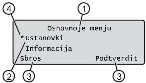
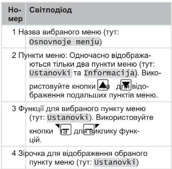
2.6 CtpyKTypa MeHIO
Osnovnoje++,
Programmy
Programma nedeli duB. po3di 7.5 "HanaumyeaHHra npoapamu ckouyBaHHra", cmopiHa 438
Punkt nachal rabot duB. po30in 7.5.2 "HanaumybaHHa euxidHX mo-OK", cmopihka 438
Program Info nB. po3in 8 "IpeaiaH opmaui", cmopiHa 440
Ustanovki
Vremya nB. po3di 5.2 "BcmaHoEneHn oChoEHX npaMempi", cmo-piHa 435
Vremja duB. po3di 5.2 "BcmaHoeJenHra ochoehux napaempie", cmopiHa 435
Jazyk DnB. po3di 5.2 "BcmaHoeJIeHHa OCHoEHX npaempie", cmopiHa Ka 435
PIN-Code ДИВ. po3di 5.2 "BcmaHOBNeHHa OCHOBHX napaMempie", cmopiHa 435
Zvuk klavishej ДИВ. po3di7.2 "YeIMKHeHHa/BUMKHeHHa CuHaJIe Ha-muckaHHa KHOJOK", cmopiHka 437
EcoMode nB. po3di7.3 "YeimKHeHHa/BumKHeHHa pexumy Eco", cmopiHa Ka 437
Quick Homing Kit nB. po3di 4.8 "YcmaHoblenHa6opy dny wbuDko2o camohabeHnra", cmopinka 435
Sensor dozhdya nVB. po3di 7.4 "BcmaHOeHnHa damuKa douy", cmopiHa 437
Zaderzhka dozh. sen ДИВ. po3di7.4 "BcmaHOBeHnHa damuKa doUy", cmopiHa 437
Chut1. datchyka nB. po3di7.4 "BcmaHoeJenHra damuKa douy", cmopiHa 437
inTOUCH nVB. po3di 7.6 "iNTOUCH", cmopihka 439
Koschenie po kraju ДИВ. po3di7.7 "Скочуваня краій пid уac 3a-nycky epyuHy", cmopiHka 439
Dopolnitjel'naja ploschtschad' aktiv/ne aktiven duB. po3- din 7.8 "HanaumybaHHN cKouyBaHHN dOdamkooi nlou", cmopinka 439
KoItrast displeja nVB. po3diN 7.9 "HanaumyBaHHa KOhmpacmHocmi duCnpe", cmopiHa 439
Zawita ustanovok ДИВ. po3di7.10 "3axucm HanaumyBaHb", cmopiHka 439
Novaja kalibrovka duB. po3di7.11 "Poemophe kani6pyeaHnra", cmopiHa 440
Zavodskie ustanovki duB. po3di7.12 "BiodnoeHHa 3aeodcbkux Ha- naumybaHb",cmopihka 440
Informacija
Servis nozha nB. po3di8 "Pepeaiai, cmopina 440
Hardware nB. po3di8 "IpeeaeiaHfOpMaui", cmopihka 440
Software nB. po3di8 "IpeeaeiaHfOpMaui", cmopihka 440
Program Info nB. po3oi 8 "IpeaiaiHΦopMaui", cmopiHa 440
Nepoladki nB. po3oi8 "IpeaiaiHfopMaui", cmopiHa 440
2.7 Ba3ObA cTaHciA (04)
| Ho-
Mep | Компонец
КOMПОЕNTа |
| 1 Базова пл actина | |
| 2 Ид с у | |
| 3 Зapor к о k | |
| 4 | К Home (Д o o o |
| 5 Зapor Sta n i | |
| 6 К Sta x x | |
| 7 З Sta n n | |
| 8标明 Sta n n | |
| 9标明 Sta n n | |
* y 3aJIeXHocTi BiD MoJeI (INB. TexHiUHi XapakTePnCTnKu)
2.8 AkymyTOp
KopncTyBauchoKe 3amHHTn akMyJrTOp.
R NPMITKA AkymyIaTOp cIiD noBHicTIO 3apraNTn nepei nepuIM BnKOpNCtAHnM. AkymyIaTOp MOxHa 3apJxKaTu Ha 6yDb-ryKomy pIBHi 3apA dy akymyIaTopa. IpeepuBaHHa 3apJxKeHN He BnNBAe Ha cTah aKymyIaTOpa. AkymyIaTOp MOxHa 3apJxKaTu, TIlbKn JaKUo npncTpI yBIMKHeHO.
AkymyIyTOP BXOINTb y KOMJIeKT NOCTaHaHn. 3a HopMaIbHOi pO6OTn akymyIyTop 3apraJxTaebcpeRyIaRpHo. Ppi cBomy npicTpii NOBepTaEcDo 6a30BOiT CTaHciI.
B6yIOBaHa BmipOBAJIbHa eIeKToPiKa aB- TOMaTnUHO npuINHc IpoUc3apJxKaHn, KOJI IOcraTaBcA 100% pIBeHb 3apAHy.
Ipouec 3apJxHnB Bi6yBaCTbcR, TINbKn KUo 3apJHi KOHTaKTn 6a3OBoi cTaHci 3HaXoJTBcR B iJealbHOMy KOHTaKTi 3 KOHTaKTHMn IOBepxHmnpucTpoIO.
3a Tempepatyn Bnue 45 ^ C B6ydoBaHa cxema 3axncty 3anobirae 3apxkaHHIO akyMnyTopa. Lc 3anobirae pyHvBaHHIO aKymyIyTopa.
Kuo yacpo60n akymyIaTopa 3NaHcCKo-poucybC, He3BaKaIOuH Na NobHy 3aprky, akymyIaTOp Heo6XiIDHO camOCTiH0 3amHtN.
Kzto akymyIop po3pJxHn HxHcpe npory Bnpo6Hnka chepe3 cTapHHa a6o TpBaIoro 36epirAHn, Ioro He moXHa nepe3apd
XaTN. DopyuItb nepeBipKy akymyIaTopa Ta BmipBoJIbHOeKeKTPoHIkN axIBIO, TexHiKy a6o cepBichOMy napThepoBI AL-KO i 3a Notpe6n 3amHITb IX.
CTaH akymyIaTOPa BiO6paXaEcTbCnHa DnCnnei.IpeBipRNeTe cTaN akymyIaTOPa NiCn3-MicuHOro 36epirAHn. DnA zuoro BBIMKHiTp npncTpi i 3HTaTne CTaN akymyIaTOPa. RaKIO akymyIaTOP 3aprJxKeHn npN6n3Ho Ha 30% a6o MeHne, NOMICTiB npNCtpi B 6a3OBy cTAnciO i YbIMKHiTb II, Ioo6 3aprAnTu akymyIaTOP. RaKIO 3aprAnHy KOlonkU dJI 36epirAHn BnuaneHO 3 6a3OBoI cTAnCi (DnB. po3di 12.2 "DeMoHmax i 36epiaHHraHoi CmAnu (18, 19), cmopinKa 446), cnpSy BCTaHOItb II B 3BOPOTHomY nopAky i 3HOBy nIKLIOuy b3a3OBy cTAnciO do Mepeki.
Ko eNekTpoi npotik B akymyIaTOPHn BiDcIK:3BepHiTbcra 3a peMOHTOM y cepBiCnH nEHTP AL-KO!
KuO akymyTop BndaJeHo 3 npncTpoU: Koo a6o pyKn BCTynnnB KOHTaKT 3 po3NITm eJekTpOitom, HeraHNO npomnTe ix BoDo. HeraHNO 3BepHiTbcn do nikapra!
2.9 Onnc cyhkuiohybaHHa
NobediHkaHa ra3OHi
Pnctpi BInbNo nepemiaeTbcra no oblaacti CkOswyBaHHra,ka BN3Hauaetbcra 6mexyBaHbHnM Ka6eJem. OpiEHTaIg npictpoIO 3diChHOCTbCRA 3a DOlOMOrO DaTUnKIB, kki BNABJIOTb MaHITHe NOle 6mexyBaHbHoro Ka6eJIIO.
Ku npctpi CTkaTb3 nepeWkoOIO, BIN 3ynHReTbca i npoobkye pyxatncB iHOMy HanpMky. Kuo npctpi Notpanne B cntyaI IO, KOJI ekCnpyataiHaMeXnBa, Ha DnCnJIe I 3'ABJcTbcNOBIDOMJeHH.
Ku npicpi BnBnE BOIry 3 yBIMKHeHm DaTukOM DoUy, BIn ABTomTuHNOBepTaEcTbcr Do 6a30BOi CTAHui.
Pobota B pexmi ckouyBaHHa 3apxkaHH
EtannsckooybaHHnoctiHNO3miHIOIbC83rIHO 3 etanamn 3apJxahnn. Kaio 3apad6aTapei Docra neBHorO 3NaueHHn iD yac cKouybaHH (cBtIoqD: 0% ), npncptpi nobepTaetcbd 6a30BOCTAHU B3doBk oMexyBaNbHorO kaBenIO. PporpAmn cKooybaHH nonepedHbo BCTaHOBneHi,ixMOXHaHaataBAtn Ha npncptoi uBdoDaTKy.
Pn Koxhomy 3anycky DBNrhyHa KocapKn 3MiHIOeTbcry Hnro HanpmaK OBeptaHH, IIO NOBHOc TepMin Cnyk6n HOxIB.
2.10 Be3dpoToBn paIIOMoIyIb Ta IdoaTOK AL-KO inTOUCH Smart Garden
Pobotn3OBaHa ra3oHOKocapka ochueta 6e3- dpoTobm paIOMOynem. Ley moIyIb 3a6e3ne- yE 3pyHHe KepyBaHHa, HanaIITyBaHHra KOHTpOJIb Ype3 DOaTOK 3 MOiNbHO npIcTPOHO (cMaprFOH, nlaHWE).
N P N M I T K A 3aiaHn Mo6IbHn npncptpi NOBHeH 6yTuPiKIOueHn Do MepeXi INTePHeT dIe BnKOpNCtAHn DaTaKa AL-KO inTOUCH Smart Garden.
I NPMITKA IJRA NOCTHNO OHOBJIeHHN nporpaMHoro 3a6e3neueHHPO6OTn3OBAHOI ra- 3OHOKOCAPKn DO HauHOBiOoi Bepci, Ra3OHOKOCapka NOBHnHa 6yTu NiE'EDHaNo MEpexi INTePHT 3a DOnOMOrO 6e3DpoTObOoi MepeXI. DoDaTOK AL-KO inTOUCH Smart Garden HAcSnlaCnOBiUeHH, KOJI 3'ABJIOTbcr nporpaMHi OHOBJIeHHI JIPO6OTn3OBAHOI ra3OHOKOCAPKn. Li OHOBJIeHH 3aBaHTaXyIOTbcra ABTomAtuHo.
ДоаТOK AL-KO inTOUCH Smart Garden
Доатok AL-KO inTOUCH Smart Garden doCTуннй дя писстpoiB ha 6a3i Android y cxobu-uzi Google Play Store, a дя писстpoiB ha 6a3i iOS —В Apple App Store:


Bickahyte QR-KoD, 06 DiHaTnca, Ra BCTaHOBTN DOaTOK AL-KO inTOUCH Smart Garden Ha Cbiu cMapToH i OTPMaTu DoaTKoBy IHOpMaUIO npo Cbiu npucpii. MoXHa TaKoB BIKOPcTOBbATNoIPO nIqKnUoyeHHBaWOrO cMapToHa Do IHTepHeTy.
N P N M I T K A Po6Ou3OBAHa ra3oHokocapKa nIeHyEbCra Liue do 6e3pOToBOi MepeXi Ha 2,4 TTc. Be3pOToBi MepeXi Ha 5 TTc He niTpnu MyIOTBcR.
Uo6 niKIOuHTnCdo Do OdaTka AL-KO inTOUCH Smart Garden, 6e3dpoToBa po6oTu3ObaHa ra30-Hokocapka i cMapTfoH MaHOb 6yTu B 30Hi diI 6e3dpoTOBOrO MapwpyTu3aTopa 3 DOCTaTHbOIO cnloIO CNrHaNy (pekOMehdaiz: miHIMyM 50%
-
3anyctiTb doaToK AL-KO inTOUCH Smart Garden.
-
CTbopiTb yHikaJIbHn o6NIkOBn 3aInc KoPNCtYBa4a:
HaTnCHiB KOnkny «BxiI/PeeCtpaia» > «PeeCtpaia».
BVeDiTb aDpecy eJeKtpoHHOI noHTn Ta napoNb.
IocTaBTe npanopey y noni «PpOHTaHo Ta npHrTo...
HaTnCiHtB KhONkY «PeecctpaCiaIy
- YbiinDb 3 nonepdHbO CTBopeHM o6liKOBIM 3aNNCOM KOpNCyBaHa.
- 3anyctitb Dncnetuepe npdknueHnaTncHyBwn KhoNky «OdaTu HOu npicTpiri
- Bukohnyte nodaJIbIbI Bka3iBKn.
R NPMITKA RaKuo po6oTn3ObaHa ra3oHOKocapka nepeCyBaetbC B 30Hi caHy 3 noraHm a6o HeIOCTaTHIM 3'EDHaHHM 3 6e3dpoTOBO IO MepeKeH, HanaTuBaHHI DoaTaK ALO-KO inTOUCH Smart Garden 6yde 3diicHeNo Iiue nicra NoBepHeHHr po6oTn3OBAHOI KOCAPKn B 30Hy 3 XOpouHM pIBHem ciHany. RaKuo ciHaN 6e3dpoTOBOI MepeXi MapuTyN3aTopa HeIOCTaTHbO CnIbHN y BCbOMy caHy, Noro paDiYc DII MoxHa po3uPHTn 3a DonomOrO IOctUHoro y npodaxi petpaHcJIaTopa.
Y BnnaKky HecnpaBHOCTi Bam MoKe DoNOMOTn DInIep i3 BcTaHOBLeHm DoaTkom AL-KO inTOUCH Smart Garden. Po6oTu3ObaHy ra3oHoKocapKy cnid po36NoKyBaTu dJa DInIepa Yepe3 DoaToK AL-KO inTOUCH Smart Garden.
Okpim BiDanaheHoro DoCTyny Do nii'EdHaHOi po60tNaBOHOI ra3oHOKocapKn,doaToK AL-KO inTOUCH Smart Garden npOnohye doaTkoBi cyHKii, k-OT cymichictb 3 iHsIMn pncTpOAM AL-KO a6o Push-nobIDomHeHHB pa3i nomJIkn.
3BE3NEKA
3.1 BnKOpncTaHHa npHaueHHaM
Ley npncptpi npn3HaeHO dI npBaTHORo BnKOpnCTaHH. Byd-Ke IHwe BnKOpncTaHH a6o HeCaHKnIOHOBAHI 3MiH Ta DONoBHeHH KOHcTpyKciBBaxaIObC BnKOpncTaHHM He 3a npn3HaueHHm i npn3BOJrB Do aHyIOBaHHraPahTii, a TAKOX BTPaTN BiNObiIDHOCTi Ta BiIMOBu BiD 6yDbKaOi BiNObiJaNbHOCTi BnPo6Hnka 3a WKOdy, 3aBDAhy KOpNCTyBaueBi a6o TpeTI CTopoHi.
OnepaiciHi MeKi npncTpoI: INB. TexHiChi Xapak-TepcntKn.
3.2 MoKJIbHe HEnpaBnJIbHe BnKOpNCtAHH
Ley npicptiH He iDxOAnTb Ira BnKOpncTaHHB napkax, cKBepax, Ha cNoPTuBHnx MaJdaHnKax, a TAKoX B ciNbcbkOMy Ta NiCObOMy roCNOapcTBI.
3.3 3an06ixhi Ta 3axnchi eJeMeHTn

KIO BIn He 3a6pydHeHn;
I KIO BIn He NOnIKoJKeHn i He 3HOWeHn;
I KU O BCI eIeMeHTN KepyBaHHra npaIO- IOTb CnpaBHO.
Ko 6a0Ba cTAni i 6nok XnBneHna, a TAKOeEeKtpnHi Ka6eni He noWKoJxehi i cnpaBhi.
3aBxDn 3amHIOTe Bci HecnpabHi deTani Ha opurihanbHi 3anaChi yactHH BiD Bvpo6Nka.
Upa3i nouKoJxHnI npucTroIO BiDpeMOHTynte Ioro.
Bnachnk npncptpo Hece ocobncty BiNObiDaIbHicTh 3a HeuacHi BnapKn 3a yactIO HIXNX IIOdeA60 IXhborO MaHa.
3.4.5 EJektpnHa 6e3neKa
YkoHomy pa3i He BnKOpncToByte npnctpi, kUO odHocHo Ha ra3OHi npaioe DouBaIbHa yCTaHOBka.
YHnKaIe nOtpaJIaHHa 6pN3OK BoIN Ha npNCTpii.
He BiDkPnBaIte npncTpi.
4CKJIADAHH
4.1 Po3naKoBvBaHnI npIcTpoI
- 06epexkno 3HimiMb ynakyBaHHa.
2.ObepeJHO 3HIMITb yci KOMnoHEHTn 3 ynaKyBaHHI nepeBipTe HaRBHICTb NOIKoJKeHb NiJ Yac TpaHCnOpTyBaHHa.
Ipumimka: Y pa3i Ha8bHocmi nowkoedhen iid yac mpaHcnpmyBaHH Heauno nobido Mme faxieua a6o cepicno napmhepa ALKO.
3. Пере tipTe KOMпнгКТ NOCTaЧАнг, ДИВ. PO3-01N 2.1 "KOMпнгm NOcmaЧAnHg (01)", cmo-piHka 425.
KuO Bu 6yTe BiDnpabnT npucpii dani, 36epexitb opirihbHy ynakobky Ta cynpobidni DokymeHTN. BOH TaKoK Heo6xDiH i nna nobepHeHHa.
4.2Панобпскowуванн (05)
Po3miueHHra6a3oBOOCTAHcii (05/1)
HaiKopoTm MapuT do 6iIbwoi obnactickoUyBaHHa
Pibha nobepxha
3axnCT BiD npMOrO coHryHoro CBITna Ta cnIbHNX IORoHNx yMOB
MoxnBicb npKIOeHHy 6IOky XINBneH H
BilbHn doctyn dny po6oTn3ObaHOI ra3oHoKocapKn
PpoknaaHnO6mExyBaIbHoro Ka6eJIO (05)
O6MeKyBaJIbHn Ka6eIb cIiD nepemiuataN 3a ro- DHHNKOBIO CTPIIKOIO B 6e3nepepBHomy KOHTypi.
PpoxoMix o6JaCTaMn cKoUyBaHn (05/h)
Iproxid-ueBy3bKeMicheHa ra3OHi,kae MoKe cnykntn Dnna 3'EdHaHHaDBOX NOBepxOHBCKoWyBaHHa.
OchOBHa i doaTKoBa nloca (n) (05)
OchOBHa ploua (05/HF): Lcra3OH, Ha kOmy po3taoobaHa 6a3Oba cTaHzij, kIn MoKe aBTOMaTHUHO CKOuYBaTnC8 3a DOnOMOrIo npncTPOIO NO Bci nIooi.
ДодаTKOBа плоба (05/NF): Le ra3oH,doякого пострий He може діctаTNCS 3 ochOBHOI плошi. Ппсстрий HeobxIDNo BpyHy pepeHECTn Ha ДдотКOBу плошy.ДодаTKOBI плошi можнa обрблЯТиВ ржIMI pyHoi pO6OTn.
Ondak ochobhi Ta odaTkoBi nlooi obmxeHi odHn m i Tm Jne NocniIOBnM obMeKyBaIbHnM ka6elem.
Po3TaUyBaHnBnXiDnHex ToOc (05/X0-05/ X3)
Pnncptpi nepemiuacbcr B3IOBX 6mexyBaHb-Horo Ka6eIIO 3 φIKCOBAHUM Yacom CKOswyBaHHa Do φIKCOBAHOI BHXIDHOI TOKNI NOUHaEc TaM CKOswyBaHHa.
IouatkoBI TOCKN Do3BOJIOb Bka3aTN, kKi DInHKNObnacti cKoUyBaHH6byNo cKoUeHO.
4.3Плг罗ТУВаньообл acti ckoшуВаньо
- IpekehauTeecB TOMy, 0o nloaa ra3ohy 6Ibsha HIX NOTyXHicTh Ha OdnHnIO NOBepx-Hi npncTpoH. Ra3OH 3aHaTo BeNkN, To TpaBy 6yde 3p3aHO HepiBHomipHo. 3a noTppeBn 3MeHwiTb nlouyra3OHy, Ka niDnjarac CKouyBaHHIO.
- IpepeBCTaHOBHeHHaM 6a3OBoi CTaHci i o6-MexyBaIbHoro Ka6eJIIO I BBeJeHHaM npICtpoHO B EKcNlyaTaUIO: CkOswYte ra3OHra3OHOKOCAPKOIO Ha Hn3bKi BNCOTi.
- BuaJIbIb nepeuKoHn Ha ra30Hi a6o oMexTe ix 3a donomoro oMexyBaJbHoro Ka6eJIO (INB. po3dIn 4.5.3 "I3onrai nepeuKoD", cmopinka 433):
nIacki nepekoDni, kI niI qac nepeizdy MoKytb NOnKOdInHIX (HaNPnKnaI, nIacki kameHi, nepexoN 3 ra3OHy Ha Te-pacy a6o dopixkN, pIHTu, 6OpDOpn To-
OTBOPN Ta NiDHeCENHHa ra3OHi (HapnKnaI, Hopn Kpota, po3pnti OTBOPN, COCHOBI uuKn, naaannrTOUO)
Kpyti niДиOMn a6o cnYcKn, IIO nepeBnIyOTb 3HaueHnB, Bka3aHi B TexHiHnx xapakTepNCTnKax
BODa (HapnKlaD, CTaBKn, CTPymKn, 6aceHN TooO) Ta ixHraDemapkaia Ha ra30Hi
KyuTi Ta KINBOONOTN, IIO MOKyTb PO3uHpOBaTnC
4.4 MoHTax 6a3OBoi cTahui (07/a, 17)
1.ДоаиTe 6a3OBy cTanciIO (05/1) 3riIHO 3 3a-ПlaHOBaHIM NOLOXKeHHM O6MeKyBaJIbHOrO Ka6eJIIO TaKIM YINOM:
Ha pIBHI 3emni (nepeBipTe 3a donomoroio pIBH)
IprMnipBnCnycki niIDNOM
He nocenhen (niac npkpyuBaHHra30HnX TBnHTIB 3apndHa cTAnCi He NOBnHnA 3nHaTncs a6o po3nHaTncs)
2.3akpiitb 6a3OBy cTahciio (07/2) YoTnpMa ra-3OHHIMN TBnHTamn (07/1) do 3emni.
Ba3OBy cTaHciIO MOxHa TaKoX Po3MiCTnTn No3a TpaB'YHM NOKpTTTAM (17). O6MexyBaIbHn Ka6eNb Notpi6HO npoknaCTn TaK, YK 306paXeHo Ha CXemi.
4.5 BctaHOBJIeHHo6MExyBaJIbHorO ka6eIIO
H NPMITKA JaKIO O6mExyBaIbHn Ka6eIb 3 KOMJIeKTy NOcTaUHn 3aHaTTo KOpOTKn, MOxHa npIb6aTu NODObKyBaU y DInIepa aO cepBicHoro napThepa AL-KO.
4.5.1Пдкюченяобмexуbaь Horo ka6eIIOdo 6a3OBoi cTaHci (07/b)
- BnmiTb obmexyBaIbHn Ka6eIb (07/4) 3 ynaKyBaHHra.
- 3HIMITb KpNkky Ka6eNbHOi JaxTn (07/3) 3 po3'Emy (07/A).
- Bndaɪtɪb iɔːŋaɪzɪ 3 KɪnzəʊmɛkjBaɪbHoRo Ka6eɪn (07/6) i BCTaBte B Knemy (07/7).
4.3akpiuTe Kneemy.
- PpoknaTb obmexyBaHn Ka6eNbYepe3 Ka6eHbN BBiD (07/5) 3 3anacom Ka6eHIO 3 Ka6eHbHOI WaxTN.
H PnMITKA 3anac Ka6eIIO TaKoX MoJHa BnKOpNCTOByBaTn DnI NaJaBWoO BHeceHHa HeBeNIkX BnPapBneH B npOKnaDaHHa Ka6eJIIO.
6. BcTaHOBiTb KpIuKy Ka6eNbHOJ WaxTN.
4.5.2 PpoknaaHnHa 6MeKyBaIbHoro Ka6eJIO (05)
O6mexyBaIbHn Ka6eIb MOxHa BCTaHOBHTn Ha ra30Hi, a TakoX Ha BiDCTaHI 10 cm NiD DEpHOBIM NOKPOBOM. YcTaHOBJIeHHr NiD DEpHOBIM NOKPOBOM NOBHeH 3diCHOBaTI qaxiBeUb.
5.2 BcTaHOBHeHH OCHOBHn npaMeTpib
- BiДкриTe кршky.
- YbIMKHiTb npnctpii 3a DOnomoroio .6paXaetbcBepciMikponporpamH, Homep Kdy Ta TIN.
- B MeHb Bn6Opy MoBn 3a DOnomoro
Bn6epitb MOBy i niTBepeiTB 3a donomor
4.B MeHIO RegistraraciJa > Vvedite PIN BBeDiITb PIN-koD 3a 3amOByBaHHm 0000.
Bn6epitb cnppy 0 3a donomoroio Ago i niTbePdltb 3a donomoroio .ficna BBeDeHHa PIN-koDy doCTyn po36nokyetbcra.
5. Y MeHIO Izmenite PIN:
BVeIb niVvedite novyj PIN HOBn yOTnpu3HaHn PIN-koD. Bn6epiTb cnOprn Onda 3a OndHO 3a donomoroIO a6o nTBePdITb 3a donomoroIO
Ie pa3 BBeItb niPovtorite novyj PIN HOBn PIN-KoJ. RaKIO o6nDbBA BBe-DeHHa 36iraTbCra, To 3'ABITbcra NOBiDOMJIeHHa PIN uspeshno izmenen.
- B MeHIO Vvedite datu 3aJaTe noToUHy DaTy (ΦopMaT:ДI.MM.20PP).Bn6epiTB
UOHa 3a OHO 3a DOHOMOIO 6o TBPdITb 3a DOHOMOIO .
- B MeHIO Ustanovite vremya > 24h- Format 3aJaTe nToUHn Yac (Φop-MaT: ΓΓ:XX). BnBepiTB uOcPn OHa 3a OHO 3a DOnOMoROo i TBePdIb 3a DOnOMoROo
Ochobhi hanaityBaHHB BCTaHOBneHo. BiO6paXaetbcraTah Ne kalibrovan Nazhmite knopku START.
5.3 HanaTuBaHHB BnCOTn 3pi3y (14)
Bncota 3pi3aHHn noCTiHNO peryIIOeTbcra 25-55 MM BpyHy.
I PPUMITKA IЯ kai6pyBaHHa (nB. po3in
5.4 "Bukohann aemomamuHoo kaibpyaHn",cmopinka 436)i nporpaMyBaHH BxixHnx ToOK (nVB.po30in 7.5.2"HanaumyeaHn buxidhux mook",cmopinka 438) pekomehnyetbcra BncoTa 3pi3y 55 MM.
- BiДкриTe Кршky (14/1).
- BiDperyIIOHe BucOTy 3pi3aHHa (B orJIOBOMy BIKHi B MinImeTpax BiO6paXaεTbcraNoToUHa Bucota 3pi3aHHa (14/3)):
36iJIbSeHHBnCOTn 3pI3aHHN (TO6TO BnCOTn cKOUyBaHH): NOBepHiTb IOBOPOTHy pyKy (14/2) 3a roDINHHNKOBHO CTpiIKOIO (14 / + )
3MeHWeHHBVCOTN 3pi3aHHn (To6TO BNCOTN cKOUByBaHH): NOBepHiTb NOBOPOTHy pyKy (14/2) npOTn rOdINHHKOBoi CTpiJIKn (14/-).
- 3akpnIte KpnIky.
5.4 BnKoHaHHaBtOMaTHUHorO kaJI6pyBaHHa
RnPIMITKA BnKoHaIe TcIKN KaIbpyBaHn (DNB. po3di 5.4 "BuKoHaHHaemomamuHHOZ Kani6pyBaHHa, cmopihka 436) abo Bkaxitb noaTkoBI ToUKN (DNB. po3di 7.5.2 "HaNaumyeaH H buxidHx moOk", cmopihka 438) nepei noaTkom BnKOpNCtAHn.
BcTaHOBJIeHHBAHXiDHoro noIoxKeHH npIscTpoIO (13)
- BctaHObIb npucptpiB o6nacti cKoUyBaHHB NOuATKOBE NOJOKHeHH:
MIn.1 M nibopyu i 1 M nepei6a3oBOIO CTaHcieI O
BnpiBHHN3 npeDnHbOu qactnHOo 6-MexyBaJIbHOrO ka6eJIIO
3anyck kaJI6pyBaHHa
- NpebipTe, uH HeMaC nepeKoD B ouykBa-Homy diana30Hi nepeMiueHHra npncTpoH. Pnctpii NOBHeH MaTH MoXJIbICt b nepeix- DkaTn uee3 6mExkyBaJbHN Ka6JIb OndHOacHo 6Oma nepeHIMN KOneCAMn. Y pa3i notpe6u yCyHbTe nepeKoDN a6o npokla-DITb Ka6eJIb BCEpeDiHi (Minlmy 35 cm 3abTn6kN).
- 3anyctitb npnctpii 3a donomoroio .HdncnneB iDobpaXaETbcA:
!Vnimanie! Start privoda
Kalibrovka, Faza
Пд часкалібруваимь.
Uo6 Bu3HaunTp pBeHb CnHaNy B 0mbexyBaHb-Homy Ka6eIi, npncptpi CnoaTky npoxoNTb Dbiu npraMo no 0mbexyBaHbHomy Ka6eIIO, a NOTIM NO 6a3OBi CTahci i 3ynHReTbcr TaM.
Ha dincnei 3'YBnTbcK Kalibrovka zakonchena.
AkymyITop 3apJkaeTbcra.
8 NPMITKA Ha Bxodi B 6a3OBy cTaNciIO npnctpii NOBHe H 3ynHHTbc. JaKIO npncpti He NOTpanJIe B KOHTaKTn Ha BXoI B 6a3OBy cTaNciIO, BiN pOdoBxNTb pyX no O6MeKyBaIbHOMy Ka6JIIO. JaKIO npncpti nepemiaCTbcR No 6a3oBi CTAHcII, ue O3Naue, 0 npocec Kani6pyBaHN He 6byo 3abepseHO. B cIbMy pa3i 6a3OBy cTaNciIO cIid BnpIBHrTHn HaneKHM YINHom i Nob-TopNTn npocec Kani6pyBaHHra.
Picna kaIipyBaHHa
Bido6paKaeTbcra 3aHa nToUHa TpNbAicTbCKoUyBaHH.
Дя BCix iHux HanauTyBaHb nVB. po3di7 "Ha- naumyBaHHa", cmopiHa 437.
Robolinho
N P N M I T K A 1nla 3a6e3neueHH HaJIeXHOro 0yHKUIOHyBaHHra Ta 3MeHWeHHa KINbKocTi NOBI-OMJEnb npo NOMIKn HeO6XiHO BmIpA rtn DOBxHny nTni 3a DOnOMoroIO OyHKuII «Ii3HaTnca TOUK BXOdy>.
6 EKCnIyATAUIA
6.1 3anyck npnctpoBpyHy
- Ybimkhitb npncpti3a donomoro 0
Ira Hepepynphoro cKoWyBaHHK paiB: nB.
po3di7.7"CkowyBaHHK paiB niO yac 3a-
nycky bpyHy", cmopinka 439.
- 3anyctitb npncptpiBpyHy 3a donomoroio
6.2 CkacyBaHHpoBToBpeXmICKOswyBaHH
HaTnCHiB a6a3oBi n cTaHci (12/4) a6o Ha npncTpoi.
Pnncptpi ABOMATUHO NOBepTaTbC8 Do 6a30BOI CTAHII. BIn BNdaJIe PIIAN CKOuYBaHHN oTOUHOrO DnI I nepe3anyckaTbC8 Ha HAcTyHNI DeHb Y BCTaHOBJIeHNI Yac.
HaTnchItb KhoNky npncIpoi. Po6ota B pexmI cKOswyBaHnI nepepNBaETb- CnHa nIB rOuHN.
HaTnCHiB KHONky Ta npucTroI.
PiNCTpi BUMKHeTBcR.
N P N M I T K A Y He6e3neuHnx CnTyauix npnCTpi MOxHa 3yINHHTn 3a DOnOMOHO KHONKSTOPP (12/2).
6.3 CkouyBaHHaOaTkoBoi nlooi (05/NF)
1.Пдимитьnpстп i BCTaHOBiTB noro BpyHy Ha doDAkOBy nloу.
2. Ybimkhitb npnctpi 3a donomoro
- Binknutyte roJOBHe MeHIO 3a Donomoroio
4.a * tanovki
5. a * sAschiwanije dopolnitjel'noj ploschtschadi
- Bn6epitb yac cKOuSyBaHHa 3a Donomoro a6o

- 3anyctitb npncptpiBpyHy 3a donomoroo
3aIexHo BiD HanaaTyBaHHr: PnucptpiB BIKOHycCKoUyBaHHB 3aHaHn Yac, a NotIM BmMkaeTbCra abo npoDoBXyE cKOuYBaHHr, DOKn aKymyJr-Top He po3pRdntbcr.
Nicra cKoUyBaHHaOaTKOBoi nNooi 3HOBy BCTaHOBtB npictpiHa3aD y 6a3OBy CtaHciIO.
7 HAJIaHTyBAHHY
7.1 Buknk HaJaTaYBaHb 3araJbHi
- BnKInuTe roJIOHe MeHIO 3a donomoroio .Ipumimka: 3ipoOka * nped nyHKmOM MeHIO 6ka3y6, uO e ue yac BOH Bu6paHI.
2.a * ustanovki
3.Bu6epiB noTpi6Hn nyHKT MeHIO 3a DOIOMO-TOo 60 i TBePdITb 3a DOIOMOIO
- BctaHOBt b hanaTuBaHHa. Pumimka: IyHKmu MeHIO OnucHo 8 Ha-cmynHex po3diJax.
5.Повернівсяdo ГолOBHOrO MeHIO 3a ДОпOMOTO
R NPMITKA IHHI NyHKTN MeHIO: nVB. po3diN 5.2 "BcmaHOeJIeHHa OCHOBHX napaempiE", cmopiHa 435.
7.2YbIMKHeHHBUMKHeHHCnHaJIH HATNCKaHHKHONOK
1.a * kklavishej
2. YbIMKHeHHBbIMKHeHHcHHaJIb HaTnCKaHH KHOHOK:
a6oapustit': yBIMKHeHHcHnIBHaTnCKaHHKHO- nOK.
a6oVeakt.:BIMKHeHHcHHaJIbHaTnCKaHHa KHONOK.
7.3 YbIMKHeHHBIMKHeHHpeXMy Eco
B pexmi Eco npucpi nepemkaetbca B ehep-ro36epiraoun pekm. Lc 3nKy eheprocnoxnBaHHi piBeHb wmy.
RnPIMITKA Ley pexHm He peKOMeHIOBaHn a6o HeOCTynHb pa3i BucKOoi i 1JIbHOTo TpaBn, a TaKoX 1IbHOpyNoHHOro ra3OHy.
- aMode
- YbIMKHeHHBbIMKHeHHpeXMy Eco:
Zapustit' yBIMKHeHHpeKmMy Eco.
Deakt. BIMKHeHHpeXmMy Eco.
7.4 BcTaHOBHeHHaTUnKa DoUy
N P N M I T K A C K O W U B A H N H C y x o i T p a B N 3 m e H w y e k i n b k i c t b 3a6p u d H e H H. l J I X O M a K T N B a C i D a T Y N K A D O S U Y I B C T A H O B L E H H Y a C Y 3 a T P N M K N M O X H A 3 a n o 6 i r n C K O W U B A H H I O n p n c T p o E M M O K P O I T p a B N.
KoI NaTnK DoUy aKTNBOAHO, npucpii nobepTaetbca Ha 6a3OBy cTahciIO, KOJI nDe doU. BIn 3aIIuwaetbca TaM, DOKN DaTnK DoUy He BnCOxHe. Notim BIn Ouyke npotrarom BCTaHOBneHoro Yacy 3aTpIMKn, nepu HIX npoDobXHTn Oepaio CKouyBaHHa. UytlnBicTB daTnKa DoUy peryJIOeTbcra.
1.a * sensor dozhdya
2.YbIMKHeHHBIMKHeHH DaTUnKa DOUy:
a6oapustit':yBIMKHeHnDaTUnKaDoUy.
a6oBeakt.:BIMKHeHHaTUnKaDOny.
- BcTaHOBJIeHHaTpIMKn DaTUnKa DoUy:
a6o Zaderzhka dozh. sen
xx chasov xx minut Bn6epiB 6aKaHe 3HaueHHe 3aTpIMKn 3a DonOMOrOo , TBePdIb 3a DonOMOrOo
- BctaHOBenneHH yU TINBOCTI daTnka douy:
a6o chut1. datchyka
Bn6epiB 6axKaHe 3HaueHnYyTnBOcTi 3a Donomoro1o a5o , TBePdIb 3a Donomoro1o
7.5 HanaTsyBaHH nporpaMn ckowyBaHH
7.5.1 HanaштуваимпPORpamNCKOswyBaHH - 3araJIbHi
- BnKInuTe roNoBHe MeHIO 3a DonomoroIO .
- a * Pgrammy
3.Bu6epiTb nyHKT MeHIO 3a DonomoroIO i niTBePitb 3a DonomoroIO
- BctaHOBiB hanaWtYbaHHaPumimka: NyHKmu MeHIO ONUcaHO 6 Ha-cmynHux po3dinax.
7.5.2 HanaatyBaHHBnXIDHnTOOK
BnBueHHnoaTKOBNXTOOK
- BctaHOBIb npncptiB 6a3OBy cTaHcIIO.
- YbIMKHiTb npncptpi 3a donomoroIO
- BnKnUte roJIOBHe MeHIO 3a DonOMoroIO .
- a * Pgrammy
- a * Punkt nachal rabot
- a* opredelenie puti
- a * Start oznakomitelnoj ezdy po punktam start
a6o start .Pncptpi nepeMiuaactbca B3doBx O6mexyBaJbHoro Ka6eIIO. a6o des' , npncptpi IocarHyB 6axaHO BnxiDHO TOckn.BuXiHa Toka 36epiraetbcra.
- a Vveite punkt starta 1 , kio BnixiHa Toyka He 3aHaHa nI yac HabuaHbHO i Noi3Kn. KIO noaTkoBy Tocky He 3aHaHO, TO noaTkoBi ToyKn 6yde BCTaHOBJIeHO aBTOMaTHNO.
- a Punt starta x: XXm, -KoIb6yIIO DOcRHyTO OCTaHHboI BHXiDHOITOuKN.
BcTaHOBHeHHaNoaTKOBHX ToOcK BpyHy (05)
Iepwa noataKoBA ToUka (05/X0) 3aDaHa i 3haoDntbcra B 1 M npabOpuy BiD 6a3OBoi cTaHcii. 3a ciEIO TOUKOIO MOxHa 3anporpaMyBaTn DoaTkoBI BUXiHi ToUckN (INB. TexHicHI XapaKTepeNCTNK).
7.5.3 HanaTsyBaHHa cacy CKoWyBaHHa
H NPMITKA MIX nporpaMyBaHHM yacy CKOuYBaHHI I NOaTKOM CKOuYBaHHMaE npoHTn He MeHwe 30 XB. B iHaKwOmy BnAky npicTpI 3anyCTntbcr He paHIe, HIX 3a 30 XBnINn NiCJn OCTaHHbOrO HaTNCHeHH KJIaBiIi.
IyHKT MeHIO Programma nedeli BnKOpncToByEcbcA DJIa BCTaHOBHeHHa DNi HAcy CkOuYBaHHa PnucTrooem.3a Notpe6b BCTaHOBItb ci HanaWtBuHHa BiNobIDHO Do po3mipy caHy. RaIO Bu NOMITE Heo6pOBeHNI DInrHKn Pnp6n3HoYepe3 TnKDeHb, 36INbWiTb Yac CkOuYBaHHa.
- a * Pgramma nedeli
a6o Vse dni [X]:Pnucptpi BnKOHye CkOuYBaHHaODHb3aHaHn Yac. KIO BiO6paKaeTbc8 Vse dni [ ]TO npcTp i 6yde BnKohyBatn CkOuYBaHH TInbKnB 3aHaHdHnTnxHn.
a6o Ponedel'nik [X]... Voskresenje [X]:PnncptiBnkoHye cKoUyBaHHB 3aHaHi dHi TnxHn. HApNKpA, kIIObpaKaetbcPonedel'nik [ ], npncpti He 3diHIOE cKOUyBaHHN OJHn.
a6o zmenit':YBIMKHiTb [X] a6o BIMMkhITb [] y BiIDnoBIiHnI
DeHb, BCTaHOBITb Yac, TIN CKOWyBaHHa I BNXiDHi TOUKN.
- BcTaHOBnEHHaIaWtYBaHb DnI BCIX DNIB a6o neBHorO dHra:
HapnKnaI,*[M]07:00-10:00[?]: 3BnuaHHe cKOuSyBaHHra[M]307:00do 10:003abTOMaTHUHO 3MiHO BUXiHOITouKnO-9[?]
HapnKnaD,*[R]16:00-18:00[1]: Pnucpii 3ayncKaetbCra 16:00BpeKni Mi cKOswyBaHHa KpaIB [R] i nepemiaeTbcra B3doBx BCBOO oMExyBaJIbHO ra6eIIO. Picra 2bOro nouHaCTbcra cKOswyBaHHa IIoU3 BVxIDHOI ToCKN 1 [1]. O 18:00 a6o 0oiHo aKymJrTop po3pndTbcra, nucpii NOBepHeTbcra Do 6a3oBoi CTahii.
a6o zmenit':3HITb BN- 6paHnauTuBaHH.
a6o 而ed:TbBepiTb 3MHeHi HaIaWtYBaHHia npeeNITbdo NaCTyHnX.
- a SoHanite:36epexiBci 3MiHeHi HanaHTyBaHHn NyHKTy MeHIO.
7.5.4 Pexim npoxoib
Pexm npoxoib Do3BOJAEOTpMaTn Kpaun pe3yIbTaT CkOswyBaHHa By3bKnx npoxoax.
- BnCTaBTe NOaTKOBy TOky CkOswyBaHHy y By3bKOMy npoxoDi (INB. po3in «BnCTaBNeH-H NaOTaTKOBoI TOkN CKoWyBaHHA»).
- Po3nohItb po6Otu B pexnmi npoxoJIB 3 Bu-CTabJIeHOI TOUKN CKOuYBaHHa (INB. PO3dIn «BnCTabJIeHHn IporpaMn CKOuYBaHHa)
HapnKna: [P] 16:00-18:00 [3]: Pnpctpi pO3nohe po6oTy B peXmI npoxDiB [P] o 16:00 3 noaTkoBoi TOnKn cKoUyBaHHa 3 [3]. O 18:00 a6o IooHNo a-KymJrTop pO3pAHTbcra, Pnpctpi No-BepHeTbca Ha 6a3oBy CtAHciHO.
7.6 inTOUCH
HaBHe 3'EDHaHHa 3i UHIO3OM MOKe 6yTN BIMKHeHO. Lepn3BeDe Do TORO, 10 npncTpi 6yde BiKpITo dJa HOBOrO 3'EDHaHHa npOTaROM 30 XBNIH.
8 PPUMITKA 5o6 BCTaHOBnTn 3'eHaHHnPi-3HiIe, 3'eHaHHn Heo6xIDHO CNoaTky BmKHyTN, HabItb kUO npncTpii paHlwe He 6yNo ndknoyeHo Do UJIO3y.
- a *inouch
2.vimknennja z'ednannja - NobiDompeHn npicTpo: Gotovo.
3.ПИДТВЕРДITb 3a ДОПOMΟΤΟΥ ΦВЕРΗΙΤΒ-CΑВ MEΗΟ.
7.10 3axnct HanaaTyBaHb
KxO 3axnCT HanaTByBaHb BmKHeHO, PIN-KoHne6xIDHO BBOHTN TiIbKN Ba pa3i NOMInKn, NOB'3aHOI 3 6e3neKOIO.
- a* zawita ustanovok
- YbIMKHeHHBbIMKHeHHaXnCTy HJaTaTyBaHb:
a6o apustit': -YbIMKHeHHaXnCTyHaNaWtYaBaHb.
a6oVeakt.:BIMKHeHH3axNCTyHaNaHTyBaHb.
7.11 Nobtophe kani6pyBaHHa
KuO Micpe po3TaUyBaHHa 6o DOBxHy OMeKyBaHoro Ka6eIIO 6yNo 3MiHeHO a6o KaUO npucpti He MoKe BnABHTN OMeKyuBaHn Ka6eNb, Notpi6He NOBtOpHe Kani6pyBaHHa.
- novajakalibrovka
- Vernut'sya v prezhnee sostojanie?
- Bukohann KaibpyBaHH: nB. po3di 5.4 "BuKoHaHn abmammuHozo KaibpyaHn"cmopihka 436.
7.12 BiHOBJIeHHaBOOcBKnxHaJauTyBaHb
3aOcBki HanaU TyBaHH npncToPO MOxHa BiHOBHTN, HapnKNaI, nepe npdaXem.
- a* zavodskie ustanovki Nobidomnenny npncpoU: Ustanovki uspeshno vosstanovleny
8 INPERIJIAD IHOPMALI
MeHIO Informacija BnKOpncToByc8aIra BiDobpaKeHHiaHΦopMaciI npo npicTpIy Ucbomy MeHIO MoXHa BCTaHOBNIOBaTn HanaSTYBaHHa.
- BnKnHrTe roNoBHe MeHIO 3a DonomoroIO .
- a * formacija
3.Bu6epiB nyHKT MeHIO 3a DonomoroTO Ta nITBePdIb 3a DonomoroIO
Pumimka: NyHKmu MeHIO ONUcaHO e Ha-cmynHex a63aux.
4.Повернітбяdo roJOBHOro MeHIO 3aДOnOMorOIO
Servis nozha
Bidobpaxae roHHn po6oTn, kni notpi6hi dIra o6cnyroByBaHHa HOka. IiHnhK MoXHa cKHyTu BpyHy. Dopyitb 06cnyroByBaHHa HOka qaxibu, texhiky a6o cepbichomy napThepoBi AL-KO.
CkndaHHniiuNbHka 06cnyroBaHHn HOXA:
- Podverdit
Hardware
BiO6paKa e iHOpMaciIO npo npicTpi, k-OT TnP, pIK BnPyCKy, roDHHpo60TN, cepiHm HoMep, KInbKiCTb KocapOK B KomnneKti, 3araIbHm Yac cKOswBaHHa, KInbKiCTb ZNKJIb 3apJdKn, 3aIaIbHm Yac 3apJdKn, DOBxHa oMexyBaIbHoTo Ka6eJIHO.
Software
Bidobpaxae Bepci nporpaHoro 3a6e3neueHHra.
H NPNMITKA 3aBxdi OHOBJIOnTe nporpamHe 3a6e3neuHnpo6OTn3OBAHOI ra3OHOKocapKn Robolinho. Perynpho nepeBipnye BepciO mikponporpam, 3a Notpe6n OHOBJOnTe II. Bu moKeTe 3HaHTN OHOBNeHH nporpamHoro 3a6e3neueHH Robolinho B iInTepHeti 3a aDpecoH: www.al-ko.com/shop/de/robolinho-autoupater
Program Info
Bidobpaxae notochHaHaaTyBaHHraK-OT yBeCb 3araJIbHn Yac CKOuYBaHHa TINXDeHb.
Nepoladki
BiO6paKaε octaHHi NOBIOMJIeHHI npo NOMJIKn 3 KOdOM DaTn, Yacy i KOdOM NOMIKN.
9 TEXHlUHE OBCJyROBvBAHHaT A DOrJaI
OBEPEXKHO! He6e3neka TpaBMyBaHHJ.
Pyxomi Detani Ta Detani 3 roctpumn KpaMn MoKyTb npn3BcTn Do TpaBM.
3abxHn Hocitb 3axnchi pykabuizi nd yac texHiyHoro i cepBichoro o6cnyroBaHHra Ta OunueHHa!
9.1 OuHnHn
YBAGA! He6e3neka uepe3 noTppannHnBaOu. IopTpannnHb ODo Bpo6OtN3OBaHy ra30HOKocapky i Ha 6a3OBy cTaHcIO BVKnKae NOUKOJxKeHH eJeKtpnHx KOMNoHEtIB.
He obnpnckyte po6oTn3ObaHy ra3oHOKocapky i 6a3OBy cTaHciIO BDOIO.
OuHHeHH po60Tu3OBaHOi ra3OHOKocapKn
OBEPEXHO! Hebe3neka OTPMaHHa TpaBM,HaHeceHx HOxEM.Hix dyxe roCTpni MOKe 3aBdATn TpaBM.
BnKOpncToByuTe 3axnChi pyKaBuNci!
IpekeohaiTecB TOMy, 0u cactnH Tina He KOHTaKTyOToB 3 HOxEM.
BukohybaTn OINH pa3 B TnKdEh:
- Bumkhitb npncpti3a donomoroio .
2.ПрOTpiTb NOBepXHIO KOpNcY neH3nEm,UIITKOHO BOJOrOHO TkaHnHO a6o ToHKO r6KOHO.
- Ouictb dHO, Kocapky i HixiTkoHO.
- IpepeBipTe HIX Ha npEaMeT NOUKOJKeHb. 3aMiHiTB 3a Notpe6n: DnB. po3di9 9.3 "3aMinaHOxa", cmopiHa 441.
OuHHeHHa3oBoi CTaHcii
- Perynnapno Buaanrte TpaBy i nctra 6o H- u npdmTu 3 6a0BOi CTauii.
- OuNCTITb NOBepxHIO 6a3OBoI cTaHcII BOnToIO TkaHnHOo a6o ToHKOI r6KOIO.
9.2 Perylnarhi Bnnpo6yBaHHa
3araJIbHI Bnnpo6yBaHHa
- IpepeBiprIe BcIO yCtAHOBky pa3 Ha TnXJDeHb Ha npEIMeT NOWKoDKeHb:
Ppnila
Ba3ObCtAHcIa
06mexkyBaIbHn Ka6eIb
6nOKXINBHeHHA
- 3amHITb HecnpaBHi DeTani Ha opurihalbHi 3apanachi YactnHi BiD Bnpo6HnKa afo DopyuHt bIXHIO 3amHy cepBicHOeHTpy BNpo6HnKa.
Ipebipka BilbHoro xOdy poJNKIB
BnKohyBaTn OdnH pa3 B TnXkDeHb:
- PeTeNbHO ouHCTiTb DiJnHKn HABKONo poNikB BiD TpaBN Ta 6pydy. Ppi CbOMy BnKOpNCToBByIe neH3eNb i TkaHnHy.
- IpepeKoHaTecB TOMy, 0o polnKn BiNbHO npemiuOHTbcN ynpabIIOHbCra.
Ipumimka: Ka o pounku 3 npaueo nepemiuombc a bHe ynpaaonmbc, dopyimixamHy cepichomy uehmpy bupobnka.
IpeBipka KOHTaKTTHx NOBepXoHb Ha po60tN3ObaHi ra3OHokocapci
- OuNCTiTb 6pyd TkaHnHOIO i 3nerKa 3MaCTiTb KOHCnCTeHTHM MaCTINOM.
Ipebipka 3apdHnx KOHTaKtIB Ha 6a3obin ctaHci
- BnMItb wTekep.
- Hatachitb i BiDnyctiB 3apAHi KOHTaKTH B HaprMky 6a3OBoi cTahci. 3apAHi KOHTaKTH NOBHHI NOBepHyTncB NocATKOBE NoNoXeH H
Pumimka: Kaio 3apadH KoHmakmu He no
eepmaombca, dopyimbix 3amHy cepeichomy uehmy bupobhuka.
9.3 3aMiHa HOXa
OBEPEXKHO! He6e3neka OTPMaHHa
TpaBM,HaHeceHnx HOxem.Hix dyke roctpn i MOKe 3aBdaTN TpaBMn.
BukopncToByTe 3axnChi pykabuCi!
IpekehauTeCByTOMy,0u cactnH Tina He KOHTaKTuOTh 3 HOxEM.
YBAI! NpOxKOJxHn npNcTpoU che3 HnpaBnbln peMOHT. BnpiBnHOBaHHn BnHyTOB6ydoBaHOro HOJa MOKe NOxKOJNTn HiK.
He BupibHIOIte 3irHyTuN HIX.
3amHItb 3irHyTn HIX opurHaIbHmN 3anacHmN qactnHAMn Bnpo6Hnka.
3HOeHn a6o BNHyTNI HIX cJIi3aMiHHTN.
- BumkHiTb npncptpi 3a donomoroio .
2.Пokладіть ппсстрий Нжами Вcropу.
- BiDkpyTiB kpiINbHi rBNHTN.
4.3HIMITb HIX 3 N03nii HOxa.
5.OuHCTIbNo3NIOHOXaM'AKOIOUITKOIO.
Ipumimka:HixeidwniioeaHn no eciu doeKuni, imomy uo2o moXHa ecmaohumu nid kymom 180^ ,uo nodeoue cac pobomu.
- 3amHa Hoxa:
KIO HIX He BIDnpaIOBab NICJnepwoi 36ipKn: NOBepHIb HIX Nk KyTom 180° i BCTABTe Ioro Ha3ad y No3uIIO HOka BiDUnioPobAHm 6OKOM, 3BepHeHm Do npNcTPOO, i 3HOBy 3aTARHITb KpINNBHi TBnHTn BpyHy.
KIOHIXBXE BIDnpaIOBAB NICNApeI 36ipKn: BCTABTe HOBN HIX BIDNIΦOBAHUM 6OKOM, 3BepHeHM Do npICTOPO, B NO3NIO HOKa i 3akpyTITb HOBI KpINJIbHi TBnHTN.
Ipumimka: Oo360neHO buKOpucmo6yaMu minbku opuziHaJIbHi 3anachi yacmuHu bupobHuka.
Y pa3i cInbHoro 3a6pydHeHHraKe He MoXHa BnDaIHTN 3a DOnOMOrO uTKn, Ne3o HOka Heo6XiHO 3aMIHTN, OckJIbKn DnC6BaJNaHC MOKe np3BecTN Do 36IbSeHHra UMy, NiDBrUeHoro 3HOcy Ta HecnpaBHOctI.
Ie3o po3uipobaua 3a3BnuaH He nOpTe6ye 3amHN.
10 YCYEHHRA HECNPABHOCTEIN
10.1 BnnpaBneHnI NOMIOK npncTpoTo Ta 6pO6kn
OBEPEXHO! He6e3neka TpaBmyBaHHa.
Pyxomi Detani Ta Detani 3 roctpumn KpaMn MoKyTb npu3BecTN Do TpaBM.
3abxdi Hocitb 3axnchi pykabuizi nd yac TexHicHoro i cepbicHoro o6cnyroByBaHHra TaOunueHHa!
H PnIMtKA y pa3i BnHKHeHH NOxKO- DKeHb, kI He 3a3HaueHi B cII Ta6Nci, a6o no- WKoDKeHb, 3 KIMN KOpNCyBauch He MoXe BnopaTncsca Cam, cnId 3BepHyTncsdo HaOoi CnyK6n NiIDTPmMkn.
Imported by: AL-KO Gardentech UK Ltd, Murray way, Wincanton, Somerset, BA9 9RS / UK | +44 (0) 1963 828055
shop.uk@al-ko.com | www.alko-garden.uk