USER MANUAL C10RJ HiKOKI
natural_image
Technical line drawing of a tracked robotic platform with visible components and wheels (no text or symbols)

en Handling instructions
de Bedienungsanleitung
fr Mode d'emploi
it Istruzioni per l'uso
nl Gebruiksaanwijzing
es Instrucciones de manejo
pt Instruções de uso
sv Bruksanvisning
da Brugsanvisning
no Bruksanvisning
fi Käyttöohjeet
pl Instrukcja obsługi
hu Kezelési utasítás
cs Návod k obsluze
ro Instructiuni de utilizare
sl Navodila za rokovanje
sk Pokyny na manipuláciu
bg Инструкция за експлоатация
sr Uputstvo za rukovanje
hr Upute za rukovanje
1a
1b
natural_image
Technical line drawing of a mechanical device with two circular components and a dial indicator (no text or symbols)

natural_image
Technical line drawing of a mechanical assembly with no visible text or symbols
English
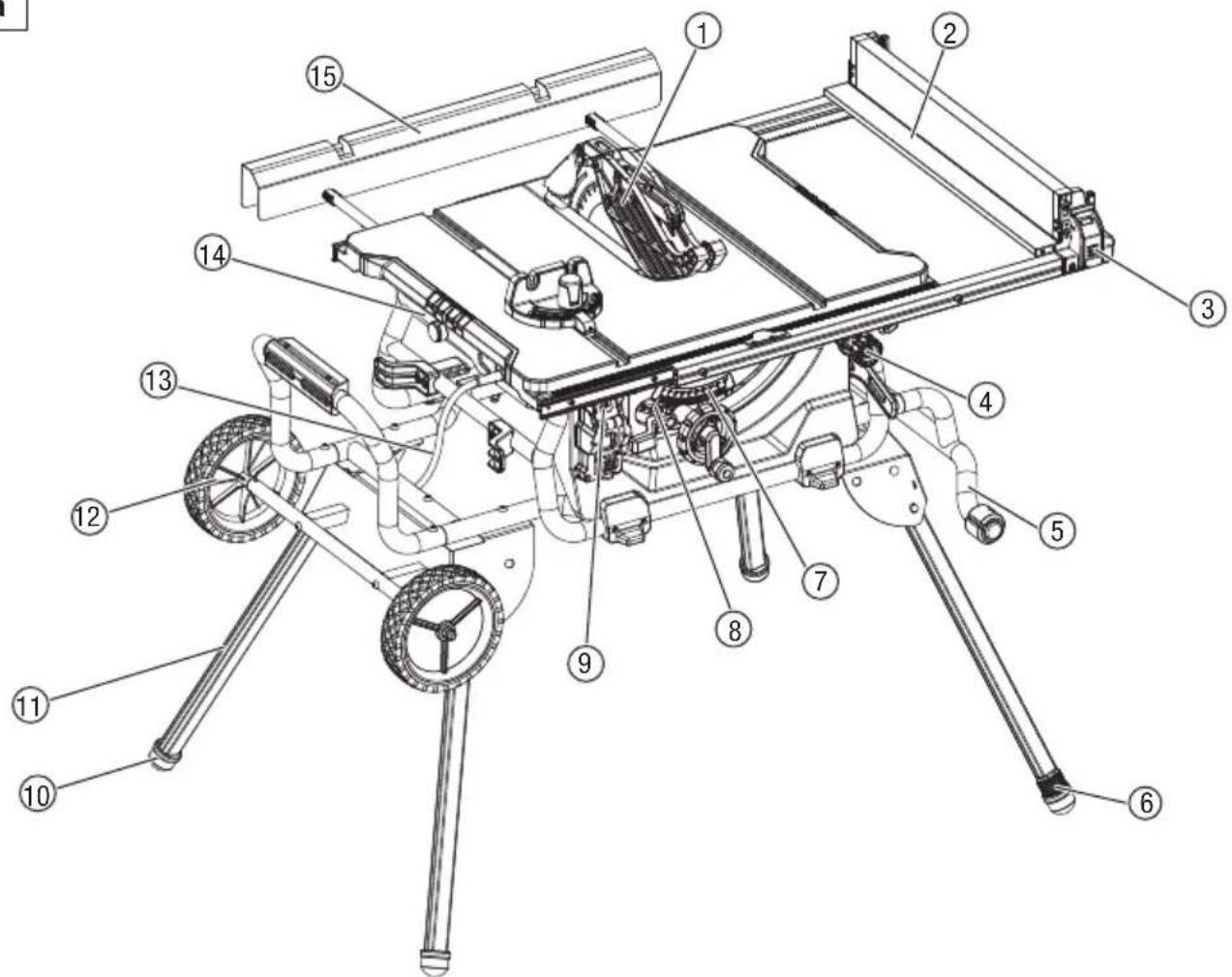
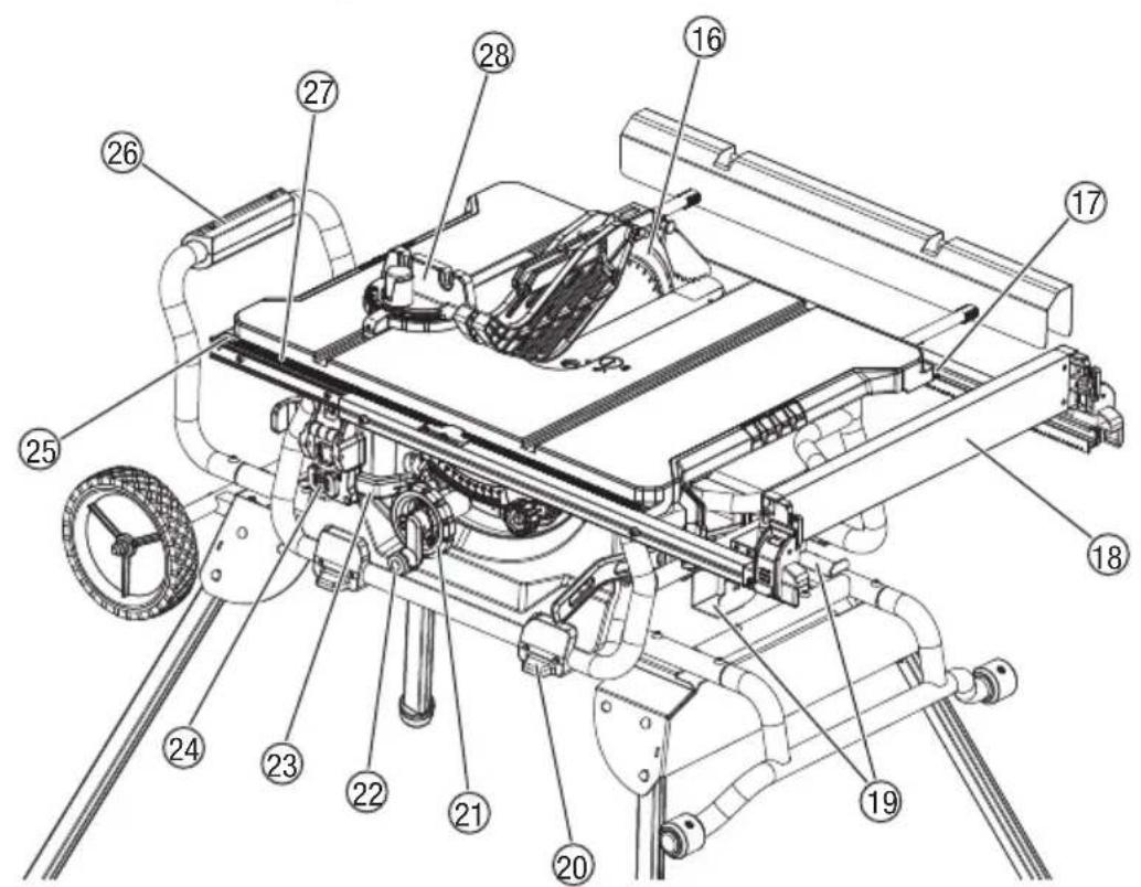
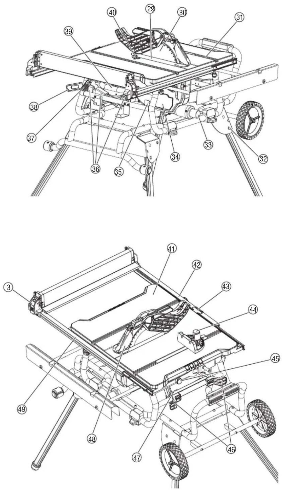
| 1 | Blade guard | 50 | Table saw assembly |
| 2 | Narrow fence | 51 | Stand assembly |
| 3 | Rip fence lock lever | 52 | Flat round head screws M8 x 45 |
| 4 | Adjusting knob | 53 | Lock nut M8 |
| 5 | Handle I | 54 | Flat round head screws M8 x 10 |
| 6 | Adjustable foot | 55 | Big flat washer 10 |
| 7 | Bevel scale | 56 | Lock nut M10 |
| 8 | Bevel indicator | 57 | Wheel shaft |
| 9 | Overload reset switch | 58 | Wheel assembly |
| 10 | Foot | 59 | Flat round head screws M8 x 100 |
| 11 | Stand leg | 60 | Set screw |
| 12 | Wheel | 61 | Riving knife lock knob |
| 13 | Power cord | 62 | Inner blade flange |
| 14 | Blade wrench | 63 | Arbour |
| 15 | Outfeed support | 64 | Arbour nut |
| 16 | Riving knife | 65 | Outer blade flange |
| 17 | Rear rail | 66 | Ring |
| 18 | Rip fence | 67 | Knob |
| 19 | Blade guard storage | 68 | Slot A |
| 20 | Foot mat | 69 | Spring pin |
| 21 | Height/bevel adjusting handwheel | 70 | Pin |
| 22 | Height adjusting knob | 71 | Hole |
| 23 | Bevel lock lever | 72 | Knob |
| 24 | Switch assembly | 73 | Pin |
| 25 | Front rail | 74 | Pin |
| 26 | Stand support assembly | 75 | Slot B |
| 27 | Scale | 76 | Slot C |
| 28 | Mitre gauge | 77 | Set screw |
| 29 | Table insert | 78 | Stop screw |
| 30 | Saw blade | 79 | Extension pole |
| 31 | Mitre gauge groove | 80 | Lock knob |
| 32 | Lock pin | 81 | Position screw |
| 33 | Dust extraction port | 82 | Slot |
| 34 | Small baffle | 83 | Guide rail |
| 35 | Anti-kickback pawls storage | 84 | Switch cover |
| 36 | Push stick storage | 85 | Switch I |
| 37 | Fence rails lock lever | 86 | Switch paddle |
| 38 | Push stick | 87 | Hole |
| 39 | Handle II | 88 | Support |
| 40 | Lock knob | 89 | Screw |
| 41 | Working table | 90 | Flat washer |
| 42 | Front fence rail | 91 | Framing square |
| 43 | Rip fence scale indicator | 92 | 90° stop set screw |
| 44 | Mitre gauge lock knob | 93 | Triangle square |
| 45 | Blade wrench storage | 94 | 45° stop set screw |
| 46 | Power cord storage | 95 | Screw |
| 47 | Mitre gauge storage | 96 | Screw |
| 48 | Anti-kickback pawls | 97 | Red pointer |
| 49 | Rear fence rail | 98 | Screw |
Deutsch
Read all safety warnings, instructions, illustrations and specifications provided with this power tool. Failure to follow all instructions listed below may result in electric shock, fire and/or serious injury.
Save all warnings and instructions for future reference.
The term “power tool” in the warnings refers to your mains-operated (corded) power tool or battery-operated (cordless) power tool.
1) Work area safety
a) Keep work area clean and well lit.
Cluttered or dark areas invite accidents.
b) Do not operate power tools in explosive atmospheres, such as in the presence of flammable liquids, gases or dust.
Power tools create sparks which may ignite the dust or fumes.
c) Keep children and bystanders away while operating a power tool.
Distractions can cause you to lose control.
2) Electrical safety
a) Power tool plugs must match the outlet. Never modify the plug in any way. Do not use any adapter plugs with earthed (grounded) power tools.
Unmodified plugs and matching outlets will reduce risk of electric shock.
b) Avoid body contact with earthed or grounded surfaces, such as pipes, radiators, ranges and refrigerators.
There is an increased risk of electric shock if your 4) body is earthed or grounded.
c) Do not expose power tools to rain or wet conditions.
Water entering a power tool will increase the risk of electric shock.
d) Do not abuse the cord. Never use the cord for carrying, pulling or unplugging the power tool. Keep cord away from heat, oil, sharp edges or moving parts.
Damaged or entangled cords increase the risk or electric shock.
e) When operating a power tool outdoors, use an extension cord suitable for outdoor use.
Use of a cord suitable for outdoor use reduce the risk of electric shock.
f) If operating a power tool in a damp location is unavoidable, use a RESIDUAL CURRENT DEVICE (RCD) protected supply.
Use of an RCD reduces the risk of electric shock.
3) Personal safety
a) Stay alert, watch what you are doing and use common sense when operating a power tool. Do not use a power tool while you are tired or under the influence of drugs, alcohol or medication.
A moment of inattention while operating power tools may result in serious personal injury.
b) Use personal protective equipment. Always wear
eye protection.
Protective equipment such as dust mask, non-skid safety shoes, hard hat, or hearing protection used for appropriate conditions will reduce personal injuries.
c) Prevent unintentional starting. Ensure the switch is in the off-position before connecting to power source and/or battery pack, picking up or carrying the tool.
Carrying power tools with your finger on the switch or energising power tools that have the switch on invites accidents.
d) Remove any adjusting key or wrench before turning the power tool on.
A wrench or a key left attached to a rotating part of the power tool may result in personal injury.
e) Do not overreach. Keep proper footing and balance at all times.
This enables better control of the power tool in unexpected situations.
f) Dress properly. Do not wear loose clothing or jewellery. Keep your hair, clothing and gloves away from moving parts.
Loose clothes, jewellery or long hair can be caught in moving parts.
g) If devices are provided for the connection of dust extraction and collection facilities, ensure these are connected and properly used.
Use of dust collection can reduce dust-related hazards.
h) Do not let familiarity gained from frequent use of tools allow you to become complacent and ignore tool safety principles.
A careless action can cause severe injury within a fraction of a second.
a) Do not force the power tool. Use the correct power tool for your application.
The correct power tool will do the job better and safer at the rate for which it was designed.
b) Do not use the power tool if the switch does not turn it on and off.
Any power tool that cannot be controlled with the switch is dangerous and must be repaired.
c) Disconnect the plug from the power source and/or remove the battery pack, if detachable, from the power tool before making any adjustments, changing accessories, or storing power tools.
Such preventive safety measures reduce the risk of starting the power tool accidentally.
d) Store idle power tools out of the reach of children and do not allow persons unfamiliar with the power tool or these instructions to operate the power tool.
Power tools are dangerous in the hands of untrained users.
e) Maintain power tools and accessories. Check for misalignment or binding of moving parts, breakage of parts and any other condition that may affect the power tool's operation. If damaged, have the power tool repaired before use.
Many accidents are caused by poorly maintained
English
power tools.
f) Keep cutting tools sharp and clean.
Properly maintained cutting tools with sharp cutting edges are less likely to bind and are easier to control.
g) Use the power tool, accessories and tool bits etc. in accordance with these instructions, taking into account the working conditions and the work to be performed.
Use of the power tool for operations different from those intended could result in a hazardous situation.
h) Keep handles and grasping surfaces dry, clean and free from oil and grease.
Slippery handles and grasping surfaces do not allow for safe handling and control of the tool in unexpected situations.
5) Service
a) Have your power tool serviced by a qualified repair person using only identical replacement parts.
This will ensure that the safety of the power tool is maintained.
SAFETY INSTRUCTIONS FOR TABLE SAW
1) Guarding related warnings
a) Keep guards in place. Guards must be in working order and be properly mounted.
A guard that is loose, damaged, or is not functioning correctly must be repaired or replaced.
b) Always use saw blade guard, riving knife and anti-kickback pawls for every through-cutting operation.
For through-cutting operations where the saw blade cuts completely through the thickness of the workpiece, the guard and other safety devices help reduce the risk of injury.
c) Immediately reattach the guarding system after completing an operation (such as rabbeting) which requires removal of the guard, riving knife and/or anti-kickback pawls.
The guard, riving knife, and anti-kickback pawls help to reduce the risk of injury.
d) Make sure the saw blade is not contacting the guard, riving knife or the workpiece before the switch is turned on.
Inadvertent contact of these items with the saw blade could cause a hazardous condition.
e) Adjust the riving knife as described in this instruction manual.
Incorrect spacing, positioning and alignment can make the riving knife ineffective in reducing the likelihood of kickback.
f) For the riving knife and anti-kickback pawls to work, they must be engaged in the workpiece.
The riving knife and anti-kickback pawls are ineffective when cutting workpieces that are too short to be engaged with the riving knife and anti-kickback pawls.
Under these conditions a kickback cannot be prevented by the riving knife and anti-kickback pawls.
g) Use the appropriate saw blade for the riving
knife.
For the riving knife to function properly, the saw blade diameter must match the appropriate riving knife and the body of the saw blade must be thinner than the thickness of the riving knife and the cutting width of the saw blade must be wider than the thickness of the riving knife.
- Safety instructions for sawing procedures
a) ⚠️DANGER: Never place your fingers or hands in the vicinity or in line with the saw blade.
A moment of inattention or a slip could direct your hand towards the saw blade and result in serious personal injury.
b) Feed the workpiece into the saw blade only against the direction of rotation.
Feeding the workpiece in the same direction that the saw blade is rotating above the table may result in the workpiece, and your hand, being pulled into the saw blade.
c) Never use the mitre gauge to feed the workpiece when ripping and do not use the rip fence as a length stop when cross cutting with the mitre gauge.
Guiding the workpiece with the rip fence and the mitre gauge at the same time increases the likelihood of saw blade binding and kickback.
d) When ripping, always apply the workpiece feeding force between the fence and the saw blade. Use a push stick when the distance between the fence and the saw blade is less than 150 mm, and use a push block when this distance is less than 50 mm.
Work helping" devices will keep your hand at a safe distance from the saw blade.
e) Use only the push stick provided by the manufacturer or constructed in accordance with the instructions.
The push stick provides sufficient distance of the hand from the saw blade.
f) Never use a damaged or cut push stick.
A damaged push stick may break causing your hand to slip into the saw blade.
g) Do not perform any operation "freehand". Always use either the rip fence or the mitre gauge to position and guide the workpiece.
"Freehand" means using your hands to support or guide the workpiece, in lieu of a rip fence or mitre gauge.
Freehand sawing leads to misalignment, binding and kickback.
h) Never reach around or over a rotating saw blade.
Reaching for a workpiece may lead to accidental contact with the moving saw blade.
i) Provide auxiliary workpiece support to the rear and/or sides of the saw table for long and/or wide workpieces to keep them level.
A long and/or wide workpiece has a tendency to pivot on the table's edge, causing loss of control, saw blade binding and kickback.
j) Feed workpiece at an even pace. Do not bend or twist the workpiece. If jamming occurs, turn the tool off immediately, unplug the tool then clear
the jam.
Jamming the saw blade by the workpiece can cause kickback or stall the motor.
k) Do not remove piece of cut-off material while the saw is running.
The material may become trapped between the fence or inside the saw blade guard and the saw blade pulling your fingers into the saw blade. Turn the saw off and wait until the saw blade stops before removing material.
I) Use an auxiliary fence in contact with the table top when ripping workpieces less than 2 mm thick.
A thin workpiece may wedge under the rip fence and create a kickback.
Kickback is a sudden reaction of the workpiece due to a pinched, jammed saw blade or misaligned line of cut in the workpiece with respect to the saw blade or when a part of the workpiece binds between the saw blade and the rip fence or other fixed object.
Most frequently during kickback, the workpiece is lifted from the table by the rear portion of the saw blade and is propelled towards the operator.
Kickback is the result of saw misuse and/or incorrect operating procedures or conditions and can be avoided by taking proper precautions as given below.
a) Never stand directly in line with the saw blade. Always position your body on the same side of the saw blade as the fence rail.
Kickback may propel the workpiece at high velocity towards anyone standing in front and in line with the saw blade.
b) Never reach over or in back of the saw blade to pull or to support the workpiece.
Accidental contact with the saw blade may occur or kickback may drag your fingers into the saw blade.
c) Never hold and press the workpiece that is being cut off against the rotating saw blade.
Pressing the workpiece being cut off against the saw blade will create a binding condition and kickback.
d) Align the fence to be parallel with the saw blade. A misaligned fence will pinch the workpiece against the saw blade and create kickback.
e) Use a featherboard to guide the workpiece against the table and fence when making non-through cuts such as rabbeting.
A featherboard helps to control the workpiece in the event of a kickback.
f) Use extra caution when making a cut into blind areas of assembled workpieces.
The protruding saw blade may cut objects that can cause kickback.
g) Support large panels to minimise the risk of blade pinching and kickback.
Large panels tend to sag under their own weight. Support(s) must be placed under all portions of the panel overhanging the table top.
h) Use extra caution when cutting a workpiece that is twisted, knotted, warped or does not have a straight edge to guide it with a mitre gauge or
along the fence.
A warped, knotted, or twisted workpiece is unstable and causes misalignment of the kerf with the saw blade, binding and kickback.
i) Never cut more than one workpiece, stacked vertically or horizontally.
The saw blade could pick up one or more pieces and cause kickback.
j) When restarting the saw with the saw blade in the workpiece, centre the saw blade in the kerf so that the saw teeth are not engaged in the material.
If the saw blade binds, it may lift up the workpiece and cause kickback when the saw is restarted.
k) Keep saw blades clean, sharp, and with sufficient set. Never use warped saw blades or saw blades with cracked or broken teeth.
Sharp and properly set saw blades minimise binding, stalling and kickback.
- Table saw operating procedure warnings
a) Turn off the table saw and disconnect the power cord when removing the table insert, changing the saw blade or making adjustments to the riving knife, anti-kickback pawls or saw blade guard, and when the machine is left unattended.
Precautionary measures will avoid accidents.
b) Never leave the table saw running unattended. Turn it off and don't leave the tool until it comes to a complete stop.
An unattended running saw is an uncontrolled hazard.
c) Locate the table saw in a well lit and level area where you can maintain good footing and balance. It should be installed in an area that provides enough room to easily handle the size of the workpieces.
Cramped, dark areas, and uneven slippery floors invite accidents.
d) Frequently clean and remove sawdust from under the saw table and/or the dust collection device.
Accumulated saw dust is combustible and may self ignite.
e) The table saw must be secured.
A table saw that is not properly secured may move or tip over.
f) Remove tools, wood scraps, etc. from the table before the table saw is turned on.
Distraction or a potential jam can be dangerous.
g) Always use saw blades with correct size and shape (diamond versus round) of arbour holes.
Saw blades that do not match the mounting hardware of the saw will run off-centre, causing loss of control.
h) Never use damaged or incorrect saw blade mounting means such as flanges, saw blade washers, bolts or nuts.
These mounting means were specially designed for your saw, for safe operation and optimum performance.
i) Never stand on the table saw, do not use it as a stepping stool. Serious injury could occur if the tool is tipped or if the cutting tool is accidentally contacted.
English
j) Make sure that the saw blade is installed to rotate in the proper direction. Do not use grinding wheels, wire brushes, or abrasive wheels on a table saw.
Improper saw blade installation or use of accessories not recommended may cause serious injury.
k) Only use 10" saw blade with kerf width of 2.8mm and blade body thickness is 1.8 mm match the riving knife with thickness of 2.3 mm.
I) Always use only a saw blade diameter in accordance with the markings on the saw; Use only saw blades for which the maximum possible speed is not less than the maximum spindle speed of the product.
m) Do not use any blunt, cracked, deformed or damaged saw blades. Only replace the saw blade with one complying with the European standard EN 847-1.
5. Additional safety instructions
- Please also observe the special safety instructions in the respective chapters.
- Where applicable, follow the legal directives or regulations for the prevention of accidents pertaining to the use of table saws.
- Avoid overheating of the saw teeth.
- Do not attempt to stop the saw blade by pushing the workpiece against its side.
- Store saw blade in such manner that nobody will get hurt.
- Before making a cut, be sure all adjustments are secure.
- Be sure blade path is free of nails. Inspect for and remove all nails from lumber before cutting.
- Never touch blade or other moving parts during use.
- Make sure the work area has ample lighting to see the work and that no obstructions will interfere with safe operation before performing any work using the table saw.
- If this saw makes an unfamiliar noise or if it vibrates excessively, cease operating immediately, turn unit off and unplug the tool until the problem has been located and corrected. Contact a HiKOKI Authorized Service Center if the problem can not be found.
GLOSSARY OF TERMS
The safe use of this product requires an understanding of the information on the tool and in this operator's manual as well as a knowledge of the project you are attempting. Before use of this product, familiarize yourself with all operating features and safety rules.
Anti-kickback Pawls
Kickback is a hazard in which the workpiece is thrown back toward the operator. The teeth on the anti-kickback pawls point away from the workpiece. If the workpiece should be pulled back toward the operator, the teeth dig into the wood to help prevent or reduce the possibility of kickback.
Bevel Scale
The easy-to-read scale on the front of the cabinet shows the exact blade angle.
Blade
For maximum performance, it is recommended that you use the 40-tooth, 254 mm carbide tipped combination blade.provided with your saw. The blade is raised and lowered with the height/bevel adjusting handwheel. Bevel angles are locked with the bevel lock lever.
WARNING
Do not use blades rated less than the speed of this tool. Failure to heed this warning could result in personal injury.
WARNING
Be careful of your hand. Blade are sharp. Wear work gloves when removing or installing blades.
Blade Guard
Always keep the guard down over the blade for through sawing cuts.
Bevel Lock Lever
This lever under the working table surface on the front of the cabinet, locks the angle setting of the blade.
Height/Bevel Adjusting Handwheel
Located on the front of the cabinet, this handwheel is used to lower and raise the blade for adjustments or blade replacement. The handwheel also makes the adjustment for bevel angles easy.
Fence Rails Lock Lever
The lever under working table surface on the right of the saw releases the fence rails or locks it in place.
Adjusting Knob
This knob is under the working table surface on the front of the saw. Turn it clockwise will slide the fence rails to right. Turn it counter-clockwise will slide fence rails to left.
Outfeed Support
The outfeed support at the back of the tool gives the operator additional support when cutting long workpieces.
Mitre Gauge
The mitre gauge aligns the wood for a cross cut. The easy-to-read indicator shows the exact angle for a mitre cut, with positive stops at 0^ , 22.5^ and 45^ .
Mitre Gauge Grooves
The mitre gauge rides in these grooves on either side of the blade.
Front Rail
Front rail provides support for the front fence rail and rip fence.
Rip Fence with a Narrow Fence
A sturdy metal fence guides the workpiece and It can be fixed on three positions of the fence rails with rip fence lock levers secure in place, the narrow fence can supports workpiece hat extends beyond the working table.
Scale
Located on the front rail, the easy-to-read scale provides precise measurements for rip cuts.
Riving Knife
A metal piece, slightly thinner than the saw blade, which helps keep the kerf open and prevent kickback.
Arbor
The shaft on which a blade or cutting tool is mounted.
Overload Reset Switch
The saw is equipped with the overload reset switch to prevent the saw from overload damage. The saw will automatically shut off if the machine was with overloaded cutting or low voltage. Wait for
the motor to cool down for at least five minutes. And press the overload reset switch button to resume the overload switch. After the motor has cooled down, press the green "I"-button on the ON/OFF switch to restart saw.
Working table
Surface where the workpiece rests while performing a cutting operation.
Kerf
The material removed by the blade in a through-cut, or the slot produced by the blade in a nonthrough or partial cut.
Push Stick
A push stick should be used for narrow ripping operations when the fence is 150 mm or less from the blade. These aids help to keep the operator's hands well away from the blade.
Kickback
A hazard that can occur when the blade binds or stalls, throwing the workpiece back toward the operator.
Ripping or Rip Cut
A cutting operation along the length of the workpiece.
Bevel Cut
A cutting operation made with the blade at any angle other than 90^ to the table surface.
Compound Cut
A crosscut made with both a mitre angle and a bevel angle.
Crosscut
A cutting or shaping operation made across the grain or width of the workpiece.
Mitre Cut
A cutting operation made with the workpiece at any angle other than 90^ to the blade.
Non-Through Cut
Any cutting operation where the blade does not extend completely through the thickness of the workpiece.
Through-sawing
Any cutting operation where the blade extends completely through the thickness of the workpiece.
Freehand
Performing a cut without the workpiece being guided by a fence, mitre gauge, or other aid Never perform any cut freehand with this saw.
SYMBOLS
WARNING
The following show symbols used for the machine. Be sure that you understand their meaning before use.
 | C 10RJ (X): Table saw |
 | To reduce the risk of injury, user must read instruction manual. |
 | Always wear eye protection. |
 | Always wear hearing protection. |
 | Danger keep hands away from blade. |
 | Never operate the tool in a damp or wet environment. |
 | Lock / to tighten or secure. |
 | Unlock / to loosen. |
 | Caution, Warning or Danger. |
| V | Volts |
| Hz | Hertz |
| A | Amperes |
| No | No load speed |
| ---/min | Revolutions per minute |
| W | Input power |
| kg | Kilogram |
| Decibel (A-rated)dB(A) |
| ~ | Alternating current |
 | Class II Construction |
 | The product complies with the applicable European directives and an evaluation method of conformity for these directives was done. |
 | Only for EU countries.Do not dispose of electric tools together with household waste material!In observance of European Directive 2012/19/EU on waste electrical and electronic equipment and its implementation in accordance with national law, electric tools that have reached the end of their life must be collected separately and returned to an environmentally compatible recycling facility. |
SPECIFICATIONS
| 220-240V~, 50HzInput Voltage |
| 1500WPower Input |
| 4500/minNo Load Speed No |
| ø254mm × ø30mm × 2.8mm, 40TBlade Size |
| 0°~45°Bevel Range |
| 730mm x 559mmWorking Table Size |
| 730mm x 50mmOutfeed Support Size |
| 79mmMax. cutting depth at 0° |
| 57mmMax. cutting depth at 45° |
| 440mmMax. rip to left to blade |
| 880mmMax. rip to right to blade |
| II/Protection class |
| 44kgWeight |
| 94.8 dB(A)Sound pressure level LpA |
| 107.8 dB(A)Sound power level LwA |
| 3 dB(A)Uncertainty KpA, KwA |
The sound emission values have been obtained according to the noise test code given in EN 62841-1 and EN 62841-3-1. The noise for the operator may exceed 80 dB(A) and ear protection measures are necessary.
LOOSE PARTS
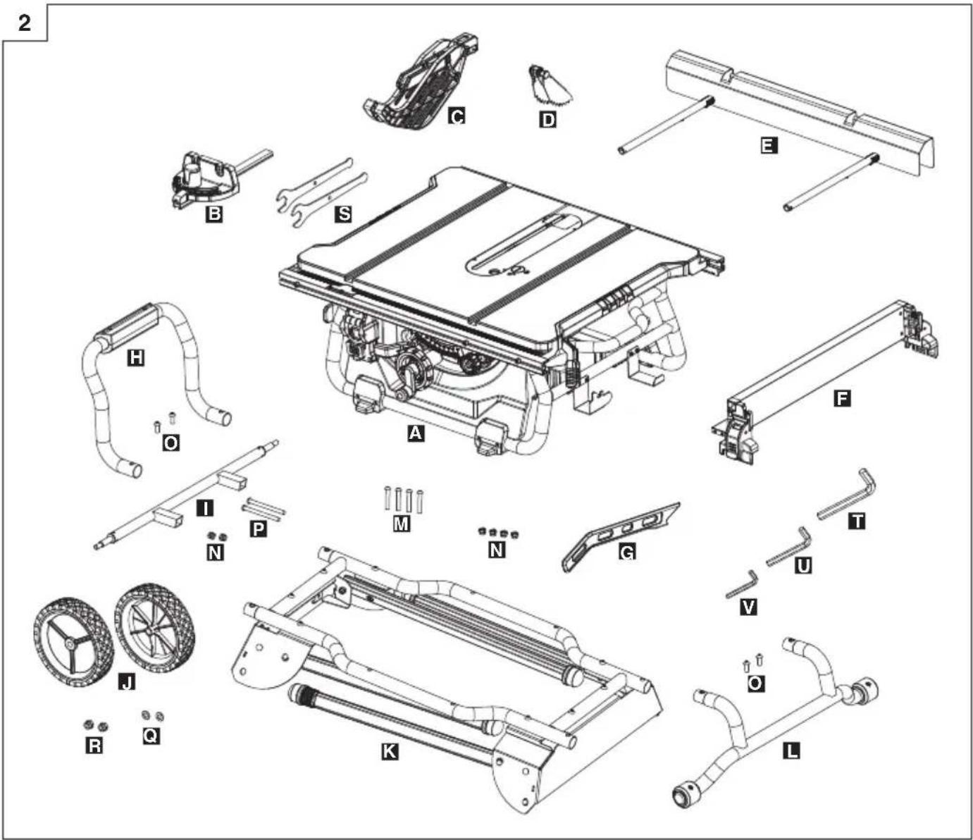
The following items are included with your table saw: (Fig. 2)
A: Table saw assembly 1
B: Mitre gauge (in stored position) 1
C: Blade guard assembly (in stored position) 1
D: Anti-kickback pawls assembly (in stored position) ..... 1
E: Outfeed support assembly 1
F: Rip fence assembly (in stored position) 1
G: Push stick (in stored position) 1
H: Stand support assembly 1
I: Wheel shaft 1
J: Wheel 2
K: Stand assembly 1
L: Handle I assembly 1
M: Flat round head screws M8 x 45 .... 4
N: Lock nut M8 6
O: Flat round head screws M8 x 10 4
P: Flat round head screws M8 x 100 ...... 2
Q: Big flat washer 10 2
R: Lock nut M10 2
S: Blade wrench 2
T: 5mm Hex key .... 1
U: 4mm Hex key .... 1
V: 2.5mm Hex key 1
ASSEMBLY
1. Unpacking your table saw
This product requires assembly.
- Carefully lift saw from the carton and place it on a level work surface.
- Inspect the tool carefully to make sure that no breakage or damage occurred during shipping.
Do not discard the packing material until you have carefully inspected and satisfactorily operated the tool.
The saw is factory set for accurate cutting. After assembling it, check for accuracy. If shipping has influenced the settings, refer to specific procedures explained in this Operator's Manual.
☐ If any part is missing or damaged, do not attempt to assemble the table saw, plug in the power cord, or turn the switch ON until the missing or damaged part is obtained and is installed correctly.
CAUTION
This tool is heavy. To avoid back injury, lift with your legs,
not your back, and get help when needed.
WARNING
Remove the protective polyfoam from between the saw's housing and the motor.
WARNING
The use of attachments or accessories not listed in this manual might be hazardous and could cause serious personal injury.
WARNING
Do not attempt to modify this tool or create accessories not recommended for use with this tool. Any such alteration or modification is misuse, and could result in a hazardous condition leading to possible serious personal injury.
WARNING
Do not connect to the power supply until assembly is complete. Failure to comply could result in accidental starting and possible serious personal injury.
WARNING
Always make sure the table saw is securely mounted to the stand. Failure to heed this warning can result in serious personal injury.
2. You will need
Items not supplied
- Flat head screwdriver
- Screwdriver
- 13mm wrench / Adjustment wrench
- Framing square
○ Triangle square
Items supplied
- Blade wrench (2 pc)
- 2.5mm Hex key (1 pc)
- 4mm Hex key (1 pc)
- 5mm Hex key (1 pc)
WARNING
To avoid injury, do not connect this table saw to a power source until it is completely assembled and adjusted and you have read and understood the operator's manual.
CAUTION
Many of the illustrations in this manual show only portions of the table saw. This is intentional so that we can clearly show points being made in the illustrations. Never operate the saw without all guards securely in place and in good operating condition.
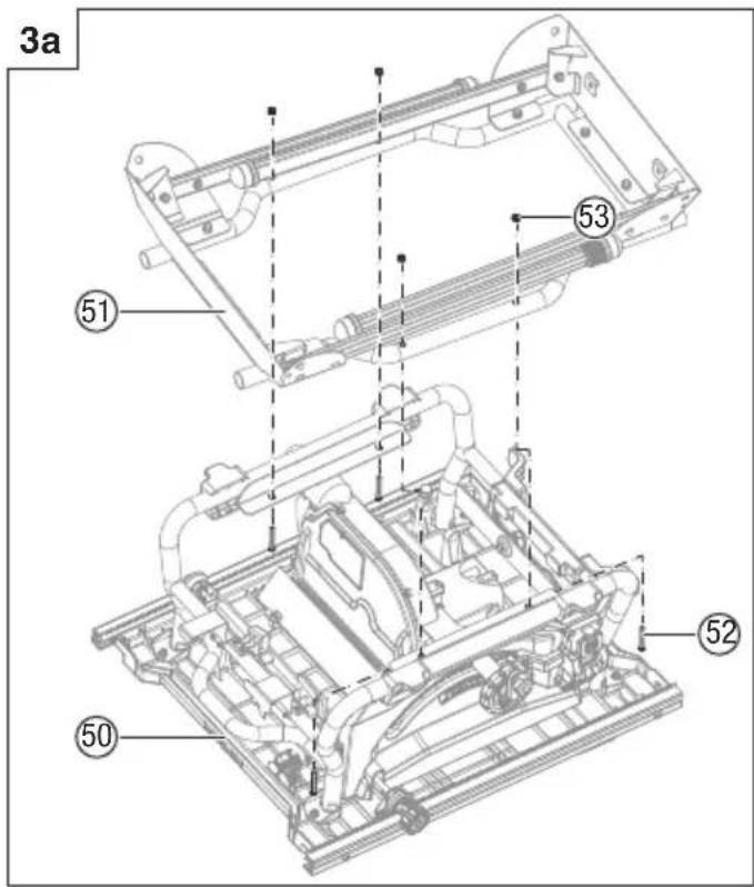
3. Assemble the stand (Fig. 3a-3e)
- Place cardboard or an old blanket on floor in order to protect the surface of the working table.
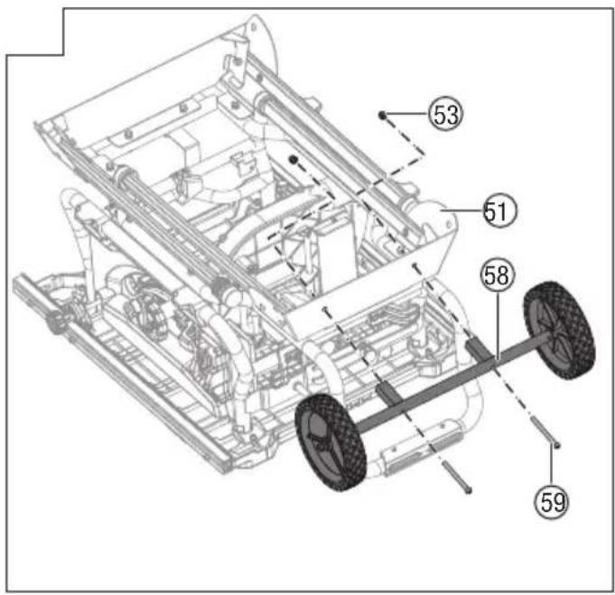
- Place the table saw assembly (50) upside down on the protective material.
○ Attach the stand assembly (51) to the table saw assembly (50) with four flat round head screws M8 x 45 (52) and four lock nut M8 (53) (two holes on the side board of the stand assembly located on the blade wrench storage). (Fig. 3a)
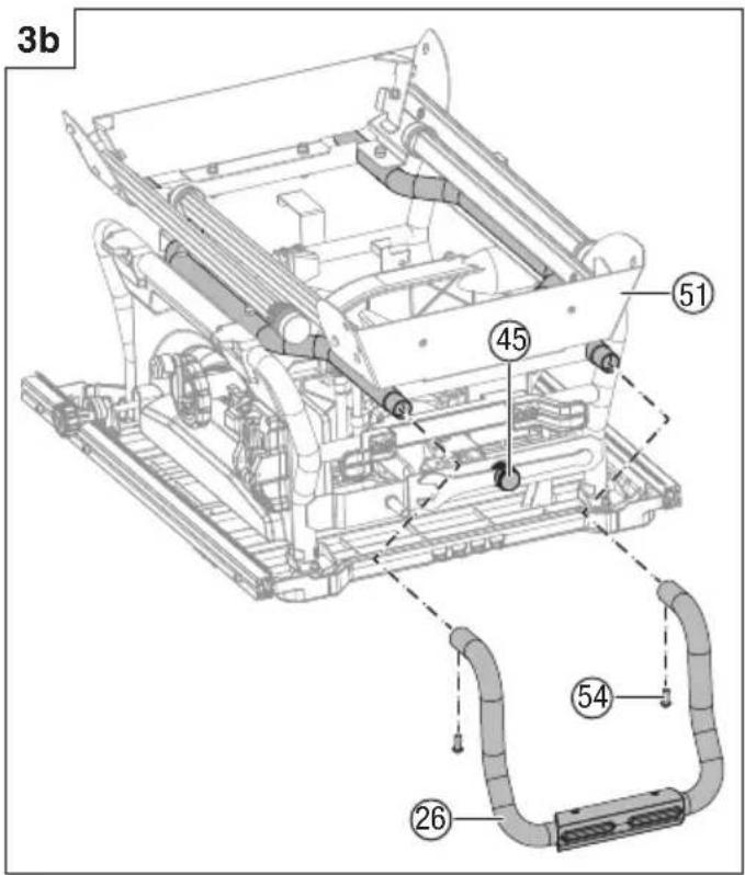
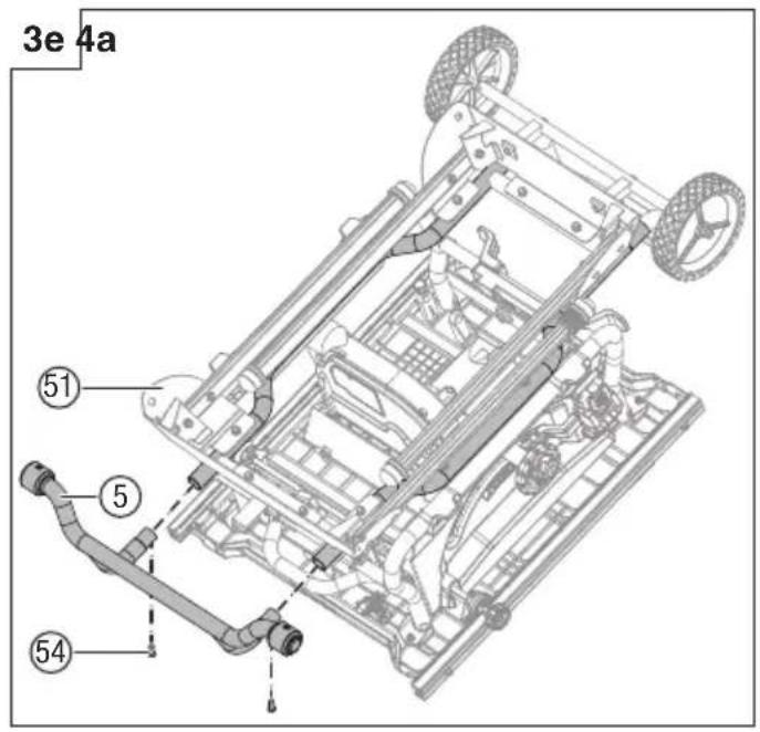
- Attach the tubes of the stand support assembly (26) with the corresponding tubes (located on side of blade wrench storage (45)) on the stand assembly (51) and align the holes. Insert the flat round head screws M8 x 10 (54) into the hole and tighten with 5mm hex key. (Fig. 3b)
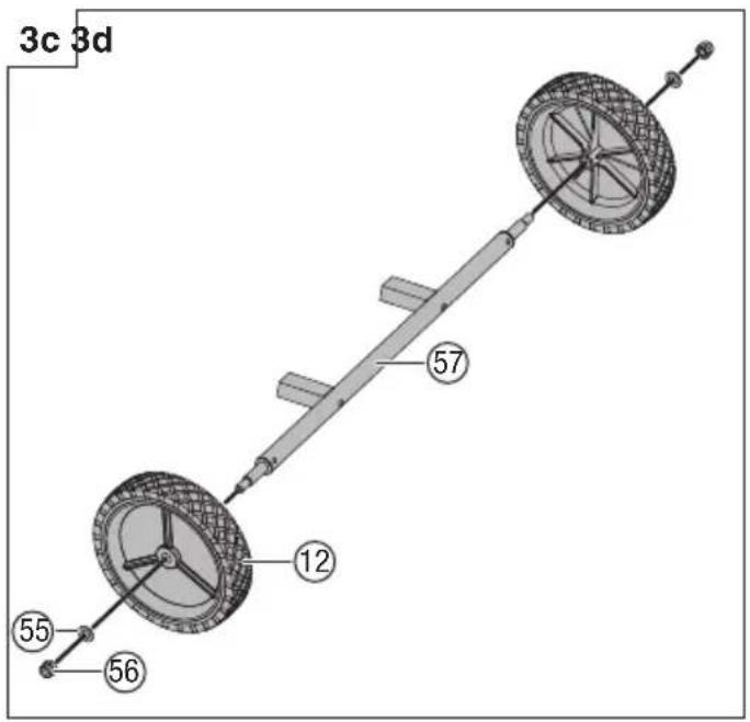
☐ Slide one wheel (12), one big flat washer 10 (55) and one lock nut M10 (56) onto the wheel shaft (57), secure wheel in place by tightening the lock nut M10. Repeat with the second wheel. (Fig. 3c)
○ Attach the wheel assembly (58) to the stand assembly (51) with two flat round head screws M8 x 100 (59) and two lock nut M8 (53). (Fig. 3d)
○ Attach the tubes of the handle I assembly (5) with the corresponding tubes (located on side of blade guard storage) on the stand assembly (51) and align the holes. Insert the flat round head screws M8 x 10 (54) into the hole and tighten with 5 mm hex key. (Fig. 3e)
4. Open the stand (Fig. 4a-4d)
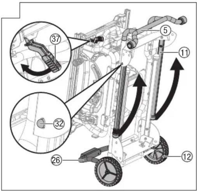
- Push the fence rails lock lever (37) toward the front of the saw to lock it. (Fig. 4a)
Grasp the handle I (5) and tilt saw back onto wheels until the stand is balanced on the wheels (12) and stand support assembly (26). (Fig. 4a)
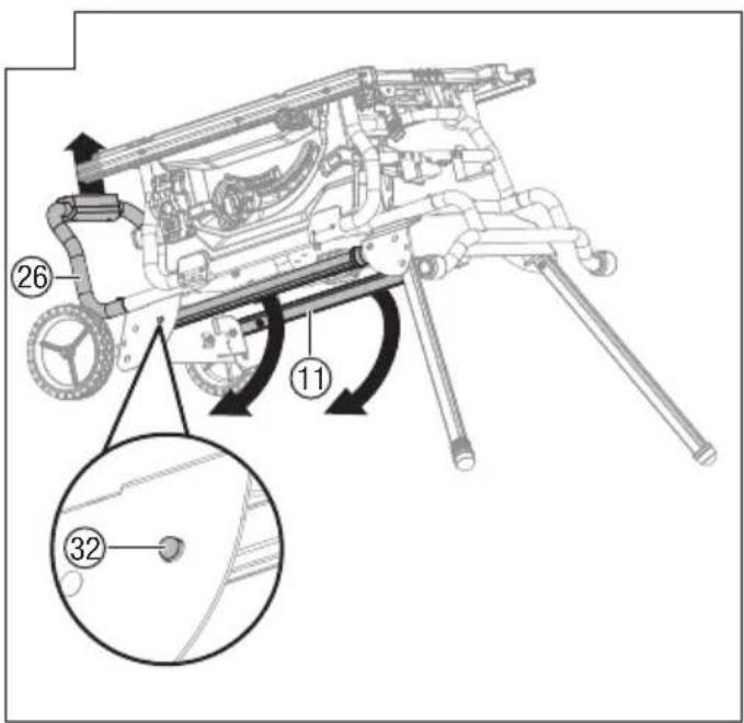
- Fold out two upper stand legs (11) (located on side of the handle I). To do this, push the lock pins (32) until
they unlock the stand legs (11) from the holes, then swing the stand legs (11) upward until the stand legs (11) are locked with the lock pins (32) engage the holes.(Fig. 4a)
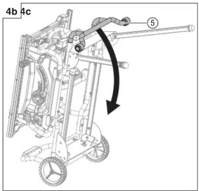
- Grasp the handle I (5) firmly and slowly tilt saw downward until the saw is balanced on the ground. (Fig. 4b-4c)
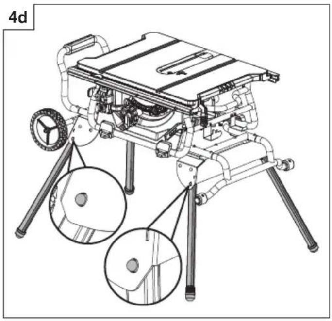
Grasp the stand support assembly (26) and lift it up until two other stand legs (11) leaving off the ground, then fold out two stand legs (11). To do this, push the lock pins (32) until they unlock the stand legs (11) from the holes, then swing the stand legs (11) downward until the stand legs are locked with the locki pins (32) engage the holes. (Fig. 4c) Make sure the table saw is balanced with four leg stands stand on the floor.
Fig. 4d is the leg stand assembly in an open position.
WARNING
Keep your fingers clear of the hinge points while opening the stand. Danger of fingers being crushed or contused.
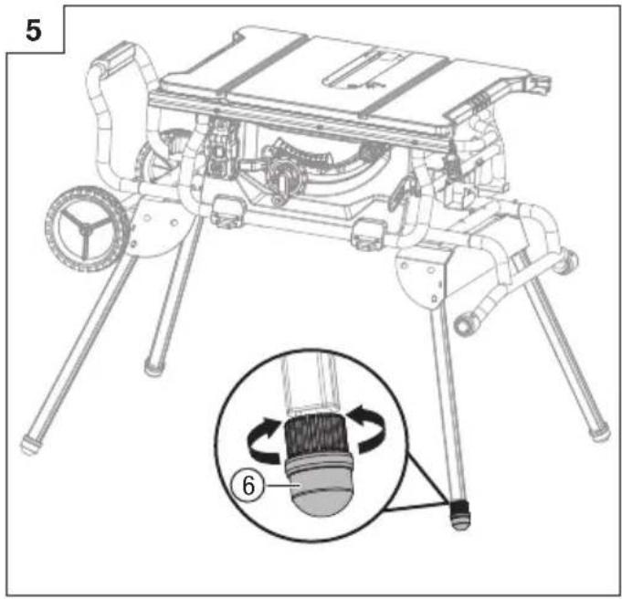
5. To secure/level the stand (Fig. 5)
With the stand open, resting on a level surface, the stand should not move or rock from side to side. If the stand rocks from side to side, the adjustable foot (6) need adjusting until the stand is balanced.
- Lift the stand slightly so that you may turn the adjustable foot (6) until the stand no longer rocks.
- Turning clockwise will lower the foot.
- Turning counter-clockwise will raise the foot.
WARNING
The table saw must be secured. A table saw that is not properly secured may move or tip over.
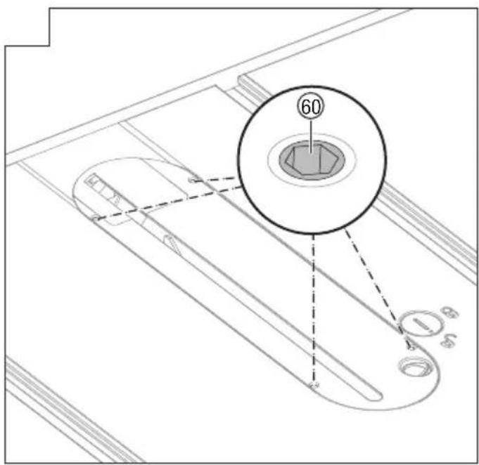
6. To remove/replace/align the table insert (Fig. 6a-6b) WARNING
The table insert must be level with the saw table. If the table insert is too high or too low, the workpiece can catch on the uneven edges, resulting in binding or kickback, which could result in serious personal injury.
WARNING
Be care of your hands avoided to be spiked with the saw blade which could result in serious personal injury when removing or reinstalling the table insert.
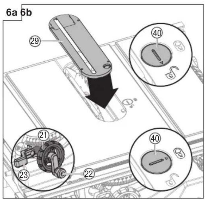
- Lower the blade all the way to down position by turning the height adjusting knob (22) counter-clockwise.
- Lock the blade by turning bevel lock lever (23) clockwise.
To remove the table insert: Turn the lock knob (40) counter-clockwise with blade wrench or flat head screwdriver to unlock the table insert (29). Place your index finger in the hole, pulling the table insert (29) out toward the front of the saw.
To reinstall the table insert: Push the table insert (29) down, turn the lock knob (40) clockwise to lock the table insert in place.
When the table insert is not level with the saw table, using a 2.5 mm hex key (supplied), adjust the four set screws (60) pre-assembled to the table located on the four holes of the table insert until the table insert is level with the working table.
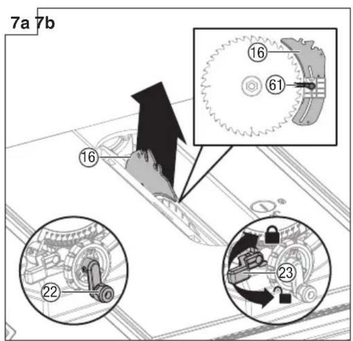
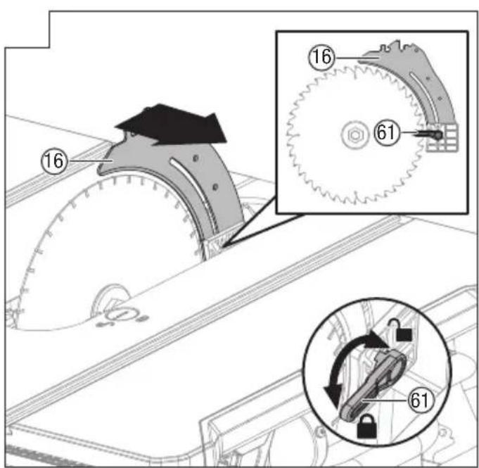
7. To install the riving knife (Fig. 7a-7b)
CAUTION
This saw is shipped with riving knife in "MIDDLE" position. Riving knife must be placed in uppermost position to attach anti-kickback pawls and blade guard for all through
English
cut operations. The "MIDDLE" position is for non-through cuts (with blade guard and anti-kickback pawls removed).
Through cutting riving knife installation
- Unplug the saw.
- Remove the table insert.
- Set the saw blade angle to 0°.
- Raise the saw blade to the uppermost position by turning the height adjusting knob (22) clockwise.
- Lock the blade by turning bevel lock lever (23) clockwise.
- Unlock riving knife lock knob (61) by turning it clockwise.
- Grasp the riving knife (16) and pull toward right side of saw to release it from spring-loaded lock pin.
- Position the riving knife in the uppermost position with springloaded lock pin is re-engaged.
- Lock the riving knife lock knob (61) by turning it counter-clockwise.
- Reinstall the table insert.
WARNING
Be extremely careful when adjust the riving knife position.
Do not allow hands to contact blade.
To place riving knife in middle position, refer to the above procedure.
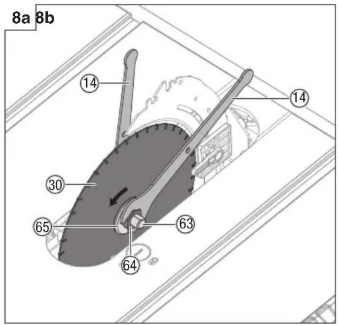
8. Removing and installing the blade (Fig. 8a-8b)
CAUTION
Check the arbor hole diameter of the blade before installing the blade. Always use the correct ring for the arbor hole of the blade you intend to use.
CAUTION
To work properly, the saw blade teeth must point down toward the front of the saw. Failure to heed this instruction could cause damage to the saw blade, the saw or the workpiece.
WARNING
Make sure that the saw blade is installed to rotate in the proper direction. Do not use grinding wheels, wire brushes, or abrasive wheels on a table saw. Improper saw blade installation or use of accessories not recommended may cause serious injury.
WARNING
Only use a 254 mm diameter blade. To avoid injury from an accidental start, make sure the switch is in the OFF position and the plug is not connected to the power source outlet.
- Unplug the saw.
- Turn height adjustment knob clockwise to raise blade to maximum height.
- Remove the table insert.
- Set the saw blade angle to 0^ and raise the saw blade to the uppermost position.
- Remove the blade wrenches from storage area.
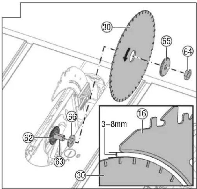
Remove the blade:
○ Using one opened-ended blade wrench (14), place the flat open end on the flats on the inner blade flange (62).
○ Using the other opened-ended blade wrench (14), place the flat open end on the flats on the arbor nut (64). Holding both wrenches firmly, pull the opened-ended blade wrench on the arbor nut (64) forward to the front of the machine.
- Remove arbor nut (64), outer blade flange (65), saw
blade (30) and ring (66).
WARNING
Be extremely careful when loosening arbor nut. Keep firm grasp on both wrenches. Do not allow hands to slip and contact blade.
Install the blade:
Place the ring (66) and one new blade on arbor (63). Make sure saw blade teeth point down at the front side of saw table. Place outer blade flange (65) and arbor nut (64) on arbor and use blade wrenches to tighten nut securely. DO NOT over tighten.
CAUTION:
The ring 30 mm in outer diameter is factory-installed onto the arbor
WARNING
The large, flat surface of the outer blade flange faces the saw blade and the saw blade (30) is firmly seated against the inner blade flange (62).
WARNING
The saw blade (30) should be aligned with the riving knife (16) and ensuring there is a gap of 3 to 8 mm between the blade teeth and the riving knife (16).
- Lower the saw blade to lowest position and replace table insert.
WARNING
If the inner blade flange has been removed, reinstall it before placing the saw blade on arbor. Failure to do so could cause an accident.
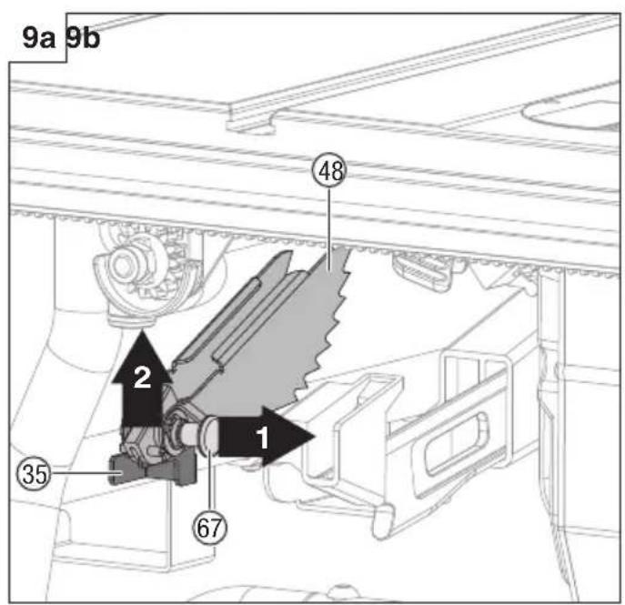
9. Anti-kickback pawls installation (Fig. 9a-9b)
Anti-kickback pawls should only be installed for through cuts.
WARNING
Make sure the anti-kickback pawls are reinstalled immediately after finishing any non-through cut operations which require their removal.
WARNING
Replace dull or damaged anti-kickback pawls. Dull or damaged anti-kickback pawls may not stop a kickback, increasing the risk of serious personal injury.
- Unplug the saw.
- Set the blade angle to 0°.
- Raise the saw blade to maximum height by turning height adjusting knob clockwise.
- Lock the blade by turning bevel lock lever clockwise.
- Place the riving knife in the highest position.
○ Pull out and hold knob (67) and push anti-kickback pawls up, remove it from the anti-kickback pawls storage (35) located on inside of the left side of saw. (Fig. 9a)
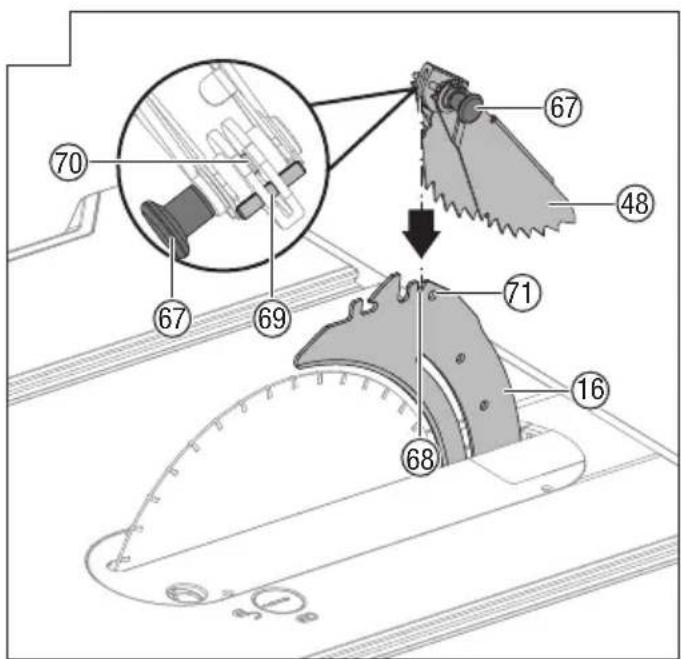
☐ Pull out and hold knob (67). Align slot in anti-kickback pawls (48) over the slot A (68) indicated of riving knife (16). Place the spring pin (69) on the anti-kickback pawls (48) into the slot A (68) indicated on the riving knife (16).
Press anti-kickback pawls (48) down until it snaps into place and release knob (67) to insert the pin (70) into hole (71) indicated on the riving knife (16).
CAUTION
Pull up on anti-kickback pawl assembly to make sure it is secured to riving knife.
WARNING
Gently pull up the anti-kickback pawls to ensure it is
locked into place. Make sure that the anti-kickback pawls move freely and are not stuck in the table insert slot.
WARNING
Use extra caution when cutting wood products having slippery surface as the anti-kickback pawls may not always be effective.
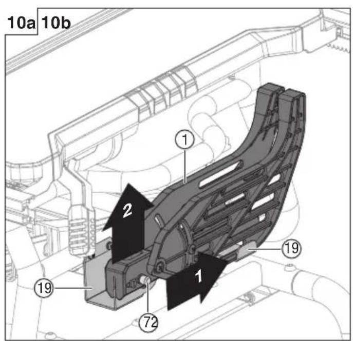
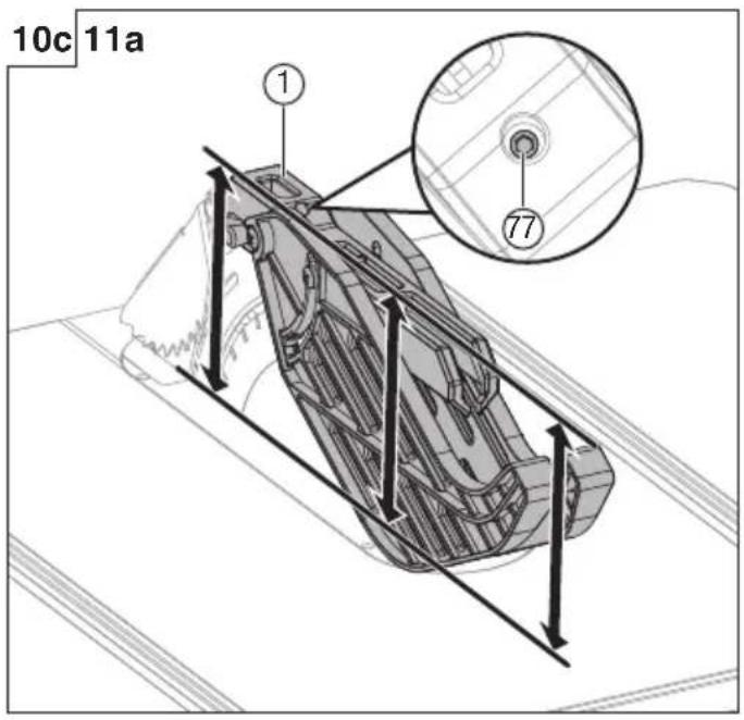
10. Blade guard installation (Fig. 10a-10c)
WARNING
KEEP GUARDS IN PLACE and in good working order for all through cut operations. Reinstall the blade guard immediately after finishing any non-through cut operations which require removal of the blade guard. Failure to heed this instruction could result in serious personal injury.
- Unplug the saw.
Hold the knobs (72) (one on either side of the blade guard) and push the knobs forward to the front of the blade guard and up until the pin comes out from the slot in the mounting bracket (blade guard storage) (19) at bottom front right side of the saw, then remove the blade guard from the U-bracket (blade guard storage) (19) at bottom middle right side of the saw (Fig. 10a).
Hold and push knobs (72) forward to the front of the blade guard. Place the pins (73, 74) on the blade guard (1) into the slot B (75) and slot C (76) indicated on theriving knife (16). (Fig. 10b)
- Pull blade guard fully back onto riving knife. Push pin and release it to lock guard into position.
○ If blade guard is not parallel to table when riving knife is in uppermost position (through cuts), adjust the set screw (77) as necessary. (Fig. 10c)
WARNING
After the installation, check the blade guard to ensure that it is properly placed and workable before operation the saw.
WARNING
When using the blade guard, lift the left and right blade guard and make sure that they move independently and contact the table surface. The blade guard can be raised to adjust the cut line, but must be lowered to contact the table surface before starting the saw.
WARNING
Make sure blade guard and anti-kickback pawls move freely before starting the saw. Ensure the direction of rotation by checking blade teeth point down at the front side of saw table.
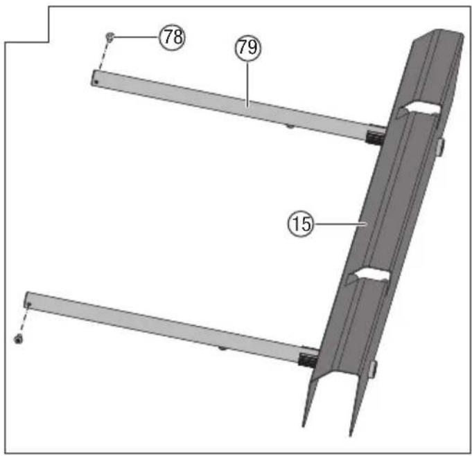
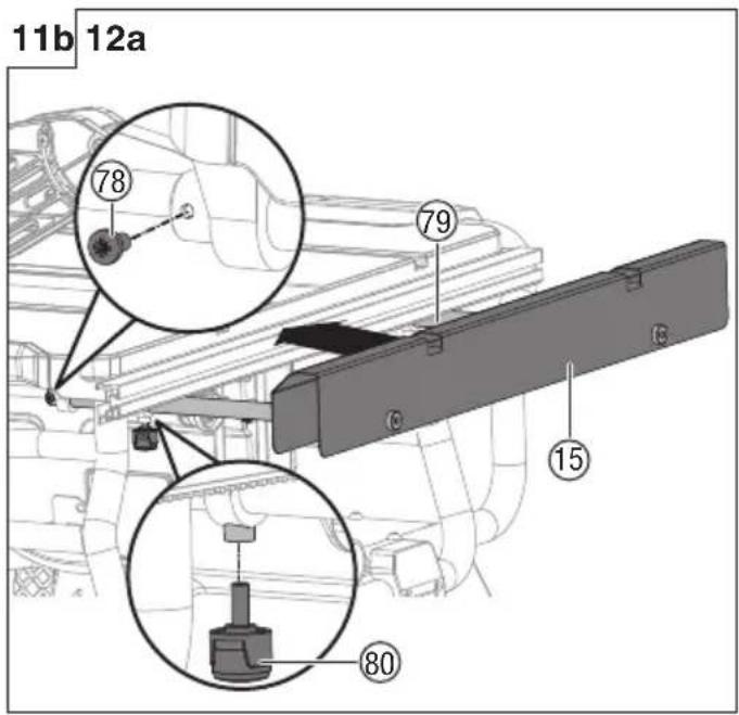
11. Outfeed support assembly installation (F 11a-11b)
- Loosen and remove two stop screws (78) on the extension poles (79) of the outfeed support (15).
- Loosen the locking knobs (80) under the working table counterclockwise.
☐ Insert the rear extension poles (79) into the two holes in the rear of the working table and into the extension tube brackets that are located under the working table. Position the outfeed support (15).
- Thread the locking knobs (80) into the holes under the working table and tighten them.
Thread the two stop screws (78) into the holes located on ends of the extension poles (79) and tighten them.
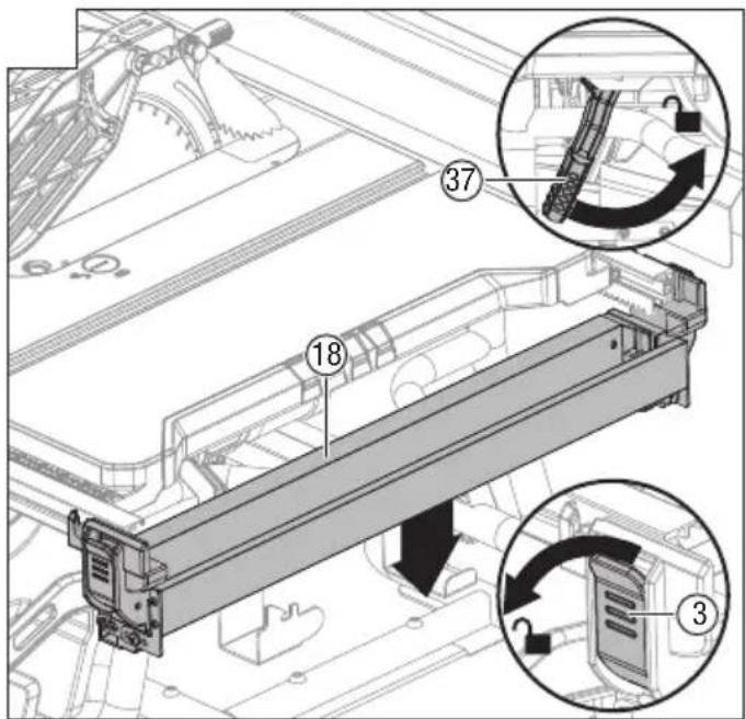
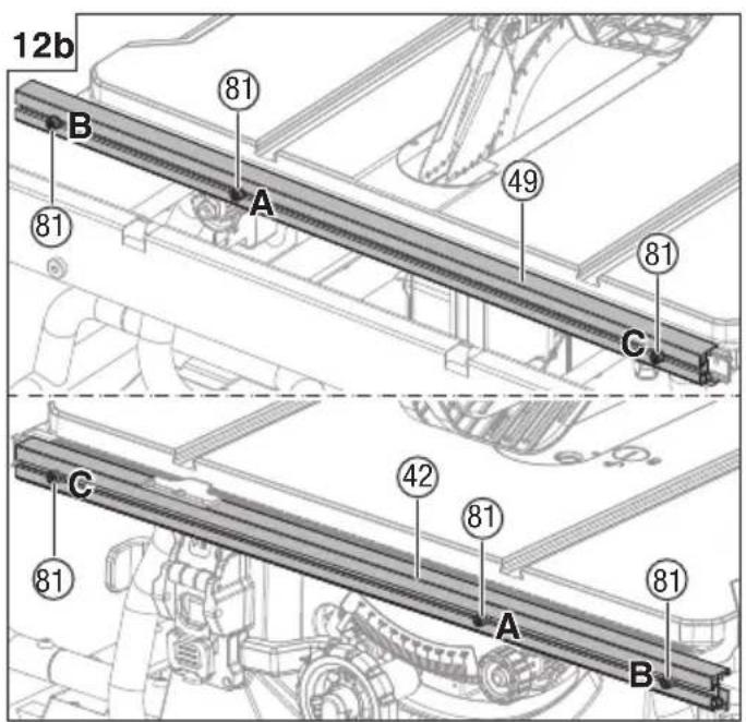
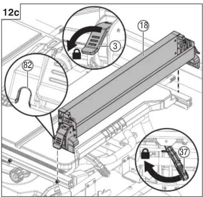
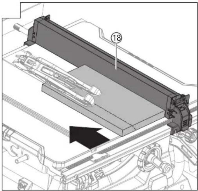
12. Rip fence installation (Fig. 12a-12c)
- Push down the fence rails lock lever (37) toward the
rear of the saw to unlock it.
Open the rip fence lock levers (3) located on two ends of the rip fence (18), then remove the rip fence (18) from the front and rear fence rails (42, 49).
CAUTION
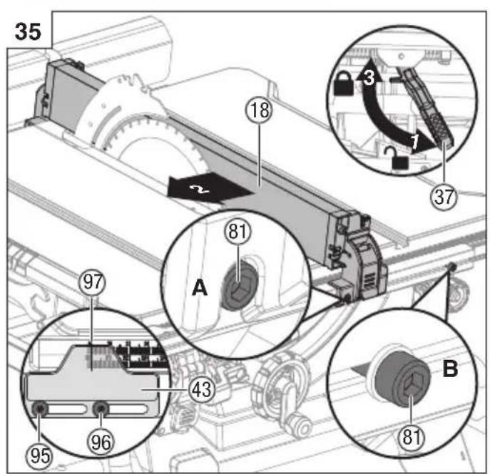
There are three position screws (81) (position A, B, C) on the each front and rear fence rails (42, 49) to attach rip fence. Position screws (81) (position A and B) use for rip fence on the right of saw blade. Position screws (81) (position C) use for rip fence on the left of saw blade. (Fig. 12b)
○ Align the fence slots (82) with the position screws (front and back) on the fence rails.
- Push the slots (82) down onto the position screws and secure the rip fence in place by pushing the rip fence lock levers (3) down.
- Lock the fence rails lock lever (37).
CAUTION
The rip fence should be parallel to the saw blade. If not, refer to the section “Aligning rip fence to blade” (Page 49).
CAUTION
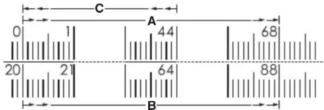
Three position screws (81) (position A, B, C) apply to three different scales: Position screw (Position A): Begin with 0 to 680 mm end. (Rip fence located on the right of the blade)
Position screw (Position B): Begin with 200 mm to 880 mm end. (Rip fence located on the right of the blade)
Position screw (Position C): Begin with 0 to 440 mm end. (Rip fence located on the left of the blade)
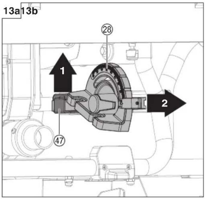
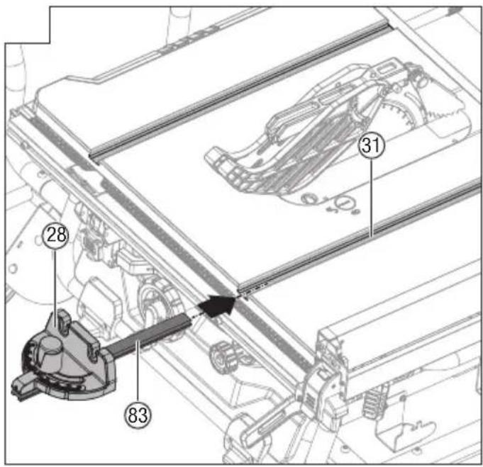
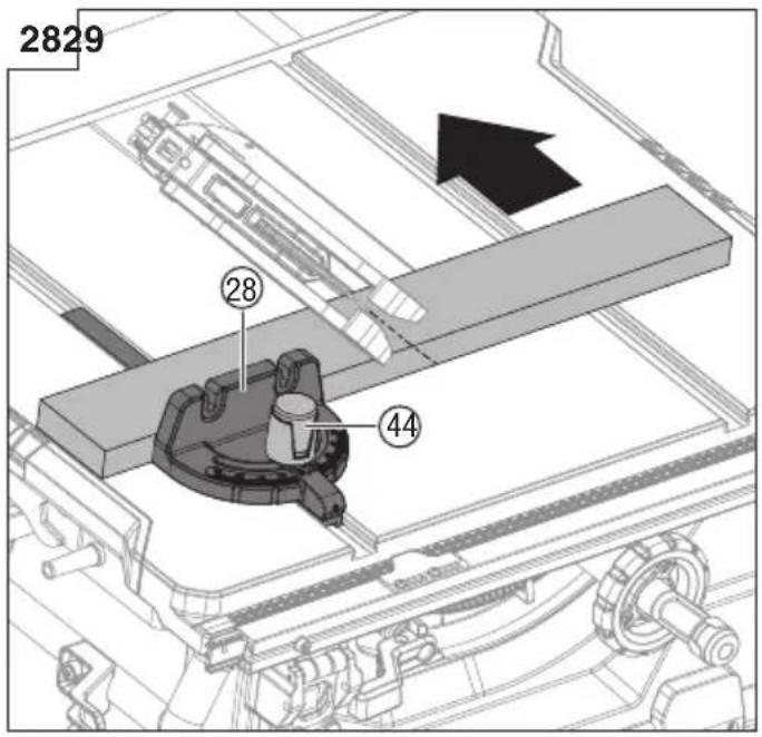
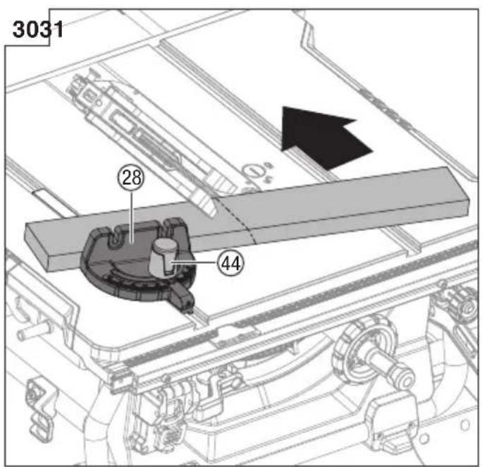
13. Mitre gauge installation (Fig. 13a-13b)
The mitre gauge (28) can be installed on each mitre gauge groove (31) on either side of blade.
- Remove the mitre gauge (28) from mitre gauge storage (47) located on inside of the right side of saw.
- Slide the guide rail (83) of the mitre gauge (28) into one of the guide grooves (31) of the saw table intended for this purpose.
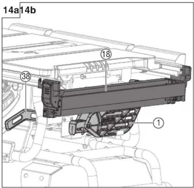
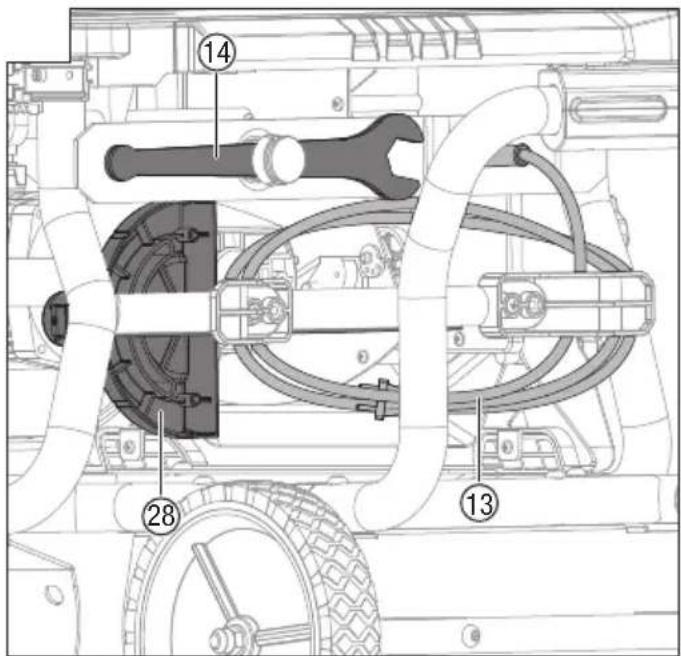
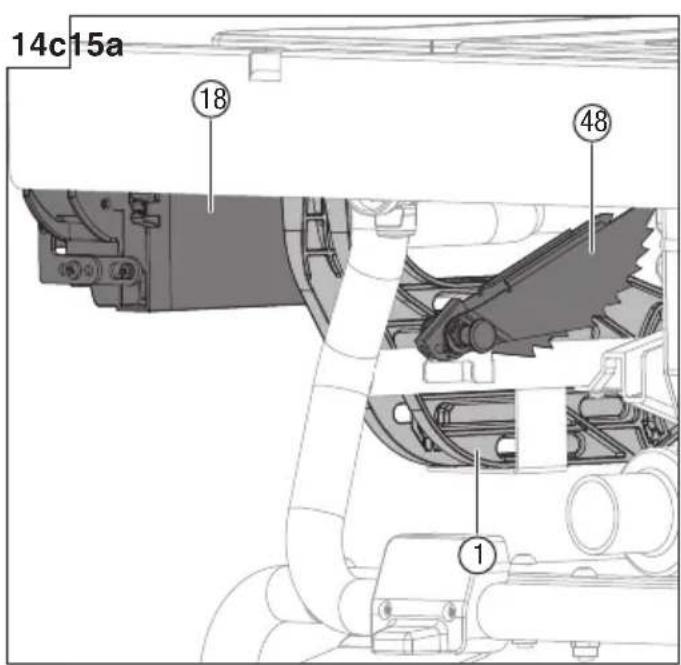
14. To store the table saw accessories (Fig. 14a-14c)
The table saw has two convenient storage areas (one on either side and back of the saw) specifically designed for the saw's accessories: rip fence (18), blade guard (1), push stick (38), blade wrenches (14), power cord (13), anti-kickback pawls (48) and mitre gauge (28).
- When not in use, store accessories securely.
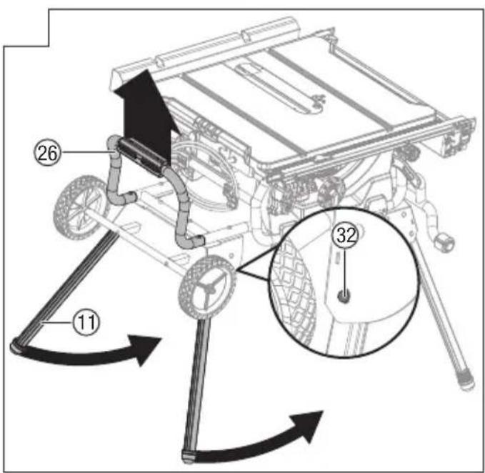
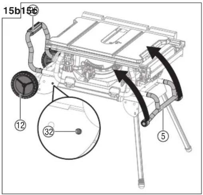
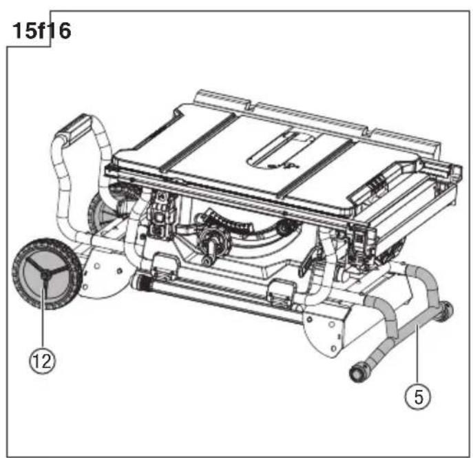
15. Folding the stand (Fig. 15a-15f)
To fold the stand for moving, return fence rails and lock the fence rails lock lever and return outfeed support to inner position. Store the accessories securely.
Grasp the stand support assembly (26) and lift it up until two stand legs (11) (located on side of the wheel) leaving off the ground, then fold in two stand legs (11). To do this, push the lock pins (32) until they unlock the
English
stand legs (11) from the holes, then swing the stand legs (11) upward until the stand legs are locked with the lock pins (32) engage the holes.
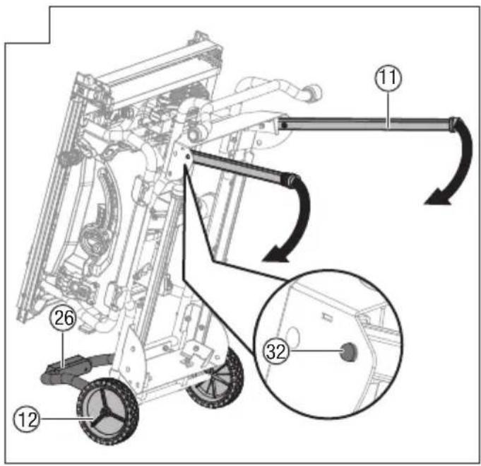
Grasp the handle I (5) and tilt saw back onto wheels until the stand is balanced on the wheels (12) and stand support assembly (26). (Fig. 15b-15c)
☐ Fold in other two stand legs (11). To do this, push the lock pins (32) until they unlock the stand legs (11) from holes, then swing the stand legs downward until the stand legs are locked with the lock pins (32) engage the holes.
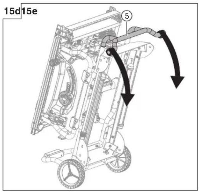
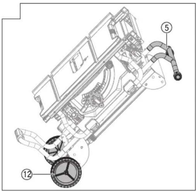
Grasp the handle I (5) firmly and tilt saw to you, push the saw to the desired location (Fig. 15e) then either open the stand or store the saw (Fig. 15d & 15f) in a dry environment.
WARNING
Keep your fingers clear of the hinge points while folding the stand. Danger of fingers being crushed or contused.
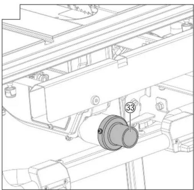
16. Connect to a dust collection system (Fig. 16)
☐ The dust extraction port (33) with (Inner: ∅35 mm, Outer: ∅40 mm) size is located on the back of the table saw.
This port can be connected directly to a dust collection system by connecting the pick up end of the dust collection hose to the dust port.
Particles generated by cutting may contain substances that can cause cancer, allergic reactions, respiratory diseases, birth defects or other reproductive defects. Some examples of such substances are, lead (in paint containing lead), additives used for wood treatment (chromate, wood preservatives), some wood types (such as oak or beech dust).
- The risk depends on how much the user or nearby persons are exposed to these substances.
- Reduce dust exposure with the following measures:
- Do not direct the escaping particles and the exhaust air stream at yourself or nearby persons or dust deposits.
- Ensure ventilation of the workplace and wear appropriate protective equipment, such as respirators designed to filter microscopically small particles
- Collect the generated particles at the source, avoid deposition in the surrounding area.
-
Use the supplied dust collection system and a suitable extraction unit. This ensures that fewer uncontrolled particles are released to the work environment.
-
Use an extraction unit and/or air purifiers.
- Maintain good ventilation of the workplace.
- Keep clean using a vacuum cleaner. Do not sweep or blow. This will stir up dust.
- Vacuum or wash your protective clothing. Do not blow, beat or brush. This will stir up dust.
Observe the relevant guidelines for your material, staff, application and place of application (e.g. occupational health and safety regulations, disposal).
OPERATION
WARNING
To reduce the risk of serious personal injury, turn unit off and unplug the tool before making any adjustments or removing/installing attachments or accessories. An
accidental start-up can cause injury.
WARNING
Before using the saw, verify the following each and every time:
- ALWAYS wear proper eye, hearing and respiratory equipment.
- Blade is securely tightened.
- Bevel angle and fence rails lock lever is locked.
- If ripping, ensure that rip fence lock lever is locked and that the fence is parallel to the blade.
- If crosscutting, mitre gauge lock knob is securely tightened.
- The blade guard assembly is properly attached and the anti-kickback pawls assembly is functioning.
WARNING
To reduce the risk of serious personal injury, if the distance between the rip fence and saw blade is less than 150 mm, the push stick must be used.
WARNING
Feed the workpiece into the saw blade only against the direction of rotation. Feeding the workpiece in the same direction that the saw blade is rotating above the working table may result in the workpiece, and your hand, being pulled into the saw blade.
WARNING
In the event of a power failure or when the tool is not in use, turn the switch OFF. This action will prevent the tool from accidentally starting when power returns.
WARNING
ALWAYS make sure your workpiece is not in contact with the blade before operating the switch to start the saw. Blade contact could result in kickback or thrown workpiece.
WARNING
To reduce the risk of accidental starting, ALWAYS make sure the switch is in the OFF position before plugging saw into the power source.
WARNING
DO NOT use blades rated less than the speed of this tool. Failure to heed this warning could result in serious personal injury.
WARNING
The operation of any power tool can result in foreign objects being thrown into the eyes, which can result in severe eye damage. Always wear eye protection before commencing power tool operation.
WARNING
Never operate the saw with the blade guard removed except for non-through cuts, failure to heed this instruction could result in serious personal injury.
1. Applications
You can use this tool for the purposes listed below:
- Straight-line cutting operations, such as cross cut, rip cut, mitre cut, and compound cut.
- Cabinet making and woodworking.
NOTE
This table saw is designed to cut wood and wood composition products only. Never cut metals, cement board, or masonry.
2 Operating components
The upper portion of the blade projects up through the table and is surrounded by an insert called the table insert. The height of the blade is set with a height
adjusting handle on the height/bevel adjusting handwheel. Detailed instructions are provided in this manual for the basic cut: cross cuts, mitre cuts, bevel cuts, and compound cuts.
The rip fence is used to position workpiece for lengthwise cuts and used for outfeed support for large workpiece cuts.
It's very important to use the riving knife, anti-kickback pawls and blade guard assembly for all through cut sawing operations.
3. Causes of kickback
Kickback can occur when the blade stalls or binds, causing the workpiece to be kicked back toward the operator with great force and speed. If your hands are near the saw blade, they may be jerked loose from the workpiece and come into contact with the blade. Obviously, kickback can cause serious injury, and it is well worth using precautions to avoid the risks. Kickback can be caused by any action that pinches the blade in the wood, such as the following:
○ Making a cut with incorrect blade depth.
- Sawing into knots or nails in the work piece.
- Twisting the wood while making a cut.
- Failing to support the workpiece.
- Forcing a cut.
- Cutting warped or wet lumber.
○ Using the wrong blade for the type of cut.
- Not following correct operating procedures.
- Misusing the saw.
- Failing to use the anti-kickback pawls.
- Cutting with a dull, gummed-up, or improperly set blade.
4. Precautions of kickback NOTE
Kickback can be avoided by taking following proper precautions:
- Never stand directly in line with the saw blade. Always position your body on the same side of the saw blade as the fence.
Kickback may propel the workpiece at high velocity towards anyone standing in front and in line with the saw blade.
- Never reach over or in back of the saw blade to pull or to support the workpiece.
Accidental contact with the saw blade may occur or kickback may drag your fingers into the saw blade.
- Never hold and press the workpiece that is being cut off against the rotating saw blade.
Pressing the workpiece being cut off against the saw blade will create a binding condition and kickback.
- Align the fence to be parallel with the saw blade.
A misaligned fence will pinch the workpiece against the saw blade and create kickback.
- Use extra caution when making a cut into blind areas of assembled workpieces.
The protruding saw blade may cut objects that can cause kickback.
- Support large panels to minimise the risk of saw blade pinching and kickback.
Large panels tend to sag under their own weight. Support(s) must be placed under all portions of the panel overhanging the table top.
- Use extra caution when cutting a workpiece that is
twisted, knotted, warped or does not have a straight edge to guide it with a mitre gauge or along the fence.
A warped, knotted, or twisted workpiece is unstable and causes misalignment of the kerf with the saw blade, binding and kickback.
- Never cut more than one workpiece, stacked vertically or horizontally.
The saw blade could pick up one or more pieces and cause kickback.
- When restarting the saw with the saw blade in the workpiece, center the saw blade in the kerf so that the saw teeth are not engaged in the material.
If the saw blade binds, it may lift up the workpiece and cause kickback when the saw is restarted.
- Keep saw blades clean, sharp, and with sufficient set. Never use warped saw blades or saw blades with cracked or broken teeth.
Sharp and properly set saw blades minimise binding, stalling and kickback.
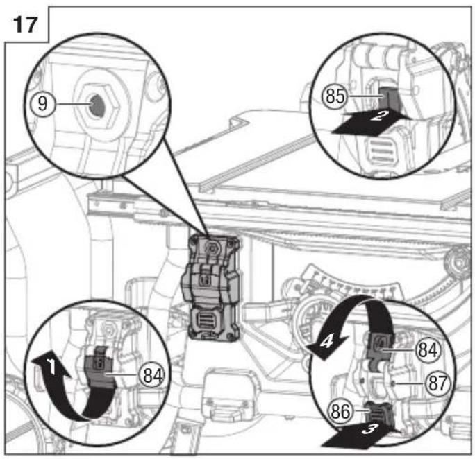
5. Switch assembly (Fig. 17) WARNING
To reduce the risk of injury, be sure switch is in the OFF position before plugging machine in.
To turn saw on and off:
- Flip the switch cover (84) upward.
- Press the switch I (85) to turn on the saw.
- Press the switch paddle (86) to turn off the saw.
To lock saw:
- Flip the switch cover (84) downward.
The holes (87) is provided in the switch for insertion of a padlock with a removable shank to lock the saw off.
NOTE
A conventional padlock will not fit.
6. Overload protection (Fig. 17)
The saw is equipped with an overload switch (9) to prevent the saw from overload damage. The saw will automatically shut off if the machine was with overloaded cutting or low voltage. Wait for the motor to cool down at least five minutes.
And press the overload reset switch button to resume the overload switch. After the motor has cooled down, press the green "I"-button on the ON/OFF switch to restart saw.
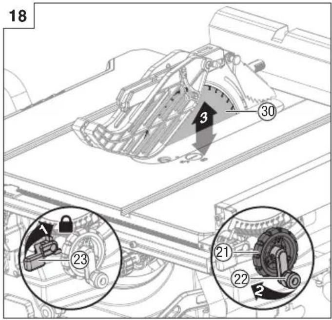
7. Changing blade depth (Fig. 18)
Blade depth should be set so that outer points of blade are higher than workpiece by approximately 3 mm to 6 mm and bottom of gullets are below top surface of workpiece.
Turn the bevel lock lever (23) clockwise to tighten it securely.
- Raise blade (30) by turning height adjusting knob (22) on the height/bevel adjusting handwheel (21) clockwise. Lower blade by turning height adjusting knob (22) counter-clockwise.
- Make sure blade (30) is at proper height.
WARNING
Make sure the blade guard is in place after adjusting the blade depth. Failure to heed this instruction could result in serious personal injury.
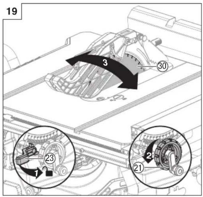
8. Changing blade angle (bevel) (Fig. 19) CAUTION
A 90^ cut has a 0^ bevel and a 45^ cut has a 45^ bevel.
CAUTION
English
If bevel indicator is not at zero when saw blade is at 0^ , see the section "Adjusting bevel indicator" (Page 50).
- Loosen the bevel lock lever (23) counter-clockwise.
- Adjust bevel angle by first pushing height/bevel adjusting handwheel (21) all the way to the left.
○ Holding height/bevel adjusting handwheel, slide bevel indicator to the right to increase angle of blade (30) (bringing it closer to 45° from the tabletop). Holding height/bevel adjusting handwheel, slide bevel indicator to the left to decreases the angle (bringing blade closer to 90° from the table top).
○ Make sure blade (30) is at desired angle. Tighten bevel lock lever (23) clockwise.
WARNING
Make sure the blade guard is in place after adjusting blade angle. Failure to heed this instruction could result in serious personal injury.
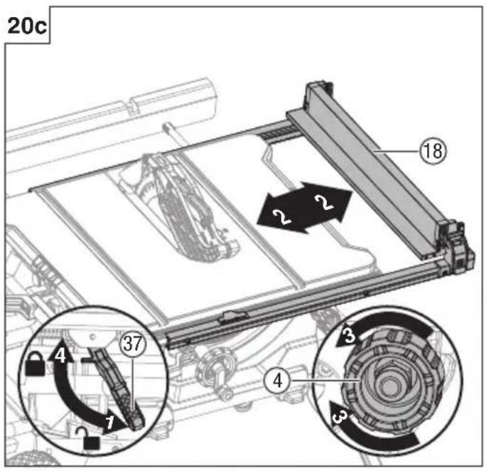
9. Rip fence (Fig. 20a-20c)
WARNING
To reduce the risk of injury, always make sure the rip fence is parallel to the blade before beginning any operation.
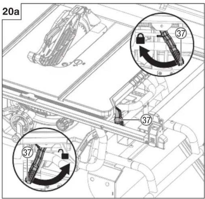
Fence rails lock lever (Fig. 20a)
The fence rails lock lever locks the rip fence in place preventing movement during cutting.
To lock the fence rails lock lever (37), push it up and toward the front of the saw.
To unlock the fence rails lock lever (37), push it down and toward the rear of the saw.
CAUTION
When ripping, always lock the fence rails lock lever.
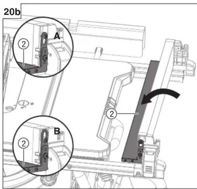
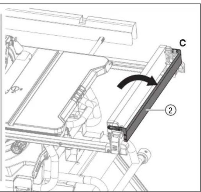
Narrow fence (Fig. 20b)
When using the narrow fence (2) to support a workpiece that extends beyond the working table, rotate the narrow fence (2) as shown in (Fig. 20b) and secure it inthe lowest position A for both the front and back slots.
When using the narrow fence (2) to cut a narrow workpiece, rotate the narrow fence (2) as shown in (Fig. 20b) and secure it in the upper position B for both the front and back slots.
CAUTION
Always use the auxiliary fence (not the narrow fence) when ripping material 3 mm or thinner to prevent stock from slipping under the fence.
NOTE
If the narrow fence is not required, always place it in the position C as shown (Fig. 20b).
NOTE
The narrow fence (2) for cutting a narrow workpiece can provide more space for a push stick without removing the blade guard.
Adjusting knob (Fig. 20c)
The adjusting knob allows smaller adjustments when setting the rip fence.
- Unlock the fence rails lock lever (37).
- Slide the rip fence (18) close to the desired position.
☐ Slowly turn the adjusting knob (4) to set the rip fence (18) to desired position. Turn the adjusting knob (4) clockwise will extend the fence rails to right. Turn the adjusting knob (4) counter-clockwise will extend the fence rails to left.
- Lock the fence rails lock lever (37).
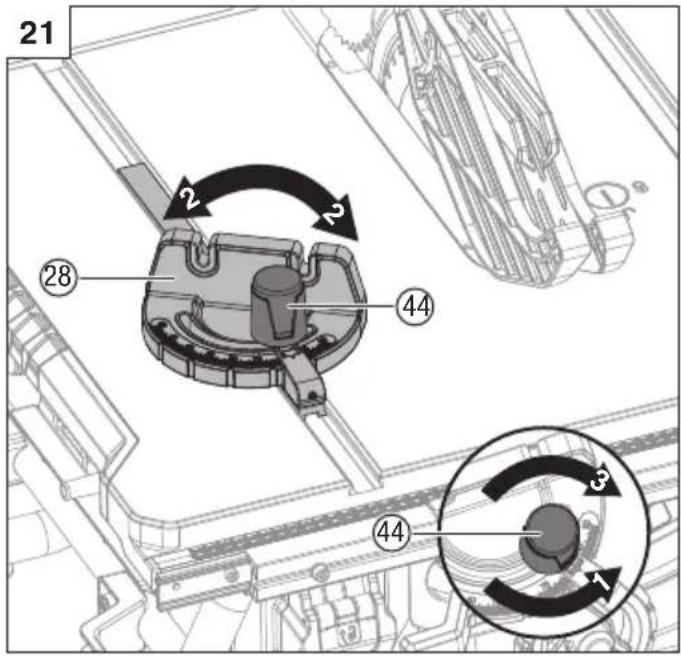
10. Mitre gauge (Fig. 21)
The mitre gauge (28) provides accuracy in angled cuts. For very close tolerances, test cut are recommended. There are two mitre gauge grooves, one on either side of blade. When making a 90^ cross cut, use either mitre gauge groove. When making a beveled cross cut (blade tilted in relation to working table, mitre gauge should be located in groove on right so that blade is tilted away from mitre gauge and hands.
Using mitre gauge
- Loosen mitre gauge lock knob (44) turning it counterclockwise.
With mitre gauge in mitre gauge groove, rotate gauge until desired angle on scale is reached.
- Retighten mitre gauge lock knob (44) turning it clockwise.
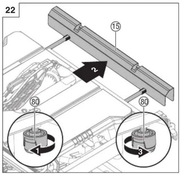
11. Outfeed support (Fig. 22)
The outfeed support slides to give operator additional support for cutting long workpieces.
- Unplug the saw.
- Loosen the lock knobs (80) under the working table counter-clockwise.
- Stand behind saw. Grasp outfeed support (15) with both hands and pull until it is fully extended.
- Tighten the lock knobs (80) clockwise.
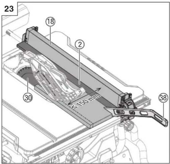
12. Push stick (Fig. 23)
Push stick (38) is a device used for safely pushing a work piece through the blade instead of using your hands. A push stick is included with your saw, but it can be made from scrap wood in various sizes and shapes to be used in a specific project. The stick must be narrower than the work piece, with a 90° notch in one end and shaped for a grip on the other end.
Push stick should be used in place of the user's hand to guide the material between the fence and blade. When using a push stick, the trailing end of the board must be square.
A push stick against an uneven end could slip off or push the work piece away from the fence, which may cause kickback resulting in serious personal injury.
The push stick can be stored in the push stick storage (36).
WARNING
Always use the push stick with the narrow fence (2) whenever the fence is 150 mm or less from the blade.
WARNING
When the push stick is not in use, always it must be stored in the push stick storage.
13.Throughcuts
WARNING
Always make sure the blade guard and anti-kickback pawls are in place and working properly when making these cuts to avoid possible injury.
WARNING
Use extra caution when cutting wood products having slippery surface as the anti-kickback pawls may not always be effective.
WARNING
DO NOT use blades rated less than the speed of this tool. Failure to heed this warning could result in personal injury.
WARNING
To avoid kickback, make sure one side of the workpiece
is securely against the rip fence during any rip cut, and hold the workpiece firmly against the mitre gauge during any mitre cut.
WARNING
DO NOT attempt compound mitre cuts, with blade beveled and mitre fence angled, until you are thoroughly familiar with the basic cuts and understand how to avoid kickback.
WARNING
DO NOT attempt to make any cuts not covered here.
WARNING
Using rip fence as a cutoff gauge when cross cutting will result in kickback which can cause serious personal injury.
WARNING
NEVER make freehand cuts (cuts without mitre gauge or rip fence). Unguided workpieces can result in serious injury.
WARNING
Never make through cuts without the blade guard in place. Failure to heed this instruction could result in serious personal injury.
14. Cutting tips
The kerf (the cut made by the blade in the wood) will be wider than the blade to avoid overheating or binding. Make allowance for the kerf when measuring wood.
- Make sure the kerf is made on the waste side of the measuring line.
- Cut the wood with the finish side up.
- Knock out loose knots before making cut.
- Always provide proper support for wood as it comes out of saw.
15. Making cuts
- Stand slightly to the side of blade path to reduce the chance of injury should kickback occur.
Use mitre gauge when making cross, mitre, bevel and compound mitre cuts. To secure angle, lock mitre gauge in place by twisting lock knob clockwise. ALWAYS tighten lock knob securely in place before use.
WARNING
Never use the fence and mitre gauge together. This may cause a kickback condition and injury to the operator.
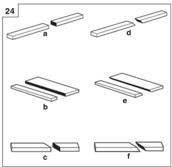
16. Types of cuts (Fig. 24)
There are six basic cuts: a) the cross cut, b) the rip cut, c) the mitre cut, d) the bevel cross cut, e) the bevel rip cut, and f) the compound (bevel) mitre cut.
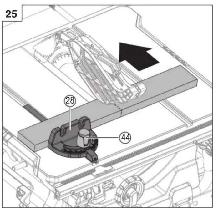
17. Making a cross cut (Fig. 25)
- Remove rip fence.
- Set blade to correct depth for workpiece.
- Set mitre gauge (28) to 0° and tighten lock knob (44).
○ Make sure wood is clear of blade before turning on saw.
- To turn saw on, press switch button.
- Let blade build up to full speed before moving workpiece into blade.
- Hand closest to blade should be placed on mitre gauge lock knob and hand farthest from blade should be placed on workpiece. Feed workpiece into blade.
When cut is complete, turn saw off. Wait for blade to come to a complete stop before removing workpiece.
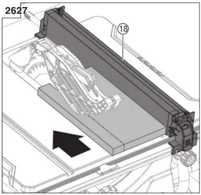
18. Making a rip cut (Fig. 26)
- Set blade to correct depth for workpiece.
- Unlock the fence rail lock lever and slide rip fence (18) to desired distance from blade for cut.
- Lock the fence rail lock lever.
- Make sure wood is clear of blade before turning on saw.
- When ripping a long workpiece, slide the outfeed support to fully extend.
- To turn saw on, press switch button.
- Position workpiece flat on table with edge flush against rip fence (18). Let blade build up to full speed before feeding workpiece into blade.
Once blade has made contact with workpiece, use hand closest to rip fence for guidance. Make sure edge of workpiece remains in solid contact with both rip fence and surface of table. If ripping a narrow piece, use push stick and/or push blocks to move piece through cut and past blade.
- When cut is complete, turn saw off. Wait for blade to come to a complete stop before removing workpiece.
WARNING
When ripping, always apply the workpiece feeding force between the fence and the saw blade. Use a push stick when the distance between the fence and the saw blade is less than 150 mm, and use a push block when this distance is less than 50 mm. Cutting aids will keep your hand at a safe distance from the saw blade.
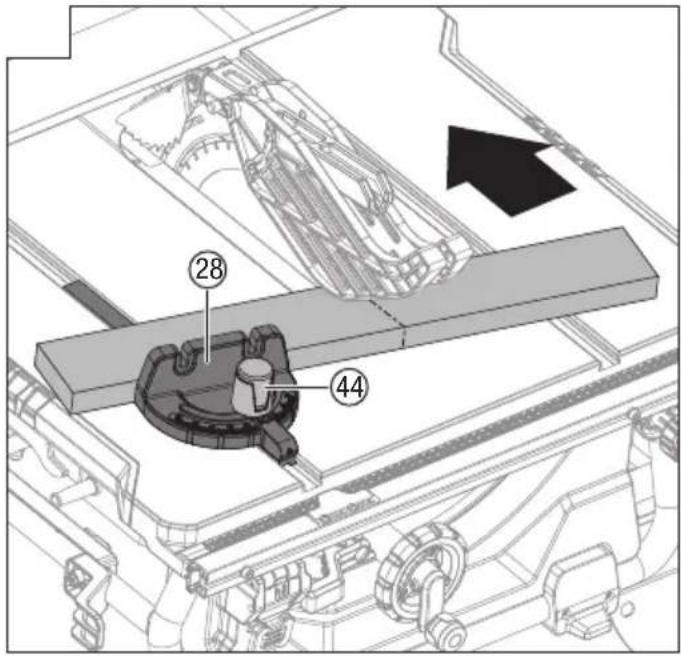
19. Making a mitre cut (Fig. 27)
- Remove rip fence.
- Set blade to correct depth for workpiece.
- Set mitre gauge (28) to the desired angle and tighten lock knob (44).
- Make sure the wood is clear of the blade before turning on the saw.
Turn the saw on.
- Let the blade build up to full speed before moving the workpiece into the blade.
- Hand closest to blade should be placed on mitre gauge lock knob and hand farthest from blade should be placed on workpiece. Feed workpiece into blade.
- When cut is complete, turn saw off. Wait for blade to come to a complete stop before removing workpiece.
20. Making a bevel cross cut (Fig. 28)
- Remove rip fence.
- Unlock bevel lock lever.
- Adjust bevel angle to desired setting.
- Lock bevel lock lever.
- Set blade to correct depth for workpiece.
- Set mitre gauge (28) to 0° and tighten lock knob (44).
○ Make sure wood is clear of blade before turning on saw.
- Turn saw on.
- Let blade build up to full speed before moving workpiece into blade.
- Hand closest to blade should be placed on mitre gauge lock knob and hand farthest from blade should be placed on workpiece. Feed workpiece into blade.
When cut is complete, turn saw off. Wait for blade to come to a complete stop before removing workpiece.
21. Making a bevel rip cut (Fig. 29)
WARNING
Make sure that the rip fence is on the right side of the blade to avoid trapping the wood and causing kickback.
English
Kickback and serious personal injury will result if the rip fence is placed to the left of the blade.
- Remove mitre gauge.
- Unlock bevel lock lever.
- Adjust bevel angle to desired setting.
- Lock bevel lock lever.
- Set blade to correct depth for workpiece.
- Unlock the fence rails lock lever and slide rip fence (18) to desired distance from blade for cut.
- Lock the fence rails lock lever.
- Make sure wood is clear of blade before turning on saw.
- When ripping a long workpiece, slide the outfeed support to fully extend.
Turn saw on.
- Position workpiece flat on table with edge push against rip fence (18).
- Let blade build up to full speed before moving workpiece into blade.
Once blade has made contact with workpiece, use hand closest to rip fence for guidance. Make sure edge of workpiece remains in solid contact with both rip fence and surface of table. If ripping a narrow piece, use push stick to move piece through cut and past blade.
- When cut is complete, turn saw off. Wait for blade to come to a complete stop before removing workpiece.
22. Making a compound (bevel) mitre cut (Fig. 30)
- Remove rip fence.
- Unlock bevel lock lever.
- Adjust bevel angle to desired setting.
- Lock bevel lock lever.
- Set blade to correct depth for workpiece.
- Set mitre gauge (28) to desired angle and tighten lock knob (44).
○ Make sure wood is clear of blade before turning on saw.
- Turn the saw on.
- Let the blade build up to full speed before moving the workpiece into the blade.
- Hand closest to blade should be placed on mitre gauge lock knob and hand farthest from blade should be placed on workpiece. Feed workpiece into blade.
When cut is complete, turn saw off. Wait for blade to come to a complete stop before removing workpiece.
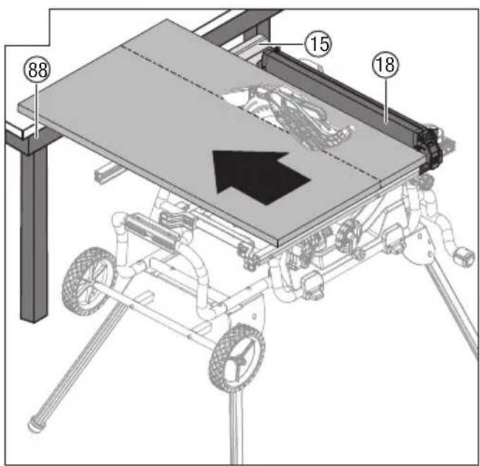
23. Making a large panel cut (Fig. 31)
- Slide the outfeed support (15) to fully extend, and place a support (88) the same height as top of working table behind saw for cut and add supports to sides as needed.
○ Depending on shape of panel, use rip fence or mitre gauge. If panel is too large to use either rip fence or mitre gauge, it is too large for this saw.
- Make sure wood does not touch blade before saw is turned on.
- Turn the saw on.
- Position workpiece flat on table with edge flush against rip fence. Let blade build up to full speed before feeding workpiece into blade.
- Use push stick to move piece through cut and past blade.
- When cut is complete, turn saw off. Wait for blade to
come to a complete stop before removing workpiece.
24. Making a non-through cut
The use of a non-through cut is essential to cutting grooves and rabbets. Non-through cuts can be made using a standard blade having a diameter of 254 mm. Non-through cuts are the only type of cuts that should be made without the blade guard assembly and anti-kick-back pawls installed. Make sure the blade guard assembly and anti-kickback pawls are reinstalled upon completion of this type of cut.
WARNING
To reduce the risk of serious injury when making non through cuts, follow all applicable warnings and instructions listed below in addition to those listed above for the relevant through cut.
WARNING
When making a non-through cut, blade is covered by workpiece during most of cut. Be alert to exposed blade at start and finish of every cut to avoid the risk of personal injury.
WARNING
Never feed wood with hands when making any non-through cuts such as rabbets. To avoid personal injury, always use push blocks, push sticks, and/or featherboards.
WARNING
Read the appropriate section which describes the type of cut in addition to this section on non-through cuts. For example, if your non-through cut is a straight cross cut, read and understand the section on straight cross cuts before proceeding.
WARNING
Once non-through cuts are completed, unplug saw and reinstall riving knife in uppermost position. Install anti-kickback pawls and blade guard.
- Unplug saw.
- Unlock release lever.
- Adjust bevel angle to 0°.
- Lock release lever.
- Remove blade guard (1) and anti-kickback pawls (48).
- Set the riving knife (16) in "MIDDLE" position and lock the riving knife lock knob (61).
- Plug saw into power source and turn saw on.
- Let blade build up to full speed before moving workpiece into blade.
Always use push blocks, push sticks, and/or feather-board when making non-through cuts to reduce the risk of serious injury.
- When cut is made, turn saw off. Wait for blade to come to a complete stop before removing workpiece.
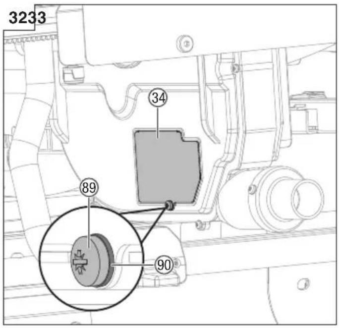
25. Dust collection (Fig. 32)
This table saw is equipped with a dustshroud and dust collection port. For best results, connect a vacuum to the port at the rear of the saw. After extended use, the saw's dust collection system may become clogged.
To clear the dust collection system:
- Unplug the saw.
- Loosen and remove the screw (89) and flat washer (90), then open the small baffle (34).
- Clean out the excess dust, and push the small baffle in place, replace the flat washer and screw.
ADJUSTMENTS
WARNING
Before performing any adjustment, make sure tool is unplugged from power supply and switch is in off position. Failure to do so could result in serious personal injury.
WARNING
Make sure the blade guard is reinstalled immediately after making any adjustment which requires it to be removed. Failure to heed this instruction could result in serious personal injury.
The table saw has been adjusted at the factory for making very accurate cuts. However, some components might have been jarred out of alignment during shipping. Also, over a period of time, readjustment will probably become necessary due to wear.
Carefully check alignment with a framing square before beginning adjustments to confirm whether they are necessary. Use test cuts after completing adjustments to avoid damaging workpiece.
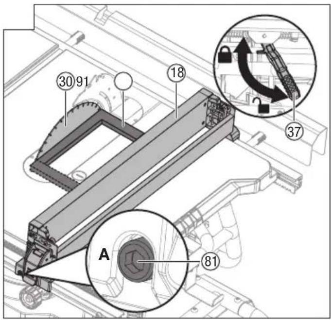
1. Aligning rip fence to blade (Fig. 33)
Rip fence and blade alignment is set at factory and in most cases will not need to be adjusted. However, the alignment should always be checked after installing blade or before making cuts, and can be adjusted if necessary. If rip fence is out of alignment with blade, adjustment is needed.
WARNING
Rip fence must be aligned to blade so that wood does not bind, resulting in kickback. Failure to do so could result in serious personal injury.
DO NOT loosen any position screws for this adjustment until alignment has been checked with a square to be sure adjustment are necessary. Once screws are loosened, items must be reset.
WARNING
Unplug saw. Remove blade guard and anti-kickback pawls. Raise the blade by turning height adjusting knob.
To check/adjust
- Place the framing square (91) beside the blade (30), and unlock the fence rails lock lever (37) to move the rip fence (18) up to the square.
- Lock the fence rails lock lever (37) and note the measurement on the rip scale.
- Move the fence back and rotate the framing square (91) 180° to check the other side.
○ If the two measurements are not the same, loosen the position screws (81) on the extension poles and then align it.
- Retighten the position screws with 5 mm hex key (supplied). Recheck alignment after position screws are retightened.
- Reinstall the blade guard and anti-kickback pawls.
○ Make two or three test cuts using scrap wood. If the cuts are not true, repeat the process.
WARNING
The adjustment must be correct. If it is not, kickback could result in a serious injury and inability to make accurate cuts.
WARNING
Make sure the blade guard is reinstalled immediately after making any adjustment which requires it to be removed.
Failure to heed this instruction could result in serious personal injury.
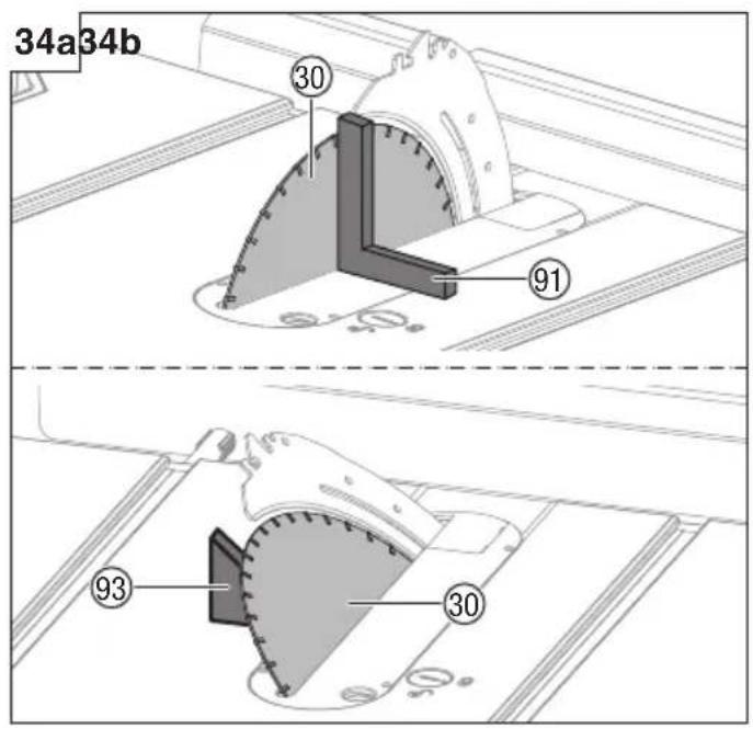
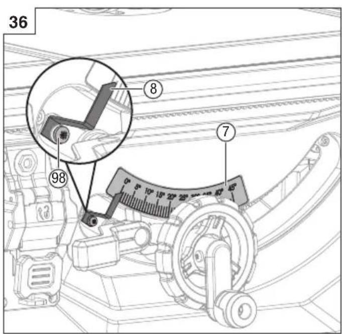
2. Bevel adjustment (Fig. 34a-34b)
This saw has positive stops that will quickly position the saw blade at 90^ ( 0^ ) or 45^ to the table. Angle settings of saw have been set at the factory and, unless damaged in shipping, should not require setting during assembly. After extensive use, they may need to be checked.
To check 90° (0°) bevel
- Unplug the saw.
- Raise the blade to the maximum height by turning the height adjusting knob clockwise.
- Remove the anti-kickback pawls and blade guard.
○ Using a framing square (91), set the blade (30) to exactly 90^ .
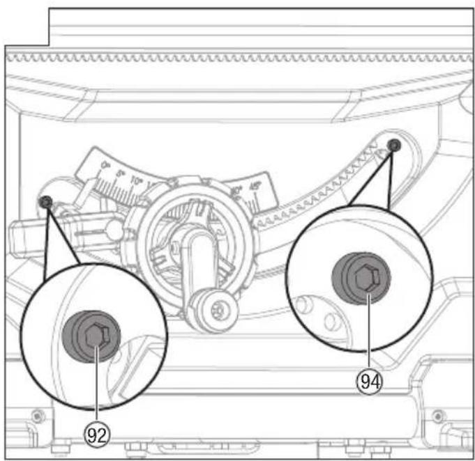
☐ If the blade stops bevelling before it gets to 90^ , loosen the 90^ stop set screw (92) (located at the left of the bevel track on the front), and then adjust it to 90^ .
With the blade set at 90°, slowly turn the 90° stop set screw (92) until you feel resistance. Bevel the blade away from 90° a little, and then back to the stop.
- Re-measure the angle and repeat the stop adjustment as necessary until the blade stops at 90°.
To check 45° bevel
- Unplug the saw.
- Raise the blade to the maximum height by turning the height adjusting knob clockwise.
- Remove the anti-kickback pawls and blade guard.
○ Using a triangle square (93), set the blade (30) to exactly 45^ .
☐ If the blade stops bevelling before it gets to 45^ , loosen the 45^ stop set screw (93) (located at the right of the bevel track on the front), and then adjust it to 45^ .
With the blade set at 45^ , slowly turn the 45^ stop set screw (93) until you feel resistance. Bevel the blade away from 45^ a little, and then back to the stop.
- Re-measure the angle and repeat the stop adjustment as necessary until the blade stops at 45°.
CAUTION
For easy of use, bevel adjust should stop at 45^ and 90^ .
WARNING
Make sure the blade guard and anti-kickback pawls are reinstalled immediately after making any adjustment which requires it to be removed. Failure to heed this instruction could result in serious personal injury.
3. Adjusting rip fence scale indicator (Fig. 35)
- Remove the anti-kickback pawls and blade guard.
- Unlock the fence rails lock lever (37).
Mount the rip fence in position A. Adjust the blade to bevel 0° and then allow the left side of the rip fence (18) to touch the blade.
- Lock the lock lever (37) of the fence rails.
○ Loosen the screws (95, 96) of the rip fence scale indicator (43) and set the red pointer (97) on the rip fence scale indicator (43) to be aligned with the zero point.
- Retighten the screws (95, 96) of the rip fence scale indicator (43).
NOTE
When the rip fence (18) is mounted on the right side of the blade, there are two positions. In position A, please read the top rip scale; It will be from 0 to 680 mm.
English
In position B, please read the bottom scale; It will be from 200 mm to 880 mm.
4. Adjusting bevel indicator (FIG. 36)
Adjust the red line on the bevel indicator if it is not aligned with zero when the blade is perpendicular to the table.
With blade perpendicular to table, loosen screw (98).
- Set the bevel indicator (8) to align with 0^ on bevel scale (7).
- Retighten screw (98).
MAINTENANCE
WARNING
When servicing, use only identical replacement parts. Use of any other part may create a hazard or cause product damage.
WARNING
Always wear eye protection during power tool operation or when blowing dust. If operation is dusty, also wear a dust mask.
WARNING
Before performing any maintenance, make sure the tool is unplugged from the power supply and switch is in the off position.
WARNING
DO NOT at any time let brake fluids, gasoline, petroleum-based products, penetrating oils, etc., come in contact with plastics parts. Chemicals can damage, weaken, or destroy plastic.
WARNING
Make sure the blade guard is reinstalled immediately after finishing any maintenance which requires it to be removed. Failure to heed this instruction could result in serious personal injury.
1. General maintenance
- Avoid using solvents when cleaning plastic parts. Most
plastics are susceptible to damage from various types of commercial solvents and may be damaged by their use. Use clean cloths to remove dirt, dust, oil, grease, etc.
Periodically check all clamps, nuts, bolts, and screws for tightness and condition. Make sure the table insert is in good condition and level with the working table.
- Check the blade guard assembly after performing maintenance to make sure it is installed correctly and functioning properly.
- Clean plastic part only with a soft damp cloth. DO NOT use any aerosol or petroleum solvents.
2. Lubrication
All of the bearings in this tool are lubricated with a sufficient amount of high grade lubricant for the life of the unit under normal operating conditions. Therefore, no further lubrication is required.
3. Service and repairs
All quality power tools will eventually require servicing or replacement of parts because of wear from normal use. To assure that only authorized replacement parts will be used and that the double insulation system will be protected, all service (other than routine maintenance) must be performed by an HiKOKI Authorized Service Center ONLY.
NOTE
Specifications are subject to change without any obligation on the part of HiKOKI.
4. Storage
After operation of the tool has been completed, check that the following has been performed:
- Switch is in OFF position.
- Power plug has been removed from the receptacle.
When the tool is not use, keep it stored in a dry place out of the reach of children.
TROUBLESHOOTING
WARNING
To avoid injury from an accidental start, turn the switch OFF and always remove the plug from the power source before making any adjustments.
All electrical or mechanical repairs should be done only by qualified service technicians. Contact HiKOKI Authorized Service Center.
Consult HiKOKI Authorized Service Center if for any reason the motor will not run.
| PROBLEM PROBLEM CAUSE | | CORRECTIVE ACTION |
| Saw will not start. | Overload tripped.Saw is not plugged in.Fuse blown or circuit breaker tripped.Cord is damaged. | Allow motor to cool and reset by pushing overload reset switch.Plug in saw.Replace fuse or reset circuit breaker.Have the cord replaced by an Authorized Service Center. |
| Does not make 45° and 90° rip cuts. | Positive stop not adjusted correctly.Bevel angle pointer not set accurately.Rip fence not properly aligned. | See section “Bevel adjustment”.See section “Adjusting bevel indicator”.See section “Aligning rip fence to blade”. |
| Material pinches blade when ripping. | Rip fence not aligned with blade.Warped wood, edge against fence is not straight. | See section “Aligning rip fence to blade”.Select another piece of wood. |
| Material binds on riving knife. | Riving knife not aligned correctly with blade. | Align riving knife with blade.CORRECTIVE ACTIONPROBLEM PROBL |
| Saw makes unsatisfactory cuts. | ○ Dull blade.○ Blade mounted backwards.○ Gum or pitch on blade.○ Incorrect blade for work being done.○ Gum or pitch on blade causing erratic feed. | ○ Replace with the specified blade.○ Turn the blade around.○ Remove the blade and clean with turpentine and coarse steel wool.○ Change the blade.○ Clean table with turpentine and steel wool. |
| Material kicked back from blade. | ○ Riving knife not aligned correctly with blade.○ Feeding stock without rip fence.○ Riving knife not in place.○ Dull blade.○ The operator letting go of material before it is past saw blade.○ Mitre gauge lock knob is not tightened. | ○ Align riving knife with blade.○ Install and use rip fence.○ Install and use riving knife (with guard).○ Replace with the specified blade.○ Push material all the way past saw blade before releasing work.○ Tighten lock knob. |
| Blade does not raise or bevel freely. | ○ Sawdust and dirt in elevation/beveling mechanisms. | ○ Brush or blow out loose dust and dirt. |
| Blade does not come up to speed or reset trips too easily. | ○ Extension cord too light or too long.○ Low house voltage. | ○ Replace with adequate size cord.○ Contact your electric company. |
| Machine vibrates excessively. | ○ The saw is not mounted securely to the stand.○ Stand is on uneven floor.○ Workbench is moving.○ Damaged saw blade. | ○ Tighten all mounting hardware.○ Reposition on flat, level surface.○ Securely the workbench to floor.○ Replace blade. |
SELECTING ACCESSORIES
The accessories of this machine are listed on page 4 (Refer to "LOOSE PARTS" chapter).
CAUTION
Repair, modification and inspection of HiKOKI Power Tools must be carried out by a HiKOKI Authorized Service Center.
In the operation and maintenance of power tools, the safety regulations and standards prescribed in each country must be observed.
GUARANTEE
We guarantee HiKOKI Power Tools in accordance with statutory/country specific regulation. This guarantee does not cover defects or damage due to misuse, abuse, or normal wear and tear. In case of complaint, please send the Power Tool, undismantled, with the GUARANTEE CERTIFICATE found at the end of this Handling instruction, to a HiKOKI Authorized Service Center.
NOTE
Due to HiKOKI's continuing program of research and development the specifications herein are subject to change without prior notice.
Cliquets anti-rebond
1) Advarsler for vern
P: Flate rundhodeskruer M8 x 100 2
Q: Stor flat skive 10 2
R: Låsemutter M10 2
S: Bladnøkkel 2
T: 5 mm unbrakonøkkel 1
U: 4mm unbrakonøkkel 1
V: 2,5 mm unbrakonøkkel 1
SETTE SAMMEN
4. Åpne stativet (Fig. 4a–4d)
○ Imbus klíč 4mm (1 ks)
- Imbus klíč 5mm (1 ks)
UPOZORNĚNÍ
Siemensring 34, 47877 willich, Germany
Tel: +49 2154 49930
Fax: +49 2154 499350
URL: http://www.hikoki-powertools.de
Brabanthaven 11, 3433 PJ Nieuwegein, The Netherlands
Tel: +31 30 6084040
Fax: +31 30 6067266
URL: http://www.hikoki-powertools.nl
Precedent Drive, Rooksley, Milton Keynes, MK 13, 8PJ,
United Kingdom
Tel: +44 1908 660663
Fax: +44 1908 606642
URL: http://www.hikoki-powertools.uk
Koningin Astridlaan 51, B-1780 Wemmel, Belgium
Tel: +32 2 460 1720
Fax: +32 2 460 2542
URL http://www.hikoki-powertools.be
Via Piave 35, 36077, Altavilla Vicentina (VI), Italy
Tel: +39 0444 548111
Fax: +39 0444 548110
URL: http://www.hikoki-powertools.it
C/ Puigbarral, 26-28, Pol. Ind. Can Petit, 08227 Terrassa
(Barcelona), Spain
Tel: +34 93 735 6722
Fax: +34 93 735 7442
URL: http://www.hikoki-powertools.es
Kjeller Vest 7, N-2007 Kjeller, Norway
Tel: (+47) 6692 6600
Fax: (+47) 6692 6650
URL: http://www.hikoki-powertools.no
Rotebergsvagen 2B SE-192 78 Sollentuna, Sweden
Tel: (+46) 8 598 999 00
Fax: (+46) 8 598 999 40
URL: http://www.hikoki-powertools.se
Lillebaeltsvej 90, 6715 Esbjerg N, Denmark
Tel: (+45) 75 14 32 00
Fax: (+45) 75 14 36 66
URL: http://www.hikoki-powertools.dk
Tupalankatu 9, 15680 Lahti, Finland
Tel: (+358) 20 7431 530
Fax: (+358) 20 7431 531
URL: http://www.hikoki-powertools.fi
Ring Road, No. 66, Mustang Traco Warehouses, Warehouse
No.1, Pantelimon City, 077145, Ilfov County, Romania