
AS-IR02-6000-2 - Solar panel AEG - Free user manual and instructions
Find the device manual for free AS-IR02-6000-2 AEG in PDF.
| Product type | Photovoltaic inverter |
| Brand | AEG |
| Model | AS-IR02-6000-2 |
| Nominal power | 6,000 W |
| Maximum DC input voltage | Not communicated (follow panel specifications) |
| AC output voltage | 230 V / 400 V (depending on grid) |
| Output frequency | 50/60 Hz |
| Dimensions (approx.) | 530 x 410 x 200 mm |
| Weight (approx.) | 18 kg |
| Protection rating | IP65 (estimate) |
| Connectivity | Integrated Wi-Fi, RS485 |
| Main functions | DC/AC conversion, MPPT tracking, remote monitoring, LED indicators |
| Maintenance and cleaning | Clean the exterior with a dry cloth; check connections periodically |
| Safety | Mandatory grounding, overvoltage protection, automatic shutdown in case of fault |
| Spare parts and repairability | MC4 connectors, cables, fuses; repair by certified technician |
| General information | CE certifications, RED and RoHS compliance; manufacturer warranty (see website) |
Frequently Asked Questions - AS-IR02-6000-2 AEG
User questions about AS-IR02-6000-2 AEG
0 question about this device. Answer the ones you know or ask your own.
Ask a new question about this device
Download the instructions for your Solar panel in PDF format for free! Find your manual AS-IR02-6000-2 - AEG and take your electronic device back in hand. On this page are published all the documents necessary for the use of your device. AS-IR02-6000-2 by AEG.
USER MANUAL AS-IR02-6000-2 AEG
VERSION: PD202206 V1-22

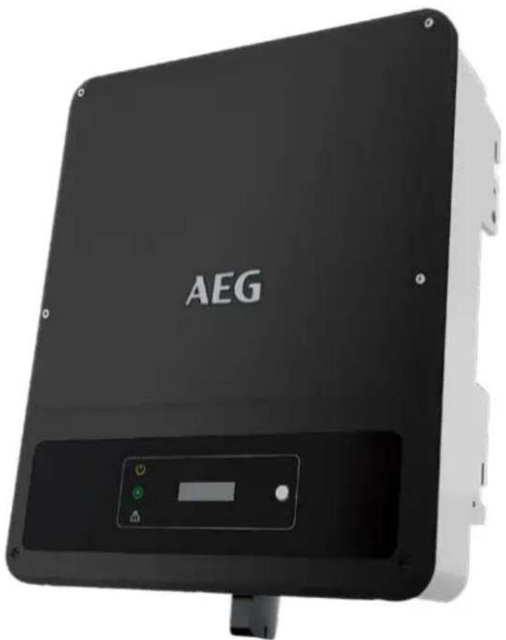
natural_image
Black AEG industrial sensor device with control panel and indicator lights (no readable text or symbols beyond branding)INVERTER SERIES:
AS-IR02-2
Thank you for choosing the reliability of AEG grid-tied solar inverters. This guide is intended for distributors and installers involved in the planning, installation and commissioning of photovoltaic systems. AEG grid-tied solar inverters are tested and approved by acknowledged independent certification authorities and can only be installed by qualified professional companies. Please observe the standards and regulations applying to photovoltaic systems in the relevant countries, as well as the rules of the employers' liability insurance associations for accident protection. Failure to comply with these can result in major injuries and damage. Keep this guide in a safe place for further reference as it contains important information for product care, maintenance and disposal.
Table of contents | Съдържание | | Obsah | Indholdsfortegnelse | Inhaltsverzeichnis | Півакаєs пөріехоме́вων | Tabla de contenidos | Sisukord | Sisällysluettelo | Table des matières | Sadržaj | Tartalomjegyzék | Índice dei contenuti | Satura rădītājs | Turinys | Inhoudsopgave | Spis treści | Índice | Cuprins | Obsah | Kazalo | Innehållsförteckning |
- Safety precautions ...2 FR ...30 SK ...60
EN ...3 HR ...33 SL ...63
BG ...6 HU ...37 SV ...66
CZ ...9 IT ...39 2. Product introduction ...69
DA ...12 LT ...42 3. Inverter installation ...70
DE ...15 LV ...45 4. Electrical connection ...73
EL ...18 NL ...48 5. Power on / off ...80
ES ...21 PL ...51 6. Commissioning ...81
ET ...24 PT ...54 7. Further information ...82
FI ...27 RO ...57
- Safety precautions | Мерки за безопасност | Bezpečnostní opatření | Sikkerhedsforholdsregler | Sicherheitshinweise | Métra профúlaξης | Precauciones de seguridad | Ohutusjuhised | Varotoimenpiteet | Consignes de sécurité | Sigurnosne mjere opreza | Biztonsági óvintézkedések | Misure di sicurezza | Saugos reikalavimai | Drošības pasākumi | Veiligheidsmaatregelen | Środki ostrożności | Precauções de segurança | Atenționări privind siguranța | Bezpečnostné opatrenia | Varnostni ukrepi | Säkerhetsföreskrifter
1.1 General Disclaimer
- The information in this quick installation guide is subject to change due to product updates or other reasons. This guide cannot replace the product labels or the safety precautions in the user manual unless otherwise specified. All descriptions here are for guidance only.
- Before installations, read through the quick installation guide. For additional information, please see the user manual.
- All operations should be performed by trained and knowledgeable technicians who are familiar with local standards and safety regulations.
- Check the deliverables for correct model, complete contents, and intact appearance. Contact the manufacturer if any damage is found or any component is missing.
- Use insulating tools and wear personal protective equipment when operating the equipment to ensure personal safety. Wear anti-static gloves, clothes, and wrist strip when touching electronic components to protect the inverter from damage. The manufacturer shall not be liable for any damage caused by static electricity.
- Strictly follow the installation, operation, and configuration instructions in this guide and user manual. The manufacturer shall not be liable for equipment damage or personal injury if you do not follow the instructions. For more warranty details, please visit https://www.aeg-industrialsolar.de/service/downloads/
1.2 Safety Disclaimer

Warning
DC Side:
- Ensure the component frames and the bracket system are securely grounded.
- Connect the DC cables using the delivered PV connectors. The manufacturer shall not be liable for equipment damage if other connectors are used.
- Ensure the DC cables are connected tightly, securely, and correctly. Inappropriate wiring may cause poor contacts or high impedances, and damage the inverter.
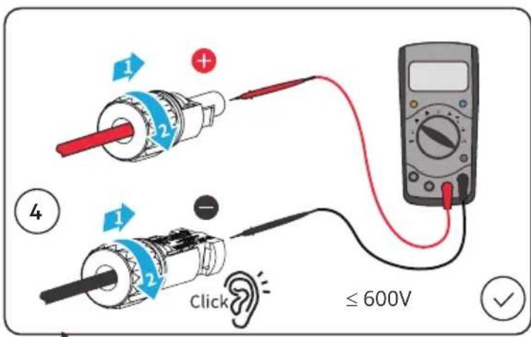
- Measure the DC cable using the multimeter to avoid reverse polarity connection. Also, the voltage should be under the max DC input voltage. The manufacturer shall not be liable for the damage caused by reverse connection and extremely high voltage.
- The PV modules used with the inverter must have an IEC61730 class A rating.
AC Side:
- The voltage and frequency at the connecting point should meet the on-grid requirements.
- Additional protective devices like circuit breakers or fuses are recommended on the AC side. Specification of the protective device should be at least 1.25 times the rated AC output rated current.
- PE cable of the inverter must be connected firmly. The resistance between the neutral wire and the earth cable is less than 10 .
- You are recommended to use copper cables as AC output cables. If you prefer aluminum cables, remember to use copper to aluminum adapter terminals.
Product :
- Do not apply mechanical load to the terminals, otherwise the terminals can be damaged.
- All labels and warning marks should be visible after the installation. Do not scrawl, damage, or cover any label on the device.
- Unauthorized dismantling or modification may damage the equipment, the damage is not covered under the warranty.
- Install the inverter away from high magnetic field to avoid electromagnetic interference. If there is any radio or wireless communication equipment below 30MHz near the inverter, you have to:
• Install the inverter at least 30m far away from the wireless equipment.
- Add a low pass EMI filter or a multi winding ferrite core to the DC input cable or AC output cable of the inverter.
- Warning labels on the inverter are as follows.
 | HIGH VOLTAGE HAZARD.Disconnect all incoming power and turn off the product before working on it. | 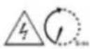 | Delayed discharge. Wait 5 minutes after power off until the components are completely discharged. |
 | Read through the guide before working on this device. |  | Potential risks exist. Wear proper PPE before any operations. |
 | High-temperature hazard. Do not touch the product under operation to avoid being burnt. |  | Grounding point. Indicates the position for connecting the PE cable. |
 | CE marking |  | Do not dispose of the inverter as household waste.Discard the product in compliance with local laws and regulations, or send it back to the manufacturer. |
1.3 Check before power-on
| No | Check item | |
| 1 | ☐ | The product is firmly installed at a clean place that is well-ventilated and easy-to-operate. |
| 2 | ☐ | The PE, DC input, AC output, and communication cables are connected correctly and securely. |
| 3 | ☐ | Cable ties are intact, routed properly and evenly. |
| 4 | ☐ | Unused ports and terminals are sealed. |
| 5 | ☐ | The voltage and frequency at the connection point meet the inverter grid connection requirements. |
1.4 EU Declaration of Conformity
Solar Solutions hereby declares that the inverter with wireless communication modules sold in the European market meets the requirements of the following directives:
• Radio Equipment Directive 2014/53/EU (RED)
• Restrictions of Hazardous Substances Directive 2011/65/EU and (EU) 2015/863 (RoHS)
• Waste Electrical and Electronic Equipment 2012/19/EU
• Registration, Evaluation, Authorisation and Restriction of Chemicals (EC) No 1907/2006 (REACH)
Solar Solutions hereby declares that the inverter without wireless communication modules sold in the European market meets the requirements of the following directives:
• Electromagnetic compatibility Directive 2014/30/EU (EMC)
• Electrical Apparatus Low Voltage Directive 2014/35/EU (LVD)
• Restrictions of Hazardous Substances Directive 2011/65/EU and (EU) 2015/863 (RoHS)
• Waste Electrical and Electronic Equipment 2012/19/EU
• Registration, Evaluation, Authorization and Restriction of Chemicals (EC) No 1907/2006 (REACH)
You can download the EU Declaration of Conformity on https://www.aeg-industrialsolar.de/service/downloads/.
1.5. LED Indicators
| Indicator | Status | Description |
 Power Power | ON = WiFi is connected/active. | |
| BLINK 1 = WiFi system is resetting. | ||
| BLINK 2 = WiFi not connect to the router. | ||
| BLINK 4 = WiFi server problem. | ||
| BLINK = RS485 is connected. | ||
| OFF = WiFi is not active. | ||
| [00SH]Operating | ON = The inverter is feeding power. | |
| OFF = The inverter is not feeding power at the moment. | ||
| [YS47]Faulty | ON = A fault has occurred. | |
| OFF = No fault. |
https://www.aeg-industrialsolar.de/service/downloads/.
https://www.aeg-industrialsolar.de/service/downloads/.
1.2 Vyhlásenie o bezpečnosti

Upozornenie
https://www.aeg-industrialsolar.de/service/downloads/.
WiFi/LAN/4G Communication
Module Port or RS485
Communication Cable Port
DRED/CT/Remote
-
Shutdown Communication Cable Port
-
AC Output Terminal 6. Indicator
-
LCD
8.
Button
9.
PE Terminal
- Mounting Plate 11. Heat Sink
Dimensions | Размерi | Rozměry | Dimensioner | Abmessungen | Διαστάσεις | Dimensiones | Möötmed | Mitat | Dimensions | Dimenzije | Méretek | Dimensioni | Matmenys | Dimensijas | Afmetingen | Wymiary | Dimensões | Dimensiuni | Rozmery | Mere | Mått

- Inverter Installation | Монтаж на инвертора | Instalace měniče | Inverterinstallation | Montage und Installation | Еγκατάσταση μετατροπέα | Instalación del inversor | Inverteri paigaldamine | Inverterin asennus | Installation de l'onduleur | Instalacija pretvarača | Az inverter telepítése | Montaggio dell'inverter | Keitiklio montavimas | Invertora uzstādīšana | Installatie van de | Montaż falownika | Instalação do inversor | Instalarea invertorului | Inštalácia meniča | Namestitev pretvornika | Installation av växelriktaren
PACKING LIST

× 1

× 1

x N

x 2

x 1

x 1

× N × N


× N × 1

N = Quantity depends on the inverter model
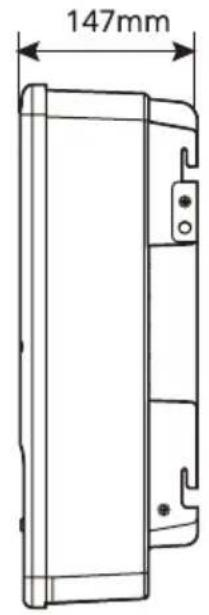
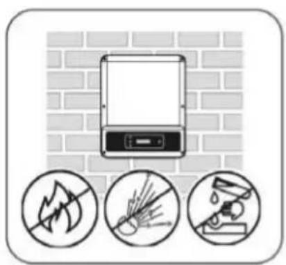
Space Requirements | Изисквания за пространството | Požadavky na místo | Pladskrav | Platzbedarf | Аптаітнєєих distingu | Requisitos de espacio | Nõuded ruumile | Tilavaatimukset | Espace nécessaire | Potreban prostor | Helyszükséglet | Spazio necessario | Erdvès reikalavimai | Prasības attiecibā uz vietu | Ruimtevereisten | Wymagania przestrzenne | Requisitos de espaço | Cerințe referitoare la spațiu | Požiadavky na priestor | Potreben prostor | Utrymmeskrav
natural_image
Illustration of a mounted device with three circular icons below showing no text or symbols (no readable text or labels)


natural_image
Simple line drawing of a solar panel mounted on a wall with sunlight symbol and checkmark (no text or labels)
natural_image
Diagram showing airflow around a wall with directional arrows and a checkmark (no text or symbols)
natural_image
Diagram of a brick wall with a nail and a circular symbol containing an 'X' (no text or labels)Angle Requirements | Изисквания за ъгъла | Požadavky na úhel | Vinkelkrav | Montagewinkel | Аптаɪτήσεις γωνίας | Requisitos de ángulo | Nõuded kaldenurgale | Kulmavaatimukset | Angle nécessaire | Potreban nagib | Felszerelés szögével szembeni követelmények | Angolo necessario | Kampo reikalavimai | Prasības attiecībā uz leŋki | Hoekvereisten | Wymagania kątowe | Requisitos de ângulos | Cerințe referitoare la înclinare | Požiadavky na uhol | Potrebni koti | Vinkelkrav

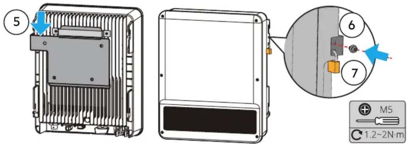
Installing the Inverter | Монтиране на инвертора | Instalace měniče | Installation af inverteren | Wechselrichter montieren | Еуката́σταση του μετατροπέα | Instalación del inversor | Inverteri paigaldamine | Inverterin asentaminen | Installation de l'onduleur | Instalacija pretvarača | Az inverter telepítése | Montaggio dell'inverter | Keitiklio montavimas | Invertora uzstādīšana | De omvormer installeren | Montaż falownika | Instalar o inversor | Instalarea inverterului | Inštalácia meniča | Nameščanje pretvornika | Installation av växelriktaren

- Electrical Connection | Електрическо | Elektrické připojení | El-tilslutning | Elektrischer Anschluss | Нлектрикý σύνδεση | Conexión eléctrica | Elektriline ühendus | Sähköliitäntä | Connexion électrique | Električni spoj | Elektromos csatlakoztatás | Collegamento elettrico | Elektros energijos jungtis | Elektriskais savienojums | Elektrische aansluiting | Podłączenie elektryczne | Ligação elétrica | Conectarea electrică | Elektrické pripojenie | Električni priklop | Elanslutning
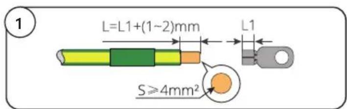
PE Cable | Заземяващ проводник | Kabel PE | PE-kabel | PE-Kabel | Калώδιο γείωσης | Cable PE | PE-kaabel | PE-kaapeli | Câble PE | PE kabel | PE kábel | Cavo PE | Apsauginis jžeminimo kabelis | PE kabelis | PE-kabel | Przewód PE | Cabo PE | Cablu de împământare de protectie | PE kábel | Kabel PE | Jordkabel


AC Cable | Променливотоков проводник | Kabel AC | AC-kabel | AC-Kabel | Калώδιο AC | Cable de CA | Vahelduvvoolukaabel | Vaihtovirtakaapeli | Câble AC | AC kabel | AC kábel | Cavo AC | Kintamosios srovės kabeliai | Mainstrāvas kabelis | AC-kabel | Przewód AC | Cabo CA | Cablu de CA | Kábel striedavého prúdu | Kabel AC | AC-kabel
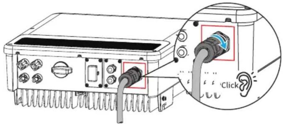
AC-1

or
AC-2 AC-3

natural_image
Technical line drawing of a mechanical connector or fitting (no text or symbols)or

natural_image
Technical line drawing of a mechanical connector or fitting (no text or symbols)AC-1 Connector


AC-2 Connector

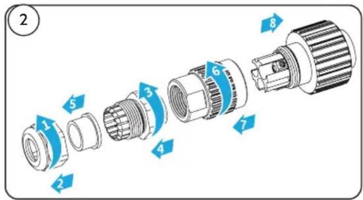


AC-3 Connector
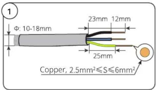


DC Cable | Правотоков проводник | Kabel DC | DC-kabel | DC-Kabel | Калώδιο DC | Cable de CC | Alalisvoolukaabel | Tasavirtakaapeli | Câble DC | DC kabel | DC kábel | Cavo DC | Kintamosios srovès kabelis | Lidzstrāvas kabelis | DC-kabel | Przewód DC | Cabo CC | Cablu de CC | Kábel jednosmerného prúdu | Kabel DC | DC-kabel


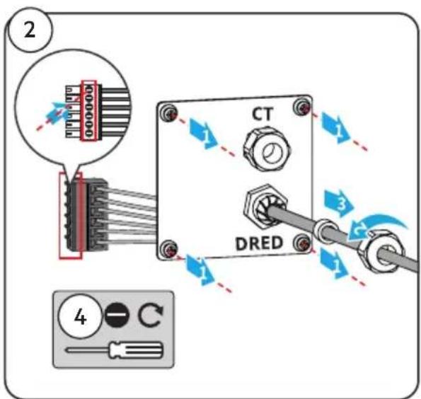
DRED/Remote Shutdown Communication Cable | DRED, дистанционно изключване (RSD) | DRED, Vzdálené vypnutí (RSD) | DRED, fjernnedlukning (RSD) | DRED, Fernabschaltung (RSD) | DRED, Аппомакруσμένη απενεργοποίηση (RSD) | DRED, desconexión remota (RSD) | DRED, kaugseiskamine (RSD) | DRED, etäsammutus (RSD) | DRED, arrêt à distance (RSD) | DRED, daljinsko isključivanje (RSD) | DRED, Távvezérelt leállítás (RSD) | DRED, spegnimento remoto (RSD) | DRED, Nuotolinio išjungimo (RSD) | DRED, Attalā izslēgšana (TVI) | DRED, uitschakelen op afstand (RSD) | DRED, zdalne wyłączanie (RSD) | DRED, encerramento remoto (RSD) | DRED, oprire de la distanță (RSD) | DRED, Vypnutie na dialku (RSD) | DRED, zaustavitev na daljavo (RSD) | DRED, fjärravstängning (RSD)
• DRED: Australia
- Remote Shutdown: Europe
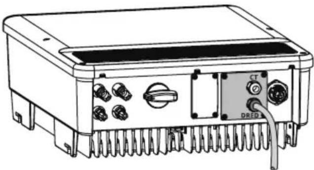
natural_image
Technical line drawing of an electronic device rear panel with connectors and a DRED connector (no text or symbols)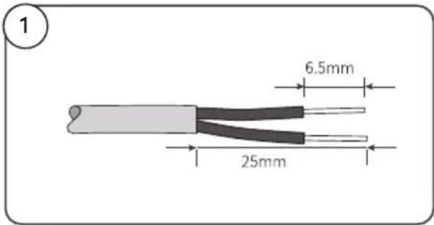

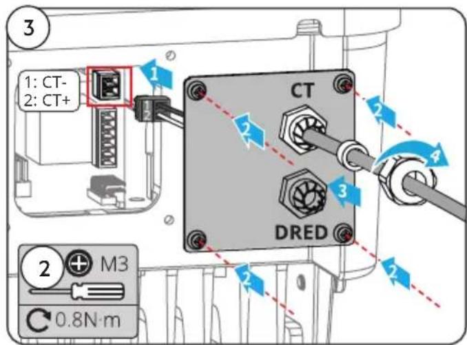
CT Communication Cable | Комуникационен кабел CT | Komunikační kabel CT | CT-kommunikationskabel | CT-Kommunikationskabel | Калώδιο επικοινωνίας CT | Cable de comunicación CT | CT-sidekaabel | CT-tiedonsiirtokaapeli | Câble de communication TC | CT komunikacijski kabel | CT kommunikációs kábel | Cavo di comunicazione CT | CT ryšio kabelis | CT sakaru kabelis | CT-communicatiekabel | Przewód komunikacyjny CT | Cabo de comunicação CT | Cablu de comunicare TC | Komunikačný kábel CT | Komunikacijski kabel CT | CT kommunikationskabel

natural_image
Technical line drawing of an electronic device with ports and connectors (no text or symbols)

RS485 Communication Cable | Комуникационен кабел RS485 | Komunikační kabel RS485 | RS485-kommunikationskabel | RS-485-Kommunikationskabel | Калώδιο επικοινωνίας RS485 | Cable de comunicación RS485 | RS485 sidekaabel | RS485-tiedonsiirtokaapeli | Câble de communication RS485 | RS485 komunikacijski kabel | RS485 kommunikációs kábel | Cavo di comunicazione RS485 | RS485 ryšio kabelis | RS485 sakaru kabelis | RS485-communicatiekabel | Przewód komunikacyjny RS485 | Cabo de comunicação RS485 | Cablu de comunicare RS485 | Komunikačný kábel RS485 | Komunikacijski kabel RS485 | RS485 kommunikationskabel

Communication Module | Комуникационен модул | Komunikační modul | Kommunikationsmodul | Kommunikationsmodul | Mováđa επικοινωνίας | Módulo de comunicación | Sidemoodul | Tiedonsiirtomoduuli | Module de communication | Komunikacijski modul | Kommunikációs modul | Modulo di comunicazione | Ryšio modulis | Sakaru modulis | Communicatiemodule | Moduł komunikacyjny | Módulo de comunicação | Modul de comunicare | Komunikačný modul | Komunikacijski modul | Kommunikationsmodul
WiFi kit, 4G kit, LAN kit, GPRS, Wi-Fi/LAN Kit module: optional.

natural_image
Technical line drawing of an electronic device rear panel with connectors and a highlighted component (no text or symbols)- Power On and Off | Включване и изключване | Zapnutí a vypnutí | Indkobling og frakobling af strømmen | Gerät ein- und ausschalten | Everyottoínon kai atteveryottoínon | Encendido y apagado | Toide sisse ja välja | Virran kytkeminen päälle ja pois päältä | Mise sous tension et hors tension | Uključivanje i isključivanje napajanja | Be-/kikapcsolás | Accensione e spegnimento | Maitinimo jjungimas (ON) ir išjungimas (OFF) | leslēgšana un izslēgšana | Stroom in- en uitschakelen | Włączenie i wyłączenie | Ligar e desligar a alimentação elétrica | Pornirea și oprirea | Zapnuté a vypnuté napájanie | Vklop in izklop | Start och avstängning

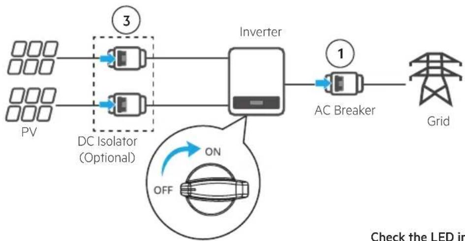
flowchart
graph LR
    A["PV"] --> B["DC Isolator (Optional)"]
    C["3"] --> D["Inverter"]
    E["1"] --> F["AC Breaker"]
    F --> G["Grid"]
    H["ON OFF"] --> I["LED System"]
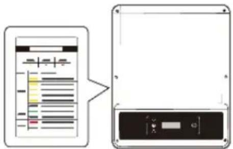
Check the LED indicators

flowchart
graph LR
    A["Turn on"] --> B["31"]
    B --> C["2"]
    D["Turn off"] --> E["31"]
    E --> F["4"]
- Commissioning | Въвеждане в експлоатация | Uvedení do provozu | Idriftsættelse | Inbetriebnahme | Θέση σε λειτουργία | Puesta en servicio | Kasutusele võtmine | Käyttöönotto | Mise en service | Puštanje u pogon | Üzembe helyezés | Messa in servizio | Paleidimas eksploatacijai | levadīšana ekspluatācijā | Inbedrijfstelling | Uruchomienie | Colocação em funcionamento | Punerea în funcțiune | Uvedenie do prevádzky | Izročanje v obratovanje | Driftsättning
Commissioning via LCD | Въвеждане в експлоатация чрез LCD | Uvedení do provozu pomocí LCD | Idriftsættelse via LCD | Inbetriebnahme über das LCD | Θέση σε λειτουργία μέσω LCD | Puesta en servicio mediante LCD | Kasutusele võtmine vedelkristallekraani kaudu | Käyttöönotto LCD:n kautta | Mise en service via l'écran LCD | Puštanje u pogon preko LCD-a | Üzembe helyezés LCD-n keresztül | Messa in servizio tramite LCD | Paleidimas eksploatacijai naudojant LCD | levadišana ekspluatācijā caur LCD | Inbedrijfstelling via LCD-display | Uruchomienie przez LCD | Colocação em funcionamento através do LCD | Punerea în funcțiune prin intermediul ecranului LCD | Uvedenie do prevádzky cez LCD | Izročanje v obratovanje s pomočjo zaslona LCD | Driftsättning via LCD-skärm

flowchart
graph TD
    A["Select Country/Region"] -->|2s long press| B["Country code 1"]
    B --> C["Country code 2"]
    D["Normal Pac=2595.5W"] -->|20s wait| C
For WI-FI Configuration refer to: | За WI-FI konfiguraçia вижте: | Konfigurace WI-FI viz: | For WI-FI-konfiguration se: | Informationen zur WI-FI-Konfiguration finden Sie unter: | Για τη ρύθμιση παραμέτρων WI-FI, ανατρέξτε στο: | Para la configuración de WI-FI, consulte: | WI-FI konfiguratsiooni kohta vaadake: | Katso WI-FI-asetukset kohdasta: | Pour la configuration WI-FI, reportez-vous à: | Za WI-FI konfiguraciju pogledajte: | A WI-FI konfigurációval kapcsolatban lásd: | Per la Configurazione WI-FI fare riferimento a: | Norèdami sužinoti apie WI-FI konfigūraciją, žr: | WI-FI konfigurāciju skatiet sadaļā: | Raadpleeg voor WI-FI-configuratie: | W przypadku konfiguracji WI-FI patrz: | Para configuração WI-FI consulte: | Pentru configurarea WI-FI, consultați: | Informácie o konfigurácii WI-FI nájdete v časti: | Za konfiguracijo WI-FI glejte: | För WI-FI-konfiguration, se:
„WiFi Configuration Guide“

Monitoring via Portal | Наблюдаване през Portal | Monitorování pomocí Portal | Overvågning via Portal | Überwachung übers Portal | Епітнірнош мёсш Portal | Supervisión mediante Portal | Jälgimine portaali kaudu | Seuranta Portal -sovelluksen kautta | Surveillance via portail | Nadzor preko Portal | Felügyelet Portal keresztül | Monitoraggio tramite Portale | Stebėjimas naudojant „Portal“ | Uzraudzība, izmantojot Portal | Monitoring via Portal | Monitorowanie przez Portal | Monitorização através Portal | Monitorizarea prin Portal | Monitorovanie cez portálu | Nadzor preko Portal | Övervakning via Portal:
https://www.pvsolarportal.com/home/login
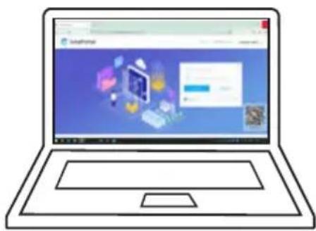
natural_image
Illustration of a laptop with a web interface displayed on its screen (no text or symbols visible)SolarPortal


natural_image
Blue square icon with a white circular background containing six solar panels (no text or symbols)- Further information | Допълнителна информация | Další informace | Yderligere information | Weitere Informationen | Пερισσότερες πληροφορίες | Más información | Lisateave | Lisätietoja | Plus d'informations | Dodatne informacije | További információ | Ulteriori informazioni | Papildinformácija | Daugiau informacijos | Meer informatie | Dalsze informacje | Mais informações | Informații suplimentare | Ďalšie informácie | Dodatne informacije | Ytterligare information
For more detailed instructions see | За по-подробни инструкции вижте: | Podrobnější pokyny viz: | For mere detaljerede instruktioner se: | Ausführlichere Anweisungen finden Sie unter: | Гіа пію авалутикές обнýíєς δείτε: | Para obtener instrucciones más detalladas, consulte: | Üksikasjalikumad juhised leiate: | Katso tarkemmat ohjeet: | Pour des instructions plus détaillées, voir : | Za detaljnije upute pogledajte: | Részletesebb utasításokért lásd: | Per istruzioni più dettagliate si veda: | Išsamesnių instrukciju ieškokite: | Sīkākus norādījumus skatiet: | Zie voor meer gedetailleerde instructies: | Aby uzyskać bardziej szczegółowe instrukcje, zobacz: | Para instruções mais detalhadas, consulte: | Pentru instructiuni mai detaliate vezi: | Podrobnejšie pokyny nájdete v: | Za podrobnejša navodila si oglejte: | För mer detaljerade instruktioner se:
www.aeg-industrialsolar.de/solar-inverters/ www.aeg-industrialsolar.de/service/downloads/
(Choose the appropriate model | Изберете подходящия модел | Vyberte si vhodný model | Vælg den rigtige model | Wählen Sie das passende Modell | Επιλέξτε το κατάλληλο μοντέλο | Elige el modelo adecuado | Valige sobiv mudel | Valitse sopiva malli | Choisissez le modèle approprié | Odaberite odgovarajući model | Válassza ki a megfelelő modellt | Scegliere il modello appropriato | Izvēlieties atbilstošo modeli | Pasirinkite tinkamą modelj | Kies het juiste model | Escolha o modelo apropriado | Alege modelul potrivit | Vyberte si vhodný model | Izberite ustrezen model | Välj lämplig modell)
NOTES
natural_image
Exterior view of a black AEG industrial control unit (no visible text or symbols beyond branding)Solar Solutions Products BV
Finlandlaan 1 2391PV Hazerswoude-Dorp The Netherlands
service@aeg-industrialsolar.de | www.aeg-industrialsolar.de
AEG is a registered trademark used under license from AB Electrolux (publ).

- Table of contents | Съдържание | | Obsah | Indholdsfortegnelse | Inhaltsverzeichnis | Півакаєs пөріехоме́вων | Tabla de contenidos | Sisukord | Sisällysluettelo | Table des matières | Sadržaj | Tartalomjegyzék | Índice dei contenuti | Satura rădītājs | Turinys | Inhoudsopgave | Spis treści | Índice | Cuprins | Obsah | Kazalo | Innehållsförteckning |
- General Disclaimer
- Safety Disclaimer
- Warning
- DC Side:
- AC Side:
- Product :
- Check before power-on
- EU Declaration of Conformity
- LED Indicators
- Vyhlásenie o bezpečnosti
- Upozornenie
- NOTES
Brand : AEG
Model : AS-IR02-6000-2
Category : Solar panel