HI 4E7L0S-80 - Dishwasher HOOVER - Free user manual and instructions
Find the device manual for free HI 4E7L0S-80 HOOVER in PDF.

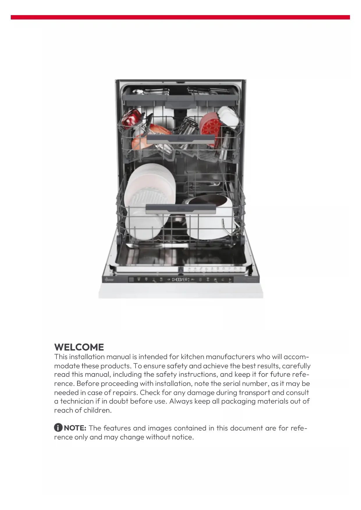


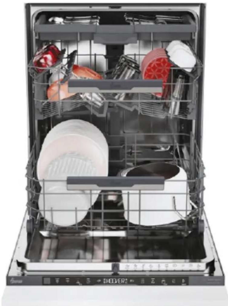
| Product type | Built-in dishwasher |
| Brand | Hoover |
| Model | HI 4E7L0S-80 |
| Dimensions (W × D × H) | 598 × 555 × 818-898 mm |
| Installation dimensions (W × D × H) | Min. 555 × 600 × 820 mm |
| Adjustable height | Yes, from 818 to 898 mm |
| Maximum kitchen panel weight | 9 kg |
| Required water pressure | 0.08 – 1 MPa |
| Power cable length | ~1500 mm |
| Water inlet hose length | ~1700 mm |
| Drain hose length | ~1350 mm |
| Feet adjustment | Yes (front and rear) |
| Tilt adjustment | Yes |
| Anti-vapor strip supplied | Yes |
| Anti-overflow device | Yes |
| Side attachment to cabinets | Yes |
| Attachment to worktop | Yes (depending on material) |
| Included tools | Screws A, B, C, D, E, drilling template |
| Installation | Built-in only |
| Manual pages | 574 |
Frequently Asked Questions - HI 4E7L0S-80 HOOVER
User questions about HI 4E7L0S-80 HOOVER
0 question about this device. Answer the ones you know or ask your own.
Ask a new question about this device
Download the instructions for your Dishwasher in PDF format for free! Find your manual HI 4E7L0S-80 - HOOVER and take your electronic device back in hand. On this page are published all the documents necessary for the use of your device. HI 4E7L0S-80 by HOOVER.
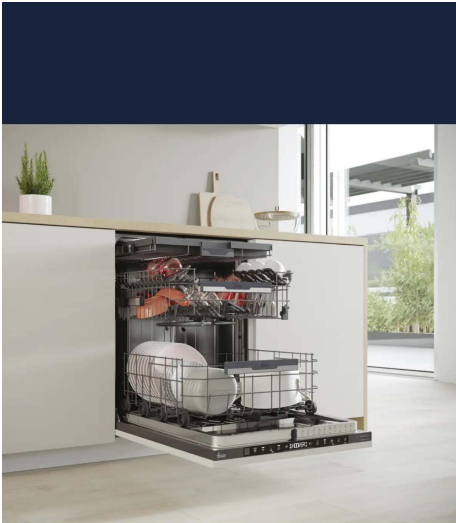
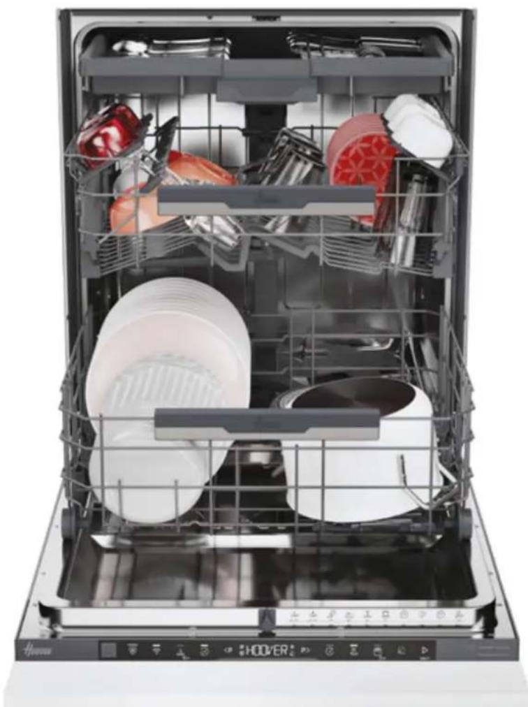
USER MANUAL HI 4E7L0S-80 HOOVER
DOUBLE MOVEMENT HINGES
PERFORMANCE THAT LASTS

EN | IT | FR | DE | ES | GR | NL | PT | SK | PL | CZ | RO | HU
SL | SR | LT | EE | LV | BG | HR | DA | FI | NO | SV | UA | TR

WELCOME
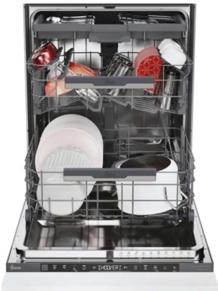
This installation manual is intended for kitchen manufacturers who will accommodate these products. To ensure safety and achieve the best results, carefully read this manual, including the safety instructions, and keep it for future reference. Before proceeding with installation, note the serial number, as it may be needed in case of repairs. Check for any damage during transport and consult a technician if in doubt before use. Always keep all packaging materials out of reach of children.
NOTE: The features and images contained in this document are for reference only and may change without notice.
Index
1 safety notices for installation
2 Where to install the dishwasher p.3
3 Dishwasher dimensions p.4-5
4 Step-by-step installation video p.6
5 installation tools p.6
6 Built-in dimensions p.7
7 Instructions for dishwasher installation p.8 - 17
7.1 Installation of the anti-steam strip
7.2 Height adjustment
7.3 Adjustment of the rear foot
7.4 Adjustment of the front feet height
7.5 Tilt adjustment
7.6 Insertion into the built-in compartment
7.7 Fixing the front feet
7.8 Preparation of the panel
7.9 Installation of the panel
7.10 Fixing the machine to the kitchen
8 Connection to water and electrical network p.18 - 19
8.1 Connection diagram
8.2 Safety devices
9 Delivery to the user p.19
10 Dishwasher disassembly p.19
1 Safety warnings for installation
Observe these directions before beginning the installation of the product. Your safety is very important to us. Please read this information carefully before using the product.
- The installation must be carried out by a qualified technician who must be aware of and comply with the laws in force in the country of installation and the manufacturer's instructions;
- If manufacturer service is required to eliminate faults resulting from improper installation, such service is not covered by the fix;
- Remove the packaging material before operating the appliance;
- After unpacking the product, check that it is not damaged and, in case of problems, contact the service center before proceeding with installation and do not connect it to the power supply;
- A damaged product can cause a short circuit, electric shock, fire hazard, and other dangers;
- Check the packaging for accessories or accompanying materials (envelopes with screws, documents, brochures, etc.) and, if so, remove and store them;
- Incorrect installation may cause harm or injury to people, animals or belonging-gs. The manufacturer cannot be held responsible for such harm or injury;
- Safe use is only guaranteed if installation has been carried out properly according to these instructions. In case of damage due to improper installation, the responsibility lies with the person who installed the product;
- During installation, the appliance must not be connected to the power supply;
- It is recommended to wear protective gloves during installation to avoid cut injuries;
- In case of incorrect installation, tampering with the device and improper connection, the validity of the product warranty will expire;
- Make sure that when the product's power supply cable is completed, it is not accessible;
- After assembly, the power cord must not come into contact with moving parts of kitchen components (such as a drawer) and must not be exposed to mechanical stresses;
- When delivering the product to the end user, the technician must ensure that it has been installed correctly;
-
Do not connect the product to the electrical network until the front panel has been fully installed. Otherwise, there may be an electrical hazard;
• Take care during transport, the product is heavy; -
Before starting the installation, check all the dimensions of the built-in compartment by comparing them with the instructions contained in this manual. Note that it is possible to align the door with the doors of other furniture, even if it exceeds the control panel in height;
- Make sure the installation area is stable and solid;
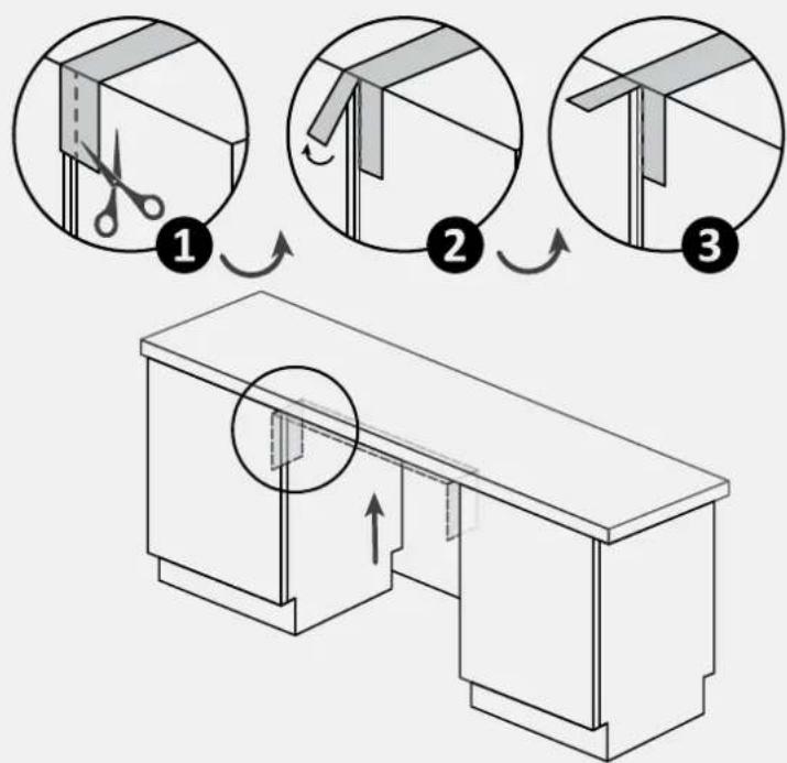
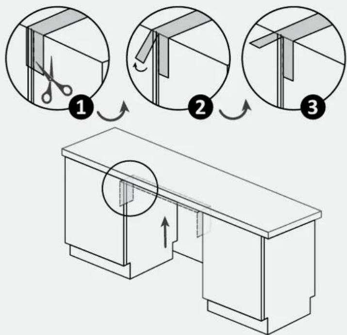
- Apply the protective film, supplied in the installation kit, under the worktop and on surrounding furniture. This film protects the furniture from humidity;
- Be careful when opening and closing the product;
- Incorrect installation can cause the product to tip over;
- The product must be level to function correctly, otherwise the door will not close properly, leading to the escape of hot steam.
Where to install the dishwasher
2
- Install and use this product in a closed, covered, dry, and well-ventilated environment;
- Do not install the product in open environments exposed to atmospheric agents;
• Install the product near an electrical outlet; - Use the product only when placed in a recessed compartment, otherwise you risk injury and burns;
- Do not install the dishwasher under a cooktop;
- Do not install the product near heat sources (radiators, stoves, etc.);
- Do not place the product on carpets or similar surfaces;
- Place the product on a clean, level, and stable surface.
3 Dishwasher dimensions
Dimensions in mm
Front axonometric view of the product

Front axonometric view with kitchen door


WARNING: if the kitchen panel weighs more than 9 kg contact customer service.
Dimensions in mm
Back view

Side view

4 Step-by-step installation video
You can watch the product installation video by scanning the QR Code:

or by clicking this

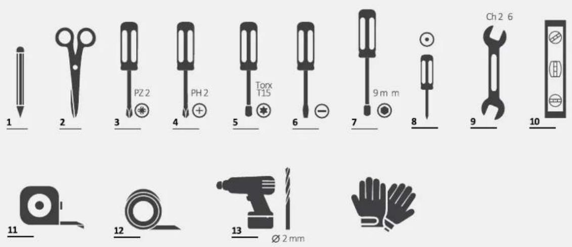
5 Installation tools
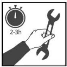
Required tools

Tools provided with the product

Dimensions in mm
Axonometric view

A

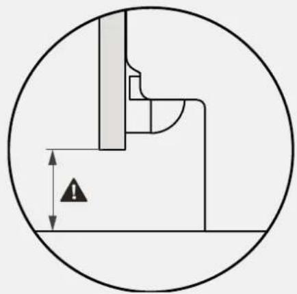
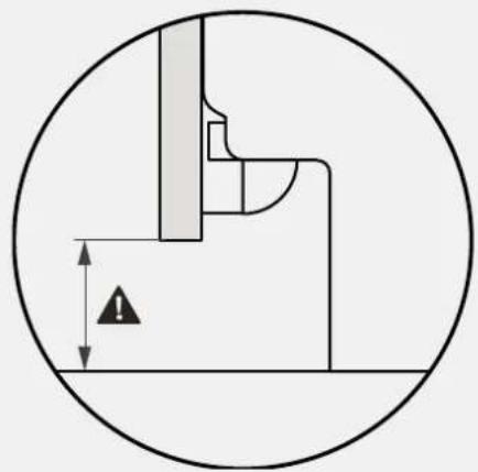
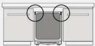
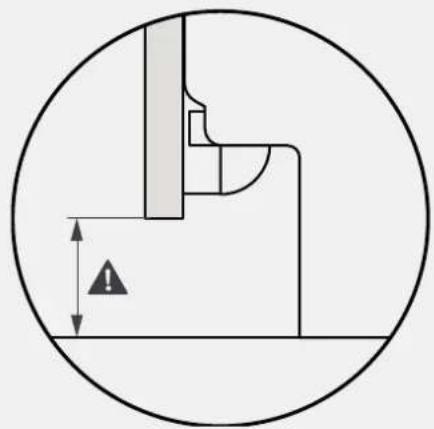
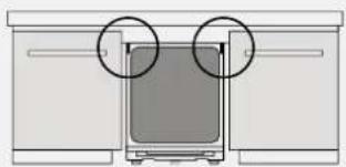
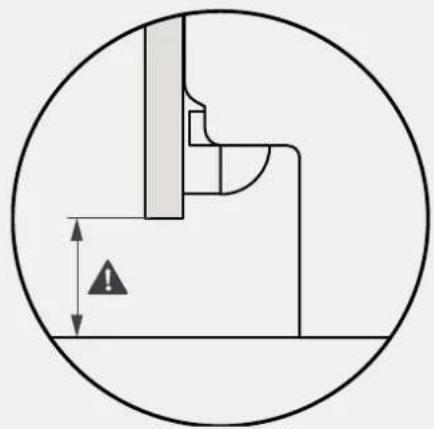
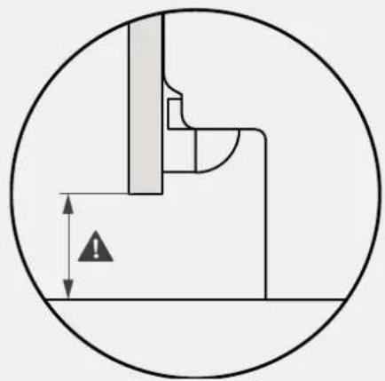
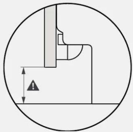
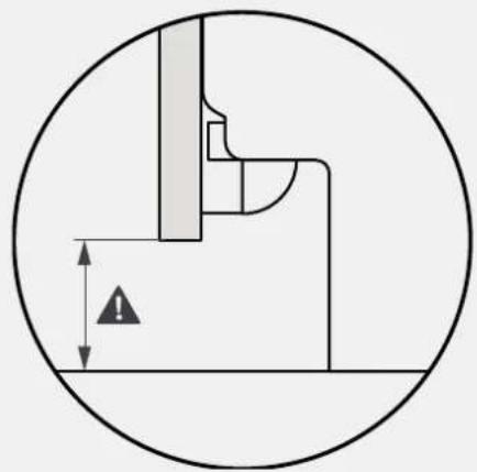
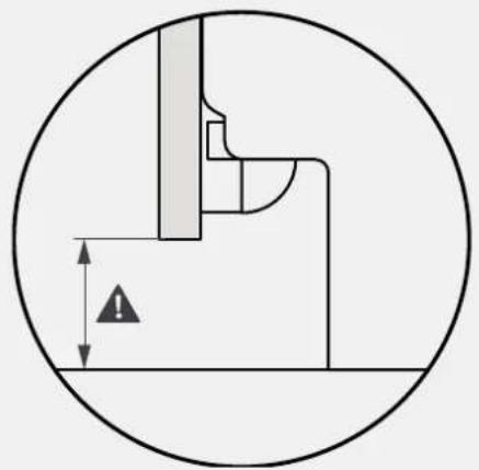
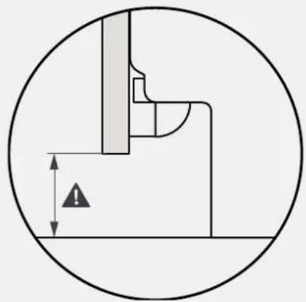
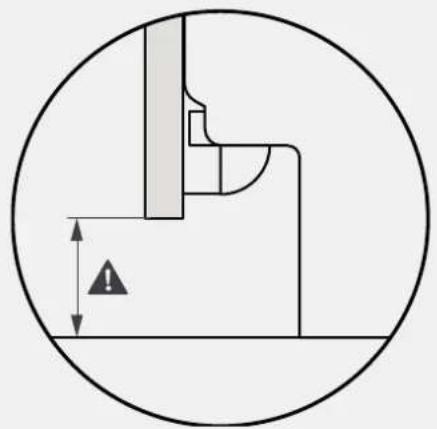
⚠ WARNING: The minimum height of the dishwasher is 818 mm; in this case, the distance between the kitchen door and the floor must be between 90 and 120 mm. If the dishwasher is raised (max. 898 mm), the door-to-floor distance must also increase proportionally, up to a maximum between 170 and 200 mm.
7 Instructions for dishwasher installation
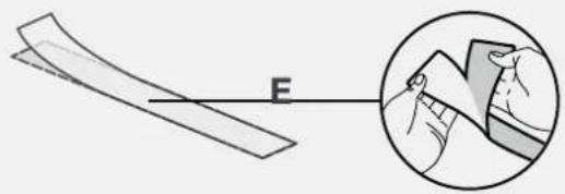
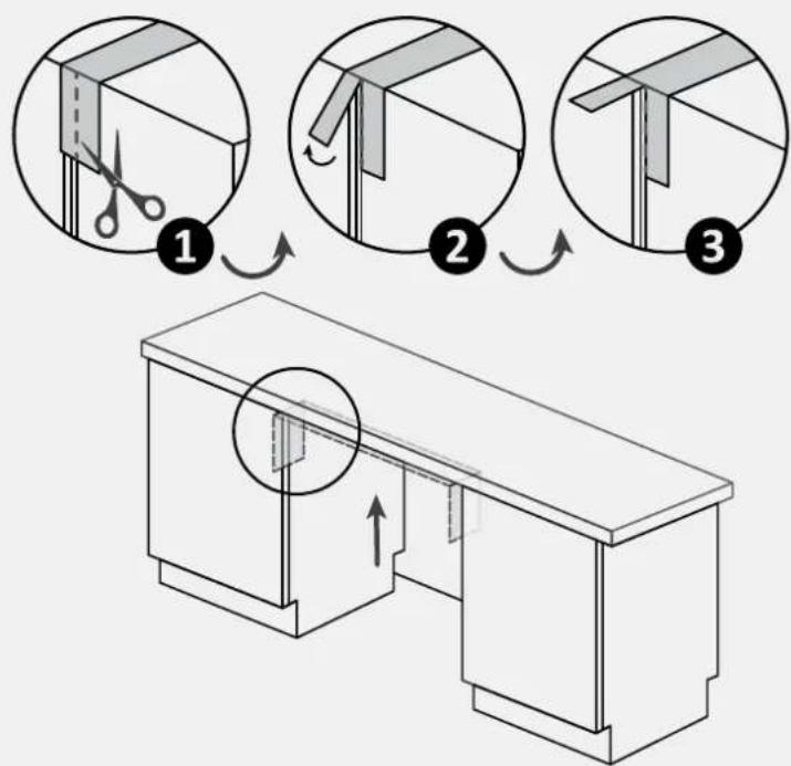
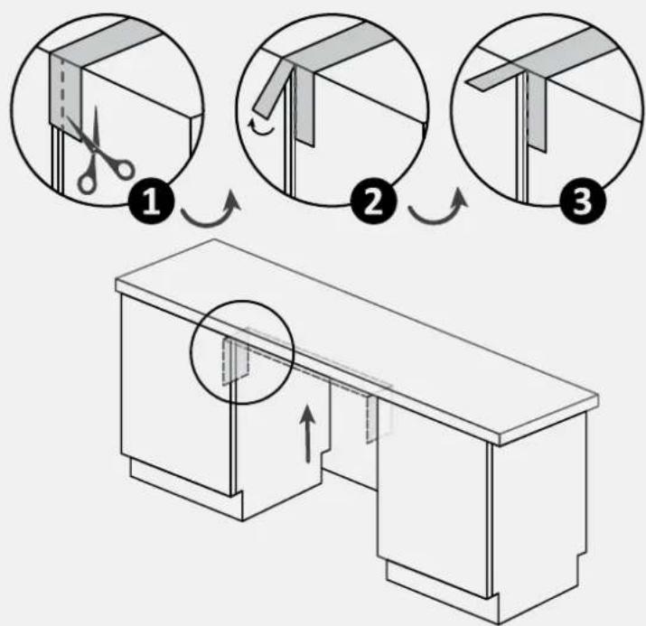
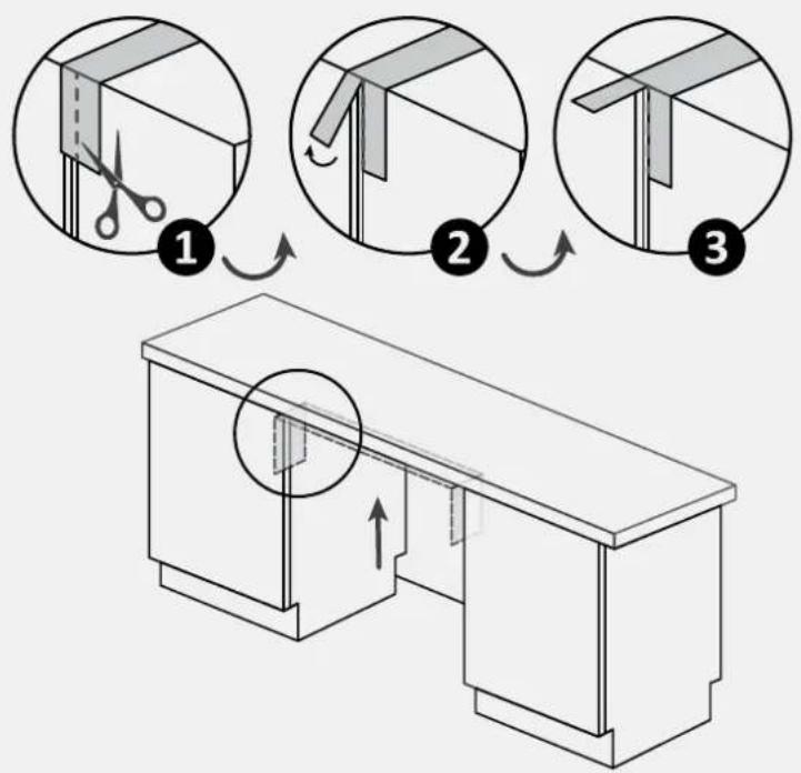
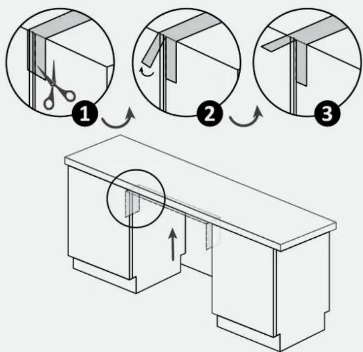
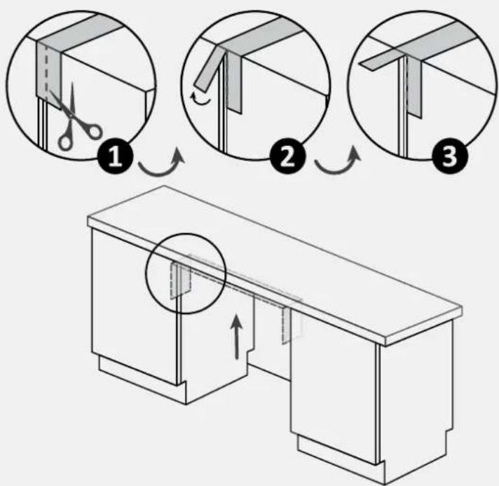
7.1 Steam band installation
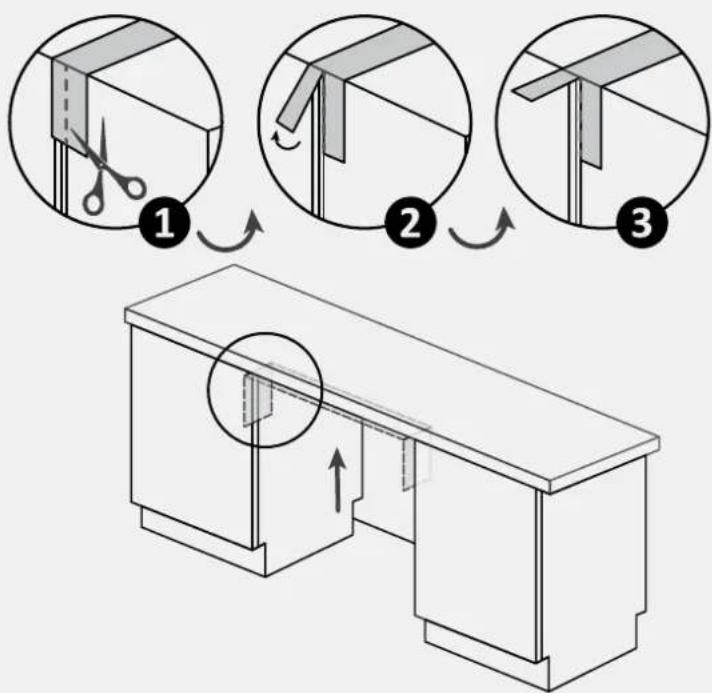
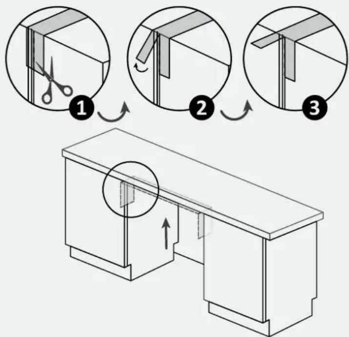
Apply the sticker band under the worktop and to the sides of the adjacent furniture;

7.2 Height adjustment
Incline the dishwasher by raising the back about 10 cm.

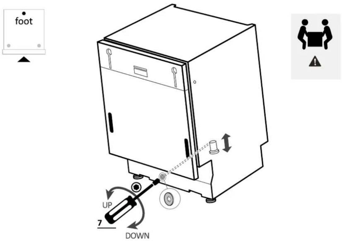
7.3 Rear foot adjustment
Adjust the rear foot height by operating from the front of the machine as indicated below.

7 Instructions for dishwasher installation
7.4 Front feet adjustment
Adjust the front feet directly. If necessary, lift the dishwasher slightly.

7.5 Tilt adjustment
Level the dishwasher by the vertical and horizontal planes.
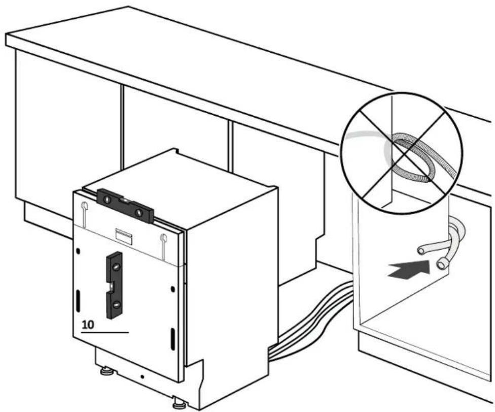
7.6 Insertion into the built-in compartment
Insert the dishwasher into the built-in compartment and check measurements and tolerances.

7.7 Fixing the front feet
After checking all measurements, permanently fix the front feet to prevent them from loosening over time. This operation can also be done after installing the kitchen panel.

7 Instructions for dishwasher installation
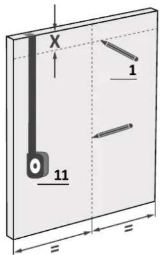
7.8 Panel preparation
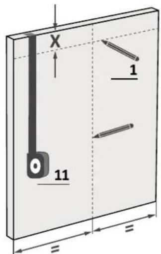
1.
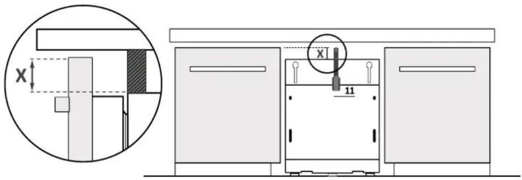
Measure the distance between the top edge of the adjacent doors and the dishwasher;

2.
Transfer the measurement onto the kitchen panel and locate the center;
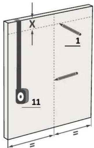
3.
Apply the drilling template anfd follow the structions provided.

7.8 Panel preparation
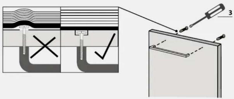
4.
Remove the drilling template and apply the accessories.
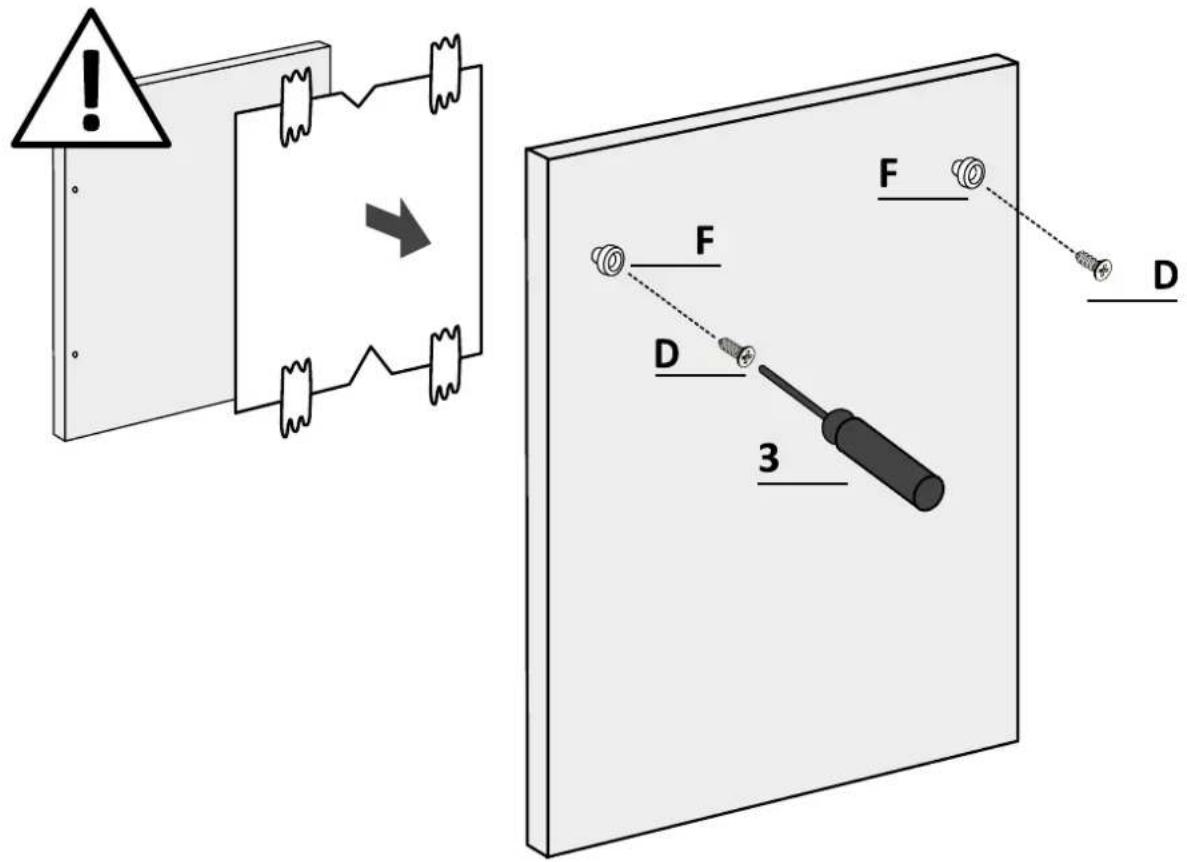
WARNING: Ensure screw heads don't protrude from the panel's rear surface, especially if you install the handle.

7 Instructions for dishwasher installation
Installation of the panel7.9
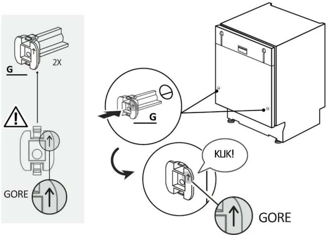
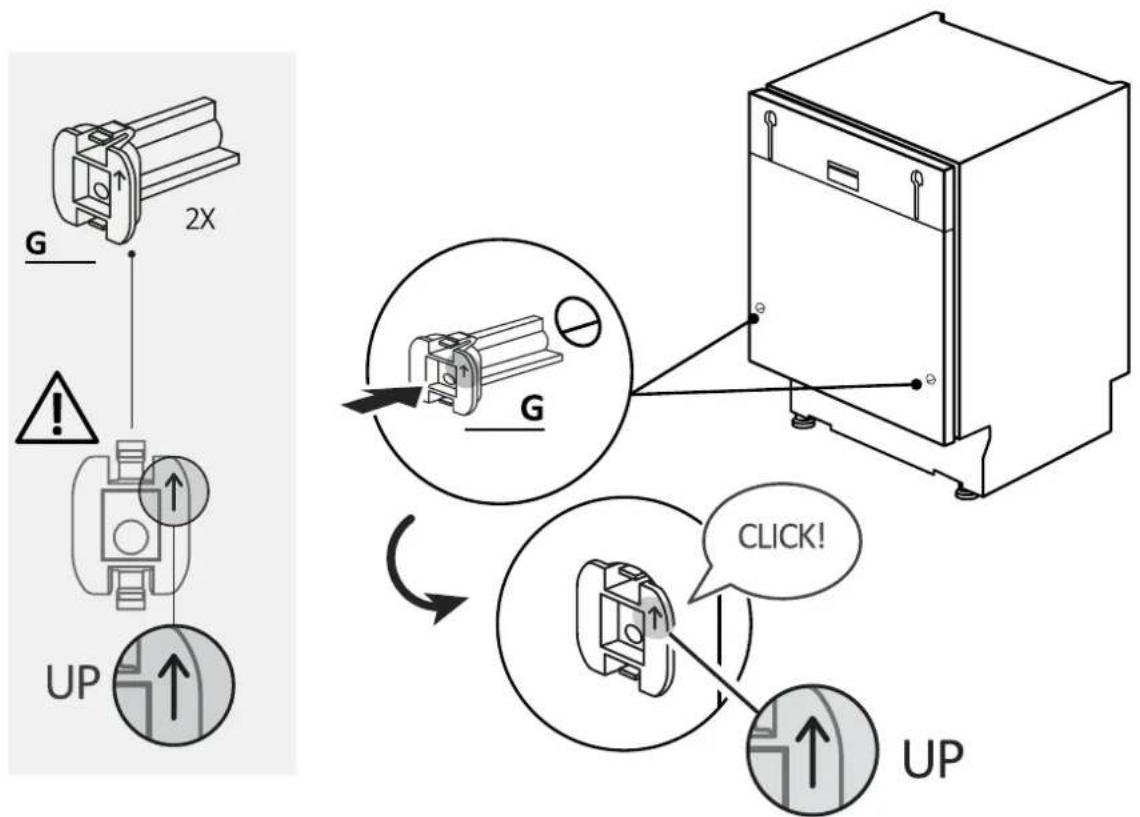
1.
Apply the inserts to the dishwasher, making sure that the components are installed in the correct orientation with the arrow pointing upwards;

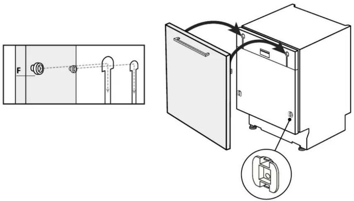
2.
Fix the panel to the lower part of the dishwasher;
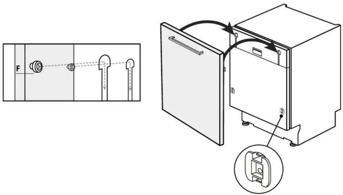
7.9 Installation of the panel
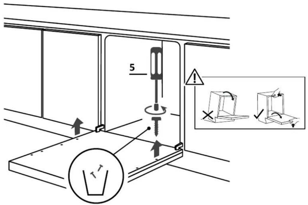
3.
Open the dishwasher door while holding the lower part of the kitchen panel, then unscrew the lower screws;

4.
Make sure the panel is fully inserted (1); fix the kitchen panel to the dishwasher using the supplied screws (2).

7 Instructions for dishwasher installation

⚠ WARNING: Connect the dishwasher now to the water and electrical network, following the instructions in chapter 8.
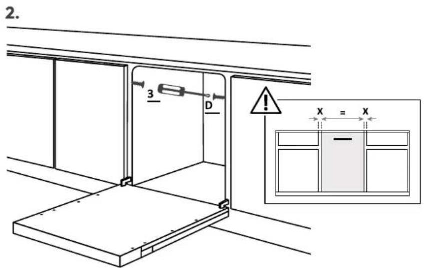
7.10 Fixing the machine to the kitchen
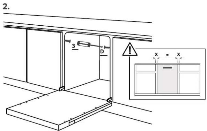
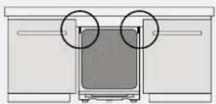
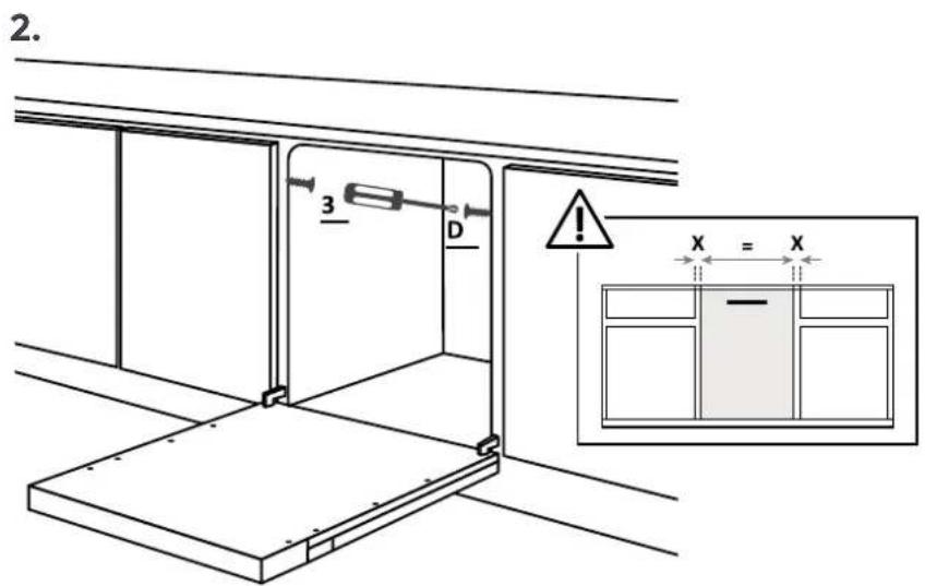
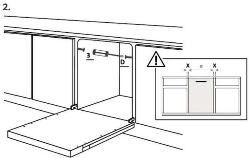
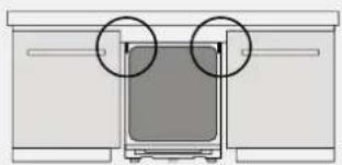
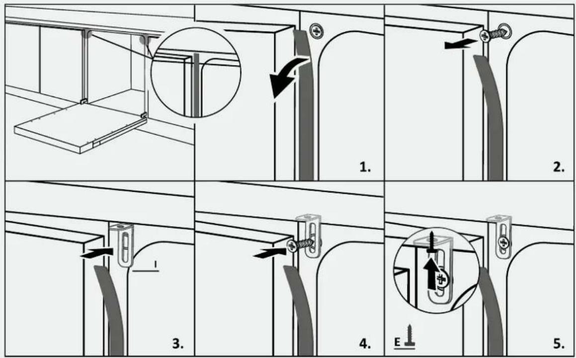
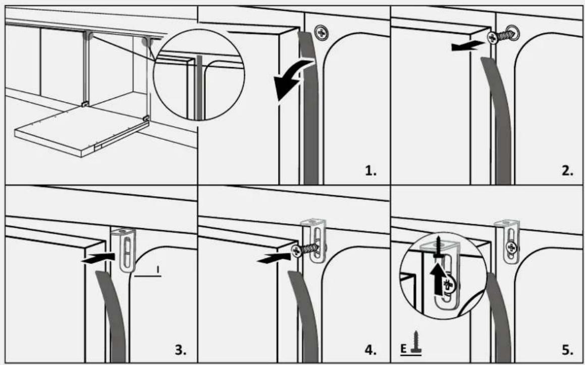
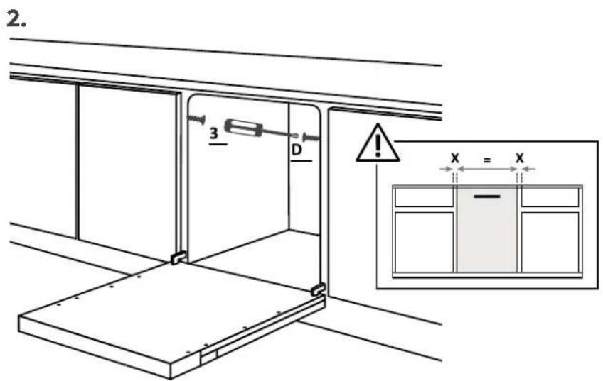
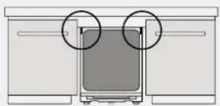
Instructions for fixing the dishwasher laterally to the adjacent cabinets.
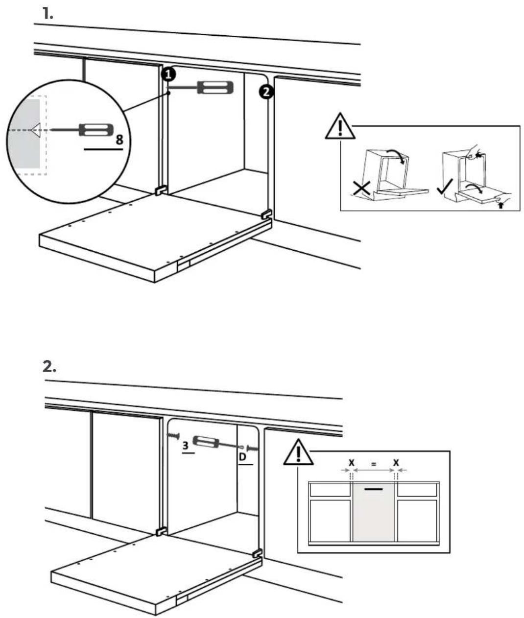


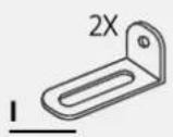
⚠ WARNING: If it is not possible to fix the dishwasher laterally, use the supplied brackets and fix it to the worktop; pay attention if the latter is not made of wood.

8 Drain water and electricity connection
8.1 Connection diagram

Column installation diagram


WARNING: Ensure that the water pressure in between 0.08 Mpa and 1 Mpa.
8.2 Safety devices
All dishwashers are equipped with an anti-overflow safety device which, in the event that the water exceeds the normal level due to a malfunction, automatically blocks the water flow and/or drains the excess water.
See the User Manual for more details.
Delivery to the user
9
At the end of installation:
- Inform the user about essential functions;
- Inform the user about all aspects relevant to safe use and handling;
- Deliver accessories and instructions for use and assembly to the user to be kept with care.
After installation is complete, remove the protective film, tape, and all other packing materials and remove the supplied accessories from inside the product.

NOTE: The actual appearance of the product depends on the model chosen.
Dishwasher disassembly
10
- Disconnect the product from the electrical and water supply;
- Unscrew the fastening screws;
- Slightly lift the product and pull it out completely;
- This product does not damage the furniture, which can also be used with a new appliance.
HOOVER

BENVENUTI

2.


BIENVENUE
5 Installation tools
Outils nécessaires


2.


WILLKOMMEN


2.
7.9 Platteninstallation
3.

BIENVENIDO
3.

7.3 Ajuste del pie trasero
2.


ΚΑΛΩΣ ΗΡΘΑΤΕ

2.


WELKOM

7.2 Hoogteverstelling
7.5 Kantelverstelling
Stel de vaatwasser waterpas af ten opzichte van het verticale en horizontale vlak.

2.


BEMVINDO

3.

2.


VITAJTE
3.

7.5 Nastavenie sklonu
2.
Preneste rozmer na kuchynský panel a určte stred;
3.
7.8 Príprava panelu
4.


WITAMY
Wymiary w mm

3.

7.9 Montaż panelu
3.


VÍTEJTE

3.

7.2 Nastavení výšky
2.
7.8 Příprava panelu
4.
7.9 Instalace panelu
3.


BINE AȚI VENIT
3.
2.


ÜDVÖZÖLJÜK

7.2 Magasságállítás
2.



DOBRODOŠLI
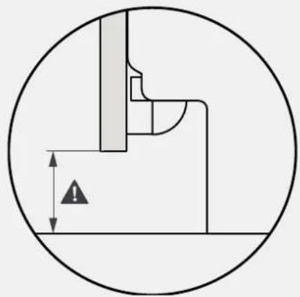
⚠ POZOR: Minimalna višina pomivalnega stroja je 818 mm; v tem primeru mora biti razdalja med kuhinjskimi vrati in tlemi med 90 in 120 mm. Če je pomivalni stroj dvignjen (maks. 898 mm), se mora razdalja med vrati in tlemi sorazmerno povečati do največ med 170 in 200 mm.
3.
2.
Prenesite mero na kuhinjski panel in določite sredino;

3.
Namestite šablono za vrtanje in sledite priloženim navodilom;

7.8 Priprava plošče
4.
Odstranite šablono in namestite dodatke;


⚠ OPOZORILO: Če pomivalnega stroja ne morete pritrditi bočno, uporabite priložene nosilce in ga pritrdite na delovno površino; bodite previdni, če material delovne površine ni les.


DOBRO DOŠLI
Ovo uputstvo za ugradnju namenjeno je proizvođačima kuhinja koji će ugraditi ove proizvode. Da biste osigurali bezbednost i postigli najbolje rezultate, pažljivo pročitajte ovo uputstvo, uključujući bezbednosna uputstva, i čuvajte ga za buduću upotrebu. Pre nego što nastavite sa instalacijom, zabeležite serijski broj, jer može biti potreban u slučaju popravki. Proverite da li ima oštećenja tokom transporta i konsultujte tehničara ako ste u nedoumici pre upotrebe. Uvek držite sve ambalažne materijale van domašaja dece.
i NAPOMENA: Funkcije i slike sadržane u ovom dokumentu služe samo kao referenca i mogu se promeniti bez prethodne najave.
Indeks
ili klikom na ovaj


5 Alati za instalaciju
Potrebni alati


⚠ UPOZORENJE: Minimalna visina mašine za pranje posuđa je 818 mm; u tom slučaju, rastojanje između kuhinjskih vrata i poda mora biti između 90 i 120 mm. Ako je mašina za pranje posuđa podignuta (maks. 898 mm), rastojanje od vrata do poda takođe mora da se poveća proporcionalno, do maksimalno 170 i 200 mm.
7 Uputstvo za ugradnju mašine za pranje sudova
7.1 Instalacija trake protiv pare
7.7 Pričvršćivanje prednjih stopica
Nakon provere svih merenja, trajno pričvrstite prednje stopice kako biste sprečili da se vremenom olabave. Ova radnja se može obaviti i nakon postavljanja kuhinjske ploče.

7 Uputstvo za ugradnju mašine za pranje sudova
7.8 Priprema ploče
1.
Izmerite rastojanje između gornje ivice susednih vrata i mašine za pranje posuđa;
2.
Prenesite meru na kuhinjsku ploču i locirajte centar;
3.
Primenite šablon bušenja i pratite data uputstva.

7.8 Priprema ploče
4.
⚠ UPOZORENJE:Uverite se da glave zavrtanja ne vire sa zadnje strane ploče, naročito ako ugrađujete ručku.

7 Uputstvo za ugradnju mašine za pranje sudova
7.9 Instalacija ploče
1.
Stavite umetke na mašinu za pranje posuđa, vodeći računa da su komponente instalirane u ispravnoj orijentaciji sa strelicom okrenutom nagore;
2.
Pričvrstite ploču na donji deo mašine za pranje posuđa;
7.9 Instalacija ploče
3.
Otvorite vrata mašine za pranje posuđa dok držite donji deo kuhinjske ploče, a zatim odvrnite donje zavrtnje;
4.
Proverite da li je ploča potpuno umetnuta (1); pričvrstite kuhinjsku ploču na mašinu za pranje posuđa pomoću priloženih zavrtanja (2).

⚠ UPOZORENJE: Ako nije moguće bočno pričvrstiti mašinu za pranje posuđa, koristite isporučene nosače i pričvrstite je na radnu površinu; obratite pažnju ako nije napravljena od drveta.
SVEIKI ATVYKE


3.

7.5 Pasvirimo reguliavimas
2.
7 Indaplovès jrengimo nurodymai
7.9 Skydelio montavimas
1.
7.9 Skydelio montavimas
3.
7 Indaplovès jrengimo nurodymai


TERE TULEMAST
Mõõtmed mm
3.

7.5 Kaldenurga reguleerimine
7.7 Esijalgade kinnitamine
2.
7.8 Paneeli ettevalmistamine
4.
7.9 Paneeli paigaldamine
3.


LAIPNI LÜGTI
vai noklikškinot uz šis saites


3.

2.
7.9 Paneeli paigaldamine
3.


ДОБРЕ ДОШЛИ
2.
7.8 Подготовка на панела
4.


DOBRODOŠLI
ili klikom na sljedeći


5 Alati za instalaciju
Potrebni alati

⚠ UPOZORENJE: Minimalna visina perilice posuđa je 818 mm; u tom slučaju udaljenost između kuhinjskih vrata i poda mora biti između 90 i 120 mm. Ako se perilica posuđa podigne (maks. 898 mm), ta se udaljenost također mora proporcionalno povećati, do maksimalno između 170 i 200 mm.
7 Upute za instalaciju perilice posuđa
7.1 Ugradnja parne trake
3.
7.2 Podešavanje visine
7.3 Podešavanje stražnje noge
Podesite visinu stražnje nožice s prednje strane stroja prema uputama.
7 Upute za instalaciju perilice posuđa
7.4 Podešavanje visine prednjih nogu
Djelujte izravno na prednje noge. Ako je potrebno, lagano podignite perilicu posuđa.

7.5 Podešavanje nagiba
Poravnajte perilicu posuđa u vertikalnoj i horizontalnoj ravnini.

7.6 Umetanje u ugradbeni prostor
2.
7.8 Priprema ploče
4.
Uklonite šablonu i postavite dodatke.

⚠️ PAŽNJA: Izbjegavajte da glave vijaka vire na stražnjoj strani panela pri-likom postavljanja ručke.
7 Upute za instalaciju perilice posuđa
7.9 Instalacija panela
1.
Postavite umetke na perilicu posuđa, pazeći da su komponente ugrađene u pravom smjeru, sa strelicom okrenutom prema gore;
2.
Pričvrstite panel na gornji dio perilice posuđa;

7.9 Paneeli paigaldamine
3.
Otvorite vrata perilice posuđa držeći donji dio kuhinjskog panela, zatim odvijte donje vijke;

4.
Provjerite je li panel u potpunosti umetnut (1); pričvrstite kuhinjski panel na perilicu posuđa pomoću priloženih vijaka (2).

7 Upute za instalaciju perilice posuđa


⚠ UPOZORENJE: Ako ne možete bočno učvrstiti perilicu posuđa, upotrijebite priložene nosače i pričvrstite je na radnu površinu; budite oprezni ako materijal radne površine nije drvo.
VELKOMMEN
Mål i mm
Aksonometrijski prikaz

A


3.

7.2 Højdejustering
7.5 Vinkeljustering
2.
7.9 Installation of panelet
1.
Monter indsatsene på opvaskemaskinen, og sørg for, at komponenterne installeres i den korrekte retning med pilen opad;

2.
7.9 Installation of panelet
3.


TERVETULOA
Mitat mm
Aksometrinen näkymä

A


3.

7.2 Korkeussäätö
Kallista astianpesukonetta nostamalla takaosaa noin 10 cm.

7.3 Takajalan säätö
2.
7.9 Paneelin asennus
3.


VELKOMMEN

3.
7.2 Høydejustering
7.5 Vinkeljustering
2.
VÄLKOMMEN

3.

7.2 Höjdjustering
7.5 Vinkeljustering
2.


ЛАСКАВО ПРОСИМО!
або натиснувши це
посилання


2.


HOŞ GELDİNİZ
3.
7.2 Yükseklik ayarı
7.5 Eğim ayarı
2.
7.9 Panel montaji
3.


- WELCOME
- INDEX
- 1 SAFETY WARNINGS FOR INSTALLATION
- OBSERVE THESE DIRECTIONS BEFORE BEGINNING THE INSTALLATION OF THE PRODUCT. YOUR SAFETY IS VERY IMPORTANT TO US. PLEASE READ THIS INFORMATION CAREFULLY BEFORE USING THE PRODUCT
- WHERE TO INSTALL THE DISHWASHER
- 3 DISHWASHER DIMENSIONS
- 4 STEP-BY-STEP INSTALLATION VIDEO
- 5 INSTALLATION TOOLS
- 7 INSTRUCTIONS FOR DISHWASHER INSTALLATION
- 7.1 STEAM BAND INSTALLATION
- 7.2 HEIGHT ADJUSTMENT
- 7.3 REAR FOOT ADJUSTMENT
- 7.4 FRONT FEET ADJUSTMENT
- 7.5 TILT ADJUSTMENT
- 7.6 INSERTION INTO THE BUILT-IN COMPARTMENT
- 7.7 FIXING THE FRONT FEET
- 7.8 PANEL PREPARATION
- 1
- 2
- 3
- INSTALLATION OF THE PANEL7.9
- 7.9 INSTALLATION OF THE PANEL
- 4
- 7.10 FIXING THE MACHINE TO THE KITCHEN
- 8 DRAIN WATER AND ELECTRICITY CONNECTION
- 8.1 CONNECTION DIAGRAM
- 8.2 SAFETY DEVICES
- DELIVERY TO THE USER
- DISHWASHER DISASSEMBLY
- HOOVER
- BENVENUTI
- BIENVENUE
- WILLKOMMEN
- 7.9 PLATTENINSTALLATION
- BIENVENIDO
- 7.3 AJUSTE DEL PIE TRASERO
- ΚΑΛΩΣ ΗΡΘΑΤΕ
- WELKOM
- 7.2 HOOGTEVERSTELLING
- 7.5 KANTELVERSTELLING
- BEMVINDO
- VITAJTE
- 7.5 NASTAVENIE SKLONU
- 7.8 PRÍPRAVA PANELU
- WITAMY
- 7.9 MONTAŻ PANELU
- VÍTEJTE
- 7.2 NASTAVENÍ VÝŠKY
- 7.8 PŘÍPRAVA PANELU
- 7.9 INSTALACE PANELU
- BINE AȚI VENIT
- ÜDVÖZÖLJÜK
- 7.2 MAGASSÁGÁLLÍTÁS
- DOBRODOŠLI
- 7.8 PRIPRAVA PLOŠČE
- DOBRO DOŠLI
- INDEKS
- 5 ALATI ZA INSTALACIJU
- 7 UPUTSTVO ZA UGRADNJU MAŠINE ZA PRANJE SUDOVA
- 7.1 INSTALACIJA TRAKE PROTIV PARE
- 7.7 PRIČVRŠĆIVANJE PREDNJIH STOPICA
- 7.8 PRIPREMA PLOČE
- 7.9 INSTALACIJA PLOČE
- SVEIKI ATVYKE
- 7.5 PASVIRIMO REGULIAVIMAS
- 7 INDAPLOVÈS JRENGIMO NURODYMAI
- 7.9 SKYDELIO MONTAVIMAS
- TERE TULEMAST
- 7.5 KALDENURGA REGULEERIMINE
- 7.7 ESIJALGADE KINNITAMINE
- 7.8 PANEELI ETTEVALMISTAMINE
- 7.9 PANEELI PAIGALDAMINE
- LAIPNI LÜGTI
- ДОБРЕ ДОШЛИ
- 7.8 ПОДГОТОВКА НА ПАНЕЛА
- 7 UPUTE ZA INSTALACIJU PERILICE POSUĐA
- 7.1 UGRADNJA PARNE TRAKE
- 7.2 PODEŠAVANJE VISINE
- 7.3 PODEŠAVANJE STRAŽNJE NOGE
- 7.4 PODEŠAVANJE VISINE PREDNJIH NOGU
- 7.5 PODEŠAVANJE NAGIBA
- 7.6 UMETANJE U UGRADBENI PROSTOR
- 7.9 INSTALACIJA PANELA
- VELKOMMEN
- 7.2 HØJDEJUSTERING
- 7.5 VINKELJUSTERING
- 7.9 INSTALLATION OF PANELET
- TERVETULOA
- 7.2 KORKEUSSÄÄTÖ
- 7.3 TAKAJALAN SÄÄTÖ
- 7.9 PANEELIN ASENNUS
- 7.2 HØYDEJUSTERING
- VÄLKOMMEN
- 7.2 HÖJDJUSTERING
- ЛАСКАВО ПРОСИМО
- HOŞ GELDİNİZ
- 7.2 YÜKSEKLIK AYARI
- 7.5 EĞIM AYARI
- 7.9 PANEL MONTAJI
Brand : HOOVER
Model : HI 4E7L0S-80
Category : Dishwasher