
POWX1800 - Saw PowerPlus - Free user manual and instructions
Find the device manual for free POWX1800 PowerPlus in PDF.
| Product type | Band saw |
| Brand | PowerPlus |
| Model | POWX1800 |
| Supply voltage | 230-240 V~, 50 Hz |
| Power consumption | 350 W (S2-10 min) |
| Motor type | Induction |
| Blade speed | 630 m/min |
| Blade length | 1511 mm |
| Blade width | 6.5 mm |
| Max cut depth | 89 mm |
| Max cut width | 228 mm |
| Table dimensions | 313 x 302 mm |
| Table tilt | 0° to 45° |
| Net weight | 19 kg |
| Dust extraction diameter | 63.5 mm |
| Sound pressure level | 91 dB(A) (K=3) |
| Sound power level | 99 dB(A) (K=3) |
| Warranty | 36 months |
| Intended use | Cross and rip cuts in wood and similar materials (non-professional use) |
| Safety equipment | Blade guard, wheel covers, safety switch |
| Maintenance | Clean regularly, lubricate guides, replace blade and belts if worn |
| Spare parts | Blades, rubber belts, removable table insert, side guides |
| Repairability | Have repaired by an authorized professional, original parts recommended |
Frequently Asked Questions - POWX1800 PowerPlus
User questions about POWX1800 PowerPlus
0 question about this device. Answer the ones you know or ask your own.
Ask a new question about this device
Download the instructions for your Saw in PDF format for free! Find your manual POWX1800 - PowerPlus and take your electronic device back in hand. On this page are published all the documents necessary for the use of your device. POWX1800 by PowerPlus.
USER MANUAL POWX1800 PowerPlus
POWERPLUS HIGH QUALITY TOOLS
POWX1800

NL NEDERLANDS VERTAALDE VERSIE VAN DE ORIGINELE HANDLEIDING
FR FRANÇAIS TRADUCTION DU MODE D'EMPLOI D'ORIGINE
EN ENGLISH ORIGINAL INSTRUCTION MANUAL
BG 5bJIAPCKN IPEBOH HA OPINHAJHOTO PbKOBOCTBO
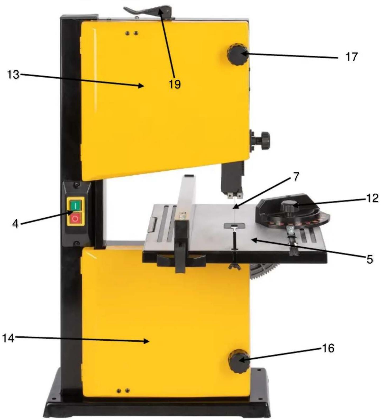
Fig. A

Fig. B

Fig. C
POWX1800
a
5
b
C
d
Fig. D


Fig. E
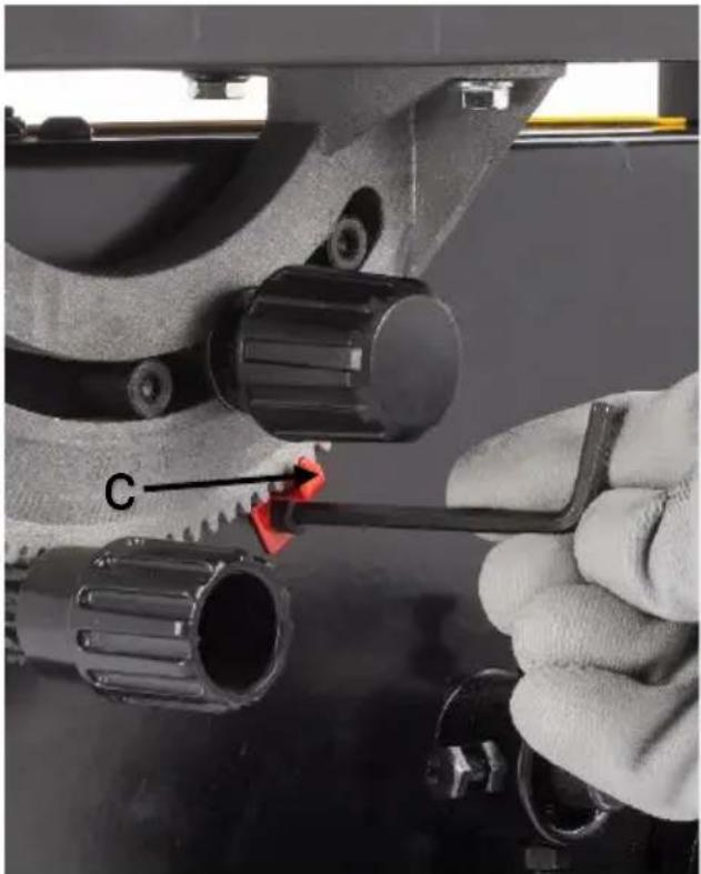
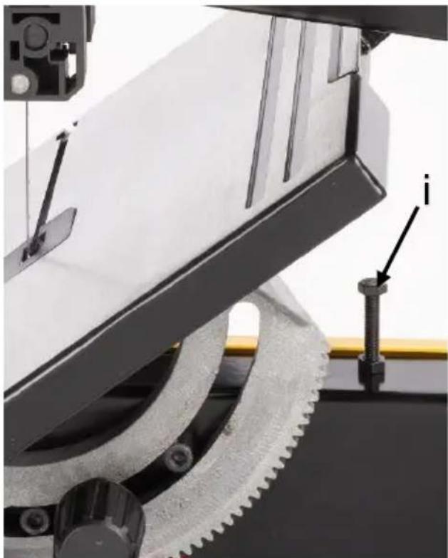
Fig. F


Fig. G


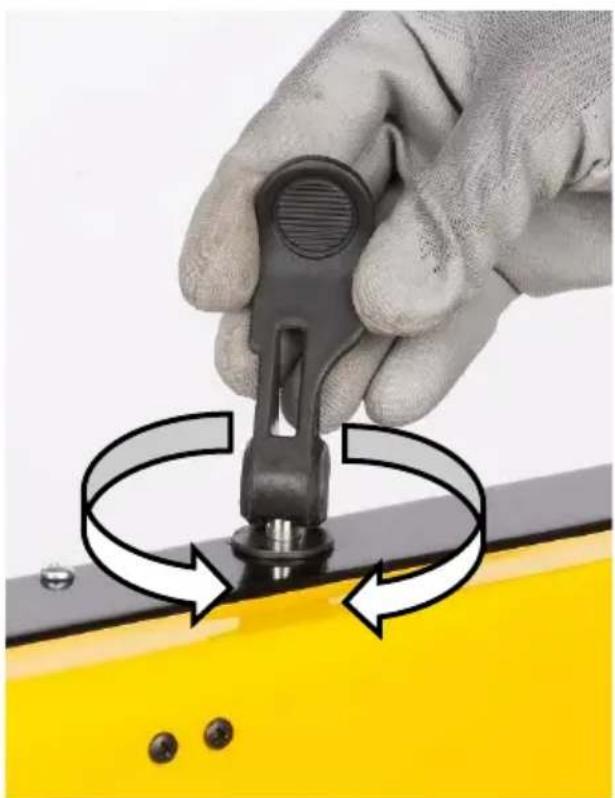

Fig. H


Fig.1


Fig. J
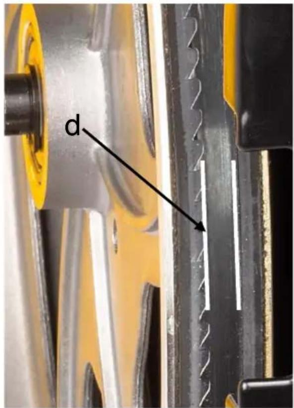

Fig. K
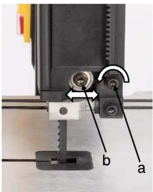

Fig. L
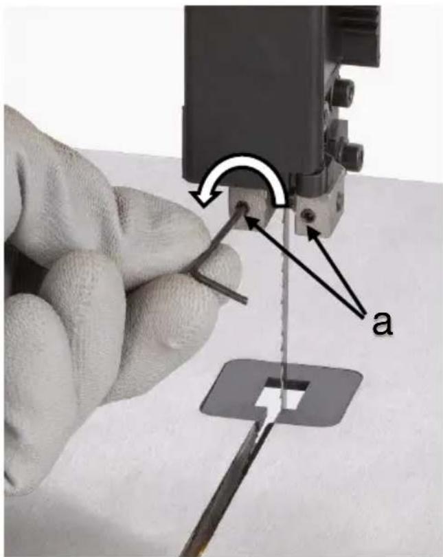


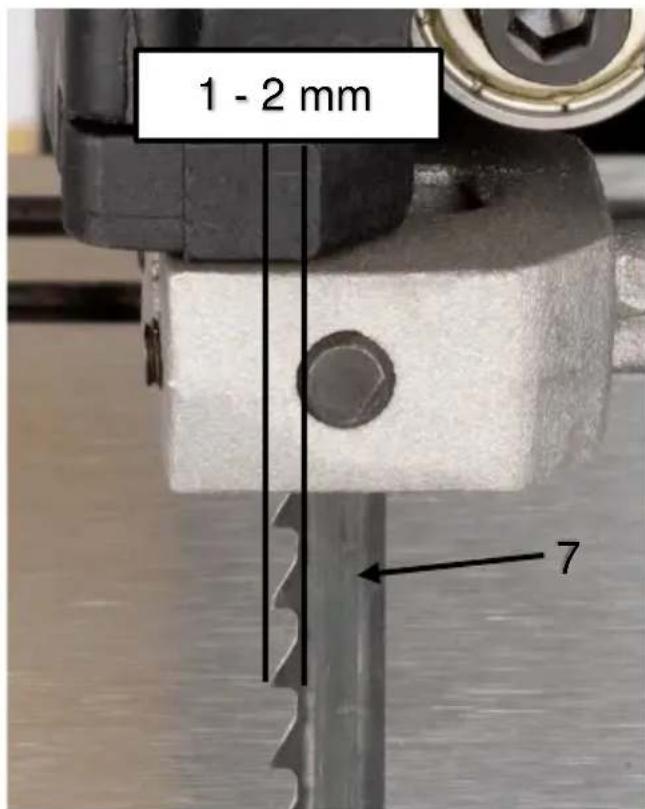
Fig. M


Fig. N


Fig. O
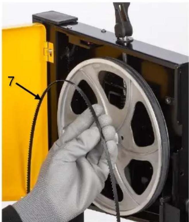

Fig. P


Fig. Q


Fig. R
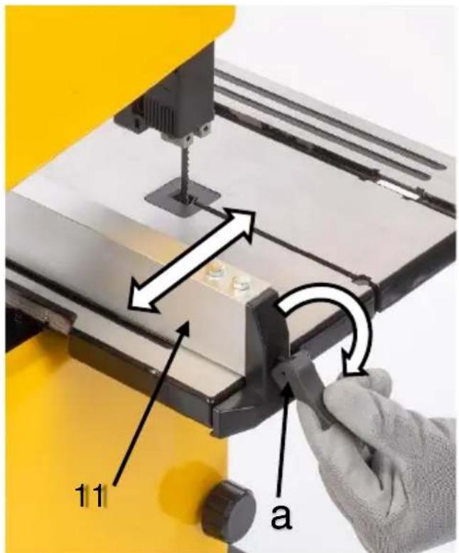

Fig. S


Fig. T
Fig. U


Fig. V
2006/42/EC Annex IV Notified Body
TuV Sud - DE
2014/30/EU
01/07/2022, Lier - Belgium
SCIE A RUBAN 350 W POWX1800
1 UTILISATION PRÉVUE
8 REMPLACEMENT DE PIECES (FIG. A, B, C, D ET P)
Annex IV Notified Body
TuV Sud - DE
11.1 Cleaning 11
11.2 Lubrication 11
12 TECHNICAL DATA 12
13 NOISE 12
14 SERVICE DEPARTMENT 12
15 STORAGE 12
16 WARRANTY 13
17 ENVIRONMENT 13
18 DECLARATION OF CONFORMITY 14
BANDSAW 350W POWX1800
1 INTENDED USE
This machine is designed for the longitudinal cut and lateral cutting of wood and similar materials. It is not designed for commercial use.

WARNING! Read this manual and general safety instructions carefully before using the appliance, for your own safety. Your power tool should only be passed on together with these instructions.
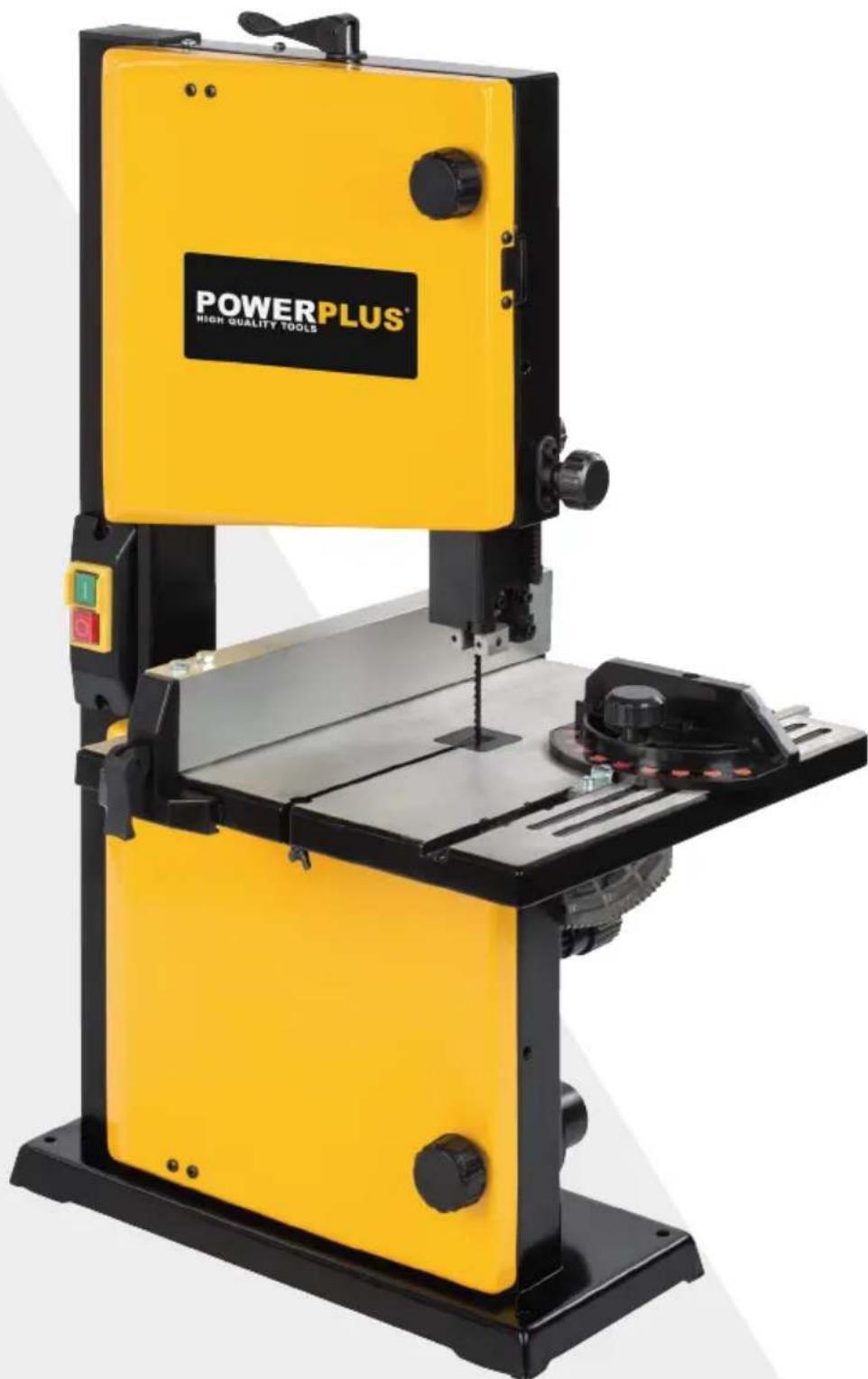
2 DESCRIPTION
- Machine base
- Dust extraction outlet
- Motor
- ON/OFF switch
- Work table
- Table angle scale
- Saw band
- Top saw band roller
- Bottom saw band roller
-
Table insert
-
Parallel guide
- Mitre gauge
- Top cover
- Bottom cover
- Saw band guard
- Saw band guide
- Cover lock knob
- Blade guard lock knob
- Blade tension lever
3 PACKAGE CONTENT LIST
- Remove all packing materials
- Remove remaining packaging and transit supports (if existing)
- Check the completeness of the packing content
- Check the appliance, the power cord, the power plug and all accessories for transportation damages.
- Keep the packaging materials as far as possible till the end of the warranty period.
Dispose it into your local waste disposal system afterwards.

WARNING Packing materials are no toys! Children must not play with plastic bags! Danger of suffocation!
1x bandsaw 350W
1x work table
1x parallel guide
1x miter gauge
1x table lock knob
1x washer (8mm)
2x hex key (2 + 4mm)
1x wrench (8*10mm)
1x push stick
1xM5x24
1x instruction manual

When parts are missing or damaged, please contact your dealer.
4 SYMBOLS
In this manual and/or on the machine the following symbols are used:
| Read manual before use | CE | In accordance with essential requirements of the European directive(s) |
| Warning / Danger | Wear eye protection | |
| Wear gloves | Wear noise protection | |
| Important information. | Electrical products must not be disposed with the domestic waste. |
5 GENERAL POWER TOOL SAFETY WARNINGS
- Read all safety warnings and all instructions. Failure to follow all warnings and instructions may result in electric shock, fire and/or serious injury. Save all warnings and instructions for future reference. The term "power tool" in the warnings refers to your mains operated (cored) power tool or battery operated (cordless) power tool.
5.1 Work area
-
Keep work area clean and well lit. Cluttered and dark areas invite accidents.
-
Do not operate power tools in explosive atmospheres, such as in the presence of flammable liquids, gases or dust. Power tools create sparks which may ignite the dust or fumes.
-
Keep children and bystanders away while operating a power tool. Distractions can cause you to lose control.
5.2 Electrical safety
- Power tool plugs must match the outlet. Never modify the plug in any way. Do not use any adapter plugs with earthed (grounded) power tools. Unmodified plugs and matching outlets will reduce risk of electric shock.
- Avoid body contact with earthed or grounded surfaces such as pipes, radiators, ranges and refrigerators. There is an increased risk of electric shock if your body is earthed or grounded.
- Do not expose power tools to rain or wet conditions. Water entering a power tool will increase the risk of electric shock.
- Do not abuse the cord. Never use the cord for carrying, pulling or unplugging the power tool. Keep cord away from heat, oil, sharp edges or moving parts. Damaged or entangled cords increase the risk of electric shock.
- When operating a power tool outdoors, use an extension cord suitable for outdoor use. Use of a cord suitable for outdoor use reduces the risk of electric shock.
- If operating a power tool in a damp location is unavoidable, use a residual current device (RCD) protected supply. Use of an RCD reduces the risk of electric shock.
- Always check that the power supply corresponds to the voltage on the rating plate.
5.3 Personal safety
- Stay alert, watch what you are doing and use common sense when operating a power tool. Do not use a power tool while you are tired or under the influence of drugs, alcohol or medication. A moment of inattention while operating power tools may result in serious personal injury.
- Use safety equipment. Always wear eye protection. Safety equipment such as dust mask, non-skid safety shoes, hard hat, or hearing protection used whenever conditions require will reduce personal injuries.
- Avoid accidental starting. Ensure the switch is in the off position before plugging in. Carrying power tools with your finger on the switch or plugging in power tools that have the switch on invites accidents.
- Remove any adjusting key or wrench before turning the power tool on. A wrench or a key left attached to a rotating part of the power tool may result in personal injury.
- Do not overreach. Keep proper footing and balance at all times. This enables better control of the power tool in unexpected situations.
- Dress properly. Do not wear loose clothing or jewellery. Keep your hair, clothing and gloves away from moving parts. Loose clothes, jewellery or long hair can be caught in moving parts.
If devices are provided for the connection of dust extraction and collection facilities, ensure these are connected and properly used. Use of these devices can reduce dust related hazards.
5.4 Power tool use and care
- Do not force the power tool. Use the correct power tool for your application. The correct power tool will do the job better and safer at the rate for which it was designed.
- Do not use the power tool if the switch does not turn it on and off. Any power tool that cannot be controlled with the switch is dangerous and must be repaired.
- Disconnect the plug from the power source before making any adjustments, changing accessories, or storing power tools. Such preventive safety measures reduce the risk of starting the power tool accidentally.
- Store idle power tools out of the reach of children and do not allow persons unfamiliar with the power tool or these instructions to operate the power tool. Power tools are dangerous in the hands of untrained users.
- Maintain power tools. Check for misalignment or sticking of moving parts, breakage of parts and any other condition that may affect the power tool's operation. If damaged, have the power tool repaired before use. Many accidents are caused by poorly maintained power tools.
- Keep cutting tools sharp and clean. Properly maintained cutting tools with sharp cutting edges are less likely to stick and are easier to control.
- Use the power tool, accessories and tool bits etc., in accordance with these instructions and in the manner intended for the particular type of power tool, taking into account the working conditions and the work to be performed. Use of the power tool for operations different from intended could lead to a hazardous situation.
5.5 Service
- Have your power tool serviced by a qualified repair person using only identical replacement parts. This will ensure that the safety of the power tool is maintained.
6 ASSEMBLY

Important. Pull the mains plug before starting any servicing, adjustment and assembly work.
6.1 Mounting the work table (Fig. D,E & F)
- Remove the M6x24 hex bolt (a), washer and wingnut from the work table assembly.
- Slide the work table (5) onto the band saw, making sure that the blade stays within the slot (b) in the table.
- Make sure the angle pointer (c) is loosened and pointing down so it doesn't interfere during the mounting procedure.
- Pull the angle adjustment knob (d) on the back of the band saw and align the teeth on the table tilt bracket (e) into the teeth on the angle adjustment knob. Release the knob (d).
- The table bracket slot (f) should fit over the 2 supporting studs (g).
- Assemble the flat washer and table lock knob (h) into the table bracket.
- Turn the table lock knob (h) to tighten the table assembly to the saw's frame.
NOTE: If the work table isn't perfectly level at the 0^ setting, use the table adjustment bolt (i) located under the work table to correct the table level.

You must remove the plate (j) (Fig. G) via loosening the two screws (k) with the screwdriver when tilting the work table up to 45 degree. If not, the frame (l) will interfere with the working table.
7 BAND SAW SETTINGS

Important : Always wear safety gloves when working on the saw band.

Attention! Before performing any work on the equipment, pull the power plug.

NOTE: The upper blade guard (15) (Fig. A & H) can be opened for easier access to the blade and bearing / side guides.
7.1 Tensioning the saw band (Fig. A,B,H & I)
- Important. If the machine is at a standstill for a lengthy period of time, the tension in the saw band (7) must be released.
- It is therefore important that you check the saw band tension before switching on the machine.
Loosen the saw band guard lock knob (18) (Fig. B) located on the back of the saw. - Raise the saw band guard (15) to the top by turning the blade guard adjustment knob (20) counter-clockwise.
- Lock the saw band guard (15) by turning the blade guard lock knob (18) (Fig. B) clockwise.
- Check the tension by tapping with a finger against the side of the blade halfway between the table and the upper guide.
- The blade should not flex more than 2mm .
- Lift up and turn the tension lever (19) clockwise to increase the blade tension or counter clockwise to decrease tension.
- Check and adjust the tension as necessary to make sure the blade is properly tensioned.
7.2 Saw band tracking (Fig. A,J & K)
Before initial cutting and after every blade change, check and adjust blade tracking so that the blade runs on the centre of the wheels.
- Turn off the band saw and unplug it from the power supply. Make sure that the blade is not moving, then open both the upper and lower wheel covers (13 & 14).
- Carefully rotate the upper wheel (8) manually for at least three rotations (making sure not to touch the blade) and watch the blade travel.
- If the blade is veering off to either side of the wheel, follow the next step to adjust blade tracking.
- Loosen the blade tracking lock knob (a). Continue to rotate the wheel and slowly turn the blade tracking knob (b) in the desired direction until the blade is centred over the wheels.
- Turning the blade tracking knob towards you shifts the blade to the left, and turning it away from you shifts the blade to the right.
- Spin the wheel a few more turns to ensure that the blade is now running consistently in the centre of the wheel (d).
- Close and lock the covers (13 & 14).

NOTE: The saw has a small window (e) that allows blade tracking inspection without needing to open the covers.
NOTE: Blade tracking will be more difficult with thinner blades.
7.3 Adjusting the saw band guides

Important : The support and guide bearings must be adjusted each time the saw band is changed.
7.3.1 Upper Thrust Bearing (Fig. L):
- Loosen the upper right bolt (a) using the S4 hex wrench to adjust the position of the thrust bearing (b) running along the back of the saw band.
- The bearing should be positioned 0.5mm from the back of the saw band.
- Retighten the bolt (a).
7.3.2 Upper Side Guides (Fig.M):
- Loosen the two grub screws (a) using the S2 hex wrench to adjust the two side guides at either side of the blade.
- The side guides (b) should be positioned 0.25 mm away from the saw band (7).
- Retighten the grub screws (a).
- Loosen the lower right bolt (c) using the S4 hex wrench.
- Move the guide block (d) to position the side guides 1 to 2mm from the teeth of the blade (7).
- Retighten the bolt (c).
7.3.3 Lower blade bearing and side guides adjustment (Fig.A & N).
- Open the lower wheel cover (14).
- The table might need to be removed for easier access to the adjustment screws.
- The procedure is the same as adjusting the upper bearing and guides.
- Proceed in the same way as explained in paragraph 7.3.1 and 7.3.2, the bearing and side guides are exactly the same.
The locking bolt "a" in figure L and the locking bolt "c" in figure M however need to be accessed differently via 2 holes (b) in the saw chassis directly under the work table. - Close the lower wheel cover.
7.3.4 Adjusting the work table angle. (Fig. B & O)
Loosen the table lock knob (a) located on the back of the band saw.
- Adjust the table to the desired angle using the angle adjustment knob (b) and the angle indicator (c).
The table can be tilted 45 degrees.
- Use the angle indicator (c) and table angle scale (6) to confirm the desired angle and tighten the table lock knob (a).

NOTE: The table perpendicular to the blade corresponds to a scale indication of 0^ .
8 PARTS REPLACEMENT (FIG. A,B,C,D & P)
8.1 Change the saw band

Important : Always wear safety gloves when working on the saw band
- Remove the M6x24 hex bolt, spring washer, flat washer and wing nut (a) (Fig. D) from the work table assembly.
- Open the upper and lower blade covers (13 & 14). Set the upper blade guard (15) to its lowest position, minimizing the space between the bottom of the blade guard and the work table.
- Open the blade guard cover (15) by pinching the ridged surface on the bottom left of the cover and pulling it outwards (Fig. H).
- Lift up and loosen the tension knob (19) until you can remove the saw band from the machine (Fig. P).
NOTE: Now is a good time to clean out your band saw to ensure the best performance. - Clear out any sawdust, wood chips, etc. with a shop vacuum.
- Ensure that the wheels and rubber bands are free of sawdust and chips.
- This promotes good wheel balance and good blade tracking.
- Fit the new saw band through the guiding slots on both the left and right sides of the machine onto the upper and lower rubber bands.
- Position the saw band in the centre of the rubber bands.
- Ensure that the blade teeth are pointing down towards the table.
- Turn the blade tensioning knob (19) clockwise to put the new saw band under tension.
- Close the upper blade guide cover (15) by pushing in until it clicks in place.
- Replace the M6x24 hex bolt, spring washer, flat washer and wing nut (a) (Fig. D) onto the work table assembly.
- After every blade change, make sure to follow the instructions in chapter 7 to adjust the tracking of the saw band, the tension, and the upper and lower saw band guides.
- Proper tuning of your band saw is necessary to ensure optimum performance of the machine.
- After all adjustments and tuning are complete, close and lock the upper and lower wheel covers (13& 14).
8.2 Criteria for selecting the correct saw band.
- Narrow saw bands: Suitable for cutting tight radii.
- Wide saw bands: Suitable for long straight cuts in wood. Narrow saw bands have a tendency to follow the grain in the wood.
- Saw band teeth: Fine teeth produce a fine, but slow cut.
- Coarse teeth produce a coarse, but fast cut.
- The saw band supplied with the machine is a universal saw band.
8.3 Replace the rubber treads on the saw band rollers (Fig. A,C & P)
- First remove the saw band (7) as described in paragraph 8.1.
- Raise the rubber tread (a) on the top saw band roller (8) using a small screwdriver and pull it off the saw band roller.
- Proceed in the same way on the bottom saw band roller (9).
Pull the new rubber treads (a) on to the saw band rollers (8 & 9). - Ft the saw band (7) again as described in paragraph 8.1 and close the side covers (13 & 14).
8.4 Replace the bench insert (Fig. C & Q)
- The bench insert (a) must be replaced if it suffers wear or damage since otherwise it will pose a great risk of injury.
- Press the old bench insert (a) out of the saw bench (5) from underneath.
- Fit the new bench insert (a) into the saw bench (5) from above.
9 BEFORE OPERATION (FIG. A & C)
- Please note that the tool must be placed in a stable position on a workbench or bolted to a solid sub-frame.
- There are holes in the machine foot (1) for securing it.
- Before starting the machine, check that all covers and safety equipment are correctly fitted.
- Ensure that the saw band (7) moves freely.
- Before you switch on the tool, ensure that all the moving parts move easily and that the saw band is installed correctly.
- Before connecting the tool to the power supply, ensure that the data on the rating plate are identical to the mains data.
- Check the workpiece you intend to cut for foreign bodies such as nails or screws and remove them if necessary.
10 OPERATION

Read the following operation safety procedures to avoid personal injury and or damage to the device and or workpiece.
- When working with the bandsaw always move the top saw band guide (16) as close as possible to the workpiece.
- Press the workpiece as flat as possible on to the saw bench (5) to prevent the saw band (7) from jamming.
- Guide the workpiece at a uniform feed speed so that the saw band (7) can cut through the material easily and without jamming.
- Use the parallel stop (11) or lateral stop (12) for all cuts on which they can be used.
Always guide your workpiece from the longest side whilst sawing it.
Always complete cuts in one operation wherever possible. - If you have no choice but to pull back a workpiece, you must first switch off the bandsaw and wait for the saw band (7) to reach a standstill.
10.1 Dust extraction (Fig. B & Q)
For a better dust extraction of the working surface, your machine can be connected to the ordinary vacuum cleaner for house-use.
10.2 Switch on/off (Fig. A)
- Start the bandsaw by pressing the green "I" button (4).
- Stop the bandsaw by pressing the red "0" button (4).
Important. The bandsaw is fitted with a safety switch to prevent its restarting after a power failure.
10.3 Using the Mitre gauge (Fig. A & R)
- Slide the metre gauge (12) into one of the two grooves on the work table (5)
- Undo the securing screw (a) on the mitre gauge
- Set the required angle on the scale.
- Tighten the securing screw (a) again.
10.4 Using the parallel guide (Fig. B & S)
- The parallel guide (11) is used for making straight cuts.
Position the parallel guide (11) onto the work table with the side parallel to the blade. - Adjust the distance of the parallel guide (11) to the blade depending on the length you would like to cut.
- Lock it in place by pushing down on the fence lock handle (a).
- Make sure the fence is locked down before operation.
10.5 Making angled cuts (Fig. A,B & T)
- The saw bench (5) can be angled from 0^ to 45^ to the outside for making angled cuts.
See paragraph 7.3.4 on how to adjust the work table angle.

Important : To secure workpieces whose size allows it, to prevent them from sliding away, the parallel guide (11) must always be fitted on the outside right of the saw bench (5) for making angled cuts.
If the workpiece size allows it, fit the parallel guide (11) on the outside right of the saw bench (5).
- Lower the saw band guide (16) as far as possible on to the workpiece.
- Switch on the bandsaw.
- Press the workpiece against the parallel guide (11) with your left hand.
- Press the workpiece flat on to the saw bench (5) with your other hand.
- Now Slide the workpiece against the saw band (7) at a uniform feed speed.

Important : After you have completed all the adjustments, it is advisable to carry out a test cut to ensure that all the dimensions you have set are correct.
10.6 Making longitudinal cuts (Fig. A,B & U)
Cut a workpiece longitudinally.
- If possible fit the parallel guide (11) to the lefthand side of the saw bench (5).
- Lower the saw band guide (16) as far as possible on to the workpiece.
- Switch on the bandsaw.
- Press the workpiece against the parallel stop (11) with your right hand.
- Press the workpiece flat on to the saw bench (5) with your other hand.
- Now Slide the workpiece against the saw band (7) at a uniform feed speed.
10.7 Making cross cuts (Fig. A,B,R & S)
Cut a workpiece laterally.
- Push the metre gauge (12) into one of the two grooves on the work table (5) and set the required angle on the scale on the metre gauge (12)
- Lower the saw band guide (16) as far as possible on to the workpiece.
- Switch on the bandsaw.
- Press the workpiece firmly against the litre gauge (12) with your right hand.
- Press the workpiece flat on to the work table (5) with your other hand.
- Now Slide the workpiece against the saw band (7) at a uniform feed speed.
10.8 Making double litre cuts (Fig. R & V)
- Cut a workpiece laterally.
- Push the metre gauge (12) into one of the two grooves on the work table (5) and set the required angle on the scale on the metre gauge (12)
- Lower the saw band guide (16) as far as possible on to the workpiece.
- Switch on the bandsaw.
- Press the workpiece firmly against the metre gauge (12) with your right hand.
- Press the workpiece flat on to the work table (5) with your other hand.
- Now Slide the workpiece against the saw band (7) at a uniform feed speed.
10.9 Making free-hand cuts (Fig.V)
The most outstanding feature of a bandsaw is its facility that enables you to complete freehand cuts.
- Lower the saw band guide (16) as far as possible on to the workpiece.
- Switch on the bandsaw.
Press the workpiece flat on the saw bench (5) and slide it slowly up to the saw band (7).
Use a low feed speed for all free-Hand cuts since this will enable you to follow the required line more easily.
in some cases you may have to make a coarse cut approximately 5 - 10 mm away from the actual cutting line.
If the curve you wish to cut is too tight for the saw band (7) you are using, you must first make auxiliary cuts up to the front edge of the curve so that these pieces of wood will fall away when you have sawn the final radius.
11 MAINTENANCE AND CARE

Attention! Before performing any work on the equipment, pull the power plug.
11.1 Cleaning
- Keep the ventilation slots of the machine clean to prevent overheating of the engine.
- Regularly clean the machine housing with a soft cloth, preferably after each use.
- Keep the ventilation slots free from dust and dirt.
- If the dirt does not come off use a soft cloth moistened with soapy water.

Never use solvents such as petrol, alcohol, ammonia water, etc. These solvents may damage the plastic parts.
11.2 Lubrication
Oil the saw band guides (19) (20) (21) (top and bottom) at regular intervals.
12 TECHNICAL DATA
| Mains voltage | 230-240 V~ |
| Mains frequency: | 50 Hz |
| Rating: | 350 W (S2: 10min) |
| Motor type | induction |
| Saw band speed | 630 m / min |
| Blade length: | 1511 mm |
| Blade width: | 6,5 mm |
| Max. Cutting depth: | 89 mm |
| Max. Cutting width: | 228 mm |
| Bench size: | 313 x 302 mm |
| Mitre: | 0°-45° |
| Weight: | 19 kg |
| Dust outlet diameter | 63,5 mm |
13 NOISE
| Noise emission values measured according to relevant standard. (K=3) | |
| Acoustic pressure level LpA | 91 dB(A) |
| Acoustic power level LwA | 99 dB(A) |

ATTENTION! Wear hearing protection when sound pressure is over 85 dB(A).
14 SERVICE DEPARTMENT
Damaged switches must be replaced by our after-sales service department.
- If the connecting cable (or mains plug) is damaged, it must be replaced by a particular connecting cable which is available from our service department. Replacement of the connecting cable must only be carried out by our service department (see last page) or by a qualified person (qualified electrician).
15 STORAGE
- Thoroughly clean the whole machine and its accessories.
- Store it out of the reach of children, in a stable and secure position, in a cool and dry place, avoid too high and too low temperatures.
16 WARRANTY
This product is warranted for a 36-month period effective from the date of purchase by the first user.
- This warranty covers all material or production flaws excluding : batteries, chargers, defective parts subject to normal wear & tear such as bearings, brushes, cables, and plugs, or accessories such as drills, drill bits, saw blades, etc. ; damage or defects resulting from maltreatment, accidents or alterations; nor the cost of transportation.
- Damage and/or defects resulting from inappropriate use also do not fall under the warranty provisions.
We also disclaim all liability for any bodily injury resulting from inappropriate use of the tool.
- Repairs may only be carried out by an authorised customer service centre for Powerplus tools.
- You can always obtain more information at the number 00 32 3 292 92 90.
- Any transportation costs shall always be borne by the customer, unless agreed otherwise in writing.
- At the same time, no claim can be made on the warranty if the damage of the device is the result of negligent maintenance or overload.
- Definitely excluded from the warranty is damage resulting from fluid permeation, excessive dust penetration, intentional damage (on purpose or by gross carelessness), inappropriate usage (use for purposes for which the device is not suitable), incompetent usage (e.g. not following the instructions given in the manual), inexpert assembly, lightning strike, erroneous net voltage. This list is not exhaustive.
- Acceptance of claims under warranty can never lead to the prolongation of the warranty period nor commencement of a new warranty period in case of a device replacement.
Devices or parts which are replaced under the warranty therefore remain the property of Varo NV.
- We reserve the right to reject a claim whenever the purchase cannot be verified or when it is clear that the product has not been properly maintained. (Clean ventilation slots, carbon brushes serviced regularly, etc.).
- Your purchase receipt must be kept as proof of date of purchase.
- Your appliance must be returned undismantled to your dealer in an acceptably clean state, (in its original blow-moulded case if applicable to the unit), accompanied by proof of purchase.
17 ENVIRONMENT

Should your appliance need replacement after extended use, do not discard it with the household refuse but dispose of it in an environmentally safe way. Waste produced by electrical machine items should not be handled like normal household rubbish. Please recycle where recycle facilities exist. Check with your Local Authority or retailer for recycling advice.
VARO N.V. - Vic. Van Rompuy N.V. Joseph Van Instraat 9 - BE2500 Lier - BELGIUM, declares that,
product : Bandsaw 350W
trade mark : POWERplus
model:POWX1800
is in conformity with the essential requirements and other relevant provisions of the applicable European Directives, based on the application of European harmonized standards. Any unauthorized modification of the apparatus voids this declaration.
European Directives (including, if applicable, their amendments up to the date of signature);
2011/65/EU
2006/42/EC Annex IV Notified Body TuV Sud - DE
2014/30/EU
European harmonized standards (including, if applicable, their amendments up to the date of signature);
EN61029-1:2009
EN61029-2-5:2011
ENIEC55014-1:2021
EN IEC55014-2:2021
EN IEC 61000-3-2:2019
EN61000-3-3:2013
Keeper of the Technical Documentation : Philippe Vankerkhove, VARO - Vic. Van Rompuy N.V.
The undersigned acts on behalf of the company CEO,
Mertens Ludo
Ludo Mertens
Regulatory Affairs - Compliance Manager
01/07/2022, Lier - Belgium
2006/42/EC Annex IV Notified Body
TuV Sud - DE
2014/30/EU
01/07/2022, Lier - Belgium
Annex IV Notified Body
TuV Sud - DE
01/07/2022, Lier - Belgium
2006/42/EC Annex IV Notified Body
TuV Sud - DE
2014/30/EU
Regulatory Affairs - Compliance Manager
01/07/2022, Lier - Belgium
1 UTILIZACAO PREVISTA 3
2 DESCRIÇÃO 3
3 LISTA DE CONTEUDO DA EMBALAGEM 3
4 SIMBOLOS 4
5 PROCEDIMENTOS GERAIS DE SEGURANCA 4
5.1 Local de trabajo 4
5.2 Seguranca eltrica 4
5.3 Segurancia de pessoas 5
5.4 Manuseamento e emprego de ferramentas elétricas com precação 5
5.5 Assistance Tecnica 6
6 MONTAGEM 6
6.1 Montar a mesa de trabajo (Fig. D, E e F) 6
7 CONFIGURAÇões DA SERRA DE FITA 6
7.1 Tensionar a fita da serra (Fig. A, B, H e I). 6
7.2 Trilho da fita de serra (Fig. A, Je K) 7
7.3 Ajustar as guia da fita da serra 7
7.3.1 Rolamento de impulso superior (Fig. L). 7
7.3.2 Guias laterais superiores (Fig.M) 7
7.3.3 Ajuste do rolamento da lamina inferior e das guias laterais (Fig. A e N). 8
7.3.4 Ajuste o angulo da mesa de trabajo. (Fig. B e O) 8
8 SUBSTITUÇÃO DE PEÇAS (FIG. A, B, C, D E P) 8
8.1 Substituir a fita da serra 8
8.2 Critério para seleccionar a fita de serra correta. 9
8.3 Substitua as bandas de rodagem de borracha nos rolos da fita da serra (Fig. A, C e P). 9
8.4 Substitua a inscrcao da bancada (Fig. C e Q) 9
9 ANTES DA PRIMEIRA UTILIZACAO DA FERRAMENTA (FIG. A & C) 9
10 OPERACAO 10
10.1 Recolha das poeiras (Fig. B & Q) 10
10.2 Interruptor on/off (Fig. A). 10
POWERPLUS HIGH QUALITY TOOLS
POWX1800 PT
10.3 Usar um medidor de esquadria (Fig. A e R) 10
10.4 Usar o guia paralelo (Fig. B e S). 10
10.5 Realizar cortes angulares (Fig. A, B e T) 10
10.6 Fazer cortes longitudinalis (Fig. A, B e U) 11
10.7 Realizar cortes transversais (Fig. A, B, Re S) 11
10.8 Realizar cortes angulares duplos (Fig. Re V) 11
10.9 Fazer cortes livres (Fig. V) 11
10.2 Interruptor on/off (Fig. A)
2006/42/EC Annex IV Notified Body
TuV Sud - DE
2014/30/EU
01/07/2022, Lier - Belgium
BANDSAG 350 WPOWX1800
1 TILTENKT BRUK
8 UTSKIFTING AV DELER (FIG. A, B, C, D OG P)
8.1 Skifte sagblad

Viktig: Bruk alltid beskyttelseshansker nár du arbeider med sagbladet.
11 VEDLIKEHOLD OG STELL

01/07/2022, Lier - Belgium
8 UDSKIFTNING AF DELE (FIG. A, B, C, D & P)
BANDSAG 350 W POWX1800
1 AVSEDD ANVÄNDNING
8 BYTE AV DELAR (FIG. A, B, C, D & P)
8.1 Byte av sagbandet

Annex IV Notified Body
TuV Sud - DE
Europeiska harmoniserade standarder (inklusive, i tillampliga fall, andringar till dessa, fram till dagen for undertecknandet):
EN61029-1:2009
EN61029-2-5:2011
EN IEC55014-1:2021
EN IEC55014-2:2021
EN IEC 61000-3-2:2019
EN61000-3-3:2013
Anvariig for den tekiska dokumentationen: Philippe Vankerkhove, VARO - Vic. Van Rompuy N.V.
01/07/2022, Lier - Belgium
01/07/2022, Lier - Belgium
1 IPOBAEIOMENH XPHSH 3
2 KATAAOTO EAPTHMATQN 3
3 AIZTA NEPIEXOMENON YZKEYAIAI 3
4 SYMBOAA 4
5 TENIKEZ SYMBOYAEI A THN AΦAΛEIA 4
5.1 Xwpoc epyaia
5.2 HLeKtpiKn aOaia 4
5.3 Atoiikn aovapaleia 5
5.4 PooektikocxepiooKai xponTuw nEeptipkow epyaieiw 5
5.5 6
6 SYNAPMOAOH2H 6
6.1 Σuvapuoloyon rou rpaneziou εpyoiaε (Eik. D, E kai F) 6
7 PYOMIeI TAINIOPIONOY
7.1 Tavoun ng nC npiovoraiaic (Eik.A,B,X & I) 7
7.2 ApoioIoynon npiovoraia (Eik.A,J&K) 7
7.3 PuOiOg Twv oBnyW npiovotaiaC 8
7.3.1 Avw wotikó pouεμáv (Eik. L). 8
7.3.2 Eπavw πεuipikoi odnyoi (Eik.M) 8
7.3.3 Puθμion katw pouεμáv λεπίας kal πλευρικων onγών (Eik.A & N) 8
7.3.4 Puroion nC ywiaou patieioe pyaoiae (Eik.B & O) 8
8 ANTIKATAZAHTMHMATQN (EIK.A,B,C,D & P) 9
8.1 Alambda npiovoiaic 9
8.2 Kpirtipia yia tnv eiloyin ts osotnc npiovotaiia
8.3 AvriKaTaOaTOn TwV ELaOToIKW V TeMaTuWv OToUs KUAlivOpouc Tns Ppiovotaiviae (Eik.A,C &P) 10
8.4 Avikataaon rou evetou mayou (Eik.C & Q) 10
9 PPIN XPHSIMONIOIHSETE TO EPIAIEIO IIA IPQTH OFOPA..10
10 AEITOYPTIA 10
10.1 u o k o (E i ,B\& Q) 11
10.2 Avapma/Σβnσiμo (Eik. A) 11
10.3 Xpno rou mepnnt qaltooywviae (Eik.A & R) 11
POWERPLUS HIGH QUALITY TOOLS
POWX1800 EL
10.4 Xpion rou napalnnou oynou (Eik.B & S) 11
10.5 EkTeAeon ywiaKwV KOnWv (Eik.A,B & T) 11
10.6 paaypaTOnoInon rouov kata pkoC (Eik.A,B & U) 12
10.7 Ppaaypaonoinon ykapoiw konov (Eik.A,B,R & S) 12
10.8 EkTeAeon dInawv aalrookonwv (Eik.R & V) 12
10.9 paaypaonoinoEeueθepwv touWv (Eik.V) 12
11 SYNTHPHESH KAI IPOEIA 13
11.1 Kaθαρισμός 13
11.2 Aitavon 13
12 TEXNIKA XAPAKTHPIETIKA 13
13 0OPYBOE 13
14 TMHMA ΣEPBIS 14
15 ANOOHKEYsH 14
16 ERTYH
17 IEPIBAON 15
18 △HAΩEH ΣYMMOPΦΩEH
1 PPOBÄENOMENH XPHΣH
AutoTo mnxavma eivai oxediaouevo yia kottn kat a nkoC kai TLEupikn KOTn Eluou kai TAPooiuv uikov. Akatalnnlo yia ETayveaatikn xpon.

NPOEIAONIOIH! NapakaIoue diaaote TPOOeKTKa To EYXeiipio Xpnons TPIV aTTO xPnON KAI quAeTe TO YIA VA AVATpeXeTe Oe auto oTo MAAov. EAV mTaBiaoe auto To nAeKtpiKO epyaleio, TAPadwote paCi kai Tc odnyiecs XpnoNS.
2 KATAANO EAPTHMATQN
9 IPIN XPHESIMONIOIHSETE TO EPRAAEIO FIA INPQTH OFOPA
11 SYNTHPHESH KAI IPOSTAIA

Ppoooxn! Ppiv EkTeLeoTe OToiabntote Epyaia oTo epyaieio, Byalte to aTTOV piz.
11.1 Kaθαρισμός
Annex IV Notified Body
TuV Sud - DE
Eupwtaiká evapovioéva πótuα (ouπελαβavovtac, kaT πepiTTwaŋ, Tc TpOITOTIOIeIc Touc eωs TnV ηερoynvia UToypαφns):
EN61029-1:2009
EN61029-2-5:2011
EN IEC55014-1:2021
EN IEC55014-2:2021
EN IEC 61000-3-2:2019
EN61000-3-3:2013
01/07/2022, Lier - Belgium
1 NAMJENA 3
2 OPIS (SLIKA) 3
3 POPISSADRZAJAPAKIRANJA 3
4 SIMBOLI 4
5 OPCA UPOZORENJA O ELEKTRICNIM ALATIMA 4
5.1 Područje za rad 4
5.2 Elektricna sigurnost 4
5.3 Osobna sigurnost 5
5.4 Koristenje i odrzavanje elektricnog alata 5
5.5 Servis 6
6 SASTAVLJANJE. 6
6.1 Postavljanje radnog stola (slike D, E i F) 6
7 POSTAVKE TRACNE PILE 6
7.1 Zatezanje rezne trake (slike A, B, H i I) 6
7.2 Putanja kretanja rezne trake (slike A, Ji K)
7.3 Podesavanje vodilica rezne trake 7
7.3.1 Gornji potisni lezaj (sika L) 7
7.3.2 Gornje bočne vodilice (slika M) 7
7.3.3 Podešavanje donjeg ležaja rezne trake i bočnih vodilica (slike A i N) 7
7.3.4 Podesavanje kuta radnog stola (slike B i O) 8
8 ZAMJENA DIJELOVA (SLIKE A, B, C, DIP) 8
8.1 Promjena rezne trake 8
8.2 Kriteriji za odabir ispravne rezne trake.. 9
8.3 Zamijenite gumene gazista na valjcima rezne trake (slike A, C i P) 9
8.4 Zamijenite umetak stola (slike C i Q) 9
9 PRIJE PRVE UPOTREBE ALATA (SLIKE A I C) 9
10 UPOTREBA 9
10.1 Usisivanje prase (slike Bi Q) 10
10.2 Ukljucivanje / iskljucivanje (slika A) 10
10.3 Koristenje kutomjera za koso izrezivanje (slike A i R) 10
10.4 Podesavanje parallelnvodilice (slike B i S) 10
10.5 Izrada rezova pod kutom (slike A, B i T) 10
10.6 Izvodenje poprechnih rezova (slike A, B i U) 10
10.7 Poprečni rezovi (slike A, B, Ri S) 11
10.8 Izvodenje dvostrukih kosih rezova (slike R i V) 11
10.9 Izrada prostoručnih rezova (slika V) 11
11 CIsCENJE I ODRZAVANJE 11
11.1 Cijscenje 11
11.2 Podmazivanje 11
12 TEHNICKI PODACI 12
13 BUKA 12
14 SERVISNI ODJEL 12
15 CUVANJE 12
16 JAMSTVO 13
17 OKOLIŠ 13
18 IZJAVA O SUKLADNOSTI 14
TRAÇNA PILA 350 W POWX1800
1 NAMJENA
01/07/2022, Lier - Belgium
1 NAMEJENA UPOTREBA 3
2 OPIS 3
3 LISTASADRZAJAPAKETA 3
4 SIMBOLI 4
5 OPŠTA BEZBEDNOSNA UPUTSTVA ZA ELEKTRICNE ALATE.4
5.1 Radna oblast 4
5.2 Elektricna bezbednost 4
5.3 Lična bezbednost. 5
5.4 Korisćenje i odžavanje elektrichnog alata 5
5.5 Servisiranje 6
6 SKLAPANJE 6
6.1 Montiranje radne ploce (SI. D, E i F) 6
7 POSTAVKE TRAKASTE TESTERE 6
7.1 Zatezanje trakastog lista (SI.A,B,Hil) 6
7.2 Centriranje trakastog lista (Sl. A, J i K) 7
7.3 Podesavanje vodica trakastog lista 7
7.3.1 Gornje aktijalno leziiste (SI. L) 7
7.3.2 Gornje bočne vodice (SI. M) 7
7.3.3 Podešavanje donjeg ležista lista i bočnih vodica (SI. A i N) 8
7.3.4 Podešavanje uglaradne ploce (Sl. Bi O) 8
8 ZAMENA DELOVA (SL. A, B, C, D & P) 8
8.1 Zamena trakastog lista 8
8.2 Kriterijumi za izbor odgovarajućeg trakastog lista testere...9
8.3 Zamena gumenih traka na valjcima trakastog lista (Sl. A, C i P). 9
8.4 Zamena umetka ploche (SI.CiQ) 9
9 PRE PRVE UPOTREBE OVOG ALATA (SL. A & C) 9
10 RUKOVANJE 9
10.1 Uklanjanje prase (SI.B & Q) 10
10.2 Ukljucivanje/isključivanje (SI. A) 10
10.3 Upotreba merača kosog ugl (Sl. A i R) 10
10.4 Upotreba paralelnog graničnika (SI. B i S) 10
10.5 Sechenje pod uglom (SI. A, B i T) 10
10.6 Poduzno secenje (Sl. A, B & U) 10
10.7 Izvodenje poprechnih rezova (SI.A,B,Ri S) 11
10.8 Izvodenje dvostrukih kosih rezova (Sl.RiV) 11
10.9 Slobodoručno sečenje (SI. V) 11
11 CIsCENJE I ODRZAVANJE 11
11.1 Cijscenje 11
11.2 Podmazivanje 12
12 TEHNIcKi PODACl 12
13 BUKA 12
14 SERVISNO ODELJENJE 12
15 SKLADIStENJE 12
16 GARANCIJA 13
17 ZIVOTNA SREDINA 13
18 IZJAVA O USKLADENOSTI 14
TRAKASTA TESTERA 350 W POWX1800
1 NAMENJENA UPOTREBA
Ova mašina je dizajnirana za podužno sečenje i poprečno sečenje drveta i sličnih materijala. Nije pogodno za profesionalnu upotrebu.

01/07/2022, Lier - Belgium
1 URcENePOUzITI 3
2 POPIS 3
3 OBSAH BALENI 3
4 SYMBOLY 4
5 OBECNÁ BEZPEČNOSTNI UPOZORNÉNÍ PRO ELEKTRICKÉ STROJE. 4
5.1 Pracovni oblast 4
5.2 Elektrická bezpečnost 4
5.3 Osobni bezpečnost 5
5.4 Použivanié elektrickych stroju a pece o ně 5
5.5 Servis 6
6 MONTAZ 6
6.1 Montaz pracovniho stolu (obrazky D, E a F) 6
7 NASTAVENI PÁSOVÉ PILY 6
7.1 Naputif piloveho pasu (obrazky A, B, H, I) 6
7.2 Stopa piloveho pasu (obrazky A, J, K) 7
7.3 Nastaveni vedeni pilového pásu 7
7.3.1 Horni tlačné ložisko (obrázek L) 7
7.3.2 Horni bočni vedení (obrázek M) 7
7.3.3 Nastaveni spodniho loziska pasu a bochich vedeni (obrazky A, N) 7
7.3.4 Nastaveni uhlu pracovniho stolu (obrazky B, O). 8
8 VYMENA DILU (OBRAZKY A, B, C, D, P) 8
8.1 Vymena piloveho pasu 8
8.2 Kriteria vybreu spravneho piloveho pasu 8
8.3 Vymena gumovych bēhounu na kladkach piloveho pásu (obrázky A, C, P) .......8
8.4 Vymena vložky stolu (obrázky C, Q) 9
9 PRED PRVNIM POUZITIM STROJE (OBRAZKY A, C) 9
10 PROVOZ 9
10.1 Odsavani prachu (obrazky B, Q) 9
10.2 Zapinani a vypinani (obrazek A) 9
10.3 Pouziti stupnice sikmeho rezu (obrazky A, R) 10
POWERPLUS HIGH QUALITY TOOLS
POWX1800 CS
PÁSOVÁ PILA 350 W POWX1800
1 URČENÉ POUžITÍ
Tento stroj je urcen k podelnému a pričnému rezání dřeva a podobnych materialú. Neni vchodné k profesonánlínu použití.

01/07/2022, Lier - Belgium
1 ZAMYSLANEPOUZITIE 3
2 POPIS 3
3 OBSAH BALENIA 3
4 VYSVETLENIE SYMBOLOV 4
5 VŠEOBECNÉ BEZPECNOSTNÉ VAROVANIA PRE ELEKTRICKÉ NÁRADIE. 4
5.1 Pracovná plocha 4
5.2 Elektrická bezpečnost' 4
5.3 Osobná bezpečnost 5
5.4 Použivanie elektrického náradia a starostlivost' on... 5
5.5 Servis 6
6 MONTAZ. 6
6.1 Montáž pracovného stola (obr. D, E a F) 6
7 NASTAVENIA PÁSOVEJ PÍLY 6
7.1 Napinanie piloveho pasu (obr. A, B, H a l) 6
7.2 Draha piloveho pasu (obr. A, J a K) 7
7.3 Uprava vodiacich prvkov piloveho pasu 7
7.3.1 Horné axiáne ložisko (obr. L). 7
7.3.2 Horné bočné vodiace privky (obr. M) 7
7.3.3 Nastavenie spodného ložiska listu a nastavenie bočných vodiacich prvkov (obr. A a N). 8
7.3.4 Nastavenie uhla pracovneho stola (obr. B a O) 8
8 VYMENA DIELOV (OBR. A, B, C, D A P) 8
8.1 Vymena piloveho pasu 8
8.2 Kriteria vyberu spravneho piloveho pasu 9
8.3 Vymene gumené behune na valcekoch piloveho pasu (obr. A, C a P) 9
8.4 Vymene vlozku pracovnej lavice (obr. C a Q) 9
9 PRED PRVYMPOUZITIM NASTROJA (OBR.A A C) 9
10 PREVÁDZKA 9
10.1 Vysavanie prachu (obr. B a Q) 10
10.2 Hlavny vypinač (obr. A) 10
POWERPLUS HIGH QUALITY TOOLS
POWX1800 SK
10.3 Použivanie uhlového pravitka (obr. A a R) 10
10.4 Použivanie paralelného vodiaceho prvku (obr. B a S) 10
10.5 Rezanie pod uhlom (obr. A, B a T) 10
10.6 Pozdlzne rezanie (obr. A, B a U) 11
10.7 Priechnerezy (obr.A,B,RaS) 11
10.8 DvojitePokosoverezy (obr.RaV) 11
10.9 Rezanie od ruky (obr. V) 11
11 CISTENIE A UDRZBA 11
11.1 Cistenie 11
11.2 Mazanie 12
12 TECHNICKE UDAJE 12
13 HLUK 12
14 SERVISNÁ SLUŽBA 12
15 SKLADOVANIE 12
16 ZARUKA 13
17 ZIVOTNé PROSTREDIE 13
18 VYHLASENIE O ZHODE 14
PÁSOVÁ PÍLA 350 W POWX1800
1 ZAMYSLANEPOUZITIE
8 INLOCUIREA PIESELOR (FIG. A, B, C, D & P)
8.1 Inlocuirea benzii de taiere

14 DEPARTMENTAL SERVICE
2006/42/EC Annex IV Notified Body
TuV Sud - DE
2014/30/EU
Standardele europene armonizate (inclusiv, daca este cazul, amendamentele lor, pana la data semnaturii):
EN61029-1:2009
EN61029-2-5:2011
ENIEC55014-1:2021
EN IEC55014-2:2021
EN IEC 61000-3-2:2019
EN61000-3-3:2013
01/07/2022, Lier - Belgium
Annex IV Notified Body
TuV Sud - DE
01/07/2022, Lier - Belgium
2006/42/EC Annex IV Notified Body
TuV Sud - DE
2014/30/EU
01/07/2022, Lier - Belgium
HA3HauEHN3
2 OINCAHNE 3
3 CODEPJKMOE YNAKOBKN 3
4 YCJIOBHBIE O6O3HAUHIN 4
5 OБцЯ ИНСТРУКЦЯ NO TEXHиKE B63ОПАСHOCTN ПИР PABOTE C 3ЛЕКТPOHHTPYMEHTOM 4
5.1 Pa6ooye mecmo 4
5.2 3neKmpo6e3onacHocmb...4
5.3 Lluyna 6e3oNaChocmb 5
5.4 3Kcnnyamaua u yxod 3a 3neKmpouHcmpymemom .5
5.5 06cnykuhaue 6
6 CBOPKA 6
6.1 YcmaHOeKa pa6oyeo cmola (Puc. D, E u F) 6
7 PEGYINPOBKN JENTOCHONJBHORO CTAHKA 7
7.1 Hamxhenue nulbnoo noIomna (Puc.A,B,HuI) 7
7.2 PeaylupoeKa xoda nulbHOzo nonomHa (Puc.A,J u K) 7
7.3 PeaylupoeKa Hanpaenauux nuhnoo noomha 8
7.3.1 BepxHn onOpHbI noDunHnK (Pnc.L) 8
7.3.2 BepxHne 6okOBbIe HnpaBnaIOuNe (Pnc.M). 8
7.3.3 PerynpoBka HxHKeIoDxHnHa 6okOBbIX HaipBaJIoux NINbHOrO noJOTHa (Pnc.AuN)
7.3.4 PerynipoBka yrna haKnloHa pa6oeryo cTona (Pnc.BnO) 8
8 3AMEHA DETAJEI (PNC. A, B, C, D P)
8.1 3aMeHa nulbHOzo noJomHa.. 9
8.2 Kpumepuu dna e bioopa noxoada ezo nubho soonomha 10
8.3 3aMeHa pe3uHO6bIX 6aHdaKei Ha uKueax nulbHOso noIomHa (Puc.A,CuP).
8.4 3ameHa ecmaeku cmoJa (Puc. Cu Q) 10
9 IEPED HauAION PABOTbI (PUC.AN C) 10
10 3KcPJIyATAUa.. 10
10.1 YdaJIeHue nbIu (Puc. Bu Q) 11
10.2 BknoeHue u eBkiNoeHue (Puc.A) 11
10.3 IcnoIb3o8aHue yao8o2o ynopa (Puc.AuR) 11
10.4 IcnoIb3ObaHue npaannJeBHo2o ynopa (Puc.BuS) 11
10.5 BbInonHeHue pacunoe noD yanom (Puc.A,BuT)) 11
10.6 BbInonHeue npoDoJIbHbIX paCnUoe (Puc.A,BuU) 12
10.7 BbInonHeHue nonepeuHbix pacnunoe (Puc.A,B,RuS) 12
10.8 BbInonHeHue douhbyix pacnunoe noD yJom (Puc. RuV) 12
10.9 BbInonHeue npou36oJbHbIX paCnuJIoE (Puc.V) 12
11 OBCJIyXINBAHNEI yXoI 12
11.1 Yucmka 13
11.2 Cma3Ka 13
12 TEXHnueCKNE DAHHbIE 13
13 13
14 OTDEI OBCJUxKUBAHN 13
15 XPAHEHNE 14
16 TAPAHTIN 14
17 OKPYKAIUJIACPEDA 15
18 15
JIENTOCHONJIbHbI CTAHOK 350 BTPOWX1800
1 HA3HAUeyHNE
Ctahok npedHa3HaeH dny npoDolbHoro n nonepeuHoro nneHnna 3dJeNn 3 dpBeCnbl n no6hix MaepnaNoB. He npedHa3HaeH dny KOMMepueckoro nCnoJb3ObaHn.

BHIMAHHE!ДЯ Baшев Лунов 6e3oNaChOCTN TцаTeьно O3HaKOMbTecb CдaHHbIM pyKOBoDcTBOMиОБцИМуKa3aHnIМN NOТexHnke 6e3oNaChOCTN Nepeed Tem,Кak npHcTynTb K pa6Ote c MaunHoi.Прп nepedaue 3ToRo 3NeKtpnueckOrO INHcTpymeNTa Дя ПОЛьЗOBaHЯДpyrMлцam 06a3aTeBJHo npHIOXHTe DAHHbIe INHcTpkyCmN.
2 ONICAHNE
- OCHOBAHHe cTaHka
- AcnpaounHbI naTpy6ok
- ΘneKtpoBnRaTeIb
- BbIKJIouaTeJIb BKJI/BbIKJI
- Pa6oyn cToJ
- Ukana yrna haknoha cTona
- NINbHOe NOJIOTHO
- BepxHn uKNB nIbHoro noJIoTHa
- HnKnI uKINB nNbHOrO noJIoTHa
-
BCTaBka cTOna
-
NapaJIneIbHbI ynp
- YrnoBoy ynp
- BepxHnKpblk
- Huxhny Kpblioka
- 3aunTHbIK KOKyx NIIbHOrO NOJIOHa
- HanpaBnaIoua nIbHoro noIoTHa
- Puyka Фнк calnn KpbIshkn
- Pukka qnkcaun 3auHTHO KOKxpa NnIbHOro NOJToHa
- Pbyar haTaeHn nnbHoro noNoTHa
3 CODEPXXHMOE YNAKOBKN
- YdaHnTe Bce ynaKOBOHybIe MaTePnAnbl.
- YdaIInTe ocTaKn ynaKOBKn ItpaHcNopTpOBOUHbIe KpeIIeHnra (ecnn OH n ecTb).
- PpOBepbTe NOnHOTy KOMnneKta NoCTaBKn.
- Пюверьтae annapaT, синоов Кавь, Steпсьи В Се пинадлесхости На пpeДмет NOВржденnpu TpaHcnpTpOВke.
XpaHnTe ynaKOBOHyIe MaTePnaIbI NO BO3MOxHOCTN Do nCTeueHra pAHnHOro cPOKa. Iocne 3Toro n36aBbTEcB OT HIX, NcNoJIb3yR MeCTHyIO CnCTeMy yTNIN3aunn 6bITOBbIX OTXODB.

BHIMAHHE! YnakoBouHbIe MaTePnAbl - 3To He nrgyUkn! He no3BoJrTe DeTAM nrgpTaB c NlaCTNKOBbIMn NaKetam! Ectb onaChocTb ydyuEHHa!
1JIeHTOuHONINbHbI CTaHOK 350BT
1 pa6oyn cTOn
1napaannelbHbIynp
1 yrnoBoyynop
1pyka qnkcaunn cTOna
1saib6a(8MM)
2IeTnIpaHHbIXKJIIOUa(2+4MM)
1raeHbI KJIou (8*10 MM)
1 TOnKaTb naKy
1 M5x24
1pykoBOCTBO NO 3KcnnyatauIN

Ecnn deTann OTCyTcByoT nn nobpekdeHb, o6paTnTeCb K CBOeMy dInepy.
4 YCJIOBHBIE OBO3HAUEHNIA
B daHHOM pykoOoCTBe n/nn Ha cAmO MaunHe nCnoJb3yIOTc CneDyUuNe CmBObl:
10.7 BbInonHeHue nonepeyHbIX pacnunoe (Puc.A,B,RuS)
BbInonHnTe pacnnl 3arOTOBKn B nonepeyHom HanpaBJeHn.
BCTaBbTe yrnoBoyynop (12) B OndHy n3 DByx KaHabok Ha pa6oem CToJe (5) u yctaHOBute Heo6xoDmbl yroJ no shkane Ha yrnoBOM ynope (12).
Onyctnte HanpaBnaHou nIbHoro noJIoTHa (16) kAK MOxHO 6nIXe K 3aTOBke.
BkHIOUHTeJIeHTOUYIINJIV.
- Правов руков Крени К��хмпес заювку К улобому унору (12).
- pyroynpkoN pnoTHo npnxMnTe 3aRObky K pa6Oyemy cTOny (5).
Tenepb npoDBnHbTe 3aTOBky K NINbHomy NOJOTHy (7) c paBHOMepHO CKOPOCTbIO NOaun.
10.8 BbInonHeHue deouhBix paunioe noD yJom (Puc.RuV)
BbInonHnTe pacnI 3aROTOBKn B nonepeuHOM HappaBHeHH.
BCTaBbTe yrnoBoyynop (12) B OndHy n3 DByx KaHabok Ha pa6oem cToJe (5) u yctaHOBute Heo6xoDmbl yroJ no shkane Ha yrnoBOM ynope (12).
Onyctnte HanpaBnaHou nIbHoro noJIoTHa (16) kAK MOxHO 6nIXe K 3aTOBke.
BkHouHTeJeHTOHyoNJy.
- Правов руков Крени К��дмпг Заговки К уловому унору (12).
-Дугов рунй плOTно ппхмITE загOTБК к paбочему CTOnY (5).
Tenepb npoDBnHbTe 3aROTOBky K NIIbHOMy NOIOTHy (7) c paBHomepHOJ CKOpocTbIO nau.
10.9 BbINOJIHeHue npou38OJbHbIX pacnunoe (Puc.V)
TnabHOOTnHtBHOXapAKTePNCIKOJIeHTOCHIOINbIyBJIaETcEeCNO6HOCTb BbINHHTb IPOUN3BOHbIe paCNNbl.
Onvctnte HapnbAHOUIO NnIbHOrO NOJOTHa (16) KaK MoXHO 6NIXe K 3aTOrTOBKe.
BknHouNteJeHTOHyo NJy.
IIOTHO npKMMTe 3aTOBky K cTOny cTaHka (5) IN MeJneHHo CdBnHbTe ee Do NINbHoro NONoTHa (7).
-Дя BCex npOn3BOJbHbIX pacnIOB nCNoJIb3yIte Hn3kyO CKOpocTb NOdau, TAK KaK 3TO NO3BOJNT JERcye CJIeOBAtB NO Tpe6yEmoJ LInHn pe3aHn.
B HeKOTOpbIX Cnyyax MoKet NOTpe6oBaTbc BblNOJHnTb rpybI paCnJI Ha pacCTOaHIM np6NJ3NTeBHO 5-10 MM OT DeJCTBtEhHO JINHH Pe3AHJ.
- Ecnn KpnbA dIpaCnIIa IMeET CNIuKOM MaIbI paDnyc IJIra NcNOB3yEmoro NINbHOro nOIOHa (14), ChauJa Heo6xOIMMO BblONHITb BCNOMORAteJbHbIe paCnIbI DO nepeDHeRo Kpa KpNbOi TAK, YTO6bl 3TN KUCN DpeBecnHbI BblaJI npI npOnJIe OKOHATeJIbHO rpoAnuCa.
11 OBCJIyXKINBAHNE I YXOD

BHHMaHHe! Ipeed BbINOJIHeHEm IIO6bIX pa6OT Ha o6OpyDoBaHn BbIHMaIte ceTeByIO BNkY n3 po3eTKI!
11.1 Yucmka
Copeknte BeHTnraOHHbIe OTBepCTnMaunHbI B uNCTOTE npeDoTbpauueHnneperpeBa DnuraTeJI.
PerynphO ouuauTe KOpNc MaunHbI MraKoT pranKo, JeaTeNbHO nocJe KaXdoRo NCNOB3OBAHNA.
He donyckaIte nonadaHnBbInn rpa3n B BeHTNJraOHHbE OTBepCTna.
- Ecnn rpr3b He OTXoJnt, nCNOJIb3yIte MmKyo TpIaNky, CMOeHHyIO B MbIbHOB BOJe.

Hnkorda He nCnoJb3yIte TaKne pactBOpHTeN KaK 6eH3nH, CnnpT, aMMnaHna Boga N T.I. 3TN pactBOpHTeN MOryt NOBpeDNTb PnactMaccobbldeTeaII.
11.2 Cma3ka
PeryIpaHcMa3bBaIte MaCJOM HApBaBJIouIe NINbHOrO NOJIOHa (19) (20) (21) (BepxHIOu HNIXHO).
12 TEXHnueCKNE DAHHbIE
1xpbkoBOOCTBO CnHCTpyKuIN
1x shaia6a (8MM)

B cnya, ye hakon yactn IinnCBat nnn ca nobpeHn, CBbpxeTe ce C meCTHn npedctaBnteJ.
4 CnMBOJN
B cnuyan, ye HAKON YACTN JINNCBAT Nn ca NOBpeHn, CBpXeTe Ce C MeCTHn dIcTp6yTop.
8 CMRAHA HA YACTN (ФИГ. A, B, C, D n P)
8.1 CmHa Ha pexeuaama Jehma

BaxHo: BnHaH NocTe npedna3Hn pbKaBnU, Korato pa6OTNe no pexeata IeHTa.
- Ppemaxhe 60nta wectorpam M6x24, npyKinHata wa6a, nIOCKata wa6a n KpnHata tara (a) (ФИR. D) ot yCTPOIcTBOTo Ha pa6OHTa maca.
- OTbopete rohna ndoHnna kanaKa ha hoxa (13 u 14). Hactpoite rohpna npedna3ntel Ha hoxa (15)Ha HeroBata Ha-NnCKa N03uN, MInHMn3npaIKn pa3ctoHneTo MeJdy DbHOTo Ha npedna3nteHa HOx a pa6OHTa maca.
OTbOpTe Kanaka Ha npedna3nteHa Hoxa (15) kato 3aunneTe Ipanabata NOBbpxHOCT OT DOHATA JRABa CtpaHa Ha Kanaka n ro n3dbpNaTe HABh (fnr. H). - Повдиггети рахларе Te obягото konue (19), дokato мокete Да npemaxheTe pekeцata leHTa OT MaunHata (ФИR. P).
3ABEJEKKA: Cera e do6bp MOMENT da noocntte Baata pexeua nehta n da ocnrypnte ha-ido6pa npoun3BODHTENHOCT.
-Почисте BCИКИmpax OT 6aHцURA,ДьрBEн CTьрOTINH N T.H C ИНДуCTрпАнHA npaxOCMykaчka.
YBepete ce, ye KOJenata n rymeHnte JIeHTn Ca YIcTn OT DbPBeH npax n CTbPROTHN.
ToBa CnOcO6CTBa 3a Do6bp 6aIaHc Ha KOJIeNtO n Do6po DnIXKeHne Ha HOxa.
IocTabete HObata pexeeta IeHTa npe3 HnpaBnaTe CNOTBE OT JBaTa N Chata cTpaHa MaunHata Bbpxry rOpHata n DoHata rymeHn neHTn.
-ПОЗИСНОПАЕ рекешита ЛeHTа B ueHTbpa Ha rymeHInTe JIeHTN.
YBepete ce, ye 3b6nte Ha HOxa COaT HADONY KbM Macata.
3aBbPteTe KOnyTe 3a O6TgAHe Ha HOxA (19) no YacOBHnKa, 3a Da NoCTaBtE NOd o6TgAHe HOBaTa peXeUa JeHTa.
3aTbopeTe roPnHa Kaak Ha BodaayHa HOXa (15), KATO rO HATNCHe DoKaTo UpaKHe Ha MACTO. - Ioctabete obpatno 6oTa Iectorpam M6x24, npyknHnata 7aH6a, nnockata 7aH6a m Kpnunatata raika (a) (qnr. D) ot yctpoiCTBOTO Ha pa60THata maca.
CneB CBA Ka CMHa Ha HOKa, yBepTe ce ye CneDBaTe HNCTpyKcHnTe B rJaBa 7 3a da peryInpate DnHexeHnTo Ha pexKeAata JeHTa, obTgAreHTo, KAKTO n TropHnI N DoJIHnB Ooay Ha peKeAata JeHTa. - Правинаха Habсторька на вашя банцг e Heo6xOДма 3aда осигур nОТИмална npOn3BODNTeJIHOCHT Ha Maшинота.
CneI KaTO BCNUK PeryUNpaHn I NaCTPOBKn Ca 3aBbPseHn, 3aTBOpTe N 3akNIOeTepHn I DOHN KAnak Ha KOJEnOTo (13 n 14).
8.2 Kpumepuu 3a u36op Ha npabunHa pexeua Jehma.
10.4 3no36aHe Ha ycnpedeH boday (Ua.BuS)
- YcnpoeHnT BODaU (11) ce n3no3Ba 3a npabeHe Ha npabn pa3pe3n.
- IocTabete ycnopeHnB Odau (11) Bbpy pa60HaTa Maca Cbc CtpaHa ycnpedHa Ha HOXa.
Hactpoite pa3ctoHneTo Ha ycnpoeDnna BODaY (11) cnpraMo HOxa B 3abncmoCT OT bJnxHaT, KOrTO NCKATE Da peKete.
3aKIOyTe ro Ha MRCTo, KaTO 6yTHeTe HADOJy pBKOXBaTKaTa 3a 3aKIOUBAHe Ha npepaDATA (a).
YBepTe ce, Ye nperpadaTa e 3aknouheHa npen paBoTa.
10.5 IpaBHe Ha pa3pe3u noD b2bI (UaA, A, Bu T)
CTeHbT ha 6aHunra MoKe da ce HAKIOHN HABbH OTo 0^ do 45^ 3a npabeHe Ha pa3pe3n noI bI.
BnKTe nparpa7.3.4 OTHOCHO KAK da perynupate bIbna Ha pa6oTHaTa Maca.

Baxho: Ppi npaBeHe Ha pa3pe3n noD bTbI, 3a da o6e3Onacnte DeTaHnTe, YnTo pa3Mep No3BOJyBa, c ceI Da npeDoTbPaTne TExHO Nlb3raHe, ycnpoednna Bodauch (11) BnHaru Tp86Ba da 6bJe noctabEn OT BbHnHaTa DЯcHa CtpaHa Ha Macata Ha 6aHcNra (5).
Ako pa3mepbT Ha deTaHa nO3BOnBa, noCTaBeTe ycnopeHnB Odau (11) ot BbHnHaTa DaCHA cTpaHa Ha Macata Ha baHura (5).
CHINKETe BODaHa Ha peKeIaTa JeHTa (16) KOJIKOTo e Bb3MOXHO BbPxy DeTaNJa.
Bkpoye
HaTnCHeTe DeTaJa KbM ycnpoeHnBaOdau (11) c BaWaTa JraBa pbKa.
HaTINCHETe DeTaJa paBeH Ha MacaTa Ha 6aHnra (5) C BaShaTa Dpyra PbKa.
Cera nIb3HeTe DeTaJa KbM PexeMaTa JeHTa (7) c eHaKBa CKOpOCT Ha IOnaBaHe.

Baxho: Cnei KaTO cTe 3aBbPunn BcNcKn HacTpoKn, npenopbYnteHNo e Da HanpaBNTe TectOBO p3aHe, 3a Da ce yBepnte, Ye BcNcKn 3aadaeHn pa3Mepn ca npabnHn.
10.6 38bpuwaHe Ha HAdnBxHOp p3aHe (U2.A,B u U)
HaJbXHo p3aHe Ha deTaJI.
Ako e Bb3MOxHO, NOCTaBeTe napaneHnry orpaHnHTe (11) KbM JIABaTa cTpaHa Ha Macata Ha 6aHnra (5).
CnycheTe BODaHa Ha JeHTaTa Ha 6aHcIra (16) Bb3MOxHO Ha-6JIIN3O KbM DeTaJa.
BknjuoyTe 6aHunra.
- PnTnchete DetaJna KbM npaJIeHnIg orpaHnHTeI (11) c JAcHaTa cn pBka. PnTnchete DetaJna NnOcKO KbM Macata Ha 6aHmura (5) c Dpyrata cn pBka.
Cera nIb3HeTe DeTaJa KbM JeHTaTa Ha 6aHUnra (7) c paBHOMepHa CKOPOCT.
10.7 3eBpweaHe Ha HanpeHOp p3aHe (A, B, R u S)
CpekeTe deTaNla cTpaHnUHO.
HaTnchHe Te ypeDa 3a nI3MepBaHe Ha bIbI (12) B dBaTa JxJIe6a Ha pa6oTHata Maca (5) HAcTePte JeJaanHra bIbI Ha cKaJaTa Ha ypeDa (12).
- CHIXKETe BODaHa Ha pexeIaTa JENTa (16) KOJIKOTo e Bb3MOXHO Bbpxy DeTaNJa.
BkIIOyTe 6aHcUra.
HaTnchete 3dpabo DeTaIa KbM ypeDa 3a n3MepBaHe Ha bIbJa (12) c BaWata Ta ChA PbKa.
HaTINCHETe DetaJa paBEN Ha Macata Ha 6aHmra (5) C Bauata Dpyra pKa.
Cera nIb3HeTe DeTaJa KbM pExeUaT JaHTa (7) c eHaKBa ckopoCT Ha IOnaBaHe
10.8 PpaBene Ha doBuHu bJIoBu pa3peu (Ua.R u V)
CpekeTe nTaJa cTpaHnUHO.
HaTnCHeTe ypeDa 3a nI3MepBaHe Ha bIbI (12) B IBaTa JxJIe6a Ha pa6OTHata Maca (5) HAcTPOIte JeJaanHra bIbI Ha cKaIaTa Ha ypeDa (12).
- CHINKETe BODaHa Ha pexeMaTa JeHTa (16) KOJIKOTo e Bb3MOXHO BbPxy DeTaNla.
BknoyTe 6aHunra.
HaTnchete 3dpabo DeTaIa KbM ypeDa 3a n3MepBaHe Ha bIbJa (12) c BaAata da Cha Dka.
- Hatnchete deTainpaBEN ha macata Ha 6aunra (5) c BawaTa npya pka.
Cera nIb3Hete DeTaJa KbM pExeShaTa JeHTa (7) c eHaKBa CKoOCT Ha IIObaHe.
10.9 N3ebpweahe Ha c6o6oHo p3aHe (U2.V)
Hai-xapakTepeHaTa yHKun Ha 6aHcura e HerOBata Bb3MOXHOCT Da N3BbPwBa HAnbJNHO CBO6oNDo p3aHe.
CnycheTe BODaHa Na HeTata Ha 6aHcUra (16) DOKOJIKOTo e Bb3MOxHO KbM DeTaIJa.
BknjuoyTe 6aHunra.
- PnTnCHTe nIOCKo DeTaHa KbMaCaTa Ha 6aHcHa (5) n ITO IIb3HeTe 6aBHO KbMaJeHTata Ha 6aHcHa (7).
- 13no3BaIte HnCKa CKOpOCT 3a BCnUKN BnOBe CBO6oNHO p3aHe, TbK KaTO TOBa Ie BN NO3BOHn Da CnEBATe JeHaHaTa NHHaNO-NECHO.
B HЯΚΟ CNYaH MÖKe Da ce HANOx Da n3BbPwIte rpy6o p3aHe Ha OKOJI 5-10 MM oT DeIcTBNTeJIHaTa JINHnHa P3aHe.
Ako Kpnbata, no KoTo nckate da peKeTe e c TBbpde MaIbK paHyc 3a JeHTata Ha 6aHnra (7), KOrTO n3No13BaTe, Tpa6Ba IIpBO Da n3PbHnTe CnOMaratEnn Pra3aHn Da npEdnna Pb6 Ha KpNbata, TaKa Ye Te3n NapYeTa DpbO Da naHaT, KOrato OTpeKeTe OKOHATeHNRA paHyC.
11 NOUHCTBAHE I IOIDPbJKA

BHHMaHHe! Ppei Da 3aOnuHete KaKBaTo n Da e pa6oTa no o6OpyDbaHeTo, N3BaTe UeIcEJa OT KOHTaT
11.1 Nocmeahe
BENTINaIOHnTe OTbOpn Ha ypeDa Tp6Ba Da ca YnCTN, 3a da ce npeDoTbpaTN PPERPBAHeTo Ha DnraTeJ.
PeIOBHO noUcTBaIe KOpNyCa Ha MaunHaTa C MeK napuaI, NO Bb3MOXHOCT CneI BCRAynoTpe6a.
HaBeHTnJaUauHOHHTeOTBOpHHe Tp6Ba Da HMa IpaX N MPbCOTnA.
Ako MPbCOTnTa He nada, H3IOJ3BaIte MeK napaJI, HAMOKpeH Cbc CanyHeHa BOJa.

He n3no3BaIte pa3TBOpHTeIN, kaTo 6eH3nH, HaΦTa, cnIpT, pa3TBop Ha amOHaK n.T.H. Te3n pa3TBOpHTeIN MORAT da NOBpeJr TnaCTMaOBtE qactN.
11.2 Cma3eaHe
Cma3BaIte BODaHTe Ha JeHtata Ha 6aHcira (19) (20) (21) (ropeH n DoJeH) Ha peoBHN HHTepBaJIH
12 TEXHnueCKn DAHHN
01/07/2022, Lier - Belgium

Vario
WWW.VARO.COM
DESIGNED AND MARKETED BY VARO
Copyright by varo


- POWERPLUS HIGH QUALITY TOOLS
- POWX1800
- SCIE A RUBAN 350 W POWX1800
- UTILISATION PRÉVUE
- REMPLACEMENT DE PIECES (FIG. A, B, C, D ET P)
- TECHNICAL DATA 12
- BANDSAW 350W POWX1800
- INTENDED USE
- DESCRIPTION
- PACKAGE CONTENT LIST
- SYMBOLS
- GENERAL POWER TOOL SAFETY WARNINGS
- Work area
- Electrical safety
- Personal safety
- Power tool use and care
- Service
- ASSEMBLY
- Mounting the work table (Fig. D,E & F)
- BAND SAW SETTINGS
- Tensioning the saw band (Fig. A,B,H & I)
- Saw band tracking (Fig. A,J & K)
- Adjusting the saw band guides
- Upper Thrust Bearing (Fig. L):
- Upper Side Guides (Fig.M):
- Lower blade bearing and side guides adjustment (Fig.A & N).
- PARTS REPLACEMENT (FIG. A,B,C,D & P)
- Change the saw band
- Criteria for selecting the correct saw band.
- Replace the rubber treads on the saw band rollers (Fig. A,C & P)
- Replace the bench insert (Fig. C & Q)
- BEFORE OPERATION (FIG. A & C)
- OPERATION
- Read the following operation safety procedures to avoid personal injury and or damage to the device and or workpiece.
- Dust extraction (Fig. B & Q)
- Switch on/off (Fig. A)
- Using the Mitre gauge (Fig. A & R)
- Using the parallel guide (Fig. B & S)
- Making angled cuts (Fig. A,B & T)
- Making longitudinal cuts (Fig. A,B & U)
- Making cross cuts (Fig. A,B,R & S)
- Making double litre cuts (Fig. R & V)
- Making free-hand cuts (Fig.V)
- MAINTENANCE AND CARE
- Cleaning
- Lubrication
- TECHNICAL DATA
- NOISE
- SERVICE DEPARTMENT
- STORAGE
- WARRANTY
- ENVIRONMENT
- POWX1800 PT
- Interruptor on/off (Fig. A)
- BANDSAG 350 WPOWX1800
- TILTENKT BRUK
- UTSKIFTING AV DELER (FIG. A, B, C, D OG P)
- Skifte sagblad
- VEDLIKEHOLD OG STELL
- UDSKIFTNING AF DELE (FIG. A, B, C, D & P)
- BANDSAG 350 W POWX1800
- AVSEDD ANVÄNDNING
- BYTE AV DELAR (FIG. A, B, C, D & P)
- Byte av sagbandet
- POWX1800 EL
- PPOBÄENOMENH XPHΣH
- KATAANO EAPTHMATQN
- IPIN XPHESIMONIOIHSETE TO EPRAAEIO FIA INPQTH OFOPA
- SYNTHPHESH KAI IPOSTAIA
- Kaθαρισμός
- TRAÇNA PILA 350 W POWX1800
- NAMJENA
- TRAKASTA TESTERA 350 W POWX1800
- NAMENJENA UPOTREBA
- POWX1800 CS
- PÁSOVÁ PILA 350 W POWX1800
- URČENÉ POUžITÍ
- POWX1800 SK
- CISTENIE A UDRZBA 11
- PÁSOVÁ PÍLA 350 W POWX1800
- ZAMYSLANEPOUZITIE
- INLOCUIREA PIESELOR (FIG. A, B, C, D & P)
- Inlocuirea benzii de taiere
- DEPARTMENTAL SERVICE
- JIENTOCHONJIbHbI CTAHOK 350 BTPOWX1800
- HA3HAUeyHNE
- ONICAHNE
- CODEPXXHMOE YNAKOBKN
- YCJIOBHBIE OBO3HAUEHNIA
- BbInonHeHue nonepeyHbIX pacnunoe (Puc.A,B,RuS)
- BbInonHeHue deouhBix paunioe noD yJom (Puc.RuV)
- BbINOJIHeHue npou38OJbHbIX pacnunoe (Puc.V)
- OBCJIyXKINBAHNE I YXOD
- Yucmka
- Cma3ka
- TEXHnueCKNE DAHHbIE
- CnMBOJN
- CMRAHA HA YACTN (ФИГ. A, B, C, D n P)
- CmHa Ha pexeuaama Jehma
- Kpumepuu 3a u36op Ha npabunHa pexeua Jehma.
- 3no36aHe Ha ycnpedeH boday (Ua.BuS)
- IpaBHe Ha pa3pe3u noD b2bI (UaA, A, Bu T)
- 38bpuwaHe Ha HAdnBxHOp p3aHe (U2.A,B u U)
- 3eBpweaHe Ha HanpeHOp p3aHe (A, B, R u S)
- PpaBene Ha doBuHu bJIoBu pa3peu (Ua.R u V)
- N3ebpweahe Ha c6o6oHo p3aHe (U2.V)
- NOUHCTBAHE I IOIDPbJKA
- Nocmeahe
- Cma3eaHe
- TEXHnueCKn DAHHN
Brand : PowerPlus
Model : POWX1800
Category : Saw