E8670 - Weather Station Emos - Free user manual and instructions
Find the device manual for free E8670 Emos in PDF.
| Product type | Wireless weather station with rain gauge |
| Brand | Emos |
| Model | E8670 |
| Radio-controlled clock | DCF77, 12/24 h display |
| Indoor temperature | -10 °C to +50 °C, resolution 0.1 °C |
| Outdoor temperature | -30 °C to +60 °C, resolution 0.1 °C |
| Temperature accuracy | ±1 °C (0 to +50 °C), ±2 °C (-20 to 0 °C), ±4 °C (-40 to -20 °C) |
| Indoor/outdoor humidity | 10 % to 99 % RH, resolution 1 % |
| Humidity accuracy | ±5 % (30 to 50 % RH), ±10 % (10 to 29 % and 51 to 99 % RH) |
| Barometric pressure | 800 to 1,100 hPa, units hPa/inHg |
| Rain gauge | 0 to 999.9 mm, resolution 0.25 mm |
| Radio range | Up to 50 m in open air |
| Transmission frequency | 433 MHz, 10 mW e.r.p. max |
| Maximum number of sensors | 1 (outdoor sensor with rain gauge) |
| Station power supply | 3 x 1.5 V AAA batteries or mains adapter (not included) |
| Sensor power supply | 2 x 1.5 V AA batteries (not included) |
| Sensor dimensions | 117 × 117 × 164 mm |
| USB output | 5 V/1 A for charging devices |
| Main features | Indoor/outdoor temperature/humidity, pressure, weather forecast, precipitation, history, alarms, alarm clock, backlight |
| Maintenance and cleaning | Soft, slightly damp cloth; do not use solvents |
| Safety | Do not expose to water, shocks, extreme temperatures; repair by specialist |
| Spare parts and repairability | Standard batteries; repair by dealer or authorized center |
Frequently Asked Questions - E8670 Emos
User questions about E8670 Emos
0 question about this device. Answer the ones you know or ask your own.
Ask a new question about this device
Download the instructions for your Weather Station in PDF format for free! Find your manual E8670 - Emos and take your electronic device back in hand. On this page are published all the documents necessary for the use of your device. E8670 by Emos.
USER MANUAL E8670 Emos
GB | Wireless Weather Station
Read this manual carefully before using the product.
Specifications
radio-controlled clock
time format: 12/24 h
indoor temperature: -10 °C to +50 °C, 0.1 °C resolution
outdoor temperature: -30 °C to +60 °C, 0.1 °C resolution
accuracy of temperature measurement: ±1 °C for 0 °C to +50 °C range, ±2 °C for -20 °C to +0 °C range, ±4 °C for -40 °C to -20 °C range
indoor and outdoor humidity: 10 % to 99 % RH, 1 % resolution
accuracy of humidity measurement: ±5 % for 30 % to 50 % RH range, ±10 % for 10 % to 29 % and for 51 % to 99 % RH
barometric pressure measurement range: 800 to 1,100 hPa
unit of pressure: hPa/inHg
precipitation sensor measurement range: 0–999.9 mm
radio signal range: up to 50 m in open area
transmission frequency: 433 MHz, 10 mW e.r.p. max.
number of sensors: max. 1
power supply:
main station: 3× 1.5 V AAA batteries (not included)
adapter: 230 V AC/5 V DC, 1,000 mA (included)
sensor: 2× 1.5 V AA batteries (not included)
size:
main station: 29 × 205 × 127 mm
sensor: 117 × 117 × 164 mm
Weather Station – Description of Buttons and Screen
See fig. 1
| 1 – outdoor temperature | 15 – max/min measured outdoor temperature and humidity |
| 2 – outdoor humidity | |
| 3 – chart of pressure / outdoor temperature / outdoor humidity history | 16 – weather forecast |
| 17 – pressure value | |
| 4 – time/DCF signal reception | 18 – CH button |
| 5 – date | 19 – ALERT button |
| 6 – day of the week | 20 – HISTORY button |
| 7 – alarm | 21 – SNZ/LIGHT button |
| 8 – rain alarm | 22 – DOWN button |
| 9 – rainfall overview | 23 – UP button |
| 10 – rainfall history | 24 – MODE button |
| 11 – indoor humidity | 25 – hole for hanging |
| 12 – comfort smiley | 26 – 5 V/1 A USB port |
| 13 – indoor temperature | 27 – power adapter socket |
| 14 – station/sensor batteries low | 28 – battery compartment |
| 29 – stand |
Description of the Rain Gauge (Sensor)
See fig. 2
The sensor functions as a rain gauge while also being able to measure temperature and humidity.
1 - LED indicator
4 - tipping flap
2 - rain bucket
5 - battery compartment
3 - mounting ring
6 - watertight pad
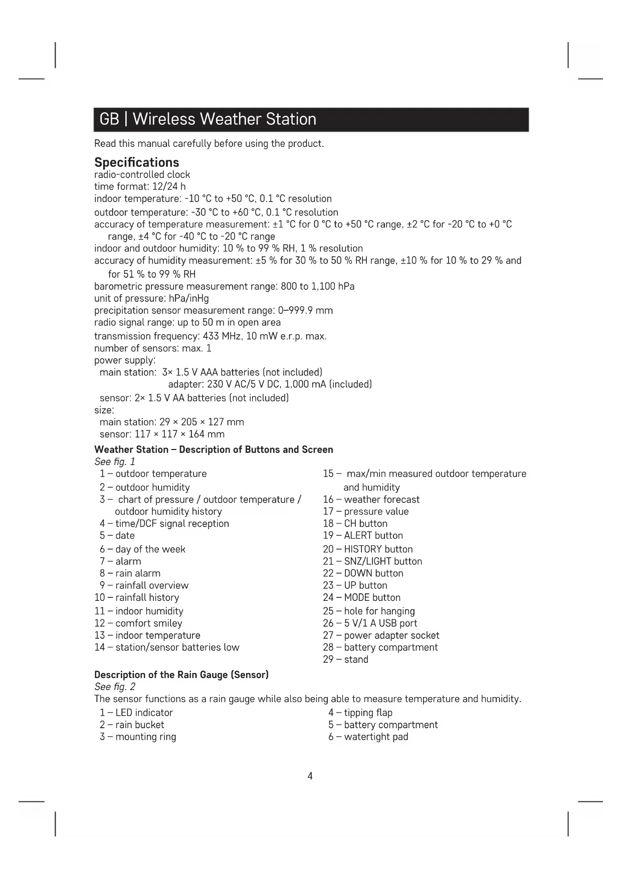
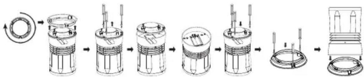
Assembly/Installation of the Rain Gauge (Sensor)
- Turn the rain bucket clockwise.
- Remove the paper card from the tipping flap.
- Fit the rain bucket back on by turning it counter-clockwise; you should hear a click.
flowchart
graph LR
    A["Circular Component"] --> B["Mechanical Assembly"]
    B --> C["Device with Press Icon"]
    style A fill:#f9f,stroke:#333
    style B fill:#ccf,stroke:#333
    style C fill:#cfc,stroke:#333
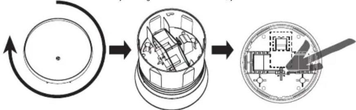
- Turn the sensor upside down.
- Turn the mounting ring clockwise.
- Remove the 3 screws on the watertight pad and detach it.
- Underneath the pad is the battery compartment; insert 2× 1.5 V AA batteries.
- Replace the pad.
- Affix the mounting ring to the location of choice using the screws and fit the sensor onto it by turning counter-clockwise; you should hear a click.
flowchart
graph LR
    A["Initial Component"] --> B["Exploded Component"]
    B --> C["Internal Component"]
    C --> D["Final Assembly"]

    subgraph Initial Components
        E["Conical Component"] --> F["Arrow to Ring"]
        G["Internal Component"] --> H["Arrow to Ring"]
        I["Internal Component"] --> J["Arrow to Ring"]
        K["Internal Component"] --> L["Arrow to Ring"]
        M["Internal Component"] --> N["Arrow to Ring"]
        O["Internal Component"] --> P["Arrow to Ring"]
        Q["Internal Component"] --> R["Arrow to Ring"]
        S["Internal Component"] --> T["Arrow to Ring"]
        U["Internal Component"] --> V["Arrow to Ring"]
        W["Internal Component"] --> X["Arrow to Ring"]
        Y["Internal Component"] --> Z["Arrow to Ring"]
        AA["Internal Component"] --> AB["Arrow to Ring"]
        AC["Internal Component"] --> AD["Arrow to Ring"]
        AE["Internal Component"] --> AF["Arrow to Ring"]
        AG["Internal Component"] --> AH["Arrow to Ring"]
        AI["Internal Component"] --> AJ["Arrow to Ring"]
        AK["Internal Component"] --> AL["Arrow to Ring"]
        AM["Internal Component"] --> AN["Arrow to Ring"]
        AO["Internal Component"] --> AP["Arrow to Ring"]
        AQ["Internal Component"] --> AR["Arrow to Ring"]
        AS["Internal Component"] --> AT["Arrow to Ring"]
        AU["Internal Component"] --> AV["Arrow to Ring"]
        AW["Internal Component"] --> AX["Arrow to Ring"]
        AY["External Component"] --> AZ["Arrow to Ring"]
Getting Started
- Insert batteries first into the wireless sensor (2× 1.5 V AA), then into the weather station (3× 1.5 V AAA) and plug the power adapter into the station.
- When inserting the batteries, make sure the polarity is correct to avoid damaging the weather station or sensor. Only use 1.5 V alkaline batteries of the same type; do not use rechargeable 1.2 V batteries. The lower voltage may cause both of the units to not function.
- Place the two units next to each other. The weather station will detect the sensor signal within 3 minutes. If signal from the sensor is not detected, long press the CH button on the weather station to repeat the search.
- If the outdoor temperature reading disappears from the screen, long press the CH button on the station and remove and reinsert the batteries in the sensor. The weather station will reset all values and repeat the search for sensor signal.
- We recommend placing the sensor on the north side of the house. The range of the sensor may decrease substantially in areas with a large number of obstacles.
- To ensure correct measurement, the sensor must be placed in an elevated position (at least 1.5 m) onto a horizontal surface and outside of buildings and structures. The sensor must be mounted firmly to prevent its damaging.
-
Place the sensor in a place where rain falls directly. The sensor should be placed in an open space at a sufficient distance from surrounding trees and bushes.
-
Rainwater must be able to continuously and freely flow out of the sensor. Always check that water is not accumulating in the bottom of the sensor.
- When choosing a suitable place to mount the sensor, check that the main station is within range of the sensor. The range of the sensor may decrease substantially in areas with a large number of obstacles.
- Do not place the sensor onto metal objects; doing so will reduce the transmission range.
- If the low battery icon is displayed on the station's screen, replace batteries in the sensor or weather station.
Radio-Controlled Clock (DCF77)
After being registered by the wireless sensor, the weather station will automatically start searching for DCF77 signal (DCF for short) for 7 minutes; the "icon flashes. During the search, no other items on the display will be updated and the buttons will be disabled (except SNOOZE/LIGHT). Once the signal is detected, the icon will stop flashing ("stays on the screen") and current time will be displayed. If no signal is detected, the DCF icon will not be shown.
Long-press the DOWN button to search for DCF signal again. To cancel the search for signal, long-press the DOWN button again. DCF signal will be synchronised daily between 2:00 and 3:00 am.
During daylight saving time, the DcST will be displayed.
Note: If the weather station detects DCF signal but the current time on the display is incorrect (e.g. shifted ±1 hour), you must set the correct time zone for the country where you are using the station, (see Manual Settings).
In standard conditions (at safe distance from sources of interference, such as TV sets or computer monitors), the reception of time signal takes several minutes. If the weather station does not detect the signal, follow these steps:
- Move the weather station to another location and try to detect the DCF signal again.
- Check the distance of the clock from sources of interference (computer monitors or television sets). The distance should be at least 1.5 to 2 m during the reception of signal.
- When receiving DCF signal, do not place the weather station near metal doors, window frames and other metal structures or objects (washing machines, dryers, refrigerators, etc.).
- In reinforced concrete structures (cellars, high-rise buildings, etc.), the reception of DCF signal is weaker, depending on the conditions. In extreme cases, place the weather station close to a window in the direction of a transmitter.
Reception of DCF radio signal is affected by the following factors:
- thick walls and insulation, basements and cellars;
- inadequate local geographical conditions (these are difficult to assess in advance);
• atmospheric disturbances, thunderstorms, electrical appliances with no interference elimination, television sets and computers located near the DCF receiver.
Manual Settings
- Long-press the MODE button.
- Then, repeatedly press the MODE button to choose settings for: time zone - 12/24 h - hours - minutes - year - month - day. You can navigate between the values by pressing the MODE button, set values using UP/DOWN.
The calendar is in English.
Setting °C/°F Temperature Unit
Repeatedly pressing the UP button switches temperature units between ^ C/ ^ F.
Setting Unit of Pressure/Precipitation
Repeatedly pressing the DOWN button sets the pressure and precipitation units to inHg/inches or hPa/mm.
Atmospheric Pressure
The current pressure value is displayed in field no. 17.
Repeatedly pressing the DOWN button sets the unit of pressure to inHg or hPa.
Moving the weather station to another place will affect the measured values.
Measurement will stabilise within 12 hours of battery insertion or relocation of the weather station.
Comfort Level Indicator – Smiley
Displayed in field no. 12.

Comfortable environment

Comfortable environment

Dry environment

Dry environment

Wet environment
Temperature and Humidity Trend
| Temperature and humidity trend indicator | |||
| rising constant | falling |
Weather Trend
| Weather trend indicator | |||
| improvement no changes worsening | |||
Displaying of Measured Precipitation and Max/Min Temperature and Humidity Values
By default, the precipitation value displayed on the screen is for the current day (today's).
Repeatedly pressing the HISTORY button will display:
Precipitation – yesterday, this week, this month, this year, last year, max/min indoor temperature/humidity, max/min outdoor temperature/humidity.
Note:
To manually erase the memory of measured temperature and humidity values, long-press the HISTORY button while viewing the history of measurements.
When the maximum precipitation value of 999.99 mm is exceeded, 10.XX will appear on the screen and the history of measurements will need to be erased.
If you wish to erase the history of precipitation measurements, disconnect the adapter/remove the batteries from the weather station (the weather station will have to be manually set again).
Note to measured precipitation values:
Light rain = 0.25 mm/hour
Slight rain = 1 mm/hour
Rain = 4 mm/hour
Heavy rain = 16 mm/hour
Rainstorm = 35 mm/hour
Heavy rainstorm = 100 mm/hour
Chart of Pressure / Outdoor Temperature / Outdoor Humidity History
Field no. 3 shows a chart of pressure / outdoor temperature / outdoor humidity history over up to the last 12 hours.
The chart is animated – the values are displayed automatically and repeatedly every 5 seconds.
The animation cannot be turned off and the order/setting of values cannot be changed.
If you wish to erase the history of measurements, disconnect the adapter/remove the batteries from the weather station (the weather station will have to be manually set again).
Setting an Alarm
Press the MODE button; AL will appear on the screen.
Then, long-press the MODE button again; the time setting will start flashing.
Use the UP/DOWN buttons to set the alarm time.
Confirm the set value by pressing MODE.
To activate the alarm, press MODE again (AL appears on the screen) and then UP/DOWN.
If 🚙 appears on the screen, the alarm is activated. Pressing the UP/DOWN button again deactivates the alarm; the 🚙 con disappears.
Snooze Function
The ringing of the alarm can be delayed by 5 minutes using the SNZ/LIGHT button located at the top of the weather station.
Press the button when the alarm starts ringing. The icon will be flashing.
To cancel SNOOZE mode, press any other button – the icon will stop flashing and will remain on the screen.
The alarm will trigger again the next day.
Station Screen Illumination
1. When powered via adapter:
Permanent screen illumination is automatically set.
Repeatedly pressing the SNZ/LIGHT button switches between 3 illumination levels (100 % - 50 % - off).
2. When powered only by 3× 1.5 V AAA batteries:
Screen illumination is off. Pressing the SNZ/LIGHT button will turn screen illumination on for 10 seconds, then it turns off again. When the station is only powered by batteries, permanent screen illumination cannot be activated!
Note:
The inserted batteries serve as backup for the measured/set data.
If batteries are not inserted and you unplug the adapter, all data will be erased.
5 V/1 A USB Port
The port is used for charging compatible USB devices. The charging cable is not included.
The USB port only functions when the station is powered from the adapter.
Setting Outdoor Rain and Temperature Alert
Long-press the ALERT button; rain alert setting will start flashing.
Repeatedly pressing the UP/DOWN buttons activates on or deactivates the rain alert.
Confirm by pressing ALERT; the precipitation value will start flashing.
Repeatedly press the UP/DOWN buttons to set the alert value of your choice (0.25 to 999.99 mm).
Confirm by pressing alert ALERT; the station switches to temperature alert settings.
Repeatedly pressing the UP/DOWN buttons deactivates the maximum temperature alert Hi
minimum temperature alert . Hi Lo
Confirm by pressing ALERT; the maximum temperature value will start flashing.
Repeatedly press the UP/DOWN buttons to set the alert value of your choice.
Confirm by pressing ALERT; the minimum temperature value will start flashing.
Repeatedly press the UP/DOWN buttons to set the alert value of your choice and confirm by pressing ALERT.
After the set limit is exceeded, the station will play a sound and the value will be flashing.
Pressing any button on the screen cancels the alert sound, but the icon of an active alert will continue flashing.
Once temperature drops below the set limit, the icon on the screen will stop flashing.
If you do not wish to wait for the value to drop, you must adjust the value or deactivate the alert.
Weather Forecast
The station uses changes in atmospheric pressure to forecast weather for the next 12–24 hours for an area within the radius of 15–20 km.
The accuracy of weather forecast is 70–75 %. The forecast icon is displayed in field no. 16.
As the weather forecast may not be 100 % accurate, neither the manufacturer nor the seller can be held responsible for any loss caused by an incorrect forecast.
When you first set or reset the weather station, it takes approximately 12 hours before the weather station begins forecasting correctly.
Weather Forecast Icons
 |  |  |  |  |
| Sunny Cloudy | Overcast Snow Rain |
Upkeep and Maintenance
The product is designed to serve reliably for many years if used properly. Here are some tips for proper operation:
- Read the manual carefully before using the product.
- Do not expose the product to direct sunlight, extreme cold and humidity and sudden changes in temperature. This would reduce measuring accuracy. Do not place the product in locations prone to vibration and shocks – may cause damage.
- Do not subject the product to excessive force, impacts, dust, high temperatures or humidity – doing so may cause malfunction, shorten battery life, damage batteries and deform plastic parts.
- Do not expose the product to rain or moisture if it is not designed for outdoor use.
- Do not place any open flame sources on the product, e.g. a lit candle, etc.
- Do not place the product in places with inadequate air flow.
- Do not insert any objects into the product's vents.
- Do not tamper with the internal electrical circuits of the product – doing so may damage the product and will automatically void the warranty. The product should only be repaired by a qualified professional.
- To clean the product, use a slightly moistened soft cloth. Do not use solvents or cleaning agents – they could scratch the plastic parts and cause corrosion of the electric circuits.
- Do not immerse the product in water or other liquids.
• The product may not be exposed to dripping or splashing water.
- In the event of damage or defect of the product, do not perform any repairs by yourself. Have it repaired in the shop where you bought it.
- This device is not intended for use by persons (including children) whose physical, sensory or mental disability or whose lack of experience or knowledge prevents them from using it safely. Such persons should be instructed in how to use the device and should be supervised by a person responsible for their safety.

Do not dispose with domestic waste. Use special collection points for sorted waste. Contact local authorities for information about collection points. If the electronic devices would be disposed on landfill, dangerous substances may reach groundwater and subsequently food chain, where it could affect human health.
Hereby, EMOS spol. s r. o. declares that the radio equipment type E8670 is in compliance with Directive 2014/53/EU. The full text of the EU declaration of conformity is available at the following internet address: http://www.emos.eu/download.
flowchart
graph LR
    A["Circular Component"] --> B["Mechanical Assembly"]
    B --> C["Final Assembly with Tool"]
flowchart
graph LR
    A["Circular Circulation"] --> B["Mechanical Assembly"]
    B --> C["Final Product Inspection with Tool"]
flowchart
graph LR
    A["Wheel with valve"] --> B["Actuator with valve"]
    B --> C["Engine cylinder with actuator"]
    C --> D["Actuator with valve"]
    D --> E["Engine cylinder with actuator"]
    E --> F["Engine cylinder with actuator"]
flowchart
graph LR
    A["Rotator with arrow"] --> B["Actuator with cylindrical body"]
    B --> C["Actuator with cylindrical body and internal components"]
    C --> D["Actuator with cylindrical body and internal components"]
    D --> E["Actuator with cylindrical body and internal components"]
    E --> F["Actuator with cylindrical body and internal components"]
    F --> G["Final cylinder assembly with end caps"]
flowchart
graph LR
    A["Start"] --> B["Rotating Circular Component"]
    B --> C["Mechanical Assembly"]
    C --> D["Final Assembly with Component"]
urni format: 12/24 h
notranja temperatura: -10 °C do +50 °C z ločljivostjo 0,1 °C
flowchart
graph LR
    A["Circular Component"] --> B["Device with Internal Components"]
    B --> C["Mechanical Component with Component 1"]
flowchart
graph LR
    A["Circular Component"] --> B["Mechanical Assembly"]
    B --> C["Device with lever mechanism"]
- Okrenite senzor naopako.
- Okrenite ugradbeni prsten u smjeru kazaljke na satu.
- Uklonite 3 vijka na vodonepropusnoj podlozi i odvojite je.
- Ispod podloge je baterijski odjeljak; umetnite 2 baterije AA od 1,5 V.
- Zamijenite podlogu.
- Pričvrstite ugradbeni prsten na željeno mjesto pomoću vijaka i postavite senzor na njega okretanjem u smjeru suprotno od kazaljke na satu; trebali biste čuti klik.
flowchart
graph LR
    A["Engine"] --> B["Actuator 1"]
    B --> C["Actuator 2"]
    C --> D["Actuator 3"]
    D --> E["Actuator 4"]
    E --> F["Actuator 5"]
    F --> G["Actuator 6"]
    G --> H["Actuator 7"]
    H --> I["Actuator 8"]
Početak rada
Indikator razine ugode – Smješko
Jaka kiša = 16 mm/sat
Oluja s kišom = 35 mm/sat
Snažna oluja s kišom = 100 mm/sat
flowchart
graph LR
    A["Circular Component"] --> B["Middle Column"]
    B --> C["Final Assembly with Component"]
flowchart
graph LR
    A["Initial Stator"] --> B["Step 1: Internal Stator"]
    B --> C["Step 2: Stator with Internal Stator"]
    C --> D["Step 3: Stator with Internal Stator"]
    D --> E["Step 4: Stator with Internal Stator"]
    E --> F["Step 5: Stator with Internal Stator"]
    F --> G["Final Stator with Internal Stator"]
Inbetriebnahme
flowchart
graph LR
    A["Start"] --> B["Rotating Circular Surface"]
    B --> C["Interior Design"]
    C --> D["Final Assembly with Device Component"]
flowchart
graph LR
    A["Circular Component"] --> B["Mechanical Assembly"]
    B --> C["Device with Blade"]
flowchart
graph LR
    A["Circular Circular Cycle"] --> B["Interior Space Layout"]
    B --> C["Final Installation with lightning bolt"]
flowchart
graph LR
    A["Initial Component"] --> B["Intermediate Component"]
    B --> C["Final Assembly"]

    subgraph Initial
    direction LR
    A -->|Upward Roll| B
    B -->|Downward Roll| C
    end

    subgraph Intermediate
    direction LR
    B -->|Upward Roll| C
    end

    subgraph Final Assembly
    direction LR
    B -->|Downward Roll| C
    end
Pradžia
flowchart
graph LR
    A["Circular Circular Cycle"] --> B["Interior Space Layout"]
    B --> C["Device Placement with lightning bolt"]
flowchart
graph LR
    A["Initial Component"] --> B["Intermediate Component"]
    B --> C["Final Assembly"]

    subgraph Initial
    direction LR
    A -->|Upward Roll| A
    end

    subgraph Intermediate
    direction LR
    B -->|Downward Roll| B
    end

    subgraph Final Assembly
    direction LR
    C -->|Downward Roll| C
    end

    style Initial fill:#f9f,stroke:#333
    style Intermediate fill:#bbf,stroke:#333
    style Final Assembly fill:#dfd,stroke:#333
Darba sākšana
flowchart
graph LR
    A["Circular Component"] --> B["Device Interior"]
    B --> C["Device Interior with Internal Components"]
    C --> D["Device Interior with External Component"]
flowchart
graph LR
    A["Initial Component"] --> B["Intermediate Component"]
    B --> C["Final Assembly"]

    subgraph Initial
    direction LR
    A -->|Upward Roll| A
    end

    subgraph Intermediate
    direction LR
    B -->|Downward Roll| B
    end

    subgraph Final Assembly
    direction LR
    C -->|Downward Roll| C
    end

    style Initial fill:#f9f,stroke:#333
    style Intermediate fill:#bbf,stroke:#333
    style Final Assembly fill:#dfd,stroke:#333
Alustamine
flowchart
graph LR
    A["Circular Component"] --> B["Middle-Pane Container"]
    B --> C["Final Assembly with Component"]
flowchart
graph LR
    A["Initial Component"] --> B["Intermediate Component"]
    B --> C["Final Component"]
    C --> D["Final Ring with Two Detons"]
Начало
station principale: 3× pile de 1,5 V de type AAA (pas fournies)
adaptateur AC 230 V/DC 5 V, 1000 mA (fourni)
station principale: 29 × 205 × 127 mm
flowchart
graph LR
    A["Circular Component"] --> B["Mechanical Housing"]
    B --> C["Device with Tool"]
flowchart
graph LR
    A["Initial Component"] --> B["Intermediate Component"]
    B --> C["Final Assembly"]

    subgraph Initial
    direction LR
    A -->|Upward Roll| B
    B -->|Downward Roll| C
    end

    subgraph Intermediate
    direction LR
    B -->|Upward Roll| C
    end

    subgraph Final Assembly
    direction LR
    B -->|Downward Roll| C
    end
Messa in servizio
Icona comfort – smiley
flowchart
graph LR
    A["Circular Component"] --> B["Mechanical Device"]
    B --> C["Final Component with Tool"]
flowchart
graph LR
    A["Circle"] --> B["Interior Space Expansion"]
    B --> C["Final Installation with Tool"]