DUTEST pro - Multimeter BENNING - Free user manual and instructions
Find the device manual for free DUTEST pro BENNING in PDF.

User questions about DUTEST pro BENNING
0 question about this device. Answer the ones you know or ask your own.
Ask a new question about this device
Download the instructions for your Multimeter in PDF format for free! Find your manual DUTEST pro - BENNING and take your electronic device back in hand. On this page are published all the documents necessary for the use of your device. DUTEST pro by BENNING.
USER MANUAL DUTEST pro BENNING
natural_image
Illustration of two different types of electrical probes with no text or symbolsBENNING
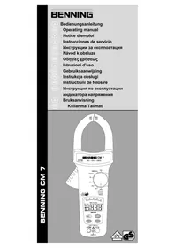
Before using the DUTEST ^® pro continuity tester: Please read the operating manual and absolutely observe the safety instructions!
Table of contents
- Safety instructions
- Device description
- Functional test
- Continuity and diode test
- External-voltage and polarity indication
- Single-pole external conductor test (phase)
- Cable break detector
- LED torch
- Battery replacement
- Technical data
- General maintenance
- Environmental protection
1. Safety instructions

Attention! Magnets might affect the correct functioning of cardiac pacemakers and implanted defibrillators. As a user of such medical devices, keep a sufficient distance to the magnet.
- During the tests, touch the device at the insulated test probes ⑦ and ⑧ only and do not touch the testing electrodes ⑥!
- Check the device for correct functioning immediately before and after using it (see chapter 3)! Do not use the device, if one or more indications are not working or if it does not seem to be ready for operation!
- If it is assumed that safe operation is no longer possible, the device must be switched off immediately.
- Absolutely prevent the device from getting wet and avoid any water condensation at the device. Moreover, the device must be protected against contamination and damaging!
- The device does not work with the battery being exhausted!
- The device must be used within the stated nominal voltage range and in electrical installations of up to 400 V AC/DC only!
- The device must be used only in electric circuits of overvoltage category CAT III with max. 300 V for phase-to-earth measurements. For measurements within measuring category III, the protruding conductive part of a testing electrode ⑥ of the measuring line must not be longer than 4 mm. Before carrying out measurements within measuring category III, the enclosed attachable protective caps marked with CAT III must be pushed onto the testing electrodes ⑥ for user protection purposes.
- Please observe that work on live parts and electrical components of all kinds is dangerous! Even low voltages of 30 V AC and 60 V DC may be dangerous to human life!
- Do not operate the device with the battery compartment being open.
- The device is designed for being used by qualified electricians and under safe working conditions.
- Do not dismantle the device!
Attention!
Immediately before use, make absolutely sure that the system part to be tested is free of voltage! For this purpose, use a two-pole voltage tester.
Attention!
The device is provided with a high-power LED torch. Do not look directly or indirectly via reflecting surfaces
into the LED beam. An LED beam might cause irreparable damage to your eyes.
Symbols on the device:
| Symbol Meaning | |
 | Attention! Please observe documentation!This symbol indicates that the information provided in the operating manual must be complied with in order to avoid risks. |
 | Direct and alternating voltage (DC/AC) |
| [06H7] | Earth (voltage to earth) |
| [32TX] | This symbol shows the orientation of the batteries for inserting them with correct polarity. |
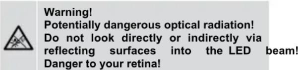
 | Warning! Potentially dangerous optical radiation!Do not look directly into the light beam!Danger to your retina! |
 | Attention! Magnets might affect the correct functioning of cardiac pacemakers and implanted defibrillators. As a user of such medical devices, keep a sufficient distance to the magnet. |
2. Device description
① Yellow LED for continuity tests up to R ≤ 100 to 200
② Yellow LED for continuity tests up to R ≤ 1 k
③ Yellow LED for continuity tests up to R ≤ 10 kΩ
4 Red (+) LED of the external-voltage indication (lights up),
+ positive pole of the polarity indication (lights up), ✦ external conductor test (phase) and cable break detector (flashes)
5 Red (-) LED of the external-voltage indication (lights up),
- negative pole of the polarity indication (lights up)
6 Testing electrodes with attachable protective caps
⑦ (+) test probe (red)
⑧ (-) test probe (black)
9 Measuring line
10 High-power LED torch
11 Push-button
12 Catch of the battery compartment cover
13 Battery compartment cover with magnet, belt clip and technical data
14 Sensor of the cable break detector
3. Functional test
- Check the device for correct functioning immediately before and after using it!
- Press and hold the push-button ⑪ for approx. 5 seconds to check all LEDs, the LED torch and the buzzer for correct functioning.
- Short-circuit the test probes 7 and 8 to test the internal measuring circuit, the measuring lines and the batteries. The buzzer must sound and the LEDs 1, 2 and 3 for continuity test must light up.
- Please replace the batteries as soon as the LEDs ①, ② and ③ are flashing during the continuity test.
- Test the LEDs ④ and ⑤ of the external-voltage indication as well as the correct functioning of the single-pole external conductor test (phase) ④ with familiar voltage sources, e.g. with a 230 V socket.
- Do not use the device, if not all functions are working properly!
4. Continuity and diode test
- The continuity and diode test must be carried out on system parts which are free of voltage. If necessary, capacitors have to be discharged.
- Apply the two test probes ⑦ and ⑧ to the system parts to be tested.
- In case of continuity (resistance value R ≤ 100 to 200 ), an acoustic signal is emitted yellow LEDs ①, ② and ③ light up.
- The resistance value can be roughly estimated by means of the LED step indicator ①, ② and ③.
| Resistance (R) | ≤ 100 -200 | ≤ 1 k | ≤ 10 k | >10 k ≤ 100 k |
| Buzzer | ||||
| 1 LED 100 | ● 1. | ● ↓ | ||
| 2 LED 1 k | ● ● | 2. ● ↓ | ||
| 3 LED 10 k | ● ● | ● 3. | ● ↓ |
- To determine the conducting direction of a diode, apply the black (-) test probe ⑧ to the cathode and the red (+) test probe ⑦ to the anode of the diode. The conducting direction has been determined as soon as the yellow LEDs ①, ② and ③ light up (running light).
- If a voltage is applied to the test point, the device warns the user of an external voltage applied by means of the red LEDs ④ and/or ⑤ lighting up. In this case, stop the test immediately and ensure the absence of voltage!
Setting the buzzer volume
The buzzer volume can be set in four steps. Step 1 (low), step 2 (medium), step 3 (high) and step 4 (very high). In step 5, the buzzer is OFF and the LED torch is ON.
To set the volume, short-circuit the test probes ⑦ and ⑧ and press and hold the push-button ⑪ until the desired volume is set. The buzzer volume set remains stored until it is changed the next time.
5. External-voltage and polarity indication
- Apply BOTH test probes ⑦ and ⑧ to the system parts to be tested.
- The LEDs ④ and ⑤ for external-voltage indication detect DC (——) and AC voltages (\~) within a range from 6 to 400 V.
- AC voltages ( ) are displayed by the (+) LED ④ and the (-) LED ⑤ lighting up simultaneously.
- DC voltages ( ) are displayed by the (+) LED ④ or the (-) LED ⑤ lighting up. The (+) LED ④ lights up, if the positive pole of the voltage source is applied to the red (+) test probe ⑦ and the negative pole of the voltage source is applied to the black (-) test probe ⑧.
Attention!
The external-voltage indication does not replace a two-pole voltage tester for determining the absence of voltage.
Additional indication for external-voltage detection (two-pole)
If the buzzer is switched on during the continuity test, a pulsating acoustic signal warns of an external voltage applied. If the buzzer is switched off during the continuity test, the LED torch 10 will flash as soon as an external voltage is applied. The additional indication (pulsating acoustic signal or flashing LED torch 10) can be deactivated. For this, apply the two test probes 7 and 8 to a voltage source (6 V to 400 V) and press the push-button 11 for approx. 1 second. To activate the additional indication (pulsating acoustic signal or flashing LED torch 10), repeat this procedure.
6. Single-pole external conductor test (phase)
- Apply the black (-) test probe ⑧ OR the red (+) test probe ⑦ to the system part to be tested. During the single-pole external conductor test (phase), make absolutely sure not to touch the bare testing electrode ⑥ of the other test probe and make sure that it remains contactless.
and the red LED 4 flashes, the external conductor (phase) of an AC voltage is applied to this system part.
Additional indication for external conductor test
If required, an additional indication (pulsating acoustic signal or flashing LED torch 10) can be activated for the external conductor test. To activate the additional indication, connect the black (-) test probe 8 OR the red (+) test probe 7 to the external conductor (phase) of a socket and press the push-button 11 for approx. 1 second. To deactivate the additional indication, press the push-button 11 once again. The additional indication (pulsating acoustic signal or flashing LED torch 10) depends on the buzzer volume set for the continuity test (see chapter 4).
Note:
The single-pole external conductor test (phase) can be carried out in an earthed mains from 230 V, 50 Hz / 60 Hz (phase to earth) on.
7. Cable break detector
- The cable break detector 14 is intended for the non-contact localization of cable breaks on exposed live lines.
- Pass the detector 14 over a live line (e.g. a cable reel or a chain of lights) from the feeding point (phase) in direction of other end of the line.
- As long as the line is not interrupted, the red LED 4 is flashing.
- The point of the cable break has been localized as soon as the red LED 4 goes out.
Additional indication for cable break detector
An additional indication (pulsating acoustic signal or flashing LED torch 10) activated for the single-pole external conductor test (see chapter 6) is also activated for the cable break detector.
Note:
The cable break detector can be used in earthed mains from 230 V, 50 Hz/60 Hz (phase to earth) on.
8. LED torch
text_image
Warning! Potentially dangerous optical radiation! Do not look directly or indirectly via reflecting surfaces into the LED beam! Danger to your retina!- The device is provided with a high-power LED torch 10 with can be switched on and off by pressing the push-button 11.
- It is switched off automatically after approx. 2 minutes.
Setting the luminosity
The luminosity of the LED torch 10 can be set in four steps.
Step 1 (25 %), step 2 (50 %), step 3 (75 %) and step 4 (100 %). To set the luminosity, press and hold the push-button until the desired luminosity is set. The highest step 4 (100 %) will be confirmed by means of an acoustic signal. The luminosity set remains stored until it is changed the next time.
9. Battery replacement
- Do not apply voltage to the device when the battery compartment is open!
- The battery compartment is located on the back of
the device.
- Slightly press down the catch 12 by means of a screwdriver and push off the battery compartment cover 13 in downward direction at the same time.
- Replace the exhausted batteries by three new ones of type AA (LR06). Make sure that the new batteries are inserted with correct polarity!
- Push the battery compartment cover 13 back onto the housing until the catch 12 locks into place with an audible click.
Note:
The battery compartment cover 13 is provided with an integrated magnet and a belt clip for attachment of the device.
10. Technical data:
- Built and tested according to: DIN EN 61010-1 and -031, IEC 61010-1 and -031, DIN EN 62471
- Protection against external voltages: max. 400 V≈, 50 Hz / 60 Hz
- Measuring category: CAT III 300 V to earth
- Continuity test: acoustically by means of buzzer for measuring resistances R ≤ 100 to 200
visually by means of three LED steps:
LED 100 Ω for measuring resistances R ≤ 100 Ω to 200 Ω
LED 1 kΩ for measuring resistances R ≤ 1 kΩ LED 10 kΩ for measuring resistances R ≤ 10 kΩ
- Range of tolerance: ± 20 % of the maximum value of the LED step
- Buzzer volume: step 1 (low), step 2 (medium), step 3 (high) and step 4 (buzzer: OFF, LED torch: ON).
- Open-circuit voltage: ≤ 4.5 V
- Testing current: ≤ 30 μA
- Diode test: \~ 1.5 V, max. 30 μA
- External-voltage detection: 6 V - 400 V AC / DC, 50 Hz / 60 Hz
- Internal resistance: 166 kΩ
- Current consumption: I _s < 3.5 mA (400 V)
- Polarity indication: from ± 6 V on
- External conductor test (phase): U _n ≥ 230 V, 50 Hz / 60 Hz
- Cable break detector: U _n ≥ 230 V, 50 Hz / 60 Hz
- Contamination level: 2
- Protection category: IP 40 (DIN VDE 0470-1 IEC / EN 60529)
4 – first index: protection against access to dangerous parts and protection against solid impurities of a diameter > 1.0 mm
0 – second index: no protection against water
- Battery: 3 x 1.5 V batteries of type AA (LR06)
- Weight: approx. 130 g
- Measuring line with test handles: approx. 1,000 mm
- Operating temperature range: - 15 °C to + 55 °C
- Storage temperature range: - 15 °C to + 55 °C
- Relative air humidity: 20 % to 80 %
- Luminosity of the LED torch: step 1 (25 %), step 2 (50 %), step 3 (75 %), step 4 (100 %)
11. General maintenance
Clean the exterior of the device with a clean dry cloth. If there is contamination or deposits in the area of the battery or the battery housing, clean these areas as well by means of a dry cloth.
If the device is stored for a longer period of time, remove the batteries from the device!
12. Environmental protection

At the end of product life, dispose of the unserviceable device as well as used batteries via appropriate collecting facilities provided in your community.