MM 3 - Multimeter BENNING - Free user manual and instructions
Find the device manual for free MM 3 BENNING in PDF.
| Product type | Digital multimeter |
| Brand | BENNING |
| Model | MM 3 |
| Dimensions (without frame) | 175 x 84 x 31 mm |
| Dimensions (with frame) | 192 x 95 x 50 mm |
| Weight (without frame) | 340 g |
| Weight (with frame) | 550 g |
| Power supply | 9 V battery (IEC 6LR61) |
| Display | 3½ digits, 20 mm, max value 1999 |
| Measurement functions | DC/AC voltage, DC/AC current, resistance, diodes, continuity, capacitance, frequency |
| Overvoltage category | 300 V CAT III, 600 V CAT II |
| Protection | Fuses 1 A/500 V (ref. 749669) and 16 A/500 V (ref. 749770) |
| Protection rating | IP 30 |
| Working temperature | 0 °C to 50 °C (depending on humidity) |
| Storage temperature | -20 °C to +60 °C |
| Relative humidity | 80% max (0-30 °C), 75% max (30-40 °C), 45% max (40-50 °C) |
| Double insulation | Yes (protection class II) |
| Maintenance | Clean with a dry cloth; do not use solvents |
| Spare parts | Fuses 1 A and 16 A (ref. 749769, 749770), 9 V battery |
| Supplied accessories | Measuring leads, protective frame, carrying case, battery, fuses, manual |
Frequently Asked Questions - MM 3 BENNING
User questions about MM 3 BENNING
0 question about this device. Answer the ones you know or ask your own.
Ask a new question about this device
Download the instructions for your Multimeter in PDF format for free! Find your manual MM 3 - BENNING and take your electronic device back in hand. On this page are published all the documents necessary for the use of your device. MM 3 by BENNING.
USER MANUAL MM 3 BENNING
Multilingual manuals on included CD and at
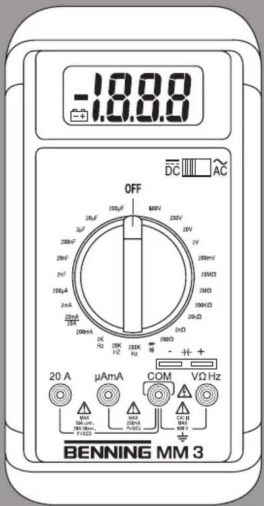
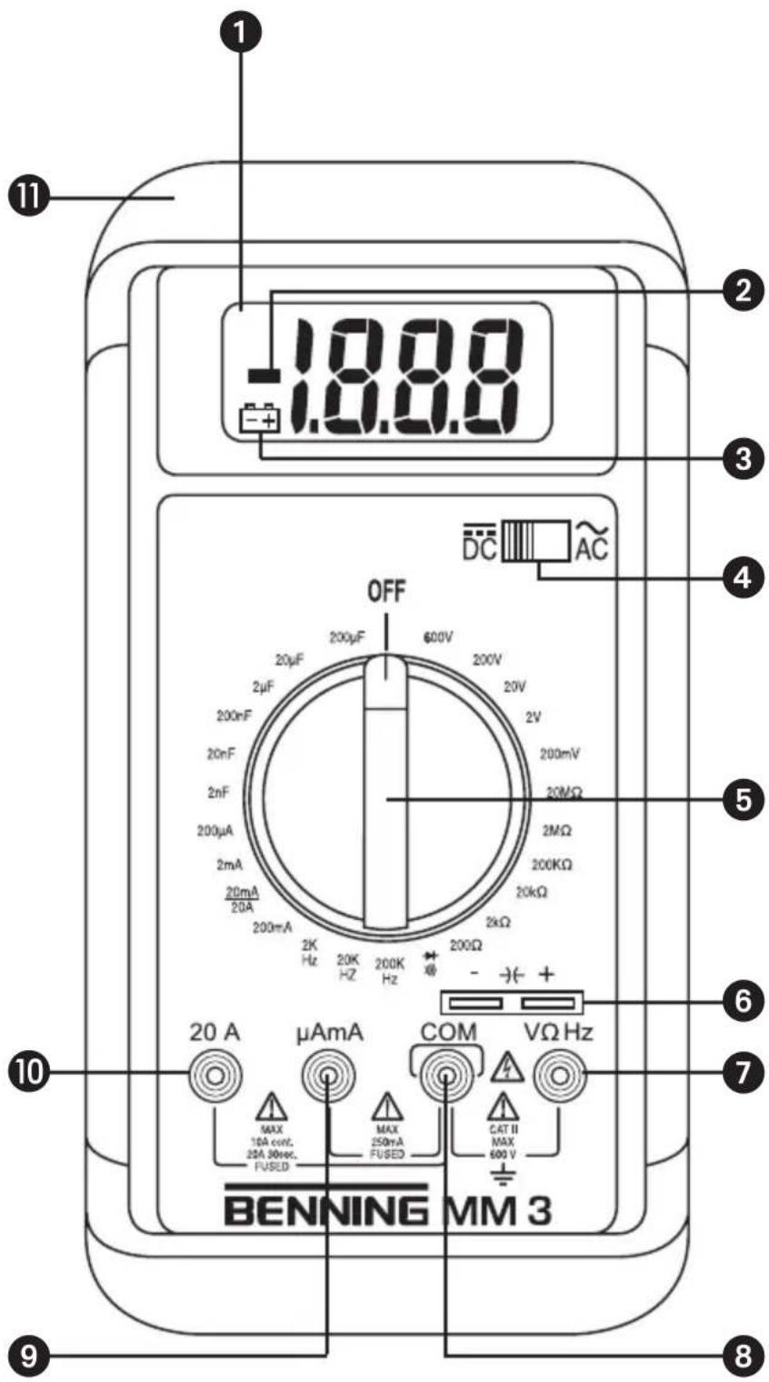
Bild 1: Gerätefrontseite
Fig. 1: Front tester panel
Fig. 1: Panneau avant de l'appareil
Fig. 1: Parte frontal del equipo
Obr.1: Predni strana pristroje
III. 1: Lato anterioi apparechio
Fig. 5: AC current measurement
Fig. 6: Resistance measurement
Digital Multimeter for
- DC voltage measurement
- AC voltage measurement
DC current measurement - AC current measurement
- Resistance measurement
- Diode testing
- Continuity testing
- Capacitance measurement
- Frequency measurement
Index of Contents
- Operating instructions
- Safety instructions
- Scope of delivery
- Meter description
- General Specifications
- Ambient Conditions
- Electrical Specifications
- Measuring with BENNING MM 3
- Maintenance
- How to use the protective rubber holster
- Technical data of the measuring accessories
12.Environmentalnote
1. Operating Instructions
This operating manual is intended for
- electrical professionals
- qualified electrotechnical persons
The BENNING MM 3 is designed for measuring in dry conditions. It must not be used on electrical circuits with a rated voltage greater than 600V AC/DC (for details refer to "Ambient Conditions" section).
The following symbols appear in this manual and on the BENNING MM 3:

This symbol indicates dangerous voltage.

This symbol indicates warnings and cautions to be observed when using the BENNING MM 3 (refer to manual!)

This symbol on the BENNING MM 3 indicates that the BENNING MM 3 has double insulation (Protection Class II)

This symbol on the BENNING MM 3 indicates the unit contains built-in fuses.

This symbol appears in the display when the battery is low.

This symbol indicates the "Continuity testing" mode is selected. The buzzer sounds for acoustic test results.

This symbol indicates the "Diode testing" mode is selected.

(DC) Direct voltage or current.

(AC) Alternating voltage or current.
Ground (voltage against earth)

Capacitor (terminals)
2. Safety note
The instrument is built and tested in accordance with
DIN VDE 0411 part 1/ EN 61010-1
and has left the factory in perfectly safe technical condition.
To maintain this condition and ensure safe operation of the multimeter, the user must observe the notes and warnings given in these instructions at all times.

The unit may be used only in power circuits within the overvoltage category II with a conductor for 600V max. to earth, or within overvoltage category III with a conductor for 300V against ground.
Only use suitable measuring leads for this. With measurements within measurement category III, the projecting conductive part of a contact tip of the measuring leads must not be longer than 4mm
Prior to carrying out measurements within measurement category III, the push-on caps provided with the set and marked with CAT III and CAT IV must be pushed onto the contact tips. The purpose of this measure is user protection.
Remember that work on electrical components of all kinds is dangerous. Even low voltages of 30V AC and 60V DC may be dangerous to human life.

Before starting the multimeter up, always check it as well as all cables and wires for signs of damage.
Should it appear that safe operation of the multimeter is no longer possible, it should be shut down immediately and secured to prevent it being switched on accidentally.
It may be assumed that safe operation is no longer possible:
- if the instrument or the measuring leads show visible signs of damage, or
- if the multimeter no longer functions, or
- after long periods of storage under unfavourable conditions, or
- after being subjected to rough transport.

In order to avoid danger,
- do not touch the bare prod tips of the measuring leads,
- insert the measurement leads in the appropriately designated measuring sockets on the multimeter
3. Scope of delivery
The following items are included in the delivery of a BENNING MM 3:
3.1 one BENNING MM 3
3.2 one safety test lead, red (L = 1.4m)
3.3 one safety test lead, black (L = 1.4m)
3.4 one protective rubber holster
3.5 one compact protective carrying case
3.6 one 9V battery and two different fuses (built into unit)
3.7 one operating manual
Note on replaceable parts :
- The BENNING MM 3 contains fuses for overload protection :
One fast blow fuse rated 16 A (500 V), D = 6.35 mm , L = 32 mm (part no. 749770) and one fast blow fuse rated 1 A (500 V), D = 6.35 mm , L = 32 mm (part no. 749669).
- The BENNING MM 3 is powered by a built-in 9 V block battery (IEC 6 LR 61).
4. Tester description
refer to figure 1 front tester panel
The display and operating elements shown in figure 1 are denoted as follows:
Digital display for measurement values, display for overrange indication,
Polarity display,
3 Battery indicator, appears when the battery is low,
4 Selector switch for direct voltage (DC) or alternating voltage (AC),
5 Rotary switch for function and range selection
Terminals for capacitance measurements
Input terminal (positive 1) for V, W and Hz,
COM-Terminal, common return terminal for current, voltage, resistance and frequency measurements, continuity and diode tests,
9 Input terminal (positive) for mA/mA range, for currents up to 200 mA,
10 Input terminal (positive) for 20 A range, for currents up to 20 A,
1 Protective rubber holster
1) the automatic polarity display for direct and alternating current refers to this terminal
5. General Specifications
5.1 General specifications for the BENNING MM 3
5.1.1 The digital display is a 312 digit liquid crystal display with 20~mm digit height and automatic decimal point placement. The highest display value is 1999.
5.1.2 The polarity display is automatic. As positive is implied by the defined input terminal, only a negative pole will be indicated with "-".
5.1.3 Overranging is indicated by "1" or "-1".
5.1.4 The measuring rate of the BENNING MM 3 is a nominal 2,5 readings per second rate.
5.1.5 The BENNING MM 3 is turned on and off using the rotary switch 5. Unit is turned off when switch is in "OFF" position.
5.1.6 The BENNING MM 3 powers off automatically after approx. 30 minutes. It can be powered on again by turning the rotary switch to select another range.
5.1.7 Temperature coefficient of the measurement reading: 0.15 × (given accuracy)/ ^ C , < 18^ C or >28^ C .
5.1.8 The BENNING MM 3 is powered by a 9V block battery (IEC 6 LR 61).
5.1.9 When the battery voltage drops below the operating voltage of the BENNING MM 3 a low battery symbol appears in the display.
5.1.10 The lifespan of a battery is approx. 150 hours (Alkaline battery).
5.1.11 Meter dimensions :
(L × W × H) = 175 × 84 × 31 ~mm without protective rubber holster (L × W × H) = 192 × 95 × 50 ~mm with protective rubber holster Meter weight:
340 g without protective rubber holster 550 g with protective rubber holster
5.1.12 The safety test leads provided with the meter are specifically suited for the rated voltage and current of the BENNING MM 3. The probe tips can be covered with protective caps.
5.1.13 The BENNING MM 3 is protected from mechanical damage by a protective rubber holster 1 . The protective rubber holster 1 allows the BENNING MM 3 to be placed upright or hung up during measuring.
6. Ambient conditions
- The BENNING MM 3 is designed for measuring in dry conditions,
- Altitude during measuring: 2000 m maximum
- Overvoltage category/ Location category: IEC 60664-1/ IEC 61010-1 300V category III, 600V category II,
-
Pollution degree : 2,
-
Protection Class: IP 30 (DIN VDE 0470-1 IEC/ EN 60529)
IP 30 means: Protection against access to dangerous parts and protection against solid impurities of a diameter >2.5mm , (3 - first index). No protection against water, (0 - second index). -
Working temperature and relative humidity: for working temperature between 0^ and 30^ : relative humidity smaller than 80% for working temperature between 30^ and 40^ : relative humidity smaller than 75% for working temperature between 40^ and 50^ : relative humidity smaller than 45%
-
Storage temperature: the BENNING MM 3 can be stored at temperatures between -20 °C and +60 °C. The battery should be removed when tester is in storage.
7. Electrical specifications
Note: measurement accuracy is given as the sum of
a relative percentage of the reading and
- the number of least significant digits
This accuracy is valid for temperatures between 18^ and 28^ , with a relative humidity smaller than 75% .
7.1 Direct voltage ranges
The input impedance is 10M
| Range | Resolution Accuracy | Overload protection |
| 200 mV 100 μV ± (0,5 % of reading + 2 digits) 600 V | rms | |
| 2 V 1 mV ± (0,5 % of reading + 2 digits) 600 V | rms | |
| 20 V 10 mV ± (0,5 % of reading + 2 digits) 600 V | rms | |
| 200 V 100 mV ± (0,5 % of reading + 2 digits) 600 V | rms | |
| 600 V 1 V ± (0,5 % of reading + 2 digits) 600 V | rms | |
7.2 Alternating voltage ranges
The input impedance is 10M parallel 100~pF . The measurement value is arrived at by average sensing and is displayed as the RMS value.
| Range | Resolution | Accuracy in 40 Hz - 500 Hz frequency range | Overload protection |
| 200 mV | 100 μV ± (1,3 % of reading + 5 digits) | 600 V | |
| 2 V | 1 mV ± (1,3 % of reading + 5 digits) | 600 V | |
| 20 V | 10 mV ± (1,3 % of reading + 5 digits) | 600 V | |
| 200 V | 100 mV ± (1,3 % of reading + 5 digits) | 600 V | |
| 600 V | 1 V ± (1,3 % of reading + 5 digits) | 600 V |
7.3 Direct current ranges
Overload protection:
1 A (500 V) fast blow fuse on A / mA input terminal
- 16 A (500 V) fast blow fuse on 20 A input terminal
Current measurements in the 20 A range must last for 30 seconds maximum followed by a 3 minute break, 10 A continuous.
| Range | Resolution | Accuracy | Burden Voltage |
| 200 μA 0,1 μA ± (1,0 % of reading + 2 digits) | 600 mV max. | ||
| 2 mA 1 μA | ± (1,0 % of reading + 2 digits) | 600 mV max. | |
| 20 mA 10 μA | ± (1,0 % of reading + 2 digits) | 600 mV max. | |
| 200 mA 100 μA ± (1,0 % of reading + 2 digits) | 900 mV max. | ||
| 20 A | 10 mA | ± (2,0 % of reading + 3 digits) | 900 mV max. |
7.4 Alternating current ranges
The measurement value is arrived at by average sensing and is displayed as the RMS value.
Overload protection:
- 1 A (500 V) fast blow fuse on A / mA input terminal
- 16 A (500 V) fast blow fuse on 20 A input terminal
Current measurements in the 20 A range must last for 30 seconds maximum followed by a 3 minute break, 10 A continuous.
| Range | Resolution | Accuracy in 40 Hz - 500 Hz frequency range | Burden Voltage |
| 200 μA | 0,1 μA | ± (1,5 % of reading + 3 digits) 600 mV | rms max. |
| 2 mA | 1 μA | ± (1,5 % of reading + 3 digits) 600 mV | rms max. |
| 20 mA | 10 μA | ± (1,5 % of reading + 3 digits) 600 mV | rms max. |
| 200 mA 100 μA | ± (1,5 % of reading + 3 digits) 900 mV | rms max. | |
| 20 A 10 mA | ± (2,5 % of reading + 5 digits) 900 mV | rms max. | |
7.5 Resistance ranges
Overload protection for resistance measurements: 600V_rms
| Range | Resolution | Accuracy | Maximum test current | Max. open circuit voltage |
| 200 Ω 0,1 Ω ± (0.8 % of reading + 4 digits) 2,5 mA 3,2 V | ||||
| 2 kΩ 1 Ω ± (0.8 % of reading + 2 digits) 200 μA 0,5 V | ||||
| 20 kΩ 10 Ω ± (0.8 % of reading + 2 digits) 40 μA 0,5 V | ||||
| 200 kΩ 100 Ω ± (0.8 % of reading + 2 digits) 4 μA 0,5 V | ||||
| 2 MΩ 1 kΩ ± (0.8 % of reading + 2 digits) 400 nA 0,5 V | ||||
| 20 MΩ | 10 kΩ | ± (2 % of reading + 5 digits) | 40 nA | 0,5 V |
7.6 Diode and Continuity Testing
The accuracy indicated below is valid in the range of 0.4V to 0.9V .
Overload protection for diode testing: 600 V
The built-in buzzer sounds if the resistance R falls below 50 Ω.
| Range | Resolution | Accuracy | Maximum test current | Max. open circuit voltage |
| → | 1 mV | ± (1,5 % of reading + 5 digits) | 1,5 mA | 3,2 V |
7.7 Capacitance ranges
Conditions: Capacitors must be discharged before testing and then connected to the meter according to the indicated polarity.
| Range | Resolution | Accuracy | Frequency |
| 2 nF | 1 pF | ± (2,0 % of reading + 4 digits) | 40 Hz |
| 20 nF 10 pF | ± (2,0 % of reading + 4 digits) | 40 Hz | |
| 200 nF | 100 pF ± (2,0 % of reading + 4 digits) | 40 Hz | |
| 2 μF | 1 nF | ± (2,0 % of reading + 4 digits) | 40 Hz |
| 20 μF | 10 nF | ± (2,0 % of reading + 4 digits) | 40 Hz |
| 200 μF | 100 nF ± (2,0 % of reading + 4 digits) | 40 Hz | |
7.8 Frequency ranges
The frequency to be measured must have a minimum input signal of 200mV_rms
| Range | Resolution | Accuracy for \( 5{\mathrm{\;V}}_{\mathrm{{rms}}} \) max. | Minimum input frequency | Overload protection |
| \( 2\mathrm{{kHz}} \) | 1 Hz | \( \pm \left( {1,0\% \text{of reading + 3 digits}}\right) \) | \( {20}\mathrm{\;{Hz}} \) | \( {600}{\mathrm{\;V}}_{\mathrm{{rms}}} \) |
| \( {20}\mathrm{{kHz}} \) | 10 Hz | \( \pm \left( {1,0\% \text{of reading + 3 digits}}\right) \) | \( {200}\mathrm{\;{Hz}} \) | \( {600}{\mathrm{\;V}}_{\mathrm{{rms}}} \) |
| \( {200}\mathrm{{kHz}} \) | 100 Hz | \( \pm \left( {1,0\% \text{of reading + 3 digits}}\right) \) | \( 2\mathrm{{kHz}} \) | \( {600}{\mathrm{\;V}}_{\mathrm{{rms}}} \) |
8. Measuring with BENNING MM 3
8.1 Measurement preparation
The BENNING MM 3 must be used and stored only at the indicated storage and working temperatures, avoid exposure to continuous sunlight.
- Check the rated voltage and current indications on the test leads. The safety test leads provided with the BENNING MM 3 correspond specifically to the rated voltage and current of the BENNING MM 3.
- Inspect the test leads for damaged insulation. If the insulation is damaged, the test leads should be discarded immediately.
- Check test lead continuity. If the conductor in the test lead is damaged, the leads should be discarded immediately.
- Remove test leads from circuit to be measured before turning the rotary switch ⑤ to select another function.
- If the BENNING MM 3 is used near strong noise generating sources, the display may become unstable and measurement errors may arise.
8.2 Voltage and current measurement

To avoid electrical shock, observe the maximum rated voltage to earth ground!
The maximum rated voltage that should be applied between any of the following terminals of the BENNING MM 3 and earth ground is 600V
COM terminal 3
- Input terminal for V, , and Hz 7
- Input terminal for A / mA range 9
- Input terminal for 20 A range

Electrical hazard! Maximum permissible circuit voltage for current measurement is 500 V! If a safety fuse blows at a voltage above 500 V the BENNING MM 3 could be damaged. A damaged tester presents an electrical shock hazard to the user!
8.2.1 Voltage measurement
- Select the appropriate range with the rotary switch 5 of the BENNING MM 3.
- Use the selector switch 4 of the BENNING MM 3 to select the required direct (DC) or alternating (AC) voltage to be measured.
- Connect the black safety test lead to the COM-terminal 3 of the BENNING MM 3.
- Connect the red safety test lead to the input terminal for V, , and Hz 7 of the BENNING MM 3.
- Connect the safety test leads to the circuit measurement points and read the measured value on the digital display ① of the BENNING MM 3.
see Figure 2: Direct voltage measurement
see Figure 3: Alternating voltage measurement
8.2.2 Current measurement
- Select the appropriate range with the rotary switch 5 of the BENNING MM 3.
- Use the selector switch 4 of the BENNING MM 3 to select the required direct (DC) or alternating (AC) current to be measured.
- Connect the black safety test lead to the COM-terminal 3 of the BENNING MM 3.
- Connect the red safety test lead to the input terminal for the A / mA range 9 for currents up to 200mA , or to the input terminal for the 20A range 10 for currents between 200mA and 20A of the BENNING MM 3.
- Connect the safety test leads to the circuit measurement points and read the measured value on the digital display ① of the BENNING MM 3.
see Figure 4: DC current measurement
see Figure 5: AC current measurement
8.3 Resistance Measurement
- Select the appropriate range with the rotary switch 5 of the BENNING MM 3.
- Connect the black safety test lead to the COM-terminal 3 of the BENNING MM 3.
- Connect the red safety test lead to the input terminal for V, , and Hz 7 of the BENNING MM 3.
- Connect the safety test leads to the circuit measurement points and read the measured value on the digital display ① of the BENNING MM 3.
see Figure 6: Resistance measurement
8.4 Diode Testing
- Turn the rotary switch 5 of the BENNING MM 3 to select the appropriate range identified by a buzzer and diode symbol ( ,)
- Connect the black safety test lead to the COM-terminal 3 of the BENNING MM 3.
- Connect the red safety test lead to the input terminal for V, , and Hz 7 of the BENNING MM 3.
- Connect the safety test leads across the diodes and read the measured value on the digital display 1 of the BENNING MM 3.
- For a typical silicone diode tested in the forward-biased direction a voltage flow between 0,500V and 0,900V is displayed. A display showing "000" indicates a short circuit in the diode, whereas a display showing "1" indicates an open circuit in the diode.
- For a diode tested in the reverse-biased direction the display reads "1". If the diode is damaged, the display will show "000" or other values.
see Figure 7: Diode Testing
8.5 Continuity Testing with Buzzer
- Turn the rotary switch 5 of the BENNING MM 3 to select the appropriate range identified by a buzzer and diode symbol (▶).
- Connect the black safety test lead to the COM-terminal 8 of the BENNING MM 3.
- Connect the red safety test lead to the input terminal for V, , and Hz 7 of the BENNING MM 3.
- Connect the safety test leads to the circuit to be measured. If the circuit resistance between the COM-terminal 8 and the input terminal for V, Ω and Hz 7 falls below 50 Ω, then the built-in buzzer in the BENNING MM 3 emits a continuous tone.
see Figure 8: Continuity Testing with buzzer
8.6 Capacitance Measurement

CAUTION! Capacitors must be completely discharged before attempting capacitance measurement! Never apply voltage to the input terminals for a capacitance measurement as this could destroy or damage the tester! A damaged tester may present an electrical shock hazard to the user!
- Use the rotary switch ⑤ to select the appropriate range on the BENNING MM 3.
- Establish the polarity of the capacitor and discharge the capacitor completely.
- Connect the fully discharged capacitor according to its polarity to the input terminals for capacitance measurement 6 of the BENNING MM 3 and read the measurement value on the digital display 1 of the BENNING MM 3.
see Figure 9: Capacity Testing
8.7 Frequency measurement
- Use the rotary switch ⑤ to select the appropriate range on the BENNING MM 3.
- Connect the black safety test lead to the COM-terminal ⑧ of the BENNING MM 3.
- Connect the red safety test lead to the input terminal for V, Ω, and Hz 7 of the BENNING MM 3. Observe the voltage range of the BENNING MM 3 for frequency measurements!
- Connect the safety test leads to the circuit measurement points and read the measured value on the digital display ① of the BENNING MM 3.
see Figure 10: Frequency measurement
9. Maintenance

Remove test leads and turn the power off before opening the BENNING MM 3! Dangerous voltage!
Any work to be carried out on an opened BENNING MM 3 under voltage is strictly reserved for qualified electrotechnical personnel who must take special precautionary measures to avoid accidents.
This is how to ensure that the BENNING MM 3 is free from any voltage before the instrument is opened:
- first remove the safety test leads from measured object.
- then remove both safety test leads from the BENNING MM 3.
- turn the rotary switch ⑤ to the "OFF" position.
9.1 Instrument safe-guarding
In certain circumstances, safety during the use of the BENNING MM 3 can no longer be guaranteed; when for instance:
- there is visible damage to the housing
- measurement errors occur
- the instrument has been subjected to prolonged storage under unfavorable conditions and
- the instrument has been subjected to severe transport stresses.
In such cases the BENNING MM 3 must be immediately switched off, removed from the measurement points and secured against any future unintentional operation.
9.2 Cleaning
Wipe the case of the BENNING MM 3 with a clean dry cloth (exception: special cleaning cloths). Do not use any solvents and/or abrasives to clean the BENNING MM 3.
9.3 Battery replacement

Remove test leads and turn the power off before opening the BENNING MM 3! Dangerous voltage!
The BENNING MM 3 is powered by a 9V block battery. Battery replacement (see figure 11 below) becomes necessary when the low battery indicator shows in the display
This is how to change the battery:
- Remove the safety test leads from the measured circuit.
- Remove the safety test leads from the BENNING MM 3.
- Turn the rotary switch 5 to the "OFF" position.
- Remove the protective rubber holster 1 from the BENNING MM 3.
- Place the BENNING MM 3 on its front side and remove the three screws from the case back.
- Lift the end of the case back near the input terminals until it gently unsnaps from the case front at the end nearest to the LCD display ①.
- Remove the empty battery from inside the case front and carefully disconnect it from the battery connector leads.
- Snap the battery connector leads to the terminals of a new battery and reinsert the battery into the case front. Ensure that the battery leads do not become pinched between the case back and case front.
- Press the case back and case front together again and reinstall the three screws.
- Place the BENNING MM 3 back into its protective rubber holster ① see Figure 11: Battery replacement

Please contribute to environmental protection! Batteries should not be thrown into domestic refuse bins! They can be discarded at collection points for old batteries or special refuse. Please contact your municipality for more information.
9.4 Fuse replacement

Remove test leads and turn the power off before opening the BENNING MM 3! Dangerous voltage!
The BENNING MM 3 is protected from overloading by a built-in 1 A (G-cartridge) fast blow fuse and a built-in 16 A (G-cartridge) fast blow fuse (see figure 12). This is how to replace the fuses:
- Remove the safety test leads from the measured circuit.
- Remove the safety test leads from the BENNING MM 3.
- Turn the rotary switch 5 to the "OFF" position.
- Remove the protective rubber holster 1 from the BENNING MM 3.
- Place the BENNING MM 3 on its front side and remove the three screws from the case back.
- Lift the end of the case back near the input terminals until it gently unsnaps from the case front at the end nearest to the LCD display ①.

Do not remove any screws from the printed circuit board of the BENNING MM 3!
- Lift the printed circuit board from the front case.
- Gently pry one end of the defective fuse loose from the fuse holder.
- Then slide the defective fuse completely out of the fuse holder.
- Install a new fuse of the same rating, fast acting characteristic and size.
- Make sure the new fuse is centered in the fuse holder.
- Replace the printed circuit board into the case front.
- Ensure that the battery leads do not become pinched between the case back and case front.
- Press the case back and case front together again and reinstall the three screws.
- Place the BENNING MM 3 back into its protective rubber holster ① again. see Figure 12: Fuse replacement
9.5 Calibration
To maintain the specified accuracy of the measurement results, the instrument must be recalibrated at regular intervals by our factory service. We recommend a recalibration interval of one year. Send the appliance to the following address:
Fuse F 16 A, 500 V, D = 6.35 mm, L = 32 mm, part no. 749770
Fuse F 1 A, 500V D = 6.35mm L = 32mm part no.749669
10. How to use the protective rubber holster
-
The safety test leads can be stored by wrapping them around the protective rubber holster 1 and then clipping the probes into the protective probe holders on the rear of the holster 1 (see figure 13).
-
A safety test lead can be clipped into the probe holder on the protective rubber holster with the test probe protruding, in order to apply the probe together with the BENNING MM 3 to a measuring point.
-
The rear tilt stand on the protective rubber holster 1 allows the BENNING MM 3 to be placed standing upright (for easier display reading) or hung up (see figure 14).
-
The protective rubber holster can also be hung on a nail if so desired.
see Figure 13: Winding up the safety test leads
see Figure 14: Erecting the BENNING MM 3
11. Technical data of the measuring accessories
- Standard: EN 61010-031,
Maximum rated voltage to earth (12) and measuring category:
With push-on caps: 1000 V CAT III, 600 V CAT IV,
Without push-on caps: 1000 V CAT II,
Maximum rated current: 10 A, - Protective class II (回), continuous double or reinforced insulation,
- Contamination class: 2,
Length: 1.4m AWG 18,
-Environmentalconditions:
Maximum barometric elevation for making measurements: 2000 m,
Temperatures: 0^ to +50^ , humidity 50% to 80%
- Only use the measuring leads if in perfect and clean condition as well as according to this manual, since the protection provided could otherwise be impaired.
- Throw the measuring lead out if the insulation is damaged or if there is a break in the lead/ plug.
- Do not touch the bare contact tips of the measuring lead. Only grab the area appropriate for hands!
- Insert the angled terminals in the testing or measuring device.
12. Environmentalnote

At the end of the product's useful life, please dispose of the device at collection points provided in your community.
7.1 Plages de tensions continues
Beveiling against overbelasting:
Beveiling against overbelasting:
1. Yka3aHnI JnI NOJIb3OBaTeIeI
3To PykoOoCTBO no 06cIyKuBaHnIO npEHa3HaayaeTcra dna
-3JIeKTPNKOBI
- obyuhenhoro 3neKtpoTeXnueckoro nepcohana.
Pn6op BENNING MM 3 npdycmoTpe nIy I3mepeHn B cyxO kpykaUoJe CpeE n He DoJIkeH npImeHЯTbC B cIeJX TOkA C npEbIaIooJIM 600B HOMnHaJIbHbIM HaprrKeHem NOCToHHoro/npemeHHoro TOkA (noDpObHee o6 3tOM B pa3deE 6: «YcNoBn OkpykaUoSei CpeBly)
B PykoBoDCTBe no obCyKuBaHnIO Ha npi6ope BENNING MM 3 nCnoIb3y-OTcRcNeDuOUIne CmBOJIb:

3TOT CUMBOJ yka3bIbaet Ha onaCHOCTb nopaxeHnna 3JIeKTPuYeCKM TOKOM.

3TOT CnMBOJ yka3bIbaeT Ha yrpo3y npn noIb3OBAHn np6OpOM BENNING MM 3 (o6paTntb BHMmaHne Ha dOKymeHTaunio!)

3TOT CnMBOJHa np6ope BENNING MM 3 03haaet, yTO np6Op BENNING MM 3 BbIOnHeH 3OJIinpoBaHHbIM dIy 3aUITbI OT npIKoCHOBENIA (Knacc 3aUnTbI II).

3TOT CnMBOJ Ha npi6ope BENNING MM 3 yka3bIbae T ha BCtpoEHhie npedoxpaHnteni.

3TOT CUMBOJ NOBJIaETcH Ha INDkaCIN dIpa3pJxEHHOI 6batapeKn.

3TOT CnBON xapaKTePn3yET dnaana3OH «IpoBepka npoxoJdeHn ToKa». 3ymMep cnyknt dny akcytneckO Bbdaynpe3yNbTaTata.

3TOT CIMBOJ O6O3Haayet Dnana30H «PpOBepka DINOOB

(DC) - HapraxeHne NOCTOHHORO TOKA INI NIOCTOHHbI TOK.

(AC) - HapprjxeHne nepemehHoro TOKa nI npemehHbI TOK.

Macca (Haprrjxhe OTHOCntelbHO 3emn).

3TOT CnBON 6O3Haayet Dnana3OH «PpOBepKa eMKoCTN».
2. Yka3aHnno TEsHHke 6e3OnaCHOCTN
Данн布局приборспостеровиИЗТОВЛЕВВCOOTBETCTBUN CO CTaHДAPTOM DIN VDE 0411чась1/EN61010-1.
Дя obecneuehenia 6e3onacHOn 3KcNlyataun npnbopa nOb3OBaTeNb DoJKeH HeykoCHntelHo CO6nIOpTaB yka3AHn DaHHOro pyKOBoDCTBa no 3KcNlyataun.

Ipn6op npedha3HaueH dIy IcNoIb3OBAHnB cIepnx C ropne 3aunTbI OT nepehanpJxHeHn II c MaKcImaJIbHbIM HanpJxHeHem 600 B nII B cenX c KaterOpne 3aun npehanpJxHeHn III c MaKcImaJIbHbIM HapJxHeHem 300 B. NcnoIb3yIte COOTBeTCTByIOUeN 3MepeHn npINBOuNT K 3tOMy. Ppi n3MepeHnX B dIana3oHax KaterOpn n3MepeHn III BbICTyaHO-ua, TOKONpOBoDAua qAcTb KOHTAKTHOr OCTPn Ha 3aunTHbIX n3MepntbHbIX npOBodax DOJXHa IMetb dInHy He 6oJee 4 MM. Ipepd n3MepeHnEM B dIana3OHe KaterOpn n3MepeHn I Heo6xOIMO HacaITb Ha KOHTAKThIE OCTPn HacaHbIe KOJNaKn, haoDjauneC B KOMPiKeT n MmeIoUe Obo3HaueHn CAT III nCAT IV. 3To Heo6xOIMO dIy 3aunTbI onepaTopa. JIO6a pa6ota c 3NeKTprueCTBOM JBIAETcR NOteHuaJIbHC onachOn! DaJe HapJxHeHn BeJInuHHoN 30 B nepeMeHHo TOka nIi 60 B noCToAHHoro ToKa MoryT 6bITb ONaCHb Xn3HN.

Ipeed nCnoJb3ObaHnem np6oba y6eInTecb B OTCyTCTBnnpn3HaKOB NOBpeXdEHHa KOpnyca H N3MepnteJbHbIX npoBODOB.
Ecnn 6e3oNaChn 3KcPnyataun np6opa HeBO3MOxHa, Heo6xoJIMo BbIKJIO- CHTB np6op n npHnTb Mepbl K npedotBpaueHnIO erO cnuyauHoro NcnoJb- 3OBaHn.
Бezonaэя Экпyaтuaэnpибopa HeBo3MoKha,ecn:
- Ha Kopnyce npibopa nIHa nI3MepnteIbHbIX npoBoaX IMeIoTc BnIMbIe NOBpeXdEHHA
- npn6op He yHKuOHHpyeT
- npn6opdoJrOe Bpemx xpaHnIcB He6JaIornpnTbIX ycIobnx
- npi6op noDBeprcra TpaHcnOpTnOBoVe B He6IarOpnpaTHbix YcNoBnx

Bo n36exaHHe nopaxeHHn 3NeKtpnueckm TKOM He npnncaiTecb K Xany n3Mepntelhblx npoBOIOB. KoppeKTHO nKlouaTe np60p K n3MepreMoI cenn.
3. O6bem nocTaBKn
K obemy noctabkn npnbopa BENNING MM 3 OTHOCTCA:
3.1 Pnp6op BENNING MM 3-1 wTuka.
3.2 Be30nacHbI n3MePnteHbI npoBOD, KpaChbI (dHa L = 1,4 M) - 1 mTyka;
3.3 BezonaacnbHnI3MepntelhbHbI npoBOD, cepHbI (dINHa L = 1,4 M) - 1 WtYka;
3.4 PezINHOBA 3aunTHa paMka -1 wTyka.
3.5 Komnakthar 3auHTha cymka-1 wTyka.
3.6 Onda 6Iouhna 6aTaapeKa Ha 9 B n DBa pa3nUHbIX npedeoxpanHTe (DnpeBOnaHaJIbHOro OChauHnB CTabJeHb B np6Op).
3.7PykoBOoCTBO no 06cnykBaHHIO-1uTyka.
Yka3aHHe Ha 6bICTpon3HaWnBaUOuIeNecr DaTaJI:
- Пибор BENNING MM 3 соржпт пedoхантлгя зашитbl ot neperpyзк:
1 npedoxpaHnteNb Ha HOMHaJIbHbIy ToK 16 A, 6bIcTpOaeIcTByUoI (500 B), D = 6,35 MM, L = 32 MM (no. 749770) u 1 npedoxpaHnteNb Ha HOMHaJIbHbIy ToK 1 A, 6bIcTpOaeIcTByUoI (500 B), D = 6,35 MM, L = 32 MM (no. 749669). - Пибов BENNING MM 3 петаетсь BCтpoeHHоь 6лочь 6атapeйкон Ha9В (IEC6LR61).
4. Onncanne npnbopa
CMOTPN pnc.1. ΦροHTaJIbHaA CTOpOHa npIbopa.
Yka3aHHbIe Ha pnc. 1 3JIeMeHtbl INHdNkaCmN ynpabJIeHnra o6o3HaayoTcra CNeyUOUM o6pa30M:
1 Cnpobar Hdkaunn 3MepntelbHoro 3haueHH, Hdkau npeBblu Hne Huaana30Ha.
2 Hndkaunno nparpoctn.
3 Hndnkaun6aTaapeK, NOBbIeTc npu pa3pXKeHHo 6aTaapeKe.
4 NepeeknoateB nI HnpanjkeHn noctoHHoro ToKa (DC) nn HnpanjkeHn npemehHoro ToKa (AC).
5 Nobopothbni nepeknioateIb, nra Bbl6opa yHKm n dnaana3oHa.
6 THe3daIJIa I3MepeHnI emKoCTN.
7 THe3do (noJoxNtTeHbHOeIaV V, O n Hz.
3 THe3do COM, 06uee THe3do IJN I3MepeHn TOKa, HAnpJKeHn, COIpOToBJIeHn, YAcTOTbI, npOBepKn npOXoXJeHn TOKa n DIOOB.
9 THe3do (noJIOKHTeJIbHoe) dIy dIaNa3OHa MKA/ MA, dIy TOKOB do 200 mA.
10 THe3do (noJIOxNtEnbHoe) dIa dIana3OHa 20A, dIy ToKOB do 20A.
Pe3nHOBA 3aunTHa paMka.
1) Nocne 3TOrO OTHOCITcK ABTOMATUeCKoN INDnKauN NIOJAPHOCTN DnI NOCTOARHHOR TOKA HANpRKeHnA NOCTOARHHOR TOKA.
5. 06uine cBeHnna
5.1 O6uue cBeDeHnO npnbope BENNING MM 3
5.1.1 LufpoBAr HndnKaun BbIOnHeHa KaK 3,5-pa3pJdHa JxNdkPnCTaJIInueckar HndnKaun C BbICOToB WpNΦTa 20 MM N DecaTnHOr 3anrTo. Camoe 6Obnwoe HndnCpyEmoe 3haeHne 1999.
5.1.2 INHnkaunnoJnoJrpHOCTN ② DeIcTByeA bTOMaTnueckn. 3HaKOM "INHnucpyeTc TOnbKO OJHa noJrpHOCTb, IpOTNBONOJOxHna ONpeJeHeHIO rHe3d.
5.1.3 PpeBbIeHne dnaIana3OHa INdIuIpyETc c nOMOUbIO "1" IIN " -1".
5.1.4 CkopocTb n3Mepenna np6opa BENNING MM 3 coctabnraet HOMnHaIbHo 2,5 n3Mepenna B cekyHdy.
5.1.5 Ппбор BENNING MM 3 Вклюаетс си NBыклюаетс поворотьIM nepeклюатelen 5. Рложене включеня "OFF"(BыКЛ.).
5.1.6 Pnp6op BENNING MM 3 camocToaTeIbHo OTKnIOuaeTc npImepHO uepe3 30 MIn. OH ChOba BKIOuaeTc, ecn Ha NOBOpOTHom nepeKIOuHaTeJe Bblbpaetc dpyro dnana3OH.
5.1.7 TemnepaTyPhbKo3ΦΦuIeHNTMpeTebHoro 3HaueHn:0,15 x (3aHaHHaToHocThbN3MepeHn)/°C<18°C nHn>28°C oTHocTeHbHO 3HaueHn npn onOpHoTemnpaType 23°C.
5.1.8 Пибор BENNING MM 3 птaelся онй 6лочиьатapeйкои ha 9 B (IEC 6 LR 61).
5.1.9 Ecnn HnnpjxkeHne 6aTapeKn Onyckaetc HnHex npeDycmOTpeHHoro pa6oeryo HnnpjxkeHn np6bopa BENNING MM 3, torda Ha nHndkaucnn NOBJeTc8 CmBOJ 6aTapeKn.
5.1.10 Cpok cnjxkb 6atapekn coctabnaret okono 150 yacob (Jeiohna 6atapeka).
5.1.11 Ra6apuTHbIe pa3MepbI np6opa:
( × × ) = 175× 84× 31 MM6e3pe3nHOB03aunTHo paMKN.
( × × ) = 192× 95× 50MM c p e3H O B O 3aunTHoPpaMKoI.
Maccanpibopa:
340 r 6e3 pe3nHOBO 3aunTHo paMKn
550 rpe3nHOB0 3aunTHoPamKoI.
5.1.12 IocTabIaIeMbIe 630nacHbIe I3MepITeNbHbIe npoBOa OnpeJeHNO IOxOJrT IIN HOMHaJIbHO HApJxEHN I HOMHaJIbHO TOKa npu-6opa BENNING MM 3. I3MepITeNbHbIe Uynb MoYr npedoxpaHraTbcra 3auNTbIMKoIINaUkAMN.
5.1.13 Pnp6op BENNING MM 3 npedeoxpaaeretc pe3nHOo 3aunTHo paMKo 1 OT MexaHueeCKOro NOBpeKdEHHa. Pe3nHOBa 3aunTHa paMka 103BOJareyCTaHaBJIbBaTb INI NIOBeWbBaTb np6op BENNING MM 3 BO BpeMaN3MepeHm.
6. YcnoBnO okpykaioe cpebl
-Прибор BENNING MM 3 поедусмогтpen Дяизмерень сухо Okружаюше среeding.
-Барометрическая ВсICToТи рп ИЗмеренях: Мaksимально 2000 M.
- KaTeropnI nepeHApJxKeHnI/ kaTeropnI yCTaHOBKn: IEC 60664-1/ IEC 61010-1 300 B kaTeropnI III, 600 B kaTeropnI II
- CTeenb 3aarp3HeHn:2.
- Tn3aunTbI: IP 30.
IP 30 03haaet: 3aunta OT noxDxoda K onachbIM qactrM n 3aunta OT noctopoHHnx TBepdbix npedMeTOB dnaMetpOM 6Onee 2,5 MM, (3 - nepBOe YncIIO). OTCYCTBNE 3aunTBI OT BObl (0 - BTOPOe YncIIO).
- Pa6oay TempepaTpa n OTHOCHTbHn BnaxHOCTb BO3dyxa:
При рабоче TemпераType 0 °C ÷ 30 °C OTHOCHTeNBЯ BlnaXHOCTb BO3-Духа мени 80%.
При павочи TemпегаType 30 °C ÷ 40 °C OTHOCHTeNBHЯ BlnaXHOCTb BO3-Духа мени 75%.
Ppi pa6oey TemnepaType 40^ ÷ 50^ OTHOCHTeJIbHaB BnaXHOCTb BO3-
Dyxa MeHee 45%.
TemnepaTpaXpaHHeNHa
Pn6op BENNING MM 3 moKet xpaHntbca npu TempeaTypax - 20 °C ÷
+60°C Tpπ ΣTOM CneIyET BbIHyTb 6aTapeKу n3 npIbopa.
7. 3JNEKTPMueckne xapaKTePncTtKN
3ameyane TOHOCb n3MepeHHaYka3bBaaeTc KaK cyMma
-OTHOCNTeNbHOI COCTaBJIIOUe I3MePnteJIbHOrO 3HaueHnI N
- KOJIHueCTBa UINp (T.e. YIcSeHHe Ie WArn NocneHrero pa3pa).
3Ta ToHocb H3MepeHnna DeiCtBnteJbHa npi TemnepaTypax 18 °C ÷ 28 °C nOTHOCHTeJbHO BnAxAKHOCTu BO3dyxa Mehee 75%.
7.1 Dnana3oHbI HAnpJxKeHHNoCTOHHORTO K
Bxodhoe conpoTnBneHne coCTabJIeT 10 MOM.
| Диапазон измерени | Разршения | Точность | Заussita ot пегрузки |
| 200 mВ | 100 мкВ | ÷ (0,5% Измерітelvesного 3начени + 2k) | 600 B_αфφ. |
| 2 B | 1 mВ | ÷ (0,5% Измерітelvesного 3начени + 2k) | 600 B_αфφ. |
| 20 B | 10 mВ | ÷ (0,5% Измерітelvesного 3начени + 2k) | 600 B_αфφ. |
| 200 B | 100 mВ | ÷ (0,5% Измерітelvesного 3начени + 2k) | 600 B_αфφ. |
| 600 B | 1 B | ÷ (0,5% Измерітelvesного 3начени + 2k) | 600 B_αфφ. |
k=edHnHaMnaAdwero pa3pa
7.2 Dnana3oHbI HanpJxHnI nepeMeHHoro ToKa
Bxodhoe conpoTnBHeHne coCTabJraET 10 MOm npaJIeNbHO 100 nΦ. N3MepntbHoe 3HaueHne noJyuaeTcnyTem BbInpMaJeHna CpeHero 3HaueHnI yka3bIbAeTcKaK 3ΦΦekTNBHe 3HaueHne.
YcNoBn: pa3pIaNTb KOHdEHCaTOpbl N CoeDInHTb B COOTBeTCTBnN C yKa3aHHoJ NOJIaPHOCTbIO.
9.1 Be3oNaChOCTb np60pa
PnOnpeJeHbIy yCNoBnIx 6e3oNaChOcTb O6paIeHN C npI6OpOM BENNING MM 3 60JIbWe He MoKet 6blr rapaHTnpoBaHa, HapnPmep, npi:
- BnIMbIX NOBpeKdEHHx Ha Kopnyce,
- OuIN6kax npn IN3MpeHnIaX,
- BVДИМБИX NOСЛЕДСТВИХ ДПИTEЛьНО XРАHEHЯ ПИ НЕДОПУСТIMБИX YCJO-BIVIYX I
- BNDIMbIX NOCNeIDCTBnX Upe3MePbIX TpaHCnOpTHbIX Harpy3OK.
B 3nX cnuyax np6op BENNING MM 3 HemeIeHNo OTKIOuHTb, oTCoEINHTb OT MecTa N3MepeHn I OBe3OanACITb OT NOBTOPOI NCNOB3OBAHNIA.
9.2 OuInCTka
OuissaTe Koprnyc Chapykn YnctTo, cyxon canfetKo (3a NckIIOUeHNEM CneuaJIbHbIX YnCTraunX canfetOK). He nCnoJIb3yIte pactBOPntJIb I/INn OouCTnteJb DnA OuncTKn npN6opa BENNING MM 3. HenpeMeHHO o6paTHe BHMaHHe Ha To, UTObI 6atapeHbI OTcEK N KOHTaKTbl 6atapeEKN He 3arp3-HaNtCB BItEkaUoMm I3 6atapeEKN 3JeKTPoNTOM.
Ecnn mMeIOrca 3aqrpa3HeHnna 3neKtpoIITOM nIn 6beIbe OTNOKeHnB 3OHe 6bataeKn nn KopnyCa 6bataeKn, TaKke Ounchnte IN cyxOan caFetkoN.
9.3 3aMeHa 6aTapeKn

Ipeep BCKpbITnem CHrTb HAnpJxKeHne! TOKOM!
npnbopa BENNING MM Onachoctb nopaxeHn
3 HenpeMeHHc 3JIeKtpuYeckm
Pn6op BENNING MM 3 nntaetc oT ONDH 6IouHOB 6bataeKn Ha 9 B. 3aMeHa 6bataeKn (CMOTPN pnc. 11) Heo6xoDima TOrda, KOrDa Ha INdkaUm
3 NOBnEeTcCmBOJ 6aTapeKn. TaK 3aMeHInTe 6aTapeKny:
- OToeDInHInTe 6e3oNaChbIe N3MepNTeNbHbIe npOBoa oT N3MepNTeBHOJ ueN.
- OToCoeHInHe 6e3oNaChbIe N3MepeTbHbIe npoBoa oT npi6opa BENNING MM 3.
- PenebeDInTe NOBOpOTHbI NpeKJIouaTeTb 5 B noJoxHeNe "OFF" (BblIKJl.).
- CHMnTe pe3nHOByIO 3aunTHyIO pAMky c npnbopa BENNING MM 3.
-Пложитepn6op BENNING MM 3 Ha Фрпальну CTOPOHy I BbIbepHITe TPN BnHTa Ha ochobAHIN KOpnyca.
-ПОДНМЛТЕ OCHOВАнUE KOPNYCA CO STOPOHbI ГеЗД И CHИМЛТЕ erO B6ЛIN3N cHpOBOI INDnkaCmN 1cФpoHTaJIbHOrO 6noka, - BbHbTe pa3pJxKeHHy0 6aTapeKny n3 φpoHTaJIbHorO 6noka n octopoXHO CHMNTe C 6aTapeKn NOBDOJUne npOBoDa,
- Hoby6batapeky cneIyET coeINHt b cnoBDOJzIMn npoBOdAMn npacNoIOXHTb IX TAK, YTObI OHN He 3aXImaJIncb Mekdy DeTajmKopnyca. IonojTe 3aTeM 6batapeky Ha npedycMOrpeHHoe dner Hee MecTo BO fpoHTaIbHOM 6Ioke.
- Hanojnte ochobanhe Kopnyca Ha φpoNTaHbHbI 6Jok n yctahOBnTe TpN BnHTa.
- YctaHOBInTe npin6op BENNING MM 3 B pe3nHOByIO 3aunTHyIO paMKy 1CmOTpn pnc. 11. 3aMeHa 6atapeiKn.

Bhecnte cBoi BknaD B 3aunTy okpykaouei cpdb!
BatapeuKn He DOnXhBi BB6paCbIBaTbcB DomaunHm Mycop. OH moryt cdaBaTbcra B nyHKT npnema cTapbix 6atapeek nncklaDbIbATbcra B oco6bi Mycop. NonyuTe, noxanycta, HΦopMaunio 06 3Tom y Baawen KommyHaJIbHoN cnYK6bl.
9.4 3aMeHa npedeoxpantenei

Ipepe CHrTb TOKOM!
BCKpbITnEm Haprrxehne!
npi6opa Onacno
BENNING MMb nopaxheny
3 HenpeMeHHc 3JIeKtpuYeckm
Pn6op BENNING MM 3 3aunueh ot nepepy3kn BCTpoeHHbIM npedoxpanHntelem (nnabkay BCTabka G) Ha 1 A, 6bICTpoedeNCTBYIOUM IN BCTpoEHbIM npedoxpanHTelem (nnabkay BCTabka G) Ha 16 A, 6bICTpoeNCTBYIOUM (cmotpn pnc. 12).
Tak Bby 3ameHareTe npedoxpaHnteJi:
- OToeHInTe 6e3oNaChbIe n3MepntelhIe npOBoa oT n3MepntelbHOJ cnEHI.
- OToeDInHnTe 6e3oNaChbIe N3MePHTeNbHbIe npoBoda ot npi6opa BENNING MM 3.
- NepeBéndTe NOBOPoTHbI nepeKnOuChaTeJIb 5 B noJIoXeHne "OFF" (BblIKJI.).
- CHIMITE pe3HOByIO 3aunTHyIO pAMky 1c np6opa BENNING MM 3.
-ПолoxиTe npi6op BENNING MM 3 Ha Фрптальну CTopoHy n BbIbeprHnTe TPN BnHTa ИЗ OCHOBAHЯ KOpnyca.
I OndHmnte OCHOBaHne KOpnyca Co CToPOhblrHe3n Chmnte ero B6Jln3n UΦpOBoN INDnKaUu 1CΦpoHTaJIbHOro 6Ioka.

He OTBOPaUbAaTe BENNING MM 3!
BNUHTbl
Ha
neuathOH
cxeme
npn6opa
e neuathyIO CXemy n3 dpoHTaJbHoro 6Joka.
- BbHbTe OINKoHeu HEnCnpaBHorO npedoxpaHnteIaN3 depkaTeI npedoxpaHnteJI.
- Bыдьньтп ONHOCью HeICnpaBHyн рedoхpaHnteNBи 3 deprkaTeЯ npedoxpaHnteN.
- YcTaHOBnTe HOBbI npeOxpaHnte b C aHaJIOnuHbIM HOMHaJIbHbIM TOKOM, aHaJIOnuHoi XapaKtepncTKoJ pa3MbIkaHnI u aHaJIOnuHbIM pa3-MepaMn.
- PacnoIoxnTe HOBbI npedoxpaHnteB b depXaTeNe nocpeDInHe.
- Bnoknte obaTHO neaTHyO cxemy BO fpoHTaIbHbI 6JOK.
PacnoIoxnTe noBDOaIe npoBoa 6aTapeu TaK, TTObI OHI He 3axmamncb MeJy DeTaJIaMn KOpnyca.
- HanoXnte ochoBaHne Kopnyca Ha fpoHTaIbHbI 6Jok n yctaHOBnTe TpN BnHTa.
- BctabbTe npnbop BENNING MM 3 B pe3nHObyo 3aunTHyo paMKy 11.
CMOTpn pnc. 12. 3aMeHa npedeoxpaHnteJra.
9.5 KaIInbpoBka
YTo6bI nOyUHTb yka3aHHyTO TOnHocTb I3MePnteIbHbIX pe3yIbTaTOB, npn6Op DOnJKeH peYJrAHO npoxoHTb KaIN6pOBky B HauWeM 3aBOcKOM bIOpo O6CnyXJBAHNA. MblpeKomeHdyEM INTePbaJI KaIN6pOBKn B1 roJ.
9.6 3anaachbyle yactn
PepdoxpanHtBHa 16A,500B,D=6,35MM,L=32MM,no.749770
PpeOxpaHnteHa 1 A, 500 B, D = 6,35 MM, L = 32 MM, no. 749669
10. IcnoJb3OBaHne pe3nHOBo 3auHTHO paMKu
-
Bbl mokeTe npedeoxpahntb 6e30nacHble n3MepntelhbIe npoBOda TeM, yTo Bbl HaMaTbIBaete 6e30nacHble n3MepntelhbIe npoBOda BOKpyr pe3HOBO 3aunTHOH paMKn 1N 6e30nacHO yKnaDbIBaete uynbI 6e30nacHBx IN3Mepntelbbix npoBOOB Ha pe3HOByIO 3aunTHyIO paMKy (CMOTpn pnc.13).
-
Bb mokeTe ynoKntb oINH 6e30nacHbI n3MepntlbHbI npOBoHa pe3nHOByIO 3aUHTHyO paMKy TAK, YTO n3MepntlbHbI Uyn DoCTyneH DnToro, YTO6bl n3MepntlbHbI Uyn BmecTe c npnbopom BENNING MM 3IODBectN K n3MepntlbHOH TOUKe.
- 3aHЯ onopa Ha pe3nHOB0 3aunTHoPamKe 1 No3BOJrEytcaHABnBaTb np6op BENNING MM 3HaKIOHHO (O6JIeYaET CHTbIbAHne) nIIN NOdBWeNBaTb (CMOTpn pnc.14).
- Pe3nHOBAR 3aunTHaR paMka H IMeET yuKo, KOtOpoe MoKeT NcNoIb3OBA TbCBd IINIOBBeUNBaHn.
CMOTpn pnc. 13. Hamotka 6e3onachoro n3mepntelbhoro npoBOda
CMOTPN pnc. 14. YcTaHOBka npnbopa BENNING MM 3
11. TexHnueckne xapaKtepncTkn npHaadJeXhoCTe
- CtaHdapt: EN 61010-031,
- HomHaBHe HapRaeKeHne OTHOCTeBHO 3emn (1三) , KaTeropna 3aunTbIOT nepeHapRaeKeHn:
C hacaHbIM KOJNaKOM: 1000 B CAT III, 600 B CAT IV, Be3 hacaHoro KOJnaka: 1000 B CAT II,
HOMHaBbIy TOK: 10 A
-Knacc3auntbIII(回),DBOHna n3OJau
-Динэ:1,4M,ceueHne AWG 18
- YcnoBna OkpykaIooJIe Cpebl:
- MakcmaJIbHaJa pa6OaY BaICota HaI yPoBHeM MOpR: 2000 M
- Pa6oum dIana3OH TemnepaTyp: 0^ +50^ , BnaJxHocTb: 50%...80%
- Pa3pe7aetcNcNoJIb3OBAbT TOJIbKO NcIpaBHBie N3MepuTeJIbHbIe IpoBOJa. NobpeXdEHHbI npOBoD/WTeKeP He o6ecneuHbaET DoJKNHyU 3auNTy.
He npikacatbca K MeTeJIHuecknM HakoHeuHnKam npoBOIOB. DepeKaTb npoBOda 3a pyKOaTKN.
- IcnoIb3yIte npoBODa c yrIOBbIM wTekepOM
12. 3aunTa OkpykaIouei cpebl.

B KOHc Cpoka 3KcNpyataun npi6op Heo6xoJmo cdaTb BVtUN3aUONHHI NyHKT.
Bruksanvisning BENNING MM 3
Digitalmultimeter BENNING MM 3 ar avsedd for