
B 110 R Bp Pack - Scrubber Kärcher - Free user manual and instructions
Find the device manual for free B 110 R Bp Pack Kärcher in PDF.
| Product type | Professional scrubber dryer |
| Brand and model | Kärcher B 110 R Bp Pack |
| Dimensions (L × W × H) | 1640 × 740 × 1310 mm |
| Empty weight | 480 kg |
| Maximum permissible weight | 650 kg |
| Fresh water tank capacity | 110 L |
| Dirty water tank capacity | 110 L |
| Nominal voltage | 24 V |
| Battery capacity (5 h) | 170 or 285 Ah (AGM/Gel) |
| Working speed | 6 km/h |
| Working width (depending on brush) | 650 mm (R65) or 750 mm (R75) |
| Working width with side brush | 850 mm (R75 version) |
| Cleaning programs | Transport, Eco, Normal, Intense, Brushing only, Suction only, Polishing |
| Detergent dosage | 0.25 to 3 % |
| Adjustable water flow rate | 0.15 to 5.7 L/min |
| Max. brush pressure | 736 N (75 kg) |
| Max. working incline | 10 % |
| Sound level (normal) | 63.6 dB(A) |
| Protection type | IPX3 |
| Dosing system | Dose (optional) or manual |
| Smart keys | Yellow (operator) and grey (supervisor) |
| Display | Parameter and message display |
| Integrated charger | Yes, 100-240 V, 50-60 Hz, 28 A |
Frequently Asked Questions - B 110 R Bp Pack Kärcher
User questions about B 110 R Bp Pack Kärcher
0 question about this device. Answer the ones you know or ask your own.
Ask a new question about this device
Download the instructions for your Scrubber in PDF format for free! Find your manual B 110 R Bp Pack - Kärcher and take your electronic device back in hand. On this page are published all the documents necessary for the use of your device. B 110 R Bp Pack by Kärcher.
USER MANUAL B 110 R Bp Pack Kärcher
natural_image
Line drawing of a robotic cleaning machine with visible components and no text or symbolsDeutsch 3
English 18
Français 33
Italiano 48
Nederlands 63
Español 78
Português 93
Dansk 108
Norsk 122
Svenska 136
Suomi 150
Ελληνικά 164
Türkçe 180
Русский 194
Magyar 211
Čeština 226
Slovenščina 241
Polski 256
Românește 271
Slovenčina 286
Hrvatski 300
Srpski 315
Български 330
Eesti 347
Latviešu 361
Lietuviškai 376
Українська 391
한국어 407
中文 421
العربيya 449
B 110 R Bc
B 110 R Bc SSD
B 110 R Bp others
B 110 R Bp others SSD
B 110 R Bc SSD+D75
B 110 R Bc+D75
B 110 R Bp+D75
B 110 R Bp+R75
B 110 R Bp Fleet NA
B 110 R Bc Dose+R75
B 110 R Bc Dose+D75
B 110 R Bc Dose+Fleet EU+R75
B 110 R Bc Dose+Fleet EU+D75
B 110 R Bc Dose+SSD+R75
B 110 R Bc Dose+SSD+D75
B 110 R Bc Dose+SSD+Fleet EU+R75
B 110 R Bc Dose+SSD+Fleet EU+D75
B 110 R Bp Pack 170Ah+R75
B 110 R Bp Pack 170Ah+D75
B 110 R Bp Pack 170Ah+Fleet EU+R75
B 110 R Bp Pack 170Ah+Fleet EU+D75
B 110 R Bp Pack 170Ah Dose+R75
B 110 R Bp Pack 170Ah Dose+D75
B 110 R Bp Pack 170Ah Dose+Fleet EU+R75
B 110 R Bp Pack 170Ah Dose+Fleet EU+D75
B 110 R Bp Pack 170Ah Dose+SSD+R75
B 110 R Bp Pack 170Ah Dose+SSD+D75
B 110 R Bp Pack 170Ah Dose+SSD+FleetEU+R75
B 110 R Bp Pack 170Ah Dose+SSD+FleetEU+D75
B 110 R Bp Pack 285Ah Dose+R75
Inhalt
①* Befüllsystem
natural_image
Technical line drawing of a mechanical cleaning or inspection machine with no visible text or symbols① Saugschlauch
①Entriegslungshebel
natural_image
Technical line drawing of a mechanical assembly with numbered components (no text or symbols)natural_image
Diagram showing a hand holding a flexible hose connected to a rectangular device with ventilation slots (no text or symbols)natural_image
Top-down technical diagram of a car interior with structural components and dashboard (no text or labels)Lagerung
△VORSICHT
①Sterngriff
71364 Winnenden (Germany)
Tel.: +49 7195 14-0
Fax: +49 7195 14-2212
Winnenden, 2021/09/01
Contents
General notes ...... 18
Function 18
Intended use 18
Environmental protection 18
Accessories and spare parts.... 18
Scope of delivery 18
Safety instructions 18
Description of the unit 20
Installation.... 21
Initial startup 22
Operation 23
Finishing operation 25
Grey Intelligent Key 25
Transport.... 26
Storage 26
Care and maintenance 26
Troubleshooting guide 28
Warranty 30
Accessories 30
Technical data.... 31
Declaration of Conformity 32
General notes
Read these original operating instructions and the enclosed safety instructions before using
the device for the first time. Proceed accordingly.
Keep both books for future reference or for future owners.
Function
This scouring and vacuum machine is used for wet cleaning or polishing of level floors. The device can be adjusted to suit the respective cleaning task by setting the water volume and detergent volume appropriately. The detergent dosage is adjusted by adding detergent to the tank or via a dosing device ("Dose" option).
Brush irrigation is either speed-dependent or constant.
The working width and the capacity of the fresh and waste water tanks (see chapter "Technical data") enable effective cleaning with a long working time.
The device has a drive motor.
Note
The device can be equipped with various accessories to suit the respective cleaning task.
Request a copy of our catalogue or visit our Internet website at www.kaercher.com.
Intended use
This device is suitable for commercial and industrial use, e.g. in hotels, schools, hospitals, factories, shops, offices, and rental companies. Use the device only in accordance with the information in these operating instructions.
- The device may only be used for cleaning smooth surfaces that are insensitive to water and polishing.
• The device is designed for indoor use.
- The operational temperature range is between +5 °C and +40 °C.
- The device is not suitable for cleaning frozen floors (e.g. in cold stores).
- The device is suitable for a maximum water height of 1 cm. Do not drive into an area if there is a danger of exceeding the maximum water height.
- When using chargers or batteries, only the components approved in the operating instructions may be used. A different combination must be confirmed by the responsible charger and/or battery supplier.
- The device is not intended for cleaning public traffic routes.
- The device must not be used on pressure-sensitive floors. Take into account the permissible load per unit area of the floor. The load per unit area caused by the device is specified in the technical data.
- The device is not suitable for use in potentially explosive environments.
- The device is approved for operation on surfaces with a maximum slope (see chapter "Technical Data").
Environmental protection

The packing materials can be recycled. Please dispose of packaging in accordance with the environmental regulations.

Electrical and electronic appliances contain valuable, recyclable materials and often components such as batter- rechargeable batteries or oil, which - if dled or disposed of incorrectly - can e a potential threat to human health and environment. However, these compo- sts are required for the correct operation the appliance. Appliances marked by this bol are not allowed to be disposed of other with the household rubbish.
Notes on the content materials (REACH) Current information on content materials can be found at: www.kaercher.com/REACH
Accessories and spare parts
Only use original accessories and original spare parts. They ensure that the appliance will run fault-free and safely. Information on accessories and spare parts can be found at www.kaercher.com.
Scope of delivery
Check the contents for completeness when unpacking. If any accessories are missing or in the event of any shipping damage, please notify your dealer.
Safety instructions
Before using the device for the first time, read and observe these operating instructions and the accompanying brochure:
Safety instructions for brush cleaning devices, No. 5.956-251.0.
The device is approved for operation on surfaces with a specified limited slope (see chapter "Technical Data").
⚠ WARNING
The device can tip over
Risk of injury
Only operate the device on surfaces that do not exceed the permitted slope (see chapter "Technical Data").
△WARNING
Risk of accident due to incorrect operation
People can be injured.
Operators must be properly trained on how to use this machine.
The device may only be operated when the hood and all covers are closed.
Safety devices
△CAUTION
Missing or modified safety devices
Safety devices are provided for your own protection.
Never modify or bypass safety devices.
Safety switch
For immediate shutdown of all functions: Set the safety switch to "0".
- The device brakes hard when the safety switch is switched off.
- The safety switch acts directly on all device functions
Seat switch
If the operator leaves the seat during work or while driving, the seat switch switches off the engine after a short delay.
Symbols on the device

ATTENTION
Risk of damage
Water will damage the suction turbine. Do not fill or splash water into this opening.

⚠CAUTION
Danger of burns
Components marked with this notice become hot during operation.
Do not touch components marked in this way. Let these components cool down before working on the device.

△DANGER
Danger of accident
On slopes, there is an increased risk of tipping over at high speed.
Drive slowly downhill.
Do not turn on a slope.
When driving fast, avoid jerky steering with a large steering angle.
Warning symbols
Observe the following warnings when handling the batteries:
 | Observe notes in the instructions for the battery, on the battery and in these operating instructions. |
 | Wear eye protection. |
 | Keep acids and batteries away from children. |
 | Risk of explosion |
 | Fire, sparks, open flames and smoking are prohibited. |
 | Risk of acid burns |
 | First aid. |
 | Warning |
 | Disposal |
 | Do not throw batteries in the bin. |
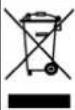
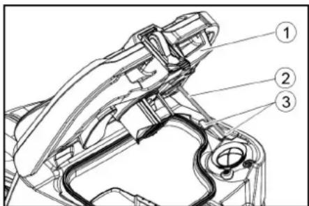
Description of the unit
Overview of the device
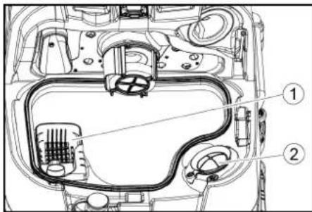
①* Filling system
②Fresh water tank cap with fresh water filter
③Coarse dirt filter
④ Waste water tank cap
⑤Control panel
⑥Squeegee blade adjustment wheel (D cleaning head only)
⑦Brush replacement pedal (D cleaning head only)
⑧ Steering wheel
⑨Squeegee blade
⑩ Brush replacement handle (R cleaning head only)
⑪ Sidelight
⑫Coarse dirt container (only with R cleaning head)
⑬Detergent canister
⑭Type plate
⑮Detergent suction hose
⑯Battery
17* Internal charger
⑱Battery connector (with external charger) Charger mains cable (with internal charger)
⑲Storage area for "Homebase Box" cleaning set
20* Warning light
21Seat
②2 Waste water tank latch
23 Seat adjustment lever
⑳Fresh water tank filling hole
25 Hose holder
②6Daytime running light
27 Accelerator pedal
28* Side scrubbing deck
29* Water connection for dirty water tank rinsing system
30 Waste water tank lid support
③1Float
32Fluff filter
③3 Storage for suction bar
③4 Waste water tank drain hose with dosing unit
③5 Waste water tank
36* Mop holder
37 Suction hose
38 Suction bar clamping lever
39 Waste water tank cap
40 Suction bar
④1Cleaning head
④2Fresh water filling level indicator
④3Fresh water tank
* optional
Colour coding
- Control elements for the cleaning process are yellow.
- Control elements for maintenance and servicing are light grey.
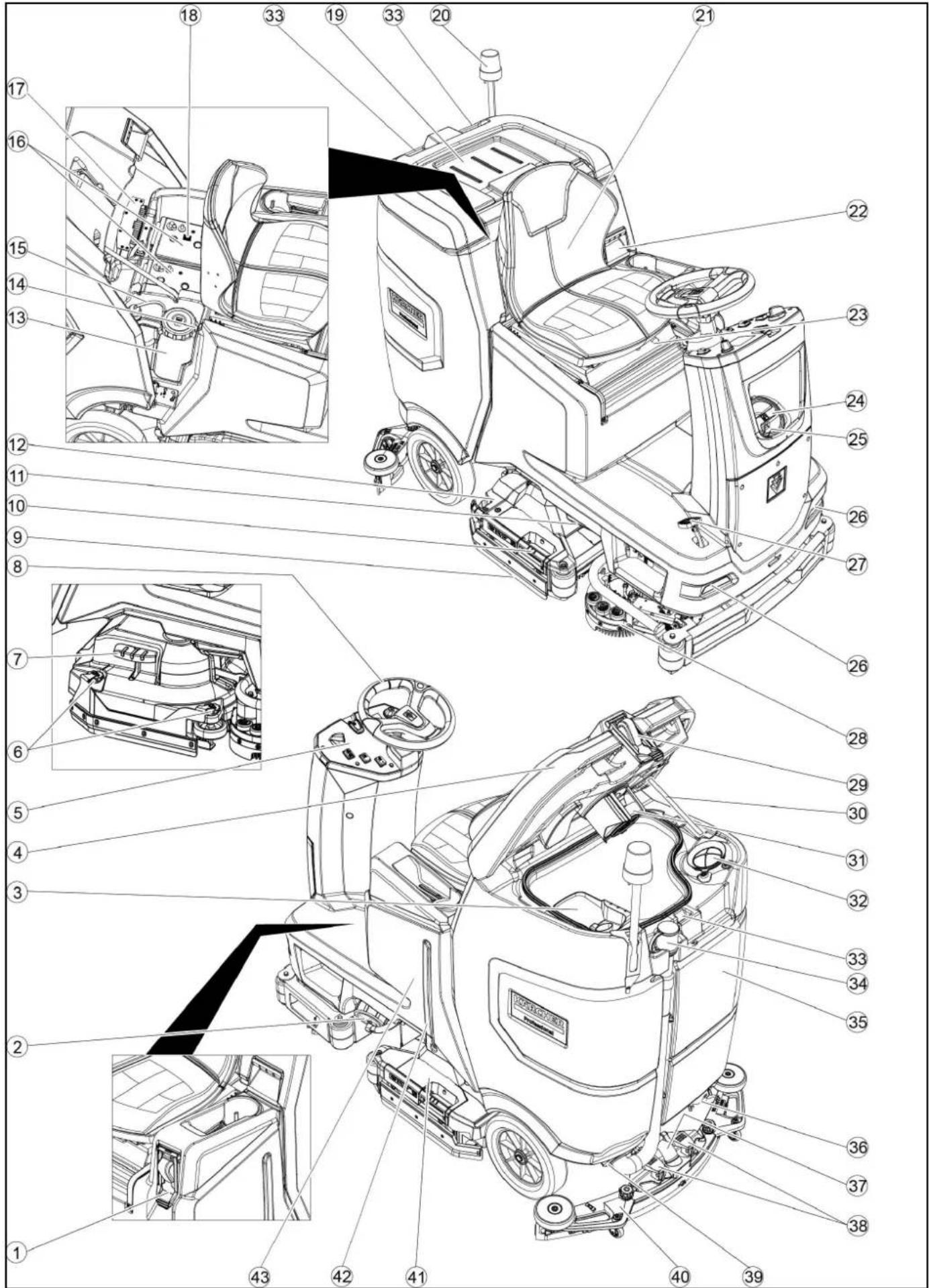
Control panel

①* Side scrubbing deck switch
②Horn
③Travel direction switch
④Program switch
⑤Intelligent Key
⑥Display
⑦Info button
⑧Safety switch
Program switch
①OFF
Device is switched off.
②TRANSPORT MODE
Drive to the operating location.
③ ECO MODE
Clean the floor wet (with a reduced amount of water and a reduced brush speed) and vacuum up waste water (with reduced suction power).
4 NORMAL MODE
Clean the floor wet and vacuum up waste water.
⑤HEAVY MODE
Clean the floor wet (with increased brush contact pressure) and vacuum up waste water.
⑥SCRUB MODE
Precleaning without vacuuming Clean the floor wet and let the detergent act.
⑦SUCTION MODE
Vacuum up the dirty waste.
⑧POLISH MODE
Polish the floor at a high brush speed without applying liquid.
Suction bar holder
- When driving through narrow spaces, the suction bar can be removed and hung in one of the openings on the lid of the waste water tank.
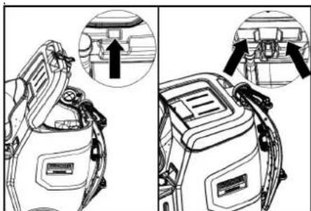
natural_image
Technical line drawing of a vehicle battery pack with two views showing internal components (no text or symbols)The suction bar can be hung in the recess on the waste water tank for storage.
Symbols on the device

Fresh water tank drain opening

Waste water tank drain opening

Fresh water tank filling level (50%)

Lashing point

* Mop holder

Filling system water connection

Waste water tank flushing system water connection

Brush replacement
* optional
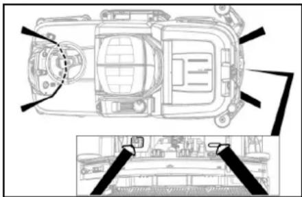
Installation
Unloading
-
Remove the packaging film.
-
Remove the strap.
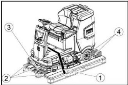
①Strap
②Board
③Block
④Beam
-
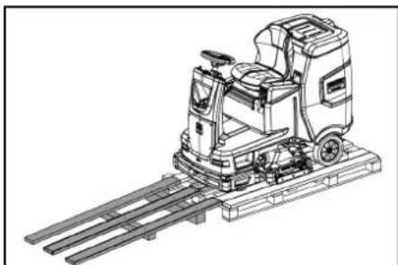
Unscrew the block, squared timber and boards. The components to be unscrewed are marked in grey in the figure.
-
Place a ramp in front of the pallet with the unscrewed boards and squared timber and fasten with chipboard screws.
natural_image
Technical line drawing of a mechanical cleaning or inspection machine on a platform (no text or symbols visible)-
Install the batteries if the device was delivered without batteries (see chapter "Before initial startup/ batteries").
-
Drive the device forward and off the pallet (see chapter "Operation / Driving").
Installing he brushes
- The installation of the brushes is described in the chapter "Maintenance work".
Installing the suction bar
- Pivot both clamping levers upwards.
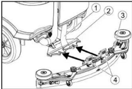
①Suction hose
②Suction bar suspension
③Suction bar
④Clamping lever
2. Insert the suction bar in the suction bar mount.
3. Pivot both clamping levers downwards.
Batteries
Recommended battery sets
| Descrip-tion | Order no. | Volume (m3)* | Airflow (m3/h)** |
| 170 Ah - Maintenance-free, AGM | 4.039-352.7 | 2.4 1.0 | |
| 180 Ah - Maintenance-free, gel | 4.039-354.7 | 3.8 1.6 | |
| 285Ah - Maintenance-free, AGM | 4.039-353.7 | 12.6 5.1 |
* Minimum volume of the battery charging room
** Minimum airflow between battery charging room and environment
Installing and connecting batteries
△CAUTION
Removing and installing the batteries
Unstable machine position
Ensure that the machine is positioned stably when removing and installing the batteries.
ATTENTION
Incorrect connection polarity
Destruction of the control electronics Take care to ensure the correct polarity when connecting the batteries.
ATTENTION
Deep discharge
Risk of damage
Charge the batteries before starting the device.
- Drain the waste water.
- Unlock the waste water tank and pivot it up.
- Place the battery in the device.
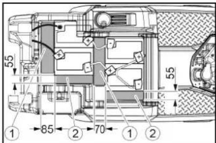
170 Ah, 4.039-352.7
①Spacer 310x85x70 mm
②Spacer 240x55x30 mm
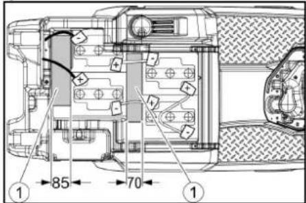
180 Ah, 4.039-354.7
①Spacer 310x85x70 mm
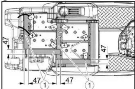
285 Ah, 4.039-353.7
①Spacer 345x60x47
- Insert the spacers at the locations shown in the picture between the battery and the device.
- Connect the battery terminals using the connection cables provided.
- Clamp the connecting cables on the (+) and (-) battery terminals that are still free.
Note
For the 170 Ah 4.039-352.7 battery set, attach the connection cable to the negative pole with the insulated pole screw.
- Connect the device-side battery connector to the battery-side battery connector.
- Pivot the waste water tank forwards and close it.
Removing the battery
△CAUTION
Removing and installing the batteries
Unstable machine position
Ensure that the machine is positioned stably when removing and installing the batteries.
- Set the safety switch to "0".
- Drain the waste water.
- Unlock the waste water tank and pivot it up.
- Pull out the battery plug.
-
Disconnect the cable from the minus terminal at the battery.
-
Disconnect the remaining cables from the battery.
- Remove the battery.
- Dispose of the used batteries in accordance with statutory provisions.
Initial startup
Charging the battery
△DANGER
Inappropriate use of the charger
Electric shock
Adhere to the mains voltage and fuse values specified on the device type plate.
Only use the charger in dry rooms with sufficient ventilation.
Flammable gases are generated when the battery is charged
Risk of explosion
Only charge the battery in a suitable room. The room must have a minimum volume depending on the battery type and an adequate air exchange rate with a minimum air flow (see "Recommended batteries").
ATTENTION
Accumulation of dangerous gases under the tank during the charging process
Risk of explosion
Pivot the waste water tank upwards before charging low-maintenance batteries.
The average charging time is approx. 10-15 hours.
The device cannot be used during the charging process.
Note
The device has deep discharge protection, i.e. the brush motor and turbine are switched off automatically when the permitted minimum capacity level is reached.
- Drive the device directly to the charger and do not drive on slopes.
External charger
ATTENTION
Using an unsuitable charger
Risk of damage
Do not connect the charger to the device-side battery connector.
Use only a charger suitable for the type of battery installed.
Read the operating instructions of the charger manufacturer and observe the safety instructions in particular.
| Battery Capacity Charger | |
| 4.039-352.7 170 | Ah 6.654-436.0 |
| 4.039-354.7 180 | Ah 6.654-434.0 |
| 4.039-353.7 285 | Ah 6.654-419.0 |
- Unlock the waste water tank and pivot it up.
- Pull out the device-side battery connector.
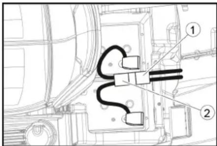
①Battery plug, device side
②Battery plug, battery side
3. Connect the battery-side battery connector to the charger.
4. Plug the mains plug of the charger into the socket.
5. Carry out the charging process in accordance with the operating instructions for the charger.
6. Connect the device-side battery connector to the battery-side battery connector.
7. Pivot the waste water tank forwards and close it.
Internal charger
- Unlock the waste water tank and pivot it up.
- Plug the mains plug of the internal charger into the mains socket. The charging state of the battery is shown on the control panel display.
- Unplug the charger mains plug from the mains socket after charging.
- Pivot the waste water tank forwards.
Low-maintenance batteries (wet batteries)
△DANGER
Refilling discharged batteries with water
Danger of acid burns from escaping acid, destruction of clothing
Wear safety goggles, protective clothing and protective gloves when handling the battery acid.
Observe the applicable regulations. Immediately rinse off any splashed acid from the skin or clothing using copious amounts of water.
ATTENTION
Using water with additives
Defective batteries, loss of warranty eligibility
Top up the batteries using only distilled or desalinated water (EN 50272-T3).
Do not use any foreign additives, so-called enhancing agents, because this will invalidate the warranty.
- Add distilled water one hour before the charging process comes to an end. Observe the correct acid level according to the battery label. All cells must produce gas at the end of the charging process.
- Clean up any spilled water. To do this, proceed as described in the Care and maintenance chapter in the "Cleaning the batteries" section.
Operation
△DANGER
Falling objects
Risk of injury
Do not drive the device into areas where there is a possibility of the operating personnel being hit by falling objects.
ATTENTION
Risks during operation
Risk of injury
In the event of danger, set the safety switch to "0".
Pushing the device
To push the device, the brake must be unlocked.
△DANGER
Danger of accident
When the brake is unlocked, the function of the brake is permanently out of operation. Be sure to remove the coins for unlocking immediately after the sliding process has ended.
- Swing the unlocking lever away from the wheel and hold it there.
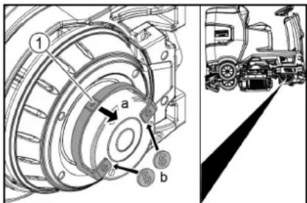
① Unlocking lever
- Insert a coin between the casing and the lever at both ends of the lever.
- Release the unlocking lever.
- Push the device.
- Remove both coins immediately after pushing.
Adjusting the seat
Adjusting the height
- Stand next to the device.
- Raise the seat at the back.
- Align the front seat bracket to the desired height of the device.
- Lower the seat at the back.
Adjusting the position
- Operate the seat adjustment lever and move the seat to the desired position.
- Release the seat adjustment lever and latch the seat into position.
Switching the device on
- Sit in the driver's seat.
- Insert the Intelligent Key.
- Set the safety switch to "1".
- Turn the program switch to the desired function.
- If one of the displays below appears on the display, take your foot off the accelerator pedal, set the safety switch to "0" and carry out the necessary maintenance work.
| Display Activity | |
| maintenance squeegee | Clean the suction bar. |
| maintenance brush head | Check the brushes for wear and clean them. |
| maintenance squeegee blade | Check the suction lips for wear and correct adjustment. |
| maintenance turbine filter | Clean the fluff filter. |
| maintenance fresh water filter | Clean the fresh water filter. |
- Press the Info button.
- Reset the counter for the corresponding maintenance (see "Grey Intelligent Key / Reset maintenance counter").
Note
If the counter is not reset, the maintenance display appears again each time the device is switched on.
Switching on the light
Daytime running light
The daytime running light is in operation when the device is switched on.
Sidelight
The sidelight lights up as soon as the program switch is set to a cleaning program.
Checking the parking brake
△DANGER
Defective parking brake
Danger of accident
Before each operation, check the function of the parking brake on level ground.
- Switch the device on.
- Set the travel direction switch to "Forward".
- Set the program selector switch to "TRANSPORT MODE".
- Press the accelerator pedal lightly. The brake must audibly unlock. The appliance must roll easily on a plane surface.
- Release the accelerator pedal. The brake must be audibly engage.
If this is not the case, take the device out of operation and call Customer Service.
Driving
△DANGER
Lack of braking
Danger of accident
Before using the device, it is essential to check the function of the parking brake.
Never use the device if the parking brake does not work.
△DANGER
Careless driving
Danger of tipping over
Only drive up and up gradients in the direction of travel and across the direction of travel 10%.
Do not turn up or down gradients.
Drive slowly in corners and on wet ground.
Only drive the device on stable ground.
Note
The travel direction can be changed while driving. This means that very dull spots can be polished by moving back and forth several times.
- Assume a seated position.
- Insert the Intelligent Key.
- Turn the safety switch to "1".
- Set the program selector switch to "TRANSPORT MODE".
- Set the direction of travel using the drive direction button on the control panel.
-
Specify the travel speed by pressing the accelerator pedal.
-
Release the accelerator pedal. The device stops.
The driving motor is switched off in the event of an overload. A fault message appears on the display. If the controller overheats, the affected power unit is switched off.
-
Allow the device to cool down for at least 15 minutes.
-
Set the program switch to "OFF", wait briefly and set to the desired program.
Filling with fresh water
Filling with fresh water via the filling system
-
Connect the water hose to the connection nozzle of the filling system (maximum water temperature 50 °C).
-
Open the water inlet.
-
Monitor the device, the automatic filling system interrupts the water supply when the fresh water tank is full.
-
Close the water inlet.
-
Remove the water hose.
Filling with fresh water
- Open the fresh water tank cap.
- Fill fresh water (max. 50 °C) to the lower edge of the filling nozzle.
Note: The fresh water hose can be clamped with the hose holder during filling. - Close the fresh water tank lock.
Filling with detergent
Notes on detergents
△WARNING
Unsuitable detergents
Health risk, damage to the device Use only recommended detergents. The operator carries all increased risks relating to operational safety and increased risk of accidents if using other detergents. Use only detergents free of chlorine, solvents, salt and hydrofluoric acid. Adhere to the safety instructions stated on the detergent packaging.
Note
Do not use heavily foaming detergent.
Recommended detergents
| Application Detergent | |
| Maintenance cleaning of all water-resistant floors | RM 746RM 756RM 780 |
| Maintenance cleaning of polished hard surfaces (e.g. granite) | RM 755 es |
| Maintenance cleaning, intermediate cleaning and basic cleaning of industrial floors | RM 69 ASF |
| Maintenance cleaning and basic cleaning of fine stone tiles | RM 753 |
| Maintenance cleaning of tiles in sanitary areas | RM 751 |
| Coating removal on all alka-line-resistant floors (e.g. PVC) | RM 752 |
| Coating removal on linole-um floors | RM 754 |
Filling detergent via the dosing device Only with DOSE variant:
Detergent is added to the fresh water on the way to the cleaning head by a dosing device.
- Unlock the waste water tank and pivot it up.
- Fill the detergent canister with detergent.
- Pivot the waste water tank forwards.
Note
A maximum of 3% detergent can be added with the dosing device. If the dosage is higher, the detergent must be added to the fresh water tank.
Filling the detergent into the fresh water tank
- Fill the detergent into the fresh water tank. Note: The lid for the filling hole of the fresh water tank can be used to measure the detergent. It has a measuring scale marked on the inner side.
Adjusting parameters
- Set the program switch to the desired cleaning program.
- Turn the Info button until the desired parameter is displayed.
- Press the Info button. The adjusted value flashes.
- Set the desired value by turning the Info button.
- Confirm the changed setting by pressing the Info button or wait until the set value is automatically accepted after 10 seconds.
Yellow Intelligent Key
The yellow Intelligent Key authorizes functions that are required for the cleaning task. The parameters for the various cleaning programs are preset in the device. Individual parameters can be changed depending on the authorization of the yellow Intelligent Key. The display texts for parameter setting are largely self-explanatory.
"FACT" parameters (only available with R cleaning head):
- "Fine Clean": Low brush speed for removing grey film from fine stone.
- "Whisper Clean": Medium brush speed for maintenance cleaning with reduced noise level.
- "Power Clean": High brush speed for polishing, crystallizing and sweeping.
Adjusting the suction bar
Adjusting the inclination
The inclination must be adjusted so that the suction lips of the suction bar make even contact with the floor over the entire length of the suction bar.
- Park the device on a surface without a slope.
- Turn the program switch to the "Vacuum" position.
- Drive the device a small distance forwards.
- Read the spirit level.
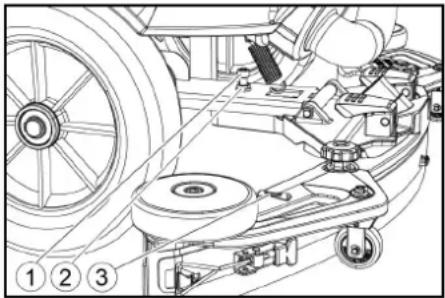
natural_image
Technical line drawing of a mechanical assembly with pulleys, gears, and components (no text or symbols)① Screw
②Nut
③Spirit level
-
Unscrew the nut.
-
Adjust the screw so that the spirit level indicator is between the two lines.
-
Tighten the nut.
-
To check the new setting, move the device forward again a short distance. Repeat the adjustment process if necessary.
-
Turn the key-operated switch to "OFF".
Adjusting the height
The height adjustment affects the bending of the suction lips on contact with the floor.
Note
Standard setting: 3 washers above, 3 washers below the suction bar.
Uneven floor: 5 washers above, 1 washer below the suction bar.
Very smooth floor: 1 washer above, 5 washers below the suction bar.
- Unscrew the nuts.
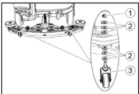
①Nut
② Washer
③ Spacer roller with holder
- Place the desired number of washers between the suction bar and the spacer roller.
- Fit the remaining unused washers above the spacer roller.
- Screw on the nut and tighten.
- Repeat the entire procedure at the second spacer roller.
Note
Set both spacer rollers to the same height.
Adjusting the squeegee blades
The squeegee blades only need to be adjusted on the D cleaning head.
-
Adjust the squeegee blades by turning the setting wheel so that the squeegee blade touches the ground.
-
Turn the adjustment wheel an additional 1 rotation down.
Cleaning
- Sit on the seat.
- Insert the Intelligent Key.
- Set the safety switch to "1".
- Set the travel direction switch to forward travel.
- Set the program switch to the desired cleaning program.
- Determine the speed with the accelerator pedal.
- Determine the travel direction with the steering wheel.
- Drive over the surface to be cleaned.
Side scrubbing deck (option)
The side scrubbing deck makes working close to the edge easier.
Note
The side scrubbing deck is not active in the polish and vacuum cleaning programmes.
-
Operate the side scrubbing deck switch. The side scrubbing deck is activated.
-
To finish working with the side scrubbing deck, set the side scrubbing deck switch to "0".
Finishing operation
Finishing cleaning
- Set the programme switch to Drive.
- Continue moving a short distance. The residual water is vacuumed up.
- Turn the key-operated switch to "OFF".
- Remove the Intelligent Key.
- Charge the battery if necessary.
Draining the waste water
⚠ WARNING
Improper disposal of waste water
Environmental pollution
Observe the local waste water treatment regulations.
Note
When the waste water tank is full, the suction flow is interrupted by a float to prevent the waste water tank from overflowing. In this case, drain the waste water.
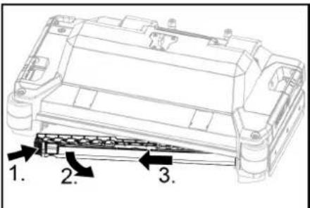
- Remove the waste water drain hose from the support and open the drain hose cover.
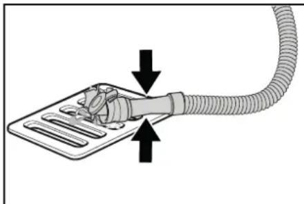
natural_image
Diagram showing a hand holding a flexible hose connected to a device with directional arrows indicating movement (no text or symbols)- Squeeze the end of the hose and lower it over the disposal facility.
- Adjust the strength of the waste water jet by squeezing the end of the hose.
- Rinse the waste water tank with clear water.
- Close the drain hose cover.
- Press the waste water hose into the support on the device.
Waste water tank rinsing system (option)
- Remove the waste water drain hose from the support and open the drain hose cover.
- Close the cover of the waste water tank.
- Connect a water supply hose to the water connection of the waste water tank flushing system.
- Open the water inlet and rinse the waste water tank for about 30 seconds.
- Repeat the rinsing process 2 to 3 times if necessary.
- Close the water inlet.
- Disconnect the water supply hose from the device.
- Close the waste water drain hose and press it into the support.
Empty the coarse dirt container
- Lift the coarse dirt container and pull it out.
- Empty the coarse dirt container.
- Reinstall the coarse dirt container.
Draining fresh water
- Open the fresh water tank cap.
- Drain the fresh water.
- Clean the filter.
- Fit the fresh water tank cap.
Shutting down the unit
- Turn the key-operated switch to "OFF".
- Remove the Intelligent Key.
- Secure the device against rolling away.
- Open the lid of the waste water tank and secure it with the support so that the waste water tank can dry out. To do this, swing the support down and position the lower end at the desired level when swinging down the cover.
① Waste water tank cap
②Support
③level
- Charge the battery if necessary.
Grey Intelligent Key
The grey Intelligent Key grants the supervisory staff extended authorizations and setting options.
- Insert the Intelligent Key.
- Select the desired function by turning the info button.
Transport journey
- Set the program selector switch to "TRANSPORT MODE".
- Press the Info button.
The following functions can be executed from the TRANSPORT MODE menu: - Set maximum speed
• Show operating hours counter - Clearing the maintenance counter
• Show software versions - Adjust the R or D cleaning head
- Switch speed-dependent water dosage on / off
- Setting after-running times
- Setting the language
• Key management - Switch attachment kits on / off
• Activate factory setting
Maximum speed
The maximum speed can be limited in the "max speed" menu.
- Turn the info button until "max speed" is shown on the display.
- Press the Info button.
- Turn the info button until the desired maximum speed is displayed.
- Press the Info button.
Note
The working speed cannot exceed the maximum speed set.
Resetting the maintenance counter
If maintenance work shown in the display has been carried out, the corresponding maintenance counter must then be reset.
- Turn the Info button until "maintenance count." is displayed.
- Press the Info button.
The counter readings are displayed. - Turn the info button until the counter to be cleared is highlighted.
- Press the Info button.
- Select "yes" by turning the Info button.
- Press the Info button.
The counter is cleared.
Adjusting the cleaning head
- Turn the Info button until "brush head" is displayed in the menu.
- Press the Info button.
- Turn the info button until the type of the built-in cleaning head is highlighted.
"Roll" = R cleaning head
"Disc" = D cleaning head - Press the Info button.
Speed-dependent water dosing
If the speed-dependent water dosing is switched on, the brush irrigation changes proportionally with the speed.
The water dosing is also influenced by the setting of the respective cleaning program (0 ... 100%).
| Setting ON [ml/m 2] OFF[l/min] | ||
| 0% 0 0 | ||
| 10% 7.5 0.6 | ||
| 20% 15 | 1.1 | |
| 30% 22.5 | 1.7 | |
| 40% 30 | 2.3 | |
| 50% 37.5 | 2.8 | |
| 60% 45 | 3.4 | |
| 70% 52.5 | 3.9 | |
| 80% 60 | 4.5 | |
| 90% 67.5 | 5.1 | |
| 100% | 75 | 5.7 |
Set speed-dependent or constant water dosing:
- Turn the Info button until "water dosage mode" is shown on the display.
- Press the Info button.
- Turn the info button until the desired function is highlighted.
- Press the Info button.
After-running time
- Turn the info button until the "delay times" menu item appears on the display.
- Press the Info button.
- Turn the info button until the desired assembly is highlighted.
- Press the Info button.
- Turn the info button until the desired after-running time is displayed.
- Press the Info button.
Setting the language
- Turn the info button until the "language" menu item appears on the display.
- Press the Info button.
- Turn the info button until the desired language is highlighted.
- Press the Info button.
Key management
The menu item "key menu" enables authorizations for yellow Intelligent Keys and the language of the display.
- Insert the grey Intelligent Key.
- Turn the info button until the "key menu" menu item appears on the display.
- Press the Info button.
- Remove the grey Intelligent Key and insert the yellow Intelligent Key to be personalized.
- Select the menu item to be changed by turning the info button.
- Press the Info button.
- Select the setting of the menu item by turning the info button.
- Confirm the setting by pressing the menu item.
-
Select the next menu item to be changed by turning the info button.
-
After all settings have been made, call up the "save" menu by turning the info button.
- Press the Info button.
The authorizations are saved.
Switch attachment kits on / off
- Turn the info button until the desired attachment kit is shown on the display.
- Press the Info button.
- Turn the info button until the desired function of the attachment kit is displayed.
- Press the Info button.
Factory setting
The factory settings for all cleaning parameters are restored.
- Turn the info button until the "factory settings" menu item is displayed.
- Press the Info button.
- Turn the Info button until "yes" is highlighted.
- Press the Info button.
Adjusting parameters for cleaning programs
All parameters for cleaning programs are retained until another setting is selected.
- Set the program switch to the desired cleaning program.
- Press the Info button.
The first adjustable parameter is displayed.
- Press the Info button
The adjusted value flashes. - Set the desired value by turning the Info button.
- Confirm the changed setting by pressing the Info button or wait until the set value is automatically accepted after 10 seconds.
- Select the next parameter by turning the Info button.
- After changing all desired parameters, turn the Info button until the "exit" menu item is displayed.
- Press the Info button.
The menu is exited.
Transport
△DANGER
Driving on slopes
Risk of injury
Observe the maximum permissible gradient when driving the device on slopes for loading and unloading purposes (see chapter "Technical data").
Drive slowly.
△CAUTION
Failure to observe the weight
Risk of injury and damage
Be aware of the weight of the device during transportation.
- With the D cleaning head installed, remove the disc brushes from the brush head.
- When transporting in vehicles, secure the device against slipping and tipping over according to the applicable guidelines.
Storage
△CAUTION
Failure to observe the weight
Risk of injury and damage
Be aware of the weight of the device during storage.
ATTENTION
Frost
Destruction of the device through freezing water Drain all water from the device.
Store the device in a frost-free location.
• This device may only be stored indoors.
- Fully charge the batteries before storing them for a long period.
- Fully charge the batteries at least every month during storage.
Care and maintenance
△DANGER
Inadvertently starting up device
Risk of injury, electric shock
Turn the program switch to the "OFF" position.
Remove the Intelligent Key prior to all work on the device.
Pull out the charger mains plug.
Unplug the battery connector.
- Drain and dispose of the waste water and fresh water.
Maintenance intervals
Each time after use
ATTENTION
Improper cleaning
Risk of damage.
Do not spray the device with water.
Do not use aggressive cleaning agents.
A detailed description of the individual maintenance work is provided in the chapter "Maintenance Work".
- Drain the waste water.
● Rinse the waste water tank with clear water.
● Clean the coarse dirt filter. - Only with R cleaning head: Remove the coarse dirt container and empty it.
- Clean the exterior of the device using a damp cloth, wetted with a mild washing lye.
- Check the suction lips, check for wear and replace if necessary.
- Clean the squeegee blades, check for wear and replace if necessary.
- Clean the brushes, check for wear and replace if necessary.
- Charge the battery.
- If the charging state of the battery is below 50%, charge the battery fully and without interruption.
- If the charging state of the battery is above 50%, only recharge the battery if the entire operating duration will be required when next used.
Weekly
- When used regularly, charge the battery fully and without interruption at least once a week.
Monthly
A detailed description of the individual maintenance work is provided in the chapter "Maintenance Work".
- If the device is temporarily shut down: Perform equalization charging of the battery.
- Check battery poles for oxidation, brush off if necessary. Make sure the connection cables are firmly in place.
- Clean the seals between the waste water tank and the cover, check for leaks and replace if necessary.
- Drain the fresh water tank and flush out deposits.
- Clean the fresh water filter.
- Check the acid density of the cells if the batteries are not maintenance-free.
- Only with R cleaning head: Clean the brush tunnel.
- Only with R cleaning head: Clean the water distribution strip on the cleaning head.
- For longer periods of disuse, shut down the device when the battery is fully charged. Fully charge the battery at least once a month.
Annually
● Have the prescribed inspection performed by Customer Service.
Safety inspection/maintenance contract
You can agree on regular safety inspections or close a maintenance contract with your dealer. Please seek advice on this.
Maintenance work
Turn over or replace the worn suction lips
The suction lips must be turned over or replaced when worn out.
The suction lips can be turned 3 times until all 4 edges are worn.
- Remove the suction bar.
- Unscrew the star handles.
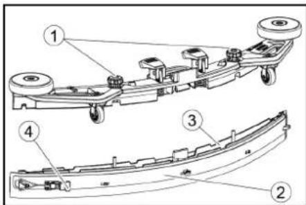
①Star grip
②Strap
③Inner part of the suction bar
④Tension lock
3. Pull out the inner part of the suction bar.
4. Open the tension lock.
5. Remove the strap.
6. Release the suction lips from the inner part.
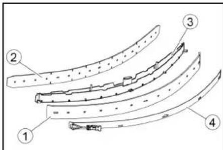
①Squeegee blade
②Support lip
③Inner part of the suction bar
④Strap
- Press the turned or new suction lips onto the knobs of the inner part of the suction bar.
- Attach the strap.
- Push the inner part of the suction bar into the upper part.
- Screw in and tighten the star handles.
Cleaning the coarse dirt filter
- Open the waste water tank cover.
①Coarse dirt filter
②Fluff filter
2. Pull the coarse dirt filter upwards and off.
3. Rinse off the coarse dirt filter under running water.
4. Reinsert the coarse dirt filter into the waste water tank.
Cleaning the float and fluff filter
- Open the waste water tank cover.
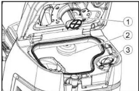
①Float
②Float switch
③Fluff filter
2. Rinse the float with clear water.
3. Rinse the float switch with clear water.
4. Remove and clean the fluff filter.
Replacing the disc brush
Note
Replace the disc brushes when the bristle length has reached 10 mm.
- Raise the cleaning head.
- Push the brush replacement pedal down.
- Pull the disc brush sideways and out from underneath the cleaning head.
- Hold the new disc brush under the cleaning head, then press upwards and latch it into position.
Replacing the roller brushes
Note
Replace the roller brushes when the bristle length has reached 10 mm.
- Raise the cleaning head.
- Pull out the brush replacement handle.
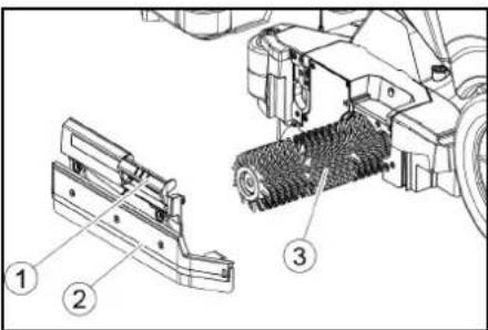
①Brush replacement handle
② Bearing cover with squeegee blade
③Roller brush
3. Remove the bearing cover including the squeegee blade.
4. Pull out the roller brush.
5. Fit the new roller brush and centre it on the driver.
①Driver
②Mounting mandrel
6. Install the bearing cover with the squee-gee blade.
Note
Make sure the roller brush sits on the mounting mandrel and not underneath
- Pivot the brush replacement handle upwards and latch it into place.
- Repeat the entire procedure at the other side.
Replacing the side scrubbing deck brush (option)
- Press the brush replacement lever downwards.

①Side scrubbing deck brush
②Brush replacement lever
The brush falls out of the support.
- Hold the new brush under the side scrubbing deck, then press upwards and latch it into position
Cleaning the fresh water filter
- Drain the fresh water (see chapter "Draining fresh water").
- Unscrew the fresh water tank cap.
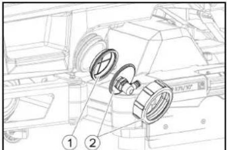
①Fresh water filter
②Fresh water tank lock
3. Pull out the fresh water filter and rinse with clean water.
4. Insert the fresh water filter.
5. Fit the fresh water tank lock.
Note: Take care to ensure that the hose connection in the fresh water tank cap is positioned at the lowest point in the tank after screwing the cap in place.
Cleaning the water distribution strip
- Press the latch in the direction of the arrow and hold it there.
- Pivot the water distribution strip forward.
- Pull out the water distribution strip lengthways.
- Clean the water distribution strip.
- Fit the water distribution strip back into the cleaning head and snap the lock into place.
Cleaning batteries
- Wear safety goggles, protective clothing and protective gloves.
- Keep the battery cell plugs closed.
- Remove the batteries.
- Only clean the plastic parts of the batteries and the battery compartment with water or water-soaked cleaning cloths without additives.
- Dry the surfaces after cleaning.
- Reinstall the batteries.
Resetting the maintenance counter
If maintenance work shown in the display has been carried out, the corresponding maintenance counter must then be reset.
Note
Resetting the maintenance counters is described in the chapter "Grey Intelligent Key".
Troubleshooting guide
△DANGER
The device can start unintentionally
People working on the device can be injured. Remove the Intelligent Key prior to all work on the device.
Before carrying out any work, pull the mains plug of the internal charger out of the socket.
Disconnect the battery connector before performing any work.
-
Drain the waste water.
-
Drain the remaining fresh water.
Note
If the malfunction cannot be remedied with the following instructions, contact Customer Service.
Malfunctions with information shown on the display
If the displayed malfunction is not in the following list, do the following:
- Turn the key-operated switch to "OFF".
- Wait 10 seconds.
- Set the program switch to the previous function.
- If the malfunction recurs, call Customer Service.
| Malfunction Rectification | |
| fresh water empty 1. Refill the | fresh water tank |
| water valve blocked 1. Set the | programme switch to "OFF".2. Wait 10 seconds.3. Set the program switch to the desired program. |
| overload brush head 1. Reduce | the contact pressure of the brushes. |
| blocked main brush | 1. Check if the brushes are blocked by a foreign body and remove the foreign body if necessary.2. Set the programme switch to "OFF".3. Wait 10 seconds.4. Set the program switch to the desired program. |
| overload side brush 1. Reduce | the contact pressure of the side scrubbing deck brush. |
| blocked side brush | 1. Check if the brushes are blocked by a foreign body and remove the foreign body if necessary.2. Set the programme switch to "OFF".3. Wait 10 seconds.4. Set the program switch to the desired program. |
| waste water tank full 1. Empty | the waste water tank. |
| overload drive motor 1. The gradient is too steep.a In cleaning operation: Cancel cleaning.b When transporting: Find a path with a lower gradient. | |
| blocked drive motor 1. Check | the wheels for blockage, remove foreign objects.2. Set the programme switch to "OFF".3. If the engine has overheated, let it cool down for at least 15 minutes, otherwise wait 10 seconds.4. Set the program switch to the desired program. |
| battery low | 1. Set the program selector switch to TRANSPORT MODE.2. Drive the device directly to the charger (or with an internal charger to the socket). Avoid gradients.3. Charge the battery. |
| battery empty | 1. Set the program selector switch to TRANSPORT MODE.2. Drive the device by the shortest route to the charger (or to the socket in the case of an internal charger). Avoid gradients.3. Charge the battery. |
| seat switch open | 1. Relieve the driver's seat briefly so that the control can check the function of the seat contact switch. |
| switch on! | 1. Set the safety switch to "1". |
| Malfunction Rectification | |
| restart machine 1. Set the programme switch to "OFF".2. Wait 10 seconds.3. Set the program switch to the desired program. | |
| release throttle 1. Release the accelerator pedal. | |
Malfunctions without information shown on the display
| Malfunction Rectification | |
| The device cannot be started | 1. Sit in the driver's seat.2. Take your foot off the accelerator before switching on the safety switch.3. Turn the safety switch to "1".4. Check the battery and charge if necessary.5. Set the programme switch to "OFF".6. Wait 10 seconds.7. Set the program switch to the desired program.8. If possible, only drive the device on level ground.9. Check the parking brake if necessary.If the fault still occurs, call Customer Service. |
| The device is no longer running, display shows "battery empty" | 1. Set the programme switch to "OFF".2. Wait 10 seconds.3. Set the program selector switch to "TRANSPORT MODE".4. Drive to the charging station.5. If the device still does not run, charge the battery on site or unlock the brake (see "Operation/pushing the device") and push the device to the charging station. |
| The device moves unevenly (jerks) when starting and stopping. | 1. Unlock the brake lock (see "Operation/pushing the device"). |
| The water volume is insufficient | 1. Check the fresh water filling level, if necessary fill the tank completely so that the air is pressed out.2. Remove and clean the fresh water filter.3. Insert the filter and screw on the cap.4. Only with R cleaning head: Pull off the water distribution strip on the cleaning head.5. Only with R cleaning head: Clean the water channel.6. Check the hoses for clogging and clean if necessary. |
| The fresh water display shows the wrong filling level after emptying the tank manually. | 1. Use the device. During operation, the hose system will vent and the filling level display will correct itself. |
| The bar of the filling level display is flashing, "fresh water empty" display | 1. Refill the fresh water tank. |
| The suction performance is too low | 1. Clean the seals between the waste water tank and the cover, check for leaks and replace if necessary.2. Check the fluff filter for soiling and clean if necessary.3. Clean the suction lips at the suction bar, turn over or replace if necessary.4. Close the lid on the waste water drain hose.5. Close the cover of the waste water tank rinsing system.6. Check the suction hose for clogging and clean if necessary.7. Check the suction hose for leaks and replace if necessary.8. Check the adjustment of the suction bar. |
| The cleaning results are unsatisfactory | 1. Set the appropriate cleaning program for the cleaning task.2. Use suitable brushes for the cleaning task.3. Use a suitable detergent for the cleaning task.4. Reduce the driving speed.5. Adjust the contact pressure.6. Adjust the squeegee blades.7. Check the brushes for wear and replace if necessary.8. Check the water output. |
| The brushes do not rotate 1. | Reduce the contact pressure.2. Check if the brushes are blocked by a foreign body and remove the foreign body if necessary.3. If the motor is overloaded, let the motor cool down.4. Set the programme switch to "OFF".5. Wait 10 seconds.6. Set the program switch to the desired program.7. Check that the plug of the device is plugged into the cleaning head. |
| The device does not brake | 1. Undo the brake lock (see "Operation / Pushing the device"). |
| The waste water drain hose is clogged | 1. Open the dosing unit cover at the drain hose.2. Pull the suction hose off the suction bar and close it by hand.3. Set the programme switch to "Vacuum".The blockage is sucked out of the drain hose into the waste water tank. |
| The "Dose" detergent dosing unit does not work | 1. "Dose" version only: Call Customer Service. |
Warranty
The warranty conditions issued by our relevant sales company apply in all countries. We shall remedy possible malfunctions on your appliance within the warranty period free of cost, provided that a material or manufacturing defect is the cause. In a warranty case, please contact your dealer (with the purchase receipt) or the next authorised customer service site. (See overleaf for the address)
Accessories
Cleaning head with roller brush accessories
A: Packaging unit, B: Quantity required by the device
| Description R 65 | Part no. | R 75 Part no. | Description A B | ||
| Roller brush, red (medium, standard) | 4.035-604.0 4 | 035-605.0 For maintenance cleaning of heavily soiled floors. 1 2 | |||
| Roller brush, white (soft) | 6.907-770.0 | 6.907-771.0 | For polishing and maintenance cleaning of sensitive floors. | 1 | 2 |
| Roller brush, orange (high / low) | 6.907-726.0 | 6.907-730.0 | For scrubbing structural floors (safety tiles, etc.). | 1 | 2 |
| Roller brush, green (hard) | 6.907-727.0 | 6.907-731.0 | For basic cleaning of heavily soiled floors and for coating removal (e.g. waxes, acrylates). | 1 | 2 |
| Roller brush, black (very hard) 6.907 | 7-728.0 6.907 | 732.0 1 2 | |||
| Microfiber roller | 4.114-054.0 | 4.114-007.0 | For maintenance cleaning of smooth floors. | 1 | 2 |
| Pad roller shaft | 4.762-626.0 | 4.762-627.0 | For holding roller pads. | 1 | 2 |
| Roller pad, yellow (soft) | 6.369-454.0 | 6.369-454.0 | For polishing floors | 20 | 96; 106 |
| Roller pad, red (medium) | 6.369-456.0 | 6.369-456.0 | For cleaning lightly soiled floors. | 20 | 96; 106 |
| Roller pad, green (hard) | 6.369-455.0 | 6.369-455.0 | For cleaning normal to heavily soiled floors. | 20 | 96; 106 |
Cleaning head with disc brushes accessories
A: Packaging unit, B: Quantity required by the device
| Description D 65 | Part no. | D 75 Part no. | Description | A | B |
| Disc brush, natural colour (soft) | 4.905-012.0 | 4.905-020.0 | For polishing floors. | 1 | 2 |
| Disc brush, white | 4.905-011.0 | 4.905-019.0 | For polishing and maintenance cleaning of sensitive floors. | 1 | 2 |
| Disc brush, red (medium, standard) | 4.905-010.0 | 4.905-018.0 | For cleaning lightly soiled or sensitive floors. | 1 | 2 |
| Disc brush, black (hard) | 4.905-013.0 | 4.905-021.0 | For cleaning heavily soiled floors. | 1 | 2 |
| Fine diamond pad, green | 6.371-235.0 | 6.371-236.0 | For refreshing lime-containing coverings and epoxy resin-coated floors. | 5 | 2 |
| Coarse diamond pad, white | 6.371-250.0 | 6.371-252.0 | 5 | 2 | |
| Medium diamond pad, yellow 6.371 | -251.0 6.371 | -253.0 5 | 2 | ||
| Pad drive board | 4.762-446.0 | 4.762-447.0 | For holding pads. | 1 | 2 |
Suction bar accessories
A: Packaging unit, B: Quantity required by the device
| Description | Part no. | Description | A | B |
| Suction lip set, front PU (red), rear Linatex | 4.039-366.0 | Standard | Pair | 1 pair |
| Suction lip set, Linatex | 4.039-356.0 | Tear-proof | Pair | 1 pair |
| PU suction lip set | 4.039-357.0 | Oil-proof | Pair | 1 pair |
Technical data
| B 110 R 65 B 110 D 65 B 110 R 75 B 110 D 75 | |||||
| General | |||||
| Driving / cleaning speed km/h 6 6 6 6 | |||||
| Transport speed km/h 6 6 6 6 | |||||
| Travel speed, backwards km/h 4 4 4 4 | |||||
| Theoretical surface performance m2/h 3900 3900 4500 4500 | |||||
| Theoretical surface performance with side scrubbing deck | m | 2 | / | h | - |
| Practical surface performance m2/h 2730 2730 3150 3150 | |||||
| Fresh water tank capacity | l | 110 | 110 | 110 | 110 |
| Waste water tank capacity | l | 110 | 110 | 110 | 110 |
| Coarse dirt container capacity | l | 1,6 | - | 1,8 | - |
| Volume of detergent tank ("Dose" option) | l | 5 | 5 | 5 | 5 |
| Detergent dosing | % | 0,25...3 | 0,25...3 | 0,25...3 | 0,25...3 |
| Water dosage | l/min | 0,15...5,7 | 0,15...5,7 | 0,15...5,7 | 0,15...5,7 |
| Load per unit area (with driver and full fresh water tank) | |||||
| Surface pressure | N/mm2 | 0,62...0,66 | 0,62...0,66 | 0,62...0,66 | 0,62...0,66 |
| Load per unit area (weight / parking area) | kg/m2 | 470...542 | 470...542 | 470...542 | 470...542 |
| Dimensions | |||||
| Length | mm | 1640 1640 1640 1640 | |||
| Width | mm | 740 | 740 | 740 | 740 |
| Wide suction bar | mm | 950 | 950 | 950 | 950 |
| Height | mm | 1310 1310 1310 | 1310 | ||
| Working width | mm | 650 | 650 | 750 | 750 |
| Working width with side scrubbing deck | mm | - | - | 850 | 850 |
| Packaging dimensions lxwxh | mm | 1750x990x147 | 1750x990x147 | 1750x990x147 | 1750x990x147 |
| 5 | 5 | 5 | 5 | ||
| Turning circle | mm | 1750 | 1750 | 1750 | 1750 |
| Battery compartment dimensions lxwxh | mm | 2x(315x386x37) | 2x(315x386x37) | 2x(315x386x37) | 2x(315x386x37) |
| 5) | 5) | 5) | 5) | ||
| Tyres | |||||
| Front wheel, width | mm | 90 | 90 | 90 | 90 |
| Front wheel, diameter | mm | 250 | 250 | 250 | 250 |
| Rear wheel, width | mm | 75 | 75 | 75 | 75 |
| Rear wheel, diameter | mm | 290 | 290 | 290 | 290 |
| Weight | |||||
| Approved total weight | kg | 650 | 650 | 650 | 650 |
| Net weight (transport weight) | kg | 480 | 480 | 480 | 480 |
| Typical operating weight | kg | 540 | 540 | 540 | 540 |
| Brush contact force, max. | N (kg) | 736 (75) | 736 (75) | 736 (75) | 736 (75) |
| Brush contact pressure, max. | N / m2 (g / cm2) | 581 (570) | 51 (50) | 510 (500) | 41 (40) |
| Device performance data | |||||
| Nominal voltage | V | 24 | 24 | 24 | 24 |
| Battery capacity | Ah (5 h) | 170 / 285 | 170 / 285 | 170 / 285 | 170 / 285 |
| Mean power input | W | 2350 2350 2350 2350 | |||
| Nominal power | W | 2500 | 2500 2500 2500 | ||
| Driving motor power | W | 600 | 600 | 600 | 600 |
| Suction turbine power | W | 600 | 600 | 600 | 600 |
| Brush drive power | W | 2 x 600 | 2 x 600 | 2 x 600 | 2 x 600 |
| Degree of protection | IPX3 | IPX3 | IPX3 | IPX3 | |
| Vacuuming | |||||
| Suction performance, air quantity | l/s | ~25 | ~25 | ~25 | ~25 |
| Vacuum (max.) | kPa (mbar) | ~17 (~170) | ~17 (~170) | ~17 (~170) | ~17 (~170) |
| Vacuum (in operation) | kPa (mbar) | ~5 (~50) | ~5 (~50) | ~5 (~50) | ~5 (~50) |
| Cleaning brushes | |||||
| Brush diameter | mm | 100 | 355 | 100 | 385 |
| Brush length | mm | 605 | - | 705 | - |
| Brush speed | 1/min | 1200 180 | 1200 180 | ||
| Side scrubbing deck brush diameter | mm | - | - | 220 | 220 |
| Side scrubbing deck brush speed | 1/min | - | - | 220 | 220 |
| Internal charger | |||||
| Cable length | m | 2 2 2 2 | |||
| B 110 R 65 | B 110 D 65 | B 110 R 75 | B 110 D 75 | ||
| Nominal voltage V 100...240 100...240 100...240 100...240 | |||||
| Frequency Hz 50-60 50-60 50-60 50-60 | |||||
| Power input W 750 750 750 750 | |||||
| Charging current A 28 28 28 28 | |||||
| Degree of efficiency % 92 92 92 92 | |||||
| Ambient conditions | |||||
| Permissible temperature range | °C | 5...40 | 5...40 | 5...40 | 5...40 |
| Water temperature max. | °C | 50 50 50 50 | |||
| Filling system water pressure (Option) | MPa (bar) | 1 (10) | 1 (10) | 1 (10) | 1 (10) |
| Waste water tank flushing system water pressure (option) | MPa (bar) | 1 (10) | 1 (10) | 1 (10) | 1 (10) |
| Relative humidity | % | 20...90 | 20...90 | 20...90 | 20...90 |
| Incline | |||||
| Max. working area slope | % 10 10 10 10 | ||||
| Short distance incline (max. 10 m) transport, loading | % | 22 | 22 | 22 | 22 |
| Determined values in acc. with EN 60335-2-72 | |||||
| Hand-arm vibration value | m/s2 | <2,5 | <2,5 | <2,5 | <2,5 |
| Seat vibration value | m/s2 | <2,5 | <2,5 | <2,5 | <2,5 |
| Uncertainty K | dB(A) | 0,2 | 0,2 | 0,2 | 0,2 |
| Sound level LpA eco operation | dB(A) | 59,2 | 59,2 | 59,2 | 59,2 |
| Sound level LpA normal operation | dB(A) | 63,6 | 63,6 | 63,6 | 63,6 |
| Uncertainty KpA | dB(A) | 1,6 | 1,6 | 1,6 | 1,6 |
| Sound power level LWA + Uncertainty KWA eco operation | dB(A) | 74,1 | 74,1 | 74,1 | 74,1 |
| Sound power level LWA + Uncertainty KWA normal operation | dB(A) | 78,7 | 78,7 | 78,7 | 78,7 |
| Side scrubbing deck | |||||
| Power | W | - | - | 140 | 140 |
| Brush contact force, max. | N (kg) | - | - | 88 (9) | 88 (9) |
| Brush contact pressure, max. | N / m2(g / cm2) | - | - | 30,6 (30) | 30,6 (30) |
Subject to technical modifications.
Declaration of Conformity
EU Declaration of Conformity
We hereby declare that the machine described below complies with the relevant basic safety and health requirements in the EU Directives, both in its basic design and construction as well as in the version placed in circulation by us. This declaration is invalidated by any changes made to the machine that are not approved by us. Product: Floor cleaner Type: 1.161-xxx
Currently applicable EU Directives
2006/42/EC (+2009/127/EC)
2014/30/EU
2014/53/EU (TCU)
Applied harmonized standards
EN 60335-1
EN 60335-2-29
EN 60335-2-72
EN 62233: 2008
EN 55012: 2007 + A1: 2009
EN 61000-3-2: 2014
EN 61000-3-3: 2013
EN 61000-6-2: 2005
EN 61000-6-3: 2007 + A1:2011
TCU
EN 301 511 V12.5.1
EN 300 440 V2.1.1
EN 300 328 V2.2.2
EN 300 330 V2.1.1
National standards used
The signatories act on behalf of and with the authority of the company management.

H. Jenner
Chairman of the Board of Management

S. Reiser
Director Regulatory Affairs & Certification
Documentation supervisor:
S. Reiser
Alfred Kärcher SE & Co. KG
Alfred-Kärcher-Str. 28 - 40
71364 Winnenden (Germany)
Ph.: +49 7195 14-0
Fax: +49 7195 14-2212
Winnenden, 2021/09/01
Declaration of Conformity (UK)
We hereby declare that the product described below complies with the relevant provisions of the following UK Regulations, both in its basic design and construction as well as in the version put into circulation by us. This declaration shall cease to be valid if the product is modified without our prior approval.
Product: Floor cleaner
Type: 1.161-xxx
Currently applicable UK Regulations
S.I. 2008/1597 (as amended)
S.I. 2016/1091 (as amended)
S.I. 2017/1206 (as amended) (TCU)
Applied harmonized standards
EN 60335-1
EN 60335-2-29
EN 60335-2-72
EN 62233: 2008
EN 55012: 2007 + A1: 2009
EN 61000-3-2: 2014
EN 61000-3-3: 2013
EN 61000-6-2: 2005
EN 61000-6-3: 2007 + A1:2011
TCU
EN 301 511 V12.5.1
EN 300 440 V2.1.1
EN 300 328 V2.2.2
EN 300 330 V2.1.1
National standards used
The signatories act on behalf of and with the authority of the company management.

H. Jenner
Chairman of the Board of Management

S. Reiser
Director Regulatory Affairs & Certification
Documentation supervisor:
S. Reiser
Alfred Kärcher SE & Co. KG
Alfred-Kärcher-Str. 28 - 40
71364 Winnenden (Germany)
Ph.: +49 7195 14-0
Fax: +49 7195 14-2212
Winnenden, 2021/09/01
Contenu
natural_image
Technical line drawing of a cleaning or inspection machine with no visible text or symbolsnatural_image
Technical line drawing of a mechanical assembly with pulleys and gears (no text or symbols)natural_image
Diagram of a medical device with a coiled tube and tubing, showing fluid flow direction (no text or symbols)Stockage
⚠ PRÉCAUTION
2006/42/CE (+2009/127/CE)
2014/30/UE
2014/53/EU (TCU)

H. Jenner
Chairman of the Board of Management

S. Reiser
Director Regulatory Affairs & Certification
71364 Winnenden (Germany)
www.kaercher.com/REACH
Accessori e ricambi
natural_image
Technical line drawing of a vehicle battery pack with attached cables and a close-up inset showing internal components (no text or symbols)natural_image
Line drawing of a front-loading cleaning or cleaning machine on a platform (no text or symbols)natural_image
Line drawing of a truck with a roof and side-mounted sensors, no text or symbols present①Leva di sblocco
natural_image
Technical line drawing of a mechanical assembly with pulleys and wheels (no text or symbols)①Vite
②Dado
③Livella a bolla
①Dado
②Rondella
natural_image
Diagram of a hand connecting a flexible hose to a plastic tray with arrows indicating force or movement (no text or symbols)Stoccaggio
⚠️PRUDENZA
Mancata osservanza del peso
①Filtro per sporco grossolano
②Filtro pelucchi
①Galleggiante
①Trascinatore
①Spazzola pedana spazzola laterale

H. Jenner
Chairman of the Board of Management
S. Reiser
Director Regulatory Affairs & Certification
71364 Winnenden (Germany)
Tel.: +49 7195 14-0
Fax: +49 7195 14-2212
Winnenden, 01/09/2021
Inhoud
①* Vulsystem
43 Schoonwaterreservoir
* optioneel
Kleurmarkering
natural_image
Technical line drawing of a vehicle battery pack with two views showing internal components (no text or symbols)Aftapopening verswatertank

Aftapopening vuilwatertank

Vulstand verswaterreservoir (50%)

Sjoroog

*Mophouder

①Spanband
②Bord
③Blok
④Kanthout
natural_image
Technical line drawing of a front-loading service robot on a platform (no text or symbols)①Zuigslang
②Zuigbalkophanging
③Zuigbalk
④Klemhendel
①Ontgrendelhendel
natural_image
Technical line drawing of a mechanical assembly with pulleys and gears (no text or symbols)① Moer
②Onderlegring
natural_image
Diagram of a medical device with a coiled tube and tubing, showing fluid flow direction (no text or symbols)①Deksel vuilwatertank
②Steun
③Niveau
- Eventueel de accu laden.
Opslag
⚠VOORZICHTIG
①Stergreep
②Spanband
①Filter verswater
②Afsluiting verswaterreservoir

Chairman of the Board of Management

S. Reiser
Director Regulatory Affairs & Certification
71364 Winnenden (Germany)
Tel.: +49 7195 14-0
Fax: +49 7195 14-2212
Winnenden, 2021/09/01
①Cinta de sujeción
②Tabla
③Bloque
④Madera escuadrada
natural_image
Technical line drawing of a forklift on a platform with metal racks (no text or symbols)natural_image
Technical line drawing of a mechanical assembly with pulleys and gears (no text or symbols)natural_image
Diagram showing a hand connecting a medical device to a coiled tube with arrows indicating force or movement (no text or symbols present)natural_image
Top-down technical diagram of a car's front and rear views, showing engine, dashboard, and structural components (no text or labels)Almacenamiento
△PRECAUCIÓN
2006/42/CE (+2009/127/CE)
2014/30/UE
2014/53/UE (TCU)

H. Jenner
Chairman of the Board of Management

S. Reiser
Director Regulatory Affairs & Certification
71364 Winnenden (Germany)
Tel.: +49 7195 14-0
Fax: +49 7195 14-2212
Winnenden, 01/09/2021
Indice
①* Interruptor da varredora de esfregona lateral
②Buzina
natural_image
Technical line drawing of a vehicle battery pack with attached cables and a close-up inset showing internal components (no text or symbols)①Braçadeira
②Tábua
③Calço
④Viga-calço
natural_image
Technical line drawing of a mechanical cleaning or inspection machine with no visible text or symbols①Ficha da bateria, lado do aparelho
②Ficha da bateria, lado da bateria
natural_image
Technical line drawing of a mechanical assembly with pulleys and gears (no text or symbols)natural_image
Diagram of a flexible hose connecting a plastic tray with a handle, showing directional arrows (no text or symbols)Armazenamento
△CUIDADO
2006/42/CE (+2009/127/CE)
2014/30/UE
2014/53/UE (TCU)

H. Jenner
Chairman of the Board of Management

S. Reiser
Director Regulatory Affairs & Certification
Winnenden, 01/09/2021
Indhold
①*Kontakt sideskrubbedæk
②Horn
natural_image
Technical line drawing of a vehicle battery pack with attached cables and a close-up inset showing internal components (no text or symbols)① Spændebånd
②Bræt
③Klods
④Firkanttømmer
natural_image
Technical line drawing of a front-loading cleaning or inspection machine on a platform (no text or symbols visible)①Sugeslange
②Sugebjælkeophæng
③Sugebjælke
④Klemhåndtag
Faresituation under driften
①Sikkerhedshåndtag
natural_image
Technical line drawing of a mechanical assembly with pulleys and gears (no text or symbols)① Skrue
②Møtrik
③Vaterpas
natural_image
Diagram showing a hand holding a flexible hose connected to a device with directional arrows indicating movement (no text or symbols)natural_image
Top-down technical diagram of a car's front and side views, showing engine, dashboard, and structural components (no text or labels)Opbevaring
⚠FORSIGTIG
①Afstrygningsliste
① Grovsi
②Trævlesi
2006/42/EF (+2009/127/EF)
2014/30/EU
2014/53/EU (TCU)

Chairman of the Board of Management

S. Reiser
Director Regulatory Affairs & Certification
71364 Winnenden (Germany)
Tlf.: +49 7195 14-0
Fax: +49 7195 14-2212
Winnenden, 2021/09/01
Indhold
Generelle merknader.... 122
Funksjon.... 122
Forskriftsmessig bruk 122
Miljøvern.... 122
①* Bryter sideskrubbedekk
②Horn
natural_image
Technical line drawing of a vehicle airbag assembly with two views showing internal components (no text or symbols)Sugebommen kan henges i fordypningen på spillvannstanken for lagring.
①Strips
②brett
③Blokk
④Firkantlist
natural_image
Technical line drawing of a mechanical cleaning or inspection machine on a platform (no text or symbols visible)①Sugeslange
②Sug bjelkeoppheng
③Sugebom
④Låsearm
-
Sett sugebommen inn i sugebomopphenget.
-
Skyv begge forriglingene nedover.
Batterier
Anbefalte batteripakker
| Beskrivel-se | Bestil-lingsnr. | Volum (m3)* | Luft-strøm (m3/t)** |
| 170 Ah – vedlike-holdsfri, AGM | 4.039-352.7 | 2,4 1,0 | |
| 180 Ah – vedlike-holdsfri, gel | 4.039-354.7 | 3,8 1,6 | |
| 285Ah - vedlike-holdsfritt, AGM | 4.039-353.7 | 12,6 5,1 |
* Minstevolum for batteriladerom
①Lås opp spaken
natural_image
Technical line drawing of a mechanical assembly with pulleys and wheels (no text or symbols)①Mutter
②Underlagsskive
③Avstandshjul med holder
2. Plasser ønsket antall skiver mellom su-
gebommen og avstandsrullen.
3. Plasser resten av underlagsskivene oppå avstandshjulet.
4. Skru på mutrene og trekk den til.
5. Gjenta fremgangsmåten på det andre avstandshjulet.
Merknad
natural_image
Diagram of a hand holding a flexible hose connected to a rectangular device with slots, showing directional arrows (no text or symbols)natural_image
Top-down technical diagram of a car interior with structural components and a close-up view of the dashboard (no text or labels)Lagring
⚠FORSIKTIG
①Stjernehåndtak
②Strammebånd
③Innvendig del sugebom
④Strammelås
3. Trekk ut den innvendige delen av sugebommen.
4. Åpne strammelåsen.
5. Ta av strammebändet.
6. Løsne sugebladene fra den innvendige delen.

①Avstrykerblad
②Støtteblad
③Innvendig del sugebom
④Strammebänd
- Trykk de vendte eller nye sugebladene på knottene på den innvendige delen av sugebommen.
- Monter strammebändet.
- Skyv den innvendige delen av sugebommen inn i overdelen.
- Skru inn stjernegrepene og stram dem.
Rengjøre grovsmussilen
①Håndtak for børsteskift
②Lagerdeksel med avstrykerblad
③Børstevalse
①Filter rent vann
②Lokk rentvannstank
3. Ta ut filteret for rent vann og spyl det med rent vann.
4. Sett inn filteret for rent vann.
5. Skru på lokket til rentvannstanken.
Merk: Påse at slangetilkoblingen i lokket til rentvannstanken ligger på det dypeste punktet när det er skrudd fast.
2006/42/EF (+2009/127/EF)
2014/30/EU
2014/53/EU (TCU)
Anvendte harmoniserte standarder
EN 60335-1
EN 60335-2-29
EN 60335-2-72
EN 62233: 2008
EN 55012: 2007 + A1: 2009
EN 61000-3-2: 2014
EN 61000-3-3: 2013
EN 61000-6-2: 2005
EN 61000-6-3: 2007 + A1:2011
TCU
EN 301 511 V12.5.1
EN 300 440 V2.1.1
EN 300 328 V2.2.2
EN 300 330 V2.1.1

Chairman of the Board of Management

S. Reiser
Director Regulatory Affairs & Certification
71364 Winnenden (Germany)
Tlf.: +49 7195 14-0
Winnenden, 2021/09/01
Innehåll
Allmän information.... 136
Funktion.... 136
natural_image
Line drawing of a mechanical or industrial robotic platform with no visible text or symbols①Sugslang
②Sugbalksfäste
③Sugbalk
④Klämspak
①Frigöringsspak
natural_image
Technical line drawing of a mechanical assembly with pulleys and wheels (no text or symbols)natural_image
Diagram of a medical device with a coiled tube and directional arrows indicating movement or force (no text or symbols)natural_image
Top-down technical diagram of a car's front and rear views, showing engine, dashboard, and structural components (no text or labels)Förvaring
⚠FÖRSIKTIGHET
① Grovsmutssil
②Luddsil
①Handtag för borstbyte
②Lagerlock med torkarläpp
③ Borstvals

Chairman of the Board of Management

S. Reiser
Director Regulatory Affairs & Certification
D-71364 Winnenden (Germany)
Tfn: +49 7195 14-0
Fax: +49 7195 14-2212
Winnenden, 01.09.2021
Sisältö
Yleisiä ohjeita 150
Toiminta 150
natural_image
Technical line drawing of a vehicle hood and seat assembly (no text or symbols)natural_image
Technical line drawing of a mechanical or industrial robotic platform with no visible text or symbols①Vapautusvipu
natural_image
Technical line drawing of a mechanical assembly with pulleys and wheels (no text or symbols)①Ruuvi
②Mutteri
③Vesivaaka
natural_image
Illustration of a hand holding a flexible hose with a plunger, pointing to a device (no text or symbols present)natural_image
Top-down technical sketch of a car interior with structural details and a close-up of the dashboard (no text or symbols)Varastointi
△VARO

Chairman of the Board of Management
S. Reiser
Director Regulatory Affairs & Certification
71364 Winnenden (Germany)
Puh.: +49 7195 14-0
①μάντας
②Σανίδα
③Tákos
④Καδρόνι
natural_image
Technical line drawing of a cleaning or inspection machine with no visible text or symbols①Απασφάλιση μοχλού
natural_image
Technical line drawing of a mechanical assembly with pulleys and gears (no text or symbols)①Παξιμάδι
②Ροδέλα
natural_image
Diagram of a medical device with a coiled tube and directional arrows indicating movement or force (no text or symbols)natural_image
Top-down technical diagram of a car interior with structural components and dashboard (no text or labels)Αποθήκευση
ΔΠΡΟΣΟΧΗ
①Φλοτέρ

H. Jenner
Chairman of the Board of Management

S. Reiser
Director Regulatory Affairs & Certification
71364 Winnenden (Germany)
Tηλ.: +49 7195 14-0
Φαξ: +49 7195 14-2212
Winnenden, 2021/09/01
İçindekiler
natural_image
Technical line drawing of a vehicle battery pack with attached components and mounting bracket (no text or symbols)natural_image
Technical line drawing of a mechanical or industrial robotic platform with no visible text or symbols①Kilit açma kolu
natural_image
Technical line drawing of a mechanical assembly with pulleys and gears (no text or symbols)①Civata
② Somun
③Su terazisi
①Somun
②Pul
③Tutuculu ara silindir
natural_image
Diagram of a hand holding a flexible hose connected to a device with directional arrows indicating movement (no text or symbols)natural_image
Top-down technical diagram of a car interior with structural components and a close-up view of the dashboard (no text or labels)Depolama
TEDBIR
2006/42/AT (+2009/127/AT)
2014/30/AB
2014/53/EU (TCU)

H. Jenner
Chairman of the Board of Management
S. Reiser
Director Regulatory Affairs & Certification
Winnenden, 2021/09/01
Содержание
natural_image
Technical line drawing of a front-loading cleaning or inspection machine with railings (no text or symbols)①Всасывающий шланг
natural_image
Line drawing of a vehicle with a radar or surveying instrument, no text or symbols presentnatural_image
Technical line drawing of a mechanical assembly with pulleys and gears (no text or symbols)①ВИНТ
②Гайка
③Нивелир
①Гайка
②Подкладочная шайба
natural_image
Diagram showing a hand connecting a flexible hose to a device with directional arrows indicating movement (no text or symbols)natural_image
Top-down technical diagram of a car's front and rear views, showing structural components and engine assembly (no text or labels)Хранение
⚠ ОСТОРОЖНО
Несоблюдение веса
①Грибковая рукоятка
② Стяжная лента
①Поплавок

H. Jenner
Chairman of the Board of Management

S. Reiser
Director Regulatory Affairs & Certification
71364 Winnenden (Germany)
Тел.: +49 7195 14-0
Факс: +49 7195 14-2212
①Rögzítőszalag
②Deszka
③Fakocka
④Élléc
natural_image
Technical line drawing of a mechanical cleaning or inspection machine with no visible text or symbols①Szívótömlő
①Kioldókar
natural_image
Technical line drawing of a mechanical assembly with pulleys and gears (no text or symbols)① Anya
②Alátét
natural_image
Diagram showing a cable being inserted into a device with arrows indicating direction (no text or symbols)Raktározás
⚠VIGYÁZAT
①Lehúzó
①Durva szennyszürő
②Bolyhszürő

H. Jenner
Chairman of the Board of Management

S. Reiser
Director Regulatory Affairs & Certification
Winnenden, 2021/09/01
Obsah
Obecné pokyny 226
Funkce.... 226
①* Plnicí systém
natural_image
Diagram showing two views of a car's front compartment with lockers and a door, no text or symbols present.natural_image
Technical line drawing of a mechanical cleaning or inspection machine on a platform (no text or symbols visible)
natural_image
Line drawing of a truck with a side-mounted sensor and a vertical beam, no text or symbols present①Odblokovací páka
natural_image
Technical line drawing of a mechanical assembly with pulleys and gears (no text or symbols)① Šroub
②Matice
③Hladina vody
① Matice
②Podložka
natural_image
Diagram showing a hand connecting a device to a coiled cable with directional arrows indicating motion (no text or symbols)Skladování
⚠UPOZORNĚNÍ
2006/42/ES (+2009/127/ES)
2014/30/EU
2014/53/EU (TCU)

H. Jenner
Chairman of the Board of Management

S. Reiser
Director Regulatory Affairs & Certification
Winnenden, 2021/09/01
Kazalo
Splošna navodila 241
Delovanje 241
Namenska uporaba.... 241
Varovanje okolja 241
Pribor in nadomestni deli.... 241
Obseg dobave 241
Varnostna navodila.... 242
Opis naprave 243
Montaža.... 244
Zagon 245
Obratovanje.... 246
Prenehanje obratovanja 248
Sivi ključ Intelligent Key...... 248
Transport 249
Skladiščenje 249
① * Stikalo stranske krtače za drgnjenje
②Hupa
natural_image
Technical line drawing of a vehicle battery pack with attached cables and a close-up inset showing internal components (no text or symbols)①Napenjalni trak
②Deska
③Letev
④Tram
natural_image
Technical line drawing of a front-loading cleaning or inspection machine with railings (no text or symbols)-
Vstavite baterije, će je bila naprava dostavljena brez baterij (glejte poglavje »Pred zagonom/baterije«).
-
Napravo zapeljite po paleti naprej (glejte poglavje »Delovanje/vožnja«).
Namestitev krtač
① Sesalna gibka cev
②Obesa sesalnega prečnika
③Sesalni prečnik
④Prižemna ročica
natural_image
Technical line drawing of a mechanical assembly with pulleys and wheels (no text or symbols)①Vijak
② Matica
③Vodna tehtnica
- Odvijte matico.
- Vijak nastavite tako, da bo prikaz vodne tehtnice med obema črticama.
- Privijte matico.
- Če želite preveriti novo nastavitev, napravo ponovno premaknite nekoliko naprej. Po potrebi ponovite postopek nastavljanja.
- Stikalo za izbiro programa zavrtite v položaj »OFF«.
Nastavljanje višine
natural_image
Diagram showing a hand connecting a flexible hose to a device with directional arrows indicating movement (no text or symbols)- Stisnite konec gibke cevi in ga spustite nad napravo za odstranjevanje.
- Moč curka umazane vode uravnavajte s stiskanjem konca gibke cevi.
- Rezervoar za umazano vodo sperite s čisto vodo.
- Zaprite pokrov gibke izpustne cevi.
- Gibko cev za umazano vodo pritisnite v držalo na napravi.
Sistem splakovanja rezervoarja za umazano vodo (opcija)
- Gibko izpustno cev za umazano vodo vzemite iz držala in odprite pokrov gibke izpustne cevi.
- Zaprite pokrov rezervoarja za umazano vodo.
- Gibko cev za dovajanje vode povežite s priključkom za vodo sistema splakovanja rezervoarja za umazano vodo.
- Odprite dotok vode in približno 30 sekund splakujte rezervoar za umazano vodo.
- Postopek splakovanja po potrebi pono-vite od 2- do 3-krat.
- Zaprite dotok vode.
- Cev za dovajanje vode ločite od naprave.
- Zaprite gibko izpustno cev za umazano vodo in jo pritisnite v držalo.
①Pokrov rezervoarja za umazano vodo
②Opornik
③Stopnja
- Po potrebi napolnite baterijo.
Sivi ključ Intelligent Key
Skladiščenje
△PREVIDNOST
Neupoštevanje teže
①Zvezdasti ročaj
②Napenjalni trak
③ Notranji del sesalnega prečnika
④Natezalno zapiralo
- Izvlecite notranji del sesalnega prečnika.
- Odprite natezalno zapiralo.
- Odstranite napenjalni trak.
- Sesalne nastavke vzemite iz notranjega dela.
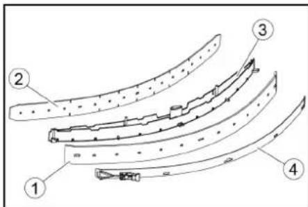
①Sito za grobo umazanijo
②Sito za kosme
2. Sito za grobo umazanijo odstranite v smeri navzgor.
3. Sperite sito za grobo umazanijo pod te-
kočo vodo.
4. Vstavite sito za grobo umazanijo v rezervoar za umazano vodo.
Čiščenje plovca in sita za puh
①Plovec
②Stikalo za plovec
③Sito za kosme
2. Plovec sperite s čisto vodo.
3. Stikalo za plovec sperite s čisto vodo.
4. Izvlecite in očistite sito za puh.
Zamenjava kolutne krtače
Napotek
①Filter za svežo vodo ②Zapiralo rezervoarja za svežo vodo
- Izvlecite filter za svežo vodo in ga speri- te s čisto vodo.
- Vstavite filter za svežo vodo.
- Namestite zapiralo rezervoarja za svežo vodo.
2006/42/ES (+2009/127/ES)
2014/30/EU
2014/53/EU (TCU)

H. Jenner
Chairman of the Board of Management

S. Reiser
Director Regulatory Affairs & Certification
Winnenden, 1. 9. 2021
Spis treści
natural_image
Technical line drawing of a vehicle battery pack with attached cables and a close-up inset showing internal components (no text or symbols)①Opaska zaciskowa
②Deska
③Klocek
④Krawędziak
natural_image
Technical line drawing of a front-loading cleaning or inspection machine on a platform (no text or symbols visible)① Wąż ssący
natural_image
Technical line drawing of a mechanical assembly with pulleys and gears (no text or symbols)natural_image
Diagram of a hand holding a flexible hose with directional arrows indicating movement or force (no text or symbols)Składowanie
⚠OSTROŻNIE
①Pływak
2006/42/WE (+2009/127/WE)
2014/30/UE
2014/53/EU (TCU)
71364 Winnenden (Germany)
Tel.: +49 7195 14-0
natural_image
Technical line drawing of a vehicle battery pack with attached cables and a close-up inset showing internal components (no text or symbols)①Bandă de întindere
②Scândură
③Bloc
④Lemn fasonat
natural_image
Technical line drawing of a front-loading cleaning or cleaning machine on a platform (no text or symbols visible)①Furtun de aspirare
② Suspendarea barei de aspiratie
③ Bară de aspiratie
④Manetă de blocare
① Stecher de baterii, partea aparatului
②Stecher de baterii, partea bateriilor
①Maneta de deblocare
natural_image
Technical line drawing of a mechanical assembly with pulleys and gears (no text or symbols)natural_image
Diagram of a hand holding a flexible hose with a device, showing directional arrows (no text or symbols)Depozitarea
⚠PRECAUTIE
Directive UE relevante
2006/42/UE (+2009/127/UE)
2014/30/UE
2014/53/UE (TCU)
Standarde armonizate aplicate
EN 60335-1
EN 60335-2-29
EN 60335-2-72
EN 62233: 2008
EN 55012: 2007 + A1: 2009
EN 61000-3-2: 2014
EN 61000-3-3: 2013
EN 61000-6-2: 2005
EN 61000-6-3: 2007 + A1:2011
TCU
EN 301 511 V12.5.1
EN 300 440 V2.1.1
EN 300 328 V2.2.2
EN 300 330 V2.1.1

H. Jenner
Chairman of the Board of Management
S. Reiser
Director Regulatory Affairs & Certification
71364 Winnenden (Germania)
Tel.: +49 7195 14-0
Fax: +49 7195 14-2212
Winnenden, 2021/09/01
Obsah
Všeobecné upozornenia.... 286
Funkcia.... 286
Na skladovanie sa dá sacia lišta zavesit do priehlbiny na nádrži na znečistenú vodu.
natural_image
Technical line drawing of a cleaning or inspection machine with no visible text or symbols①Nasávacia hadica
②Upevnenie sacej lišty
③Sacia lišta
④Upínacia páka
-
Saciu listu vložte do upevnenia sacej lišty.
-
Otočte obe upínacie páky smerom nadol.
Batérie
① Zástrčka batérie, strana prístroja
② Zástrčka batérie, strana batérie
- Zástrčku na batériu na strane prístroja spojte s nabíjačkou.
- Zasuňte sietovú zástrčku nabíjačky do zásuvky.
- Nabíjanie vykonajte podl'a údajov v návode na obsluhu nabíjačky.
- Zástrčku batérie na strane prístroja spojte so zástrčkou batérie na strane batérie.
- Nádrž na znečistenú vodu otočte smerom dopredu a zatvorte.
Interná nabíjačka
- Odblokujte nádrž na znečistenú vodu a otočte ju smerom dozadu.
- Zasuňte sietovú zástrčku internej nabí- jačky do zásuvky.
Stav nabitia batérie sa zobrazuje na displeji na ovládacom paneli.
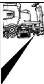
natural_image
Line drawing of a truck with a roof and side-mounted vehicle (no text or symbols)①Páka na odblokovanie
- Na oboch koncoch páky zasuňte mincu medzi kryt a páku.
- Uvol'nite páku na odblokovanie.
- Presuňte zariadenie.
- Ihned' po procese presúvania opät' odstráňte obe mince.
Nastavenie sedadla
Nastavenie výšky
natural_image
Technical line drawing of a mechanical assembly with pulleys and gears (no text or symbols)①Matica
natural_image
Diagram of a hand holding a flexible hose connected to a rectangular device with ventilation slots (no text or symbols)Skladovanie
⚠UPOZORNENIE
①Stierka
① Filter na hrubé nečistoty
②Filter na žmolky
- Filter na hrubé nečistoty vytiahnite nahor.
- Filter na hrubé nečistoty očistite pod tečúcou vodou.
- Filter na hrubé nečistoty vložte do nádrže na znečistenú vodu.
Čistenie plaváka a filtra na žmolky
①Rukovät výmeny kief
② Veko ložiska so stierkou
③Valcová kefa
①Filter čistej vody
2006/42/ES (+2009/127/ES)
2014/30/EÚ
2014/53/EÚ (TCU)
71364 Winnenden (Germany)
Tel.: +49 7195 14-0
Fax: +49 7195 14-2212
Winnenden, 01.09.2021
Sadržaj
Opće napomene 300
Funkcija.... 301
① * Bočni piling prekidač
②Sirena
③Prekidač smjera
④Prekidač programa
⑤Inteligentni ključ
⑥Zaslon
⑦Gumb za informacije
⑧Sigurnosna sklopka
Sklopka za odabir programa

①Isklj. (OFF)
natural_image
Technical line drawing of a vehicle battery pack with two views showing internal components (no text or symbols)Posuda za prskanje može se objesiti u udubljenje na spremniku prljave vode za odlaganje.
Simboli na uređaju

①Remen
②odbor
③Prijava
④Drveni blok
-
Odvijte blokove, kvadrate i ploče. Komponente za odvrtanje su na slici označene sivom bojom.
-
Ispred palete postavite rampu s odvijenim pločama i četverokutom drveta i pričvrstite ih vijcima za ivericu.
-
Odvijte blokove, kvadrate i ploče. Komponente za odvrtanje su na slici označene sivom bojom.
- Ispred palete postavite rampu s odvijenim pločama i četverokutom drveta i pričvrstite ih vijcima za ivericu.

natural_image
Technical line drawing of a cleaning or inspection machine with no visible text or symbols①Usisno crijevo
① Utikač akumulatora, strana uređaja
② Utikač akumulatora, strana akumulatora
3. Utikač akumulatora na strani akumulatora spojite s punjačem.
4. Utaknite strujni utikač punjača u utičnicu.
5. Postupak punjenja provedite prema na-
vodima u uputama za uporabu punjača.
6. Utikač akumulatora na strani uređaja spojite s utikačem akumulatora na strani akumulatora.
7. Pomaknite spremnik otpadnih voda prema naprijed i zatvorite ga.
Unutarnji punjač
- Otključajte spremnik otpadnih voda i prebacite ga natrag.
- Utaknite strujni utikač punjača u utičnicu. Stanje napunjenosti akumulatora prikazuje se na zaslonu stroja za metenje.
- Za završetak postupka punjenja izvucite mrežni utikač punjača iz utičnice.
- Spremnik prljave vode zakrenite prema dolje.
Akumulatori koji ne zahtijevaju održavanje (elektrolitski akumulatori)
△OPASNOST
① Otključavajuća poluga
- Umetnite novčić između kućišta i poluge na oba kraja poluge.
- Otpustite ručicu za otpuštanje.
- Gurnite uređaj.
- Izvadite obje kovanice odmah nakon gu- ranja.
Podesite sjedalo
Podešavanje visine
natural_image
Technical line drawing of a mechanical assembly with pulleys and gears (no text or symbols)①Vijak
②Matica
③Razina vode
5. Otpustite maticu.
6. Podesite vijak tako da indikator razine bude između dvije linije.
7. Zategnite maticu.
8. Da biste provjerili novu postavku, ponovo pomaknite uređaj na kratku udaljenost. Po potrebi ponovite postupak podešavanja.
9. Prekidač s ključem okrenite u položaj 0/OFF.
Podešavanje visine
Podešavanje visine utječe na zakrivljenost gumica za usisavanje pri kontaktu s po- dom.
Napomena
①Matica
② Podloška
natural_image
Diagram showing a hand connecting a device with a coiled cable, indicating fluid or mechanical interaction (no text or symbols present)①Poklopac spremnika prljave vode
②Nastavci
③Stupanj
- Ako je potrebno, napunite akumulator.
Sivi inteligentni ključ
Sivi inteligentni ključ daje nadzornom osoblju proširena odobrenja i mogućnosti postavljanja.
-
Umetnite inteligentni ključ.
-
Pomoću gumba s informacijama odaberite željenu funkciju.
Transportna vožnja
-
Postavite sklopku za odabir programa na "TRANSPORT MODE".
-
Pritisnite gumb za informacije.
U izborniku TRANSPORT MODE mogu se izvršavati sljedeće funkcije:
• Postavljanje maksimalne brzine
natural_image
Top-down technical diagram of a vehicle showing structural components and engine assembly (no text or labels)Skladištenje
△OPREZ
Nepridržavanje težine
①Zvjezdasta ručka
②Zatezna traka
①Gumica za struganje
②Potporna gumica
①Plovak
②Plutati prekidač
2006/42/EZ (+2009/127/EZ)
2014/30/EU
2014/53/EU (TCU)
Primijenjene nacionalne norme
EN 60335-1
EN 60335-2-29
EN 60335-2-72
EN 62233: 2008
EN 55012: 2007 + A1: 2009
EN 61000-3-2: 2014
EN 61000-3-3: 2013
EN 61000-6-2: 2005
EN 61000-6-3: 2007 + A1:2011
TCU
EN 301 511 V12.5.1
EN 300 440 V2.1.1
EN 300 328 V2.2.2
EN 300 330 V2.1.1
Primijenjene nacionalne norme

Chairman of the Board of Management

S. Reiser
Director Regulatory Affairs & Certification
Opunomoćenik za dokumentaciju: S. Reiser
Alfred Kärcher SE & Co. KG
Alfred-Kärcher-Str. 28 - 40
71364 Winnenden (Njemačka)
Tel.: +49 7195 14-0
Telefaks: +49 7195 14-2212
Winnenden, 01.09.2021.
Sadržaj
Opšte napomene.... 315
Funkcija 315
Namenska upotreba 315
① Sistem punjenja
② Zatvarač rezervoara za svežu vodu sa filterom za svežu vodu
③Mrežica za grubu prljavštinu
④Poklopac rezervoara za prljavu vodu
⑤Komandno polje
⑥Točak za podešavanje gumica za prikupljanje prljavštine (samo D glava za čišćenje)
⑦ Pedala za zamenu četki (samo D glava za čišćenje)
⑧Upravljač
⑨Gumice za prikupljanje prljavštine
⑩ Ručka za zamenu četki (samo R glava za čišćenje)
⑪Bočno svetlo
⑫Kontejner za grubu prljavštinu (samo R glava za čišćenje)
⑬ Kanister sredstva za čišćenje
⑭Natpisna pločica
⑮Deterdžent za usisno crevo
⑯Baterija
⑰* Interni punjač
18 Adapter za baterije (kod eksternog punjača)
Mrežni kabl punjača (kod internog punjača)
⑲Prostor za odlaganje kompleta za čišćenje „Homebase Box“
20 * Upozoravajuće svetlo
21Sedište
②2 Taster za deblokadu rezervoara za prljavu vodu
23Polugu za podešavanje sedišta
⑳Otvor za punjenje rezervoara za svežu vodu
25Držač creva
26 Svetlo za dnevnu vožnju
27 Pedala gasa
28 * Bočna ploča za čišćenje
29 * Priključak za vodu za sistem za ispiranje rezervoara za prljavu vodu
30 Nastavak poklopca rezervoara za prljavu vodu
31Plovak
32Mrežica za skupljanje vlakana
③3 Prihvatni držač za usisnu konzolu
③4 Ispusno crevo za prljavu vodu sa uređajem za doziranje
35Rezervoar za prljavu vodu
③6 * Držač brisača za pod
37 Usisno crevo
38 Stezna poluga usisne konzole
⑲ 39 Zatvarač rezervoara za prljavu vodu
④0Usisna konzola
④1 Glava za čišćenje
④2 Pokazivač napunjenosti sveže vode
④3Rezervoar za svežu vodu
* opciono
Identifikacija boje
- Komandni elementi za postupak čišćenja su žuti.
- Komandni elementi za održavanje i servis su svetlo sivi.
Komandno polje
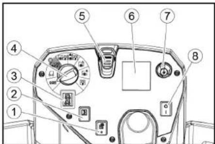
① *Prekidač bočne ploče za čišćenje
②Sirena
③Prekidač za smer kretanja
④Programski prekidač
⑤ Intelligent Key
⑥Ekran
⑦Dugme za informacije
⑧Sigurnosni prekidač
Programski prekidač
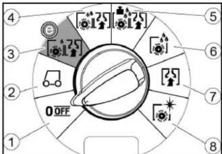
①OFF
natural_image
Technical line drawing of a vehicle battery pack with two views showing internal components (no text or symbols)Za skladištenje se usisna konzola može okačiti na udubljenje na rezervoaru za prljavu vodu.
Simboli na uređaju

①Zatezna traka
②Tabla
③ Drveni blok
④Drvena kocka
-
Odvijte drveni blok, drvene kocke i daske. Komponente za odvrtanje su na slici označene sivom bojom.
-
Napravite rampu ispred palete od odvrnutih dasaka i drvenih kocki i pričvrstite je pričvrsnim zavrtnjima.
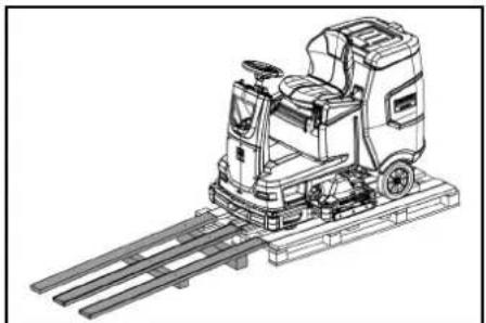
natural_image
Technical line drawing of a front-loading cleaning or inspection machine with railings (no text or symbols)- Montirajte baterije, ukoliko je uređaj isporučen bez baterija (pogledajte poglavlje „Pre puštanja u pogon/baterije“).
- Uređaj vozite unapred sa palete (pogledajte poglavlje „Rad/vožnja“).
Montaža četki
- Montaža četki je opisana u poglavlju „Radovi na održavanju“.
Montaža usisne konzole
- Obe stezne poluge zakrenite prema gore.
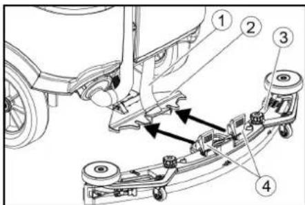
①Usisno crevo
②Kačenje usisne konzole
③Usisna konzola
④Stezna poluga
-
Usisnu konzolu postaviti u kačenje usisne konzole.
-
Obe stezne poluge zakrenite prema dole.
Akumulatori
Preporučeni komplet baterija
| Opis Kataloški br. | Zapremi na (m3)* | Vazdušna struja (m3/h)** | |
| 170 Ah - bez održavanja, AGM | 4.039-352.7 | 2,4 1,0 | |
| 180 Ah - bez održavanja, Gel | 4.039-354.7 | 3,8 1,6 | |
| 285 Ah - bez održavanja, AGM | 4.039-353.7 | 12,6 5,1 | |
* Minimalna zapremina prostora za punjenje akumulatora
** Minimalni protok vazduha između prostora punjača za akumulator i okoline
① Utikač akumulatora, na strani uređaja
② Utikač akumulatora, na strani akumulatora
3. Utikač akumulatora na strani akumulatora povezati sa punjačem.
4. Strujni utikač punjača utaknite u utičnicu.
5. Postupak punjenja vršiti prema podacima u uputstvu za rad punjača.
6. Utikač akumulatora na strani uređaja povezati sa utikačem akumulatora na strani akumulatora.
7. Rezervoar za prljavu vodu nakrenite ka napred i zatvorite ga.
Interni punjač
①Poluga za deblokadu
- Na oba kraja poluge stavite kovanicu između kućišta i poluge.
- Otpustite polugu za deblokadu.
- Gurnite uređaj.
- Izvadite obe kovanice odmah nakon postupka guranja.
Podešavanje sedišta
Podešavanje visine
- Stanite pored uređaja.
- Podignite sedište pozadi.
- Postavite prednji držač sedišta na željenu visinu uređaja.
- Spustite sedište pozadi.
natural_image
Technical line drawing of a mechanical assembly with numbered components (no text or symbols)①Zavrtanj
②Navrtka
③Vaser-vaga
©
- Prikaz verzije softvera
- Podešavanje R ili D glave za čišćenje
- Uključivanje / isključivanje doziranja vode zavisnog od brzine
- Podešavanje trajanja zaustavnog hoda
- Podešavanje jezika
• Upravljanje ključem - Uključivanje / isključivanje dodataka
• Aktiviranje fabričkih podešavanja
Maksimalna brzina
U meniju „max speed“ može da se ograniči radna brzina.
- Okrećite dugme za informacije dok se na ekranu ne prikaže „max speed“.
- Pritisnite dugme za informacije.
- Okrećite dugme za informacije dok se ne prikaže željena maksimalna brzina.
- Pritisnite dugme za informacije.
Napomena
Radna brzina ne može da premaši podešenu maksimalnu brzinu.
Skladištenje
△OPREZ
①Zvezdasta ručka
②Zatezna traka
③Unutrašnji deo usisne konzole
④Zatezna brava
- Izvucite unutrašnji deo usisne konzole.
- Otvorite zateznu bravu.
- Skinite zateznu traku.
- Otpustite gumice za usisavanje sa unutrašnjeg dela.
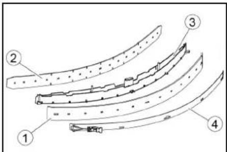
①Gumice za prikupljanje prljavštine
②Dodatna gumica
③Unutrašnji deo usisne konzole
④Zatezna traka
- Korišćene ili nove gumice za usisavanje gurnite na klinove unutar usisne konzole.
- Stavite zateznu traku.
- Gurnite unutrašnji deo usisne konzole u gornji deo.
- Zaviti i pričvrstiti zavrtnjima zvezdaste ručice.
Čišćenje mrežice za grubu prljavštinu
- Otvoriti poklopac rezervoara za prljavu vodu.
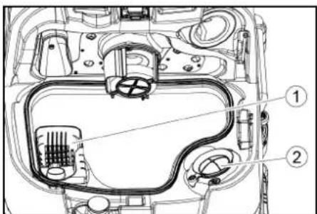
①Mrežica za grubu prljavštinu
②Mrežica za skupljanje vlakana
2. Mrežicu za grubu prljavštinu skinuti prema gore.
3. Mrežicu za grubu prljavštinu isprati pod mlazom vode.
4. Mrežicu za grubu prljavštinu umetnuti u rezervoar za prljavu vodu.
Čišćenje plovka i mrežice za skupljanje vlakana
- Otvoriti poklopac rezervoara za prljavu vodu.
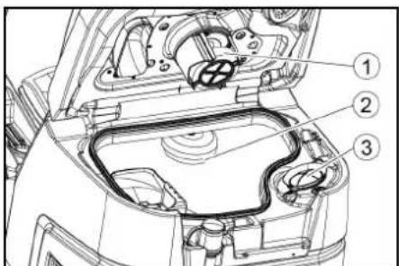
①Plovak
②Prekidač sa plovkom
③Mrežica za skupljanje vlakana
2. Isperite plovak čistom vodom.
3. Isperite prekidač sa plovkom čistom vodom.
4. Skinite i očistite mrežicu za skupljanje vlakana.
① Ručka za zamenu četki
②Poklopac skladišta sa gumicom za prikupljanje prljavštine
③Valjkasta četka
-
Skinite poklopac skladišta sa gumicama za prikupljanje prljavštine.
-
Izvucite valjkastu četku.
-
Stavite novu valjkastu četku i centrirajte je na obrtaču.
①Prihvatnik
②Prihvatni trn
① Četke, deo za bočno ribanje
②Poluga za zamenu četki
Četka ispada iz držača.
2. Novu četku držite ispod bočne ploče za čišćenje, pritisnite prema gore i uglavite
Čišćenje filtera za svežu vodu
①Filter za svežu vodu
② Zatvarač rezervoara za svežu vodu
3. Izvaditi filter za svežu vodu i isprati ga čistom vodom.
4. Umetnuti filter za svežu vodu.
5. Postaviti zatvarač rezervoara za svežu vodu.
Napomena: Obratiti pažnju da se priključak creva u zatvaraču rezervoara za svežu vodu nalazi u najnižoj tački nakon pričvršćivanja zavrtnjima.
Čišćenje šipke za raspodelu vode
- Pritisnite bravicu za deblokadu u pravcu strelice i držite čvrsto.

- Šipku za raspodelu vode zakrenite prema napred.
- Izvucite šipku za raspodelu vode uzdužno.
- Očistite šipku za raspodelu vode.
- Šipku za raspodelu vode ponovo stavite u glavu za čišćenje i užlebite bravicu.
Čišćenje baterija
- Nosite zaštitne naočare, zaštitnu odeću i zaštitne rukavice.
- Držite čepove baterija zatvorenim.
- Demontirajte baterije.
- Plastične delove baterija i prostor za baterije čistite samo vodom ili krpama za čišćenje natopljenim vodom bez dodataka.
- Osušite površine nakon čišćenja.
- Ponovo stavite baterije.
2006/42/EZ (+2009/127/EZ)
2014/30/EU
2014/53/EU (TCU)

Chairman of the Board of Management

S. Reiser
Director Regulatory Affairs & Certification
Lice ovlašćeno za dokumentaciju: S. Reiser
Alfred Kärcher SE & Co. KG
Alfred-Kärcher-Str. 28 - 40
71364 Winnenden (Germany)
Tel.: +49 7195 14-0
Winnenden, 2021/09/01
Съдържание
Общи указания.... 330
Функция 330
Употреба по предназначение...... 330
natural_image
Technical line drawing of a vehicle battery pack with attached cables and a close-up inset showing internal components (no text or symbols)①Стягаша лента
②Дъска
③Трупче
④Дървена греда
natural_image
Technical line drawing of a cleaning or inspection machine with no visible text or symbols① Щепсел на акумулатора, страна на уреда
natural_image
Technical line drawing of a mechanical assembly with pulleys and gears (no text or symbols)①ВИНТ
②Гайка
natural_image
Diagram showing a hand holding a flexible hose connected to a device with directional arrows indicating movement (no text or symbols)Съхранение
⚠ПРЕДПАЗЛИВОСТ
①Поплавък

H. Jenner
Chairman of the Board of Management

S. Reiser
Director Regulatory Affairs & Certification
71364 Winnenden (Germany)
Тел.: +49 7195 14-0
Факс: +49 7195 14-2212
Виненден, 2021/09/01
Sisukord
Üldised juhised 347
Funktsioon 347
① Täitesüsteem
①* Külgharjadeki lüliti
②Sireen
③Sõidusuuna lüliti
④Programmilüliti
⑤Nutivõti
⑥Displei
⑦Infonupp
⑧Turvalüliti
Programmilüliti

①OFF
Imitala saab hoiustamiseks riputada süvendisse mustaveepaagil.
①Pingutuslint
②Laud
③Klots
④Puitpruss
natural_image
Technical line drawing of a mechanical cleaning or inspection machine with no visible text or symbolsImitala monteerimine
①Imivoolik
②Imitala ripphoidik
③Imitala
④Lukustushoob
2. Pange imitala ripphoidikusse.
3. Pöörake mölemad lukustushoovad alla.
Akud
Soovitatavad akud
| Kirjeldus | Tellimisnr | Maht (m3)* | Öhu-vool (m3/h)** |
| 170 Ah – hooldus-vaba, AGM | 4 039-352.7 | 2,4 1,0 | |
| 180 Ah – hooldus-vaba, Gel | 4 039-354.7 | 3,8 1,6 | |
| 285 Ah – hooldus-vaba, AGM | 4 039-353.7 | 12,6 5,1 |
①Vabastushoob
natural_image
Technical line drawing of a mechanical assembly with labeled components (no text or symbols present)①Polt
②Mutter
③Vesilood
①Mutter
②Alusseib
natural_image
Diagram showing a hand holding a flexible hose connected to a rectangular device with internal components (no text or symbols)Ladustamine
△ETTEVAATUS
Kaalu eiramine
①Tähtkinnitus
②Pingutuslint
③Imitala sisemine osa
④Pingutuslukk
①Pesurihuul
②Tugihuul
③Imitala sisemine osa
④Pingutuslint
①Puhtaveefilter
②Puhtaveepaagi sulgur
2006/42/EÜ (+2009/127/EÜ)
2014/30/EL
2014/53/EL (TCU)
71364 Winnenden (Germany)
Tel: +49 7195 14-0
Winnenden, 2021/09/01
Saturs
①Spriegotājsiksna
②Dēlis
③Klucis
④Brusa
natural_image
Technical line drawing of a front-loading cleaning or inspection machine on a platform (no text or symbols visible)① Sūkšanas šljutene
① Akumulatora spraudnis, ierīces pusē
②Akumulatora spraudnis, akumulatora pusē
①Atblokēšanas svira
natural_image
Technical line drawing of a mechanical assembly with numbered components (no text or symbols)natural_image
Diagram showing a hand connecting a flexible hose to a device with arrows indicating force or movement (no text or symbols present)Uzglabāšana
⚠UZMANĪBU
Svara neievērošana
①Pludinš
② Pludinslēdzis
③Pūku siets
① Sānu suku sistēmas suka
②Sukas nomainas svira
① * Šoninio šveitimo įtaiso jungiklis
②Garsinis signalas
①Suveržimo juosta
②Lenta
③Trinkelé
④Medinis tašas
natural_image
Technical line drawing of a front-loading cleaning or inspection machine on a platform (no text or symbols visible)① Siurbimo žarna
natural_image
Line drawing of a truck with a roof and side-mounted vehicle, no text or symbols present①Atblokavimo svirtis
natural_image
Technical line drawing of a mechanical assembly with pulleys and gears (no text or symbols)①Veržlé
②Poveržlé
natural_image
Diagram showing a hand connecting a flexible hose to a device with directional arrows indicating movement (no text or symbols)①Nešvaraus vandens bako dangtis
②Atrama
③Režimas
5. Prireikus ikraukite baterija.
Sandėliavimas
ATSARGIAI
①Šepečio keitimo rankena
②Guolio dangtis su valymo grandikliu
③ Šepetinis velenas
①Švaraus vandens filtras
②Švaraus vandens bako dangtelis

Chairman of the Board of Management

S. Reiser
Director Regulatory Affairs & Certification
natural_image
Technical line drawing of a front-loading cleaning or inspection machine on a platform (no text or symbols visible)
natural_image
Line drawing of a truck with a gear and wheel, no text or symbols presentnatural_image
Technical line drawing of a mechanical assembly with pulleys and gears (no text or symbols)①Гайка
natural_image
Diagram showing a hand connecting a plastic component with a coiled hose, indicating fluid or electrical connection (no text or symbols present)Зберігання
⚠ОБЕРЕЖНО
Недотримання ваги

H. Jenner
Chairman of the Board of Management

S. Reiser
Director Regulatory Affairs & Certification
71364 Winnenden (Germany)
Тел.: +49 7195 14-0
Факс: +49 7195 14-2212
①* 충진 시스템
①* 사이드 스크럼 네크 스위치
②경음기
③주행방향 스위치
④프로그램 스위치
⑤인 델리전드 키
⑥더스플레이
⑦정보 버튼
⑧안전 스위치
프로그램 스위치

①OFF
장비가 끼졌습니다.
②TRANSPORT MODE
사용 장소로 주행하십시오.
③ECO MODE
①고정 벨트
②甲、三
③분록
④각목
natural_image
Technical line drawing of a mechanical or industrial robotic platform with no visible text or symbols①흡입호스
②진공바 현가장치
③진공바
④조임 레버
①배티리 폴리그,장비 측
②베터리 폴러그,베터리 측
①해제 레비
natural_image
Technical line drawing of a mechanical assembly with pulleys, gears, and levers (no text or symbols)①나사
②L·E
③액면계
①너드
②와서
③홀더가 포함된 스페이서 몰러
natural_image
Diagram of a hand holding a flexible hose connected to a rectangular device with internal components, showing directional arrows (no text or symbols)①폐수 탱크 뚜껑
②지지부
③단계
5.필요시배터리를충전합니다.
회색 인텔리전트 키
| 세팅 ON [ml/m2] OFF [l/min] | ||
| 0% 0 0 | ||
| 10% 7.5 0.6 | ||
| 20% 15 1.1 | ||
| 30% 22.5 1.7 | ||
| 40% 30 2.3 | ||
| 50% 37.5 2.8 | ||
| 60% 45 3.4 | ||
| 70% 52.5 3.9 | ||
| 80% 60 4.5 | ||
| 90% 67.5 5.1 | ||
| 100% 75 5.7 | ||
natural_image
Top-down technical sketch of a car interior with structural details and a close-up inset showing dashboard and engine components (no text or labels)보관
△ 주의
무게 미준수
부상 및 손상 위험
①스타그림
②고정 멜트
③진공바 내측 부분
④결쇠형 잠금장치
①군 요염물 체
②보품 핀터
①브리시 교환 손잡이
②와이핑 플랩이 포함된 베어링 커버
③브리시 톨리

H. Jenner
Chairman of the Board of Management
S. Reiser
Director Regulatory Affairs & Certification
문서 작성 책임자:
S. Reiser
Alfred Kärcher SE & Co. KG
Alfred-Kärcher-Str. 28 - 40
71364 Winnenden (Germany)
전화: +49 7195 14-0
팩스: +49 7195 14-2212
Winnenden, /09/01
目录
一般性注意事项 421
功能 421
按规定使用 421
环境保护 421
附件和备件 421
供货范围 421
安全提示 421
设备说明 423
安装 424
投入运行 425
运行 426
结束运行 427
灰色智能钥匙 128
运输 428
存放 428
保养和维护 429
故障排除 130
质量保证 431
配件 432
技术数据 432
欧盟一致性声明 434
一般性注意事项
①* 灌装系统
②清水箱封盖,水箱配备清水过滤器
③粗大污染物滤网
④污水箱盖罩
⑤控制面板
⑥削刮胶条调节轮(仅 D 消洁头)
⑦换刷踏板(仅 D 清洁头)
⑧方向盘
⑨削刮胶条
⑩换刷手柄(仅 R 清洁头)
⑪侧灯
⑫粗大污染物容器(仅 R 清洁头)
⑬清洁剂罐
⑭铭牌
⑮清洁剂抽吸软管
⑯蓄电池
⑰* 内置充电器
⑱电池插头(外置充电器)
充电器电源线(内置充电器)
⑲清洁套件“Homebase Box”的存放区域
20* 警告灯
②1座椅
②污水箱解锁件
②3 座椅调节杆
24清水箱加注口
25软管支架
26口间行驶灯
⑳油门踏板
28* 侧刷板
29* 污水箱冲洗系统的接水口
③0污水箱盖支架
③1浮子
③2细滤网
③吸水扒存放位置
③4带计量装置的污水排放软管
③5污水箱
36* 拖把架
③7抽吸软管
③8吸水扒夹紧杆
⑲污水箱封盖
④吸水扒
④1清洁头
④2清水液位表
④3清水箱
* 选配
颜色标记
- 清洁过程的操作元件为黄色。
- 保养和检修的操作元件为浅灰色。
控制面板

①* 侧刷板开关
②喇叭
③行进方向开关
④程序开关
⑤智能钥匙
⑥显示屏
⑦信息按钮
⑧安全开关
程序开关
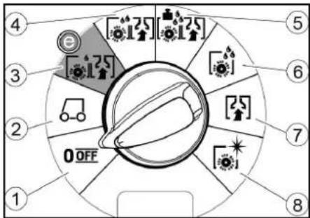
①OFF
设备已关闭。
②TRANSPORT MODE
前往作业区域。
③ ECO MODE
natural_image
Technical line drawing of a vehicle hood and seat assembly (no text or symbols)吸水扒可挂到污水箱上的凹槽中进行存放。
设备上的标志


* 选配
清水箱排放口
污水箱排放口
清水箱液位 (50%)
绑扎点
*拖把架
灌装系统接水口
污水箱冲洗系统接水口
更换毛刷
安装
卸载
-
取下包装膜。
-
拆下紧固带。
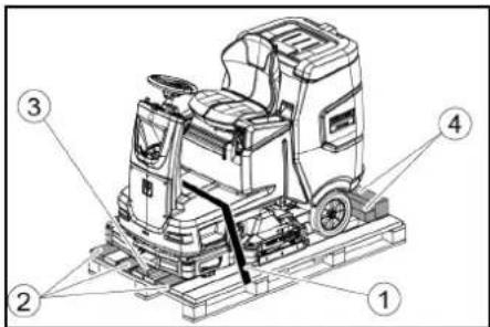
①紧固带
②板
③底座
④方木
natural_image
Technical line drawing of a cleaning or inspection machine on a platform (no text or symbols visible)①电池插头,设备侧
②电池插头,电池侧
①解锁杆
natural_image
Technical line drawing of a mechanical assembly with pulleys and gears (no text or symbols)①螺栓
②螺母
③水平仪
①螺母
②垫片
③间隔滚轮与支架
natural_image
Diagram of a hand holding a flexible hose with directional arrows indicating movement or force (no text or symbols)①污水箱盖罩
②支架
③等级
- 必要时给电池充电。
灰色智能钥匙
| 设置 ON [ml/n | 2] OFF[1/min] | |
| 0% 0 0 | ||
| 10% 7.5 0.6 | ||
| 20% 15 1.1 | ||
| 30% 22.5 1.7 | ||
| 40% 30 2.3 | ||
| 50% 37.5 2.8 | ||
| 60% 45 3.4 | ||
| 70% 52.5 3.9 | ||
| 80% 60 4.5 | ||
| 90% 67.5 5.1 | ||
| 100% 75 5.7 | ||
速度相关或恒定水计量的设定:
存放
△ 小心
忽视重量
受伤与损坏危险
存放时注意设备的重量。
注意
霜冻
冻住的水导致设备损坏
彻底排空设备中的水。
将设备保管在无霜冻的地方。
- 本设备只允许存放在室内。
- 长时间存放之前,要给电池完全充电。
①粗大污染物滤网
②细滤网
①浮子
②浮子开关
③细滤网
①换刷手柄
②带削刮胶条的轴承盖
③刷辊
①侧刷板毛刷
②换刷杆
毛刷从支架上掉出。
S. Reiser
Director Regulatory Affairs & Certification
文档全权代表:
S. Reiser
Alfred Kärcher SE & Co. KG
Alfred-Kärcher-Str. 28 - 40
71364 Winnenden (德国)
电话:+49 7195 14-0
传真:+49 7195 14-2212
Winnenden, 2021/09/01
وال environmentally unfavorable.
① فلتر المياه炎症
① ماخ الخشنة
②Sigma la zogb
-
لى أعلى
-
Mit المياء
الgardية.
- أن المياه
المتسخة.
① عوامة
② تاح العوامة
③Sigma la
النظيفة 2.
3.النظيفة
و teenظيفها 4..
① مقبض تغير الفرشاة
natural_image
Diagram of a medical device with a coiled tube and directional arrows indicating force or movement (no text or symbols)بالوعة الصرف الصحي.
- ضه فوق
① صامولة
② فلكة
natural_image
Technical line drawing of a mechanical assembly with pulleys and gears (no text or symbols)① برغي
② صامولة
③ ميزان ماني
5.حل الصامولة.
جزام ①
لوح ②
③ قرمة
④ خشبة مربعة
- Bhitt Alloac Mfokoka and Achab Merbe
natural_image
Technical line drawing of a mechanical cleaning or inspection machine with no visible text or symbolsnatural_image
Technical line drawing of a vehicle hood and seat assembly, showing front and side views with no text or symbols"0"Amans on the Waste
natural_image
Black silhouette of a hand giving a thumbs-up gesture (no text or symbols)THANK YOU!
MERCI! DANKE! iGRACIAS!

Register your product and benefit from many advantages.
www.kaercher.com/welcome


Rate your product and tell us your opinion.
natural_image
Icon showing a gear and wrench inside a square frame (no text or symbols)www.kaercher.com/dealersearch
Alfred Kärcher SE & Co. KG
Alfred-Kärcher-Str. 28-40
71364 Winnenden (Germany)
Tel.: +49 7195 14-0
Fax: +49 7195 14-2212


- Inhalt
- Lagerung
- △VORSICHT
- Contents
- General notes
- Function
- Note
- Intended use
- Environmental protection
- Accessories and spare parts
- Scope of delivery
- Safety instructions
- ⚠ WARNING
- The device can tip over
- △WARNING
- Risk of accident due to incorrect operation
- Safety devices
- △CAUTION
- Missing or modified safety devices
- Safety switch
- Seat switch
- Symbols on the device
- ATTENTION
- Risk of damage
- ⚠CAUTION
- Danger of burns
- △DANGER
- Danger of accident
- Warning symbols
- Description of the unit
- Overview of the device
- Colour coding
- Installation
- Unloading
- Installing he brushes
- Installing the suction bar
- Batteries
- Installing and connecting batteries
- Removing the battery
- Initial startup
- Charging the battery
- External charger
- Internal charger
- Low-maintenance batteries (wet batteries)
- Refilling discharged batteries with water
- Using water with additives
- Operation
- Falling objects
- Risks during operation
- Pushing the device
- Adjusting the seat
- Adjusting the height
- Adjusting the position
- Switching the device on
- Switching on the light
- Daytime running light
- Sidelight
- Checking the parking brake
- Defective parking brake
- Driving
- Lack of braking
- Careless driving
- Filling with fresh water
- Filling with fresh water via the filling system
- Filling with detergent
- Notes on detergents
- Unsuitable detergents
- Filling detergent via the dosing device Only with DOSE variant:
- Filling the detergent into the fresh water tank
- Adjusting parameters
- Yellow Intelligent Key
- Adjusting the suction bar
- Adjusting the inclination
- Adjusting the squeegee blades
- Cleaning
- Side scrubbing deck (option)
- Finishing operation
- Finishing cleaning
- Draining the waste water
- Waste water tank rinsing system (option)
- Empty the coarse dirt container
- Draining fresh water
- Shutting down the unit
- Grey Intelligent Key
- Transport journey
- Maximum speed
- Resetting the maintenance counter
- Adjusting the cleaning head
- Speed-dependent water dosing
- Set speed-dependent or constant water dosing:
- After-running time
- Setting the language
- Key management
- Switch attachment kits on / off
- Factory setting
- Adjusting parameters for cleaning programs
- Transport
- Driving on slopes
- Failure to observe the weight
- Storage
- Frost
- Care and maintenance
- Inadvertently starting up device
- Maintenance intervals
- Each time after use
- Improper cleaning
- Weekly
- Monthly
- Annually
- Safety inspection/maintenance contract
- Maintenance work
- Turn over or replace the worn suction lips
- Cleaning the coarse dirt filter
- Cleaning the float and fluff filter
- Replacing the disc brush
- Replacing the roller brushes
- Replacing the side scrubbing deck brush (option)
- Cleaning the fresh water filter
- Cleaning the water distribution strip
- Cleaning batteries
- Troubleshooting guide
- The device can start unintentionally
- Malfunctions with information shown on the display
- Warranty
- Accessories
- Cleaning head with roller brush accessories
- Cleaning head with disc brushes accessories
- Suction bar accessories
- Declaration of Conformity
- EU Declaration of Conformity
- Currently applicable EU Directives
- Applied harmonized standards
- TCU
- National standards used
- Declaration of Conformity (UK)
- Currently applicable UK Regulations
- Contenu
- ⚠ PRÉCAUTION
- Accessori e ricambi
- ⚠️PRUDENZA
- Mancata osservanza del peso
- Inhoud
- Kleurmarkering
- Opslag
- ⚠VOORZICHTIG
- Almacenamiento
- △PRECAUCIÓN
- Indice
- Armazenamento
- △CUIDADO
- Indhold
- Opbevaring
- ⚠FORSIGTIG
- Batterier
- ①Lås opp spaken
- Merknad
- Lagring
- ⚠FORSIKTIG
- Rengjøre grovsmussilen
- Anvendte harmoniserte standarder
- Innehåll
- Förvaring
- ⚠FÖRSIKTIGHET
- Sisältö
- Varastointi
- △VARO
- Αποθήκευση
- ΔΠΡΟΣΟΧΗ
- İçindekiler
- Depolama
- TEDBIR
- Содержание
- Хранение
- ⚠ ОСТОРОЖНО
- Несоблюдение веса
- Raktározás
- ⚠VIGYÁZAT
- Obsah
- Skladování
- ⚠UPOZORNĚNÍ
- Kazalo
- Namestitev krtač
- Nastavljanje višine
- Sistem splakovanja rezervoarja za umazano vodo (opcija)
- Sivi ključ Intelligent Key
- Skladiščenje
- △PREVIDNOST
- Neupoštevanje teže
- Čiščenje plovca in sita za puh
- Zamenjava kolutne krtače
- Napotek
- Spis treści
- Składowanie
- ⚠OSTROŻNIE
- Depozitarea
- ⚠PRECAUTIE
- Directive UE relevante
- Standarde armonizate aplicate
- Batérie
- Interná nabíjačka
- Nastavenie sedadla
- Nastavenie výšky
- ①Matica
- Skladovanie
- ⚠UPOZORNENIE
- Čistenie plaváka a filtra na žmolky
- Sadržaj
- Sklopka za odabir programa
- Simboli na uređaju
- Unutarnji punjač
- Akumulatori koji ne zahtijevaju održavanje (elektrolitski akumulatori)
- △OPASNOST
- Podesite sjedalo
- Podešavanje visine
- Napomena
- Sivi inteligentni ključ
- Transportna vožnja
- Skladištenje
- △OPREZ
- Nepridržavanje težine
- Primijenjene nacionalne norme
- Identifikacija boje
- Komandno polje
- Programski prekidač
- Montaža četki
- Montaža usisne konzole
- Akumulatori
- Interni punjač
- Podešavanje sedišta
- Maksimalna brzina
- Čišćenje mrežice za grubu prljavštinu
- Čišćenje plovka i mrežice za skupljanje vlakana
- Čišćenje filtera za svežu vodu
- Čišćenje šipke za raspodelu vode
- Čišćenje baterija
- Съдържание
- Съхранение
- ⚠ПРЕДПАЗЛИВОСТ
- Sisukord
- Imitala monteerimine
- Akud
- Soovitatavad akud
- ①Vabastushoob
- Ladustamine
- △ETTEVAATUS
- Kaalu eiramine
- Saturs
- Uzglabāšana
- ⚠UZMANĪBU
- Svara neievērošana
- Sandėliavimas
- ATSARGIAI
- Зберігання
- ⚠ОБЕРЕЖНО
- ①해제 레비
- 회색 인텔리전트 키
- 보관
- △ 주의
- 目录
- 一般性注意事项
- 颜色标记
- 控制面板
- 程序开关
- 设备上的标志
- 安装
- 卸载
- ①解锁杆
- 灰色智能钥匙
- 速度相关或恒定水计量的设定:
- 存放
- △ 小心
- 忽视重量
- 注意
- 霜冻
- THANK YOU!
- MERCI! DANKE! iGRACIAS!
Brand : Kärcher
Model : B 110 R Bp Pack
Category : Scrubber