
HWA 60005 Premium - Pump AL-KO - Free user manual and instructions
Find the device manual for free HWA 60005 Premium AL-KO in PDF.
| Product type | Domestic booster pump |
| Brand | AL-KO |
| Model | HWA 60005 Premium |
| Power supply | 230 V ~ 50 Hz |
| Protection | Thermal and dry-run protection |
| Maximum pressure | 4.0 bar |
| Maximum flow rate | 6000 L/h |
| Max. water temperature | 35 °C |
| Application | Clean water and rainwater |
| Pump type | Self-priming |
| Noise level | 73 dB(A) measured / 75 dB(A) guaranteed |
| Suction connection | 1" (thread) |
| Pressure connection | 1" (thread) |
| Display | Digital screen with pressure and flow |
| Control | MODE and SET buttons |
| Delivery contents | Pump, filter key, elbow connectors, seals, manual |
| Maintenance | Filter cleaning, non-return valve, float body |
| Safety | Residual current circuit breaker <30 mA recommended |
| Warranty | CE conformity |
| Options | Language setting, total and partial volume display |
Frequently Asked Questions - HWA 60005 Premium AL-KO
User questions about HWA 60005 Premium AL-KO
0 question about this device. Answer the ones you know or ask your own.
Ask a new question about this device
Download the instructions for your Pump in PDF format for free! Find your manual HWA 60005 Premium - AL-KO and take your electronic device back in hand. On this page are published all the documents necessary for the use of your device. HWA 60005 Premium by AL-KO.
USER MANUAL HWA 60005 Premium AL-KO
AL-KO KOBER GROUP Kottz, Germany
This documentation or excerpts therefrom may not be reproduced or disclosed to third parties without the express permission of the AL-KO KOBER GROUP.
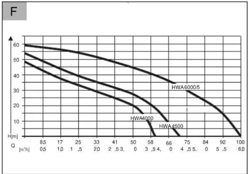
| HWA 4000 comfort (Art.Nr. 113 139) | HWA 4500 comfort (Art.Nr. 113 140) | HWA 6000/5 Premium (Art.Nr. 113 141) |
| 1000 W 1300 W 1400 W | ||
| 230 V AC/50 Hz 230 V AC/50 Hz 230 V AC/50 Hz | ||
| X 4 X 4 X 4 | ||
| 81 dB (A) 81 dB (A) 73 dB (A) | ||
| 8 m 8 m 8 m | ||
| 45 m / 4,5 bar 50 m / 5,0 bar 60 m / 6,0 bar | ||
| 4000 l/h 4500 l/h 6000 l/h | ||
| 35 °C 35 °C 35 °C | ||
| 1" 1" 1" | ||
| 11 kg 11,2 kg 14,1 kg | ||
| 1 1 5 | ||
About this handbook. 14
Product description. 14
Scope of delivery. 15
Safety instructions. 15
Assembly. 16
Startup 16
Maintenance and care. 17
Storage. 18
Displayindications. 18
Troubleshooting 20
Disposal. 21
Warranty 21
EU declaration of conformity. 22
PRODUCT DESCRIPTION
This documentation describes various different unit models. Identify your model using the identification plate.
Product overview
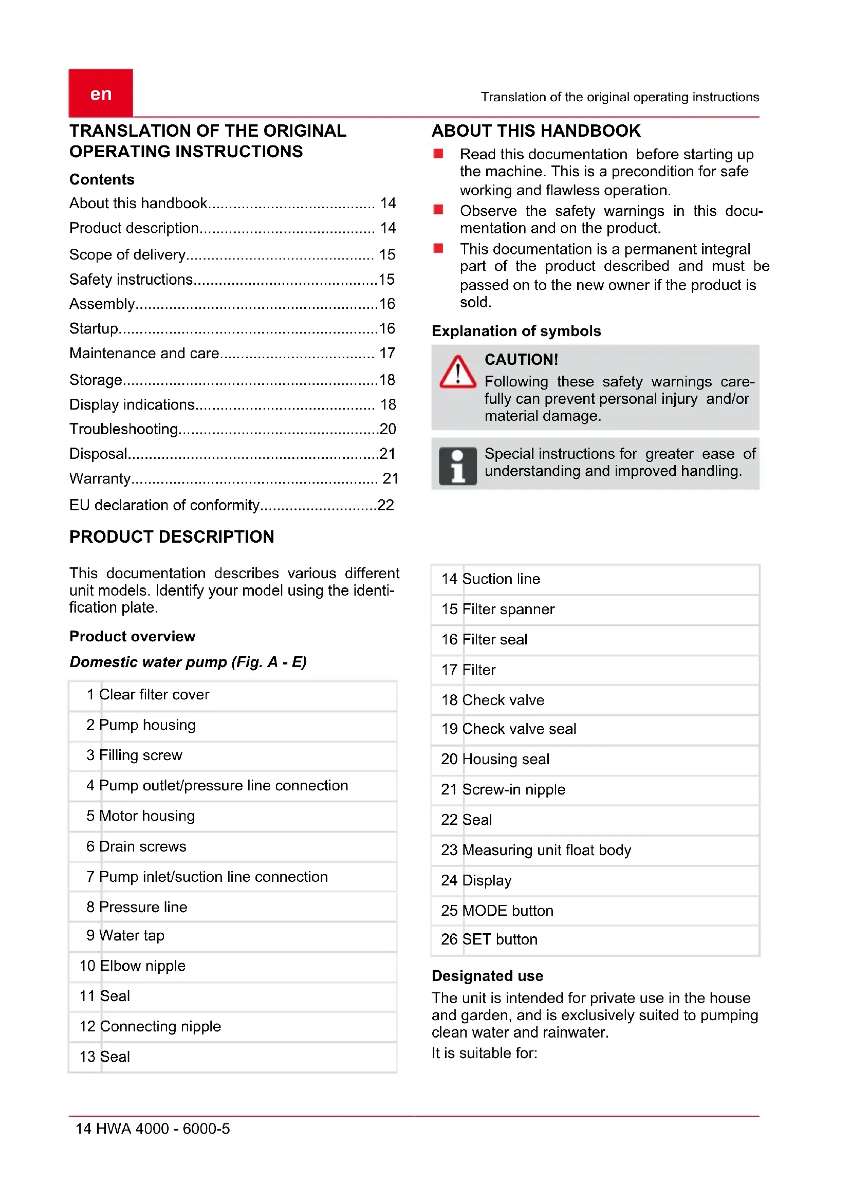
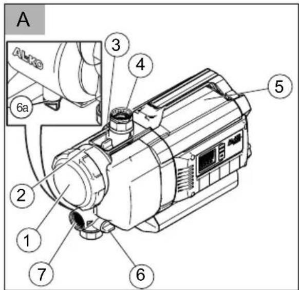
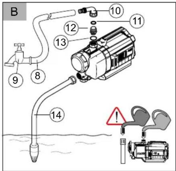
Domestic water pump (Fig. A - E)
1 Clear filter cover
2 Pump housing
3 Filling screw
4 Pump outlet/pressure line connection
5 Motor housing
6 Drain screws
7 Pump inlet/suction line connection
8 Pressure line
9 Water tap
10 Elbow nipple
11 Seal
12 Connecting nipple
13 Seal
ABOUT THIS HANDBOOK
Read this documentation before starting up the machine. This is a precondition for safe working and flawless operation.
Observe the safety warnings in this documentation and on the product.
This documentation is a permanent integral part of the product described and must be passed on to the new owner if the product is sold.
Explanation of symbols

CAUTION!
Following these safety warnings carefully can prevent personal injury and/or material damage.

Special instructions for greater ease of understanding and improved handling.
| 14 | Suction line |
| 15 | Filter spanner |
| 16 | Filter seal |
| 17 | Filter |
| 18 | Check valve |
| 19 | Check valve seal |
| 20 | Housing seal |
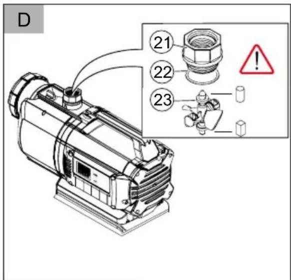
| 21 | Screw-in nipple |
| 22 | Seal |
| 23 | Measuring unit float body |
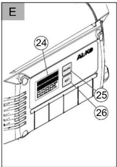
| 24 | Display |
| 25 | MODE button |
| 26 | SET button |
Designated use
The unit is intended for private use in the house and garden, and is exclusively suited to pumping clean water and rainwater.
It is suitable for:
Watering the garden and premises
Water supply in the house
Pressure increase in the water supply.

If the pressure of the water supply is increased, the local regulations must be observed. Your sanitation expert will provide the necessary information.
Possible misuse
The house water system is not suitable for the conveying:
Water containing sand, salt water and waste water with textile and paper content
Aggressive, corrosive, explosive or fuming chemicals or liquids
Fluids above 35^

The unit is not allowed to be used for pumping water for use in food or beverages.
The unit is not suitable for continuous use.
SCOPE OF DELIVERY
The unit is supplied ready for operation, with key for filter cover, elbow nipple and operating instructions.
Function
The described unit is an automatically working pump. The pump switches itself on and off according to the pressure (see technical data). When a draw-off point is opened, the pump draws in water through the pump inlet (7) and pumps it through the pressure line connection (4) to the draw-off point.
The pump switches itself off automatically about 20 seconds after the draw-off point is closed.
Thermal protection
The unit is fitted with a thermal protection switch which switches the motor off in the event of overheating. The pump switches on again automatically after a cooling down period of approx. 15 - 20 minutes.
Dry-run protection
The unit is provided with dry-run protection. The dry-run protection switches the pump off after about 90 seconds if water is not being drawn up or if the suction line is damaged.
Pressure sensor
The unit is provided with a pressure sensor. This sensor automatically switches the pump off and on.
Display indicator
For displaying the operational conditions and fault messages, the unit is equipped with a display (Fig. E-24). With the MODE button (E-25) you can select various different settings and displays and confirm with the SET button (-26).
SAFETY INSTRUCTIONS

CAUTION!
Risk of injury!
Use the machine and the extension cable only in perfect working order. Damaged equipment may not be operated. Do not disable safety and protective devices!
Children, or people who are not familiar with the operating instructions, are not allowed to use the machine.
Never lift, transport or suspend the unit using the connection cable.
Unilateral modifications or conversions of the unit are prohibited.
Electrical safety

CAUTION!
Danger when touching voltage conducting parts!
Disconnect the plug from the mains if the extension cable is damaged or severed! We recommend connecting a RCD (residual current operated device) having a nominal residual current of < 30mA .
The pump may not be operated while people are in the pool or pond.
The house mains voltage must agree with the details quoted in the technical data, do not use any other supply voltage.
The unit must only be operated with an electrical installation in accordance with DIN/VDE 0100, Part 737, 738 and 702. Protection must be provided by a 10 A line protection switch and a RCCD (residual current operated device) having a nominal residual current of 10/30mA .
Use only extension cables that are suitable for use outdoors - minimum cross-section 1.5 mm². Cable drums should always be unrolled completely.
Damaged or brittle extension cables must not be used.
Check the condition of your extension cable each time you start to use the equipment.
ASSEMBLY

CAUTION!
The unit will not function correctly if the draw-off point is 15m higher than the unit.
Erect the unit
- Prepare a flat solid area for erection.
- Erect the unit horizontally and where it will not be flooded.
The unit must be protected from the rain and direct water jet impingement.

In day-to-day operation (automatic mode) you must take measures to exclude the possibility that flooding of the room occurs as a result of malfunctions on the unit.
Connect the suction line
- Select the length of the suction line (Fig. B -14) so that the house water system cannot run dry. The suction line must always be at least 30~cm under the surface of the water.
- Connect the suction line. Make sure that the connection does not leak, without damaging the thread.
We recommend using flexible hoses at the pump inlet (Fig. A-10). This prevents mechanical tension or pressure from being exerted on the house water system.
- Always lay the suction line with an uphill gradient.

If the suction height is more than 4m you must use a suction hose having a diameter greater than 1". We recommend the use of an AL-KO suction unit with suction hose, suction filter and flow-back stop. Ask your expert dealer.
Fitting the pressure line
- Screw the connecting nipple (Fig. B -12) with the round seal ring (Fig. B -13) into the pump outlet (Fig. A -4).
- Screw the elbow nipple (Fig. B -10) with seal (Fig. B -11) onto the connecting nipple (Fig. B -12) and turn the elbow nipple in the desired direction.
- Fix a pressure line (Fig. B -8) onto the elbow nipple (Fig. B -10).
STARTUP

On initial commissioning the display (Fig. E-24) shows all information in English. Select the desired language with the MODE button (-25) and confirm with the SET button (-26).
Filling the unit

CAUTION!
Dry running will destroy the pump! The pump must be filled with water up to the overflow before each use so that it can draw water immediately.
- Open the filling screw (Fig. A -3) with the filter key.
- Fill with water via the filling screw until the marl on the pump housing is reached.
- Screw the filling screw back in position.

In order to reduce the suction time, fill the suction hose with water before screwing in position.
Initial start-up of the unit
- Open a closing-off device (valve, spray nozzle, water tap) in the pressure line.
- Insert the mains plug on the connection cable into the plug socket.
The pumps starts to pump.
- When no more air comes out with the water, close the closing off device in the pressure line.
The pump switches off when the flow stops, after building up pressure.
The domestic water pump is ready for operation. The display shows AUTO O and FLOW O.
Operation
- Take the unit into operation as described (initial start-up of the unit).
The domestic water pump is electronically controlled and operates fully automatically after initial start-up.
- The pump switches on when water is drawn off at the pressure side. The display shows ON X and PRESSURE as well as the actual pressure.

If no water has been drawn in through the suction line within 20 seconds, the pump switches to a checking mode. In this, the pump continues to run and the display shows CHECK SUCTION SIDE.

If no water is drawn in via the suction line (Fig. B-14) in approx. 90 seconds, the dry-run protection switches off the pump, and the display shows ALARM and SUCTION SIDE. Troubleshooting and fault rectification, see Help in case of malfunctions.

If the pump switches on and off frequently although no water is being drawn off, the pump will switch itself off to protect against overheating and the display shows ALARM and PRESSURE SIDE. Troubleshooting and fault rectification, see Help in case of malfunctions.
Switching the pump off
- Remove the mains plug from the plug socket.
- Close the closing off devices (valves, spray nozzles, water tap) in the pressure line.

CAUTION!
Danger of injury from hot water
In extended use against the closed pressure side (>10min.) ,the water in the pump can be severely heated up and can be emitted in an uncontrolled manner! Isolate the unit from the mains and allow the pump and water to cool down. Start the unit again only after all the faults have been rectified!
The risk of injury from hot water can arise if:
the installation is not correct
the pressure side is closed off
there is a lack of water in the suction line, or if
the pressure switch is defective.
Procedure
- Isolate the unit from the mains and allow the pump and water to cool down.
- Check the unit, the installation and water level.
- Start the unit again only after all the faults have been rectified!
MAINTENANCE AND CARE

CAUTION!
The pump must be isolated from the mains before any maintenance and service work. Remove the mains plug from the plug socket.
Flushing the pump
After conveying swimming pool water containing chlorine or fluids that leave a residue the pump must be flushed out with clear water.
Cleaning the filter
- Unscrew the drain screw filter chamber (Fig. A-6) of the draining opening, drain the filter chamber and close the draining opening again.
- Clear filter cover (Fig. A -1) using the filter key (Fig. C -15/D).
- Remove the filter (Fig. C-16/C-17) from the filter housing (Fig. A-2) and clean under flowing water.
- Cleaning the filter housing and clear sight filter cover.
- Before fitting the filter, check the filter seal (Fig. C-16) and the housing seal (Fig. C-20) for damage, and replace if necessary.
- Fit the filter, screw the filter clear sight cover in place and tighten hand-tight with the filter key.
Cleaning the check valve
- Removing and fitting the filter (see Section "Cleaning the Filter").
- Check valve (Fig. C-18) and clean under flowing water.
- Replace seal (Fig. C-19) if necessary.
- Fit check valve.
Unscrew float body
- Pressure line (Fig. B -8) with elbow nipple (Fig. B -10) and connecting nipple (Fig. B -12) must be unscrewed.
- Unscrew screw-in nipple (Fig. D-21) with seal (Fig. D-22). Note the fitting position of the float body (Fig. D-23). Pull out the float body and clean it.
- Replace the float body - note fitting position (Fig. D).
Remove blockages
- Isolate the unit from the mains and secure against switching on again.
- Remove the suction hose from pump inlet.
-
Connect the pressure hose to the water supply.
-
Allow water to run through the pump housing until the blockage is removed.
- Check that the pump is running freely by switching it on briefly.
- Start the house water system again as described.
STORAGE

If there is a risk of frost, the entire system must be drained (pump, lines, storage vessel and filter chamber).
- Drain the suction line (Fig. B -14) and the pressure line (Fig. B -8).
- Unscrew the drain screws (Fig. A-6/A-6a) and allow the water to flow out of the pump.
- Screw the drain screws (Fig. A -6/A-6a) back in position and store the pump, lines and storage vessel in a frost-free environment.
DISPLAY INDICATIONS
On initial commissioning, all information appears on the display in English.
All functions can be called up using the MODE button. The displays/functions called up are confirmed with the SET button.

The information in the second line of the display is partially shown as running text which provides running information continuously.
Normal operation and additional functions
Setting the language
Display indicator Switching condition Function / actions
Pump running or switched off
Press the MODE button for longer than 3 seconds, the operating language is activated. Change the operating language by pressing the MODE button (30). Confirm the new operating language by pressing the SET button.
Initial start-up of the unit
Display indicator Switching condition Function / actions
Pump ready Pump starts automatically when water is drawn off.
Pump runs in normal operation
Display indicator Switching condition Function / actions
Pump runs in normal operation
| ON X PRESSURE MODE2.0 BAR SET | Pump is switched on and is pumping water.⇒ Pressure is displayed. | |
| ON XMODEFLOW3300 L/HSET | Pump is switched on and is pumping water.⇒ Pressure is displayed. | |
| Rotating X after ON symbolises pump is ON | ||
Pump in automatic mode, not pumping
Display indicator Switching condition Function / actions
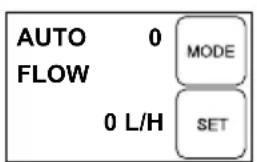
| AUTO 0 FLOW MODE 0 L/H SET | Pump is switched on but is not pumping water. ⇒ No through-flow; 0 l/h is displayed. | Pump starts automatically when pressure line is opened (valves, spray nozzles, water tap, etc.). |
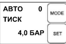
| AUTO 0 PRESSURE MODE 4.0 BAR SET | Pump is switched on but is not pumping water. ⇒ Pressure is displayed. | Pump starts automatically when pressure line is opened (valves, spray nozzles, water tap, etc.). |
| 0 after AUTO symbolises pump off | ||
Displaying flow rates
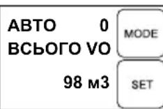
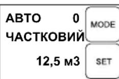
The following information can be displayed by pressing the MODE key both during operation (ON) and in AUTO status.
Display indicator Switching condition Function / actions
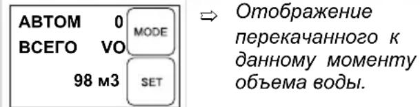
| AUTO 0 TOTAL VO 98 m3 MODE SET | ↔ Displays the volume of water already conveyed. | |
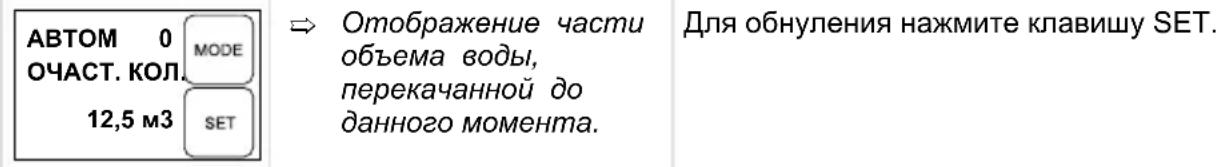
| AUTO 0 VOLUME SU 12.5 m3 MODE SET | ↔ Displays the volume of water already pumped. | Press the SET button to reset to zero. |
Press the MODE button to switch between displaying the pressure and through-flow as well as flow rate.
TROUBLESHOOTING

CAUTION!
Disconnect the mains plug before any fault rectification work. Faults in the electrical system must be rectified by a qualified electrician.
| Malfunction Cause Rectification | ||
| Pump drive motor does not run. | No mains power. Check fuses and power supply. | |
| CHECK SUCTION SI MODE 0.0 BAR SET | Pressure and through-flow are deviating from normal values, but pump is still running. | Message appears after 20 s. Pump attempts to rectify fault itself for 90 s. No action required. If fault persists after 90 s, pump switches off as dry-run protection. |
| ALARM SUCTION SI MODE 0.0 BAR SET | Pump is switched off as dry-run protection. | Fault on suction side. Rectify fault and press SET. Pump then starts up again. Attention: hot water when restart occurs. |
| Leak on suction side. Check suction valve and suction hose. | ||
| Leak on filter bowl. Check filter bowl seal, retighten filter bowl. | ||
| Leak on filter chamber drain screw. | Check drain screw seal, retighten drain screw. | |
| End of hose not in water, water reservoir (e.g. cistern or borehole) empty. Pump drawing in air. | Suction line must always be at least 30 cm under the surface of the water. | |
| Filter heavily contaminated. Clean filter. | ||
| Suction line blockage Remove dirt from the suction area. | ||
| Flow rate less than 300 l/h. Increase flow rate. | ||
| ALARM CHECK PRE MODE 1.5 BAR SET | Pump switches on and off several times although no water is being drawn off. → Pump is switched off as protection against overheating. | Fault on pressure side, e.g. leak. Even small leaks on water taps and toilets can cause the system pressure to drop. Check the pressure line and draw-off points for leaks. Check and clean the check valve (18) in the filter chamber. Rectify the fault and confirm with SET - pump then restarts. Attention: hot water when restart occurs! |

If the faults cannot be rectified, please contact our customer service department.
DISPOSAL
Do not dispose of worn-out machines or spent batteries (including rechargeable batteries) in domestic waste!
The packaging, machine and accessories are made from recyclable materials and must be disposed of accordingly.
WARRANTY
We will address claims for any defects in materials and workmanship during the statutory period of limitation by means of repairs or replacements of our choice. The period of limitation is governed by the laws of the country in which the machine was purchased.
Our warranty applies only if:
The machine has been properly handled
The operating instructions have been adhered to
Original replacement parts have been used
The warranty is no longer in effect if:
Efforts have been made to repair the machine
Technical modifications have been made to the machine
The machine has not been used for its intended purpose
The warranty does not cover:
Damage to paint work through normal use
Parts subject to wear as indicated in the replacement parts list with a box [xxx xxx (x)]
Internal combustion engines - separate warranty conditions of the respective engine manufacturers apply
The warranty period begins with the purchase by the first buyer. The warranty period begins on the date that appears on the original purchase receipt. In the event of a warranty claim, please your contact supplier or the nearest authorised customer service centre with this warranty declaration and the purchase receipt in hand. This warranty does not affect the legal warranty claims by the purchaser against the seller.
EU DECLARATION OF CONFORMITY
We hereby declare that this product in the version introduced into trade by us, complies with the requirements of the harmonised EU Directives, EU safety standards and the product-specific standards.
Product Type Manufacturer
Domestic water system
Serial number
G3043045
HwA 4000 comfort
HWA 4500 comfort
HWA 6000/5 Premium
AL-KO Geräte GmbH
Ichenhauser Str. 14
D-89359Kotz
Duly authorised person EU Directives Harmonised standards
Andreas Hedrich
Ichenhauser Str. 14
D-89359Kotz
Kotz, 19.01.2016

Wolfgang Hergeth
Managing Director
2014/35/EU
2014/30/EU
2000/14/EU (13)
2011/65/EU
Sound pressure level
EN ISO 3744
HWA 4000 comfort
measured: 80 dB(A)
guaranteed: 82 dB(A)
HWA 4500 comfort
measured: 81 dB(A)
guaranteed: 83 dB(A)
HWA 6000/5 Premium
measured: 73 dB(A)
guaranteed: 75 dB(A)
EN 60335-1:2012
EN 60335-2-41:2012
EN 62233:2008
EN 55014-1:2012
EN 55014-2:2016
EN 61000-3-2:2014
EN 61000-3-3:2014

2015
Conformity evaluation
2000/14/EC Appendix V
VERTALING VAN DE ORIGINELE GEBRUIKERSHANDLEIDING
Inhoudsopgave
INFORMATIONS SUR CE MANUEL
Se先进技术 non sono in situ. In fact, the proposed algorithm is based on a combination of two techniques: (1) a priori optimization problem, (2) a stochastic gradient descent procedure. The latter is used to solve the optimization problem.

SCHEDA RICERCA GUASTI

CAUTELA!!
2000/14/ES, priloga V
PRIJEVOD ORIGINALNIH UPUTA ZA UPORABU
Kazalo
Uzovajpriručnik. 72
Opis proizvoda. 72
Opseg isporuke 73
Sigurnosne napomene. 73
Montaža. 73
Pušanje u rad. 74
DEKLARACJA ZGODNOSCI WE
Pumpen begyinner a transportere.
VEDLIKEHOLD OG PLEIE

OBS!
2000/14/EF tillegg V
ALKUPERAISEN KAYTTOOHJEEN KÄANNÖS
Sisallysluettelo
Wolfgang Hergeth Managing Director
Aänitehotaso
EN ISO 3744
HWA 4000 comfort
mitatu: 80 dB(A)
taattu: 82 dB(A)
HWA 4500 comfort
mitatu: 81 dB(A)
taattu: 83 dB(A)
HWA 6000/5 Premium
mitatu: 73 dB(A)
taattu: 75 (dB(A))

2015
Vaatimustenmukai
suuden arviointi
2000/14/EY liite V
TOLGE ORIGINAALKASUTUSJUHENDIST
Sisukord
Kasiraamat. 146
Tootekirjeldus. 146
Tarnitav varustus. 147
Ohutusjuhised. 147
Kokkupanek 147
Commissioning. 148
Tanımlanan cihazda otomatik calişan bir pompa soz konusudur. Pompa basinca®,®,®,®,®,®,®,®,®,®,®,®,®,®,®,®,®,®,®,®,®,®,®,®,®,®,®,®,®,®,®,®,®,®,®,®,®,®,®,®,®,®,®,®,®,®,®,®,®,®,®,®,®,®,®,®,®,®,®,®,®,®,®,®,®,®,®,®,®,®,®,®,®,®,®,®,®,®,®,®,®,®,®,®,®,®,®,®,®,®,®,®,®,®,®,®,®,®,®,®,®. Çekme yeri açilirsa, pompa suyu pompa girişi (7) üzerinden emer ve basinç hatti baglantisi (4) üzerinden Çekme yerine aktarir.
YcTpoIcTBo IpeHa3HaueHo IJn YacTHOrO
NcNoJIb3OBAHnB DOME N CaDy N paCCHTaHO
NCKIOUHTeJIbHO Ha OCBeTTJeHHyIO N DOXKeByIO
BOdy.
OHO IOxOJNTnA:
Длгполива сада и учacстka;
BOOCha6xKeHnI Doma;
NOBblIeHnHaNoPa BObl B BOdOnpOBoJe.

Pn NOBbIeHn DaBHeHn B BOOpnoBoNe Heo6XoDmO co6nOdaTb PpeNtcaHn MeCTHO 3aKoHOaTeNbCTBa. HΦopMauIO MOxHNOJnyHTb OT CneuaJIncTa nO caHTexHueckOMy OobpydoBaHIO.
Cnyan HnpaBnIbHoro npImeHeHna
Domaunna Hacocha cTaHnne He npedHa3NaeHa nna noa:
BOdbI C NeCKOM, COJeHOB BOdbI IN rpa3HOI BOdbI C BkJIIOUeHnAIM TkaHN 6ymaH;
arpeccnBbIX, eKNX, B3pbIOONaChbIX NIN BblJeJLOUx Ra3bl XIMNueCKNX BeIeCTB ININ KNDKOCTeI.
KnDkoTeC TeMpepatypoB 6Ooe 35^

YcTpoIcTBO He CneIyET NcNoJIb3OBAtB
IINaIOaH BODbl IINpOdyKTOB
NITAHIN HAHTKOB.
YcTpoIcTBo He paccuHaHO Ha HnpepbIBHyO pa60Ty.
KOMJIeKT NOCTABKN
YCTPOCTBO NOCTABLARETCB ROTOBOM K ФКСПУATAUIN COCTOHRN C KIHOUM ДЯ КрБИКИ ФИNBТР, YRTOBIM HINPEJEM I pyKOBODCTBOM NO 3KCPNYATAUIN.
PnHnIeIcTBna
OnncbIbAeMOe ycTpoNCTBO npedctabJraet cobO bATOMaTHueckn HAcoc. HAcoc BKnIOuaeTc n BBkIIIOuHaTeCBA 3aBNCIMoCTn OT DaBHeHna (CM. TexHnueckne XapaKTepnCTnKn). Pp n OTKpbITn ToKn 3a6opa Hacoc BCacbIBaET Body uepe3 BXoD (7) n nepeKaunBaet ee uepe3 pa3bem HanopHOJ nnHn (4) K TOUKe 3a6opa.
Hacoc aBTOMaTnueeKn BbIKJIouHaETcra npM. uepe3 20 c nocne 3akpbITna TOOKn 3a6opa.
Tennobaa3aunTa
YcTpoCTBO OCHaUeHO 3aUHTbIM TepMopeJe, OTKIOUaIOUm HAcOC pRn nepepeBe. Nocne nepNoDa OXJaXDeHnI PpOJXtJIbHOCTbIO 15-20 MInHyT HAcOC aBTOMaTueeCKN BkIIOuHaETcra.
CnCTema 3aunltbIOT cyxoro xoda
YcTpoNCTBO OCHaUeHO CnCTeMoN 3aUHTbI OT cyxoro XoJa. EcIn BOJa He BCacbIBaETCa
IINIOBpeXdeH BCacbIBaIOUmN Tpy6OpBOoD, CnCTema 3aunTbI OT cyxoro XOda BbIKIOuHaET HAcoc Yepe3 90 cekyHd.
DaTyn daBneHna
YcTpoIcTBO OCHaUeHO DaTNUKOM DaBJIeHnA. C NOMOuIbIO 3TOrO DaTNUKa HAcOC aBTOMaTHueCKN BKIIuOuaeTCra N BbIKIuOuaeTCra.
HdkauHa ducnlee
YCTPOINCTBO OCHaSeHOn DnCnJIeem (puc. E -24)ДЯ OTO6paXeHnpeKIMoB pa6Otbl n coo6uHnOB oWn6kax.C NOMOuBIO KnaBnIIMODE (E-25)MOxHO BbIbnpaTb pa3HbIe HAcTPOIKN IN peKIMbI INDnKaUH, a C NOMOuBIO KnaBnIIN SET (-26)NoDTBePckDaTb BbIbOp.
YKA3AHNIO B6E3ONACHOCTN

BHIMAHNE!
Onachoctb TpaBMnpoBaHn!
NcnoJb3yIte yCTpoINCTBO TOJIbKO B TEXHnueCKN NCnPpABHom COCTOHN.
3anpeaetcnaKcnnyatnpoBaTb NOBpeKdEHHbIe yCTpoNCTBa.
3aPpeaetcBbIBOHTb 3CTPO npedoxpaHntbHbIe 3aHTbIyctpoiCTBa!
I DeTn n IINuA, He O3HaKOMJIeHHbIe C HNCTpyKcIeN IO 3KcIIyatauN, He DOJXHbI NCIOJIb3OBaTb yCTPOIcTBO.
He noHnMaIte He noBWeuBaIte yCTPOcTB0 3a 3JIeKtpueckn Ka6eNb, He TAHITe 3a Hero npn nepMeueHn yCTPOcTBa.
3aPpeaetcay cMOBOJbHO BHOCHTb n3MeHEnB yCTPOIcTBO n nepeo6OpydoBaTb erO.
3JIeKtpnuecka 6e3onacHocTB

BHIMAHHE!
Onachoctb npn npNKOCHOBeHHK Yactm, HaxOJaUIMcra HapjXeHHeM!
Pn NOBpeKdEHN ydHnHTeJbHOro Ka6e np3 pO3eTKn! PekomeHdyem NODKNIOUaTb ycTPOINCTBO yepe3 ycTPOINCTBO 3aunTHORO OTKIOUyeHNA, cpa6aTBBAIOOee npn HOMHaJIbHOM Toke yTeKN < 30 mA.
KordaB6acceneHnncaOBOm npdy HaxoTcJIOHn,HaocHe DoJxeh pa6oTaTb.
HanpajkeHne B cetn Doma DoJxHo COOTBeTCTBOBaTb HapjxKeHIO, yKa3aHHOMy B TexHnuecknx XapaKTePncTnKax; He NOdknOuayTe yCTpoNcTBO K nCTOuHNky C dpyrHM HanpajkeHneM.
UcTpoiCTBO MOXHO HcNOJIb3OBAbToJIbKO B 3JIeKTPnuecko CnCTeMe,OTBeuAIOSei DIN/ VDE0100,YacTb737,738n702.DIy o6ecneHnra 3aUNtblHyxHO yCTaHOBnTB IINHeHbIMaHTbI aBTOMaT 10A,a TaKKe yCTpOiCTBO 3aUNTHoro OTKIIIOUeHnRA cpaBaTbIBaIOUeep npHOMHaJIbHOM TOke yTeuKn 10/30 mA.
IcnoJb3yInTe TOnbKO yDnHnTeJI, paCCHTaHHbIe Ha ICNoJIb3OBaHne BHe NOMEuHn, C MHNMaJIbHbIM CeYeHnEM 1,5 MM². Bcerda noJIHoCTbIO pa3MaTbIbAitKe Ka6eJIbHbIe KaTyuKn.
3anpeaetcnaCnOJb3OBaTb NOBpeKdEHHbIe NJI INOMKHe yDnHHTeNbHbIe Ka6eIi.
Npeed kaxkbim nyckom npoeepaume coemnHue yduhumeNbHO20 Kaebna.
MOHTAK

BHIMAHNE!
YcTpoIcTBo pa6OtaeT He HauJIexaUIM o6pa3OM, ecn TOnKa 3a6opapacnoJIOKeHa Ha 15 M BbIe Hero.
YctaHOBka yCTpOINCTBa
- PoiToTOBbTe poBHyIO n TBepDyIO NOBepXHOCTb.
2.YctaHOBnTe yCTPOINCTBO TOpN3OHTaNbHO B 3aUHcEHOMOT3aTOnJIeHnM MeCTe.
Ycmpoucmeo doJxHo 6bim3aUuueHo omdojraunpmao nonadahnrcmpyu 60dbI.

Pn exeHBeBHOJ 3KcNpyaTcuu (aBTOMaTHueckn peXIM) C NOMOUB COOTBETCTByUoIHX MEP Heo6xOIMO NO3a60NTbCRA O TOM, YTO6bl Pn HEnCnpaBHOCTNuCTPOINCTBa He Ipon30UINO 3aTOnJIeHHe NOMEUeHN.
IopKnIOueHHe BCacbIBaHOe JINHH
- BbIbePte DnHy BCaCbIBaIOJero Tpy6oPoBOda (puc. B-14) TaK, YTO6bI NCKJIIOHTb pa6Oy DomaUHei HACOCHO CTAHUN BCYXUY. BcAcBIAIOUH Tpy6oPoBOd BCEJa DOJXeH 6bITb NorpyKeH B BOdy He MeHee Yem Ha 30 cm.
2.ПодсоeннTe BCacbIbAIOUуTO JINHnO.Iprn 3TOM CJIeDHTe 3a REpMeTNUHOCtBIO N 3a TeM, YTO6bl He NOBpeDNTb pe3b6y.
Ha exode hacoca pekomeHdyem ucnoIb306amb 2u6Kue uHaH2U (puA-7).Ppu 3mom domaun Hacochar cmaHcua He nOdeep2aemcra daBHeHuU mraOeBM Haapy3kam.
3.Bcerda npoklaadbBaIte BCacbBaHOyU JINHIO C NODbEMOM.

Pn BbICote BCacbBaHn 6OJee 4 M, Heo6xOIMO yCTaHOBnTb BCacbBAHOuN m JIahr C dHaMeTpOM 6OJee 1 IIOIma. PekomeHyem nCNOb3OBaTb rapHtpy AL-KO C BCacbBaHOUm WJAnHROM, BCacbBAHOUm FInbTpOM N KJaNaHOM DnI ppeDToBpaUeHn O6paTHoro Toka. O6paTntecb 3a KOHCyJIbTaUcnei K CBOeMy dIJIepy.
MOHTaK HAnOpHOn JInHn
- BbHTnte coeHHTeBHyI HnNneB (puc. B-12) cyNtHTeBHBIM KObUOM KpyrIoro ceueHna (puc. B-13) B bIXoHoe OTBepCTne Hacoca (puc. A-4).
- HABHNTTE yrJIOBOH HnIeNb (puc. B-10)c yIIOHTHeHnEM (puc.B-11) Ha coeHNHTeJIbHbI HnIeNb (puc.B-12) n NOBepHNTe yrJIOBOH HnIeNb B HyxHOM HappaBHeHH.
- 3aKepeHnTe HAnOpHbI Tpy6oPBOoD (puc. B-8) Ha yrnoBOM Hnnpene (puc. B-10).
BBOB 3KcIJIYATAUHIO

Iprn nepbohaayabHom nycke B 3KcnpnyatauHO BcNOpMaun Ha dncnnee (puc. E-24) oTo6pa3ntcHa aHrnnckom y3bike. Bbl6epTe Hxhbln r3bIK c nOmoUBO KnaBnUI MODE (-25) INoTBePdnte HaxaTneM Ha KnaBnuy SET (-26).
3anonHeHne yctpoicTba

BHIMAHNE!
Cyxoi XOD npINBOIDNT K BbIXOHy hacoca n3 cTpo! Npeed KaKdbIM cnUyAEM NCNOJb3OBAHnHaCOC HyXHO ONHOCTBIO 3aONJHrTb BOOn, YTO6bl OH cpa3y Je MoI HaAtb IpOcecc BCacBBAHN.
- OtkpoTe pe3b6OByIO npo6ky HaNIBHOrO OTBepCTnA (puc.A-3) c nOMOuBu KInOua dIa CHrTnA FnIbTpTa.
- 3aHbAte Yepe3 pe3b6OByo npo6ky HAnBHO OTBepCTn BODy Do Tex nop, NOKa ee ypoBeHb He DoiDeT Do OTMeTKn Ha Kopnyce Hacoca.
- Choba 3aBepHnte pe3b6ObyIO npo6ky HAIINBHOrO OTBepCTnI.

Для сokpaшеня Врemeи BCacbIbAHn 3anONHte BCacbIBaUuM WJaHr Nepei HabINHcYBaHm BODoI.
IepBbI BBOy yCTpoiCTBa B 3KcNpyaTauIO
- OtkpoTe 3anop HanopHoi JInHn (KnaHa, fOpcyHky, BOOnpOBoHbI KpaH).
2.Bctabte Te TKepe Ka6eJn dna ceTeBOro noKJIoueHn B po3eTKy.
Hacoc HaHem nepekaueamb60dy.
- Korda B BbITEkaUoSei n3 Hacoca BoDe He OCTaHETcB O3dyxa, 3akpoTe 3anOpHoeyCTpOietBO B HAnOpHOM Tpy6onpOBoJe.
Ppu omcymcmbeuu nomoka nocne yeenueHua daaeneHua Hacoc aemomamueecku omknioyaemca.
Домашни насочьиaelomam zomoe κ paбOME. Ha duçпee omobpaхаюмся haonucu ABTO u NOTOK O.
Pa6ota
- BBeDnTe yCTpoIcTBO B 3Kcnnyatauio corlacho onncahIO (cm. pa3delen «PepBbI BBOD yCTPOIcTBa B 3Kcnnyatauio»).
Domaunu Haocn b aemomam peaynpyemc c nOMoou 3neKmpoHuk u nocne nepe020 6eoda e 3kcnnyamauio pa6omaem aemomamuuecku.
2.ПрзаборевдыссторныHarHeТаньпронсховиВКлюченинacoca.HaДиспjee OTo6paЖаIOТсЯнDCNnBКЛXиДABJIЕHNE,aTakke3naueHneФakTNueckoro daBJIeHnI.

Ecnn uepe3 20 c He npOncxOoNT BCacbIBaHne BOdbI uepe3 BCacbIBaHcN Tpy6OpBOOD, Hacoc nepeKnUoyaeTcra Ha KOHTpObln pexim. Ppi 3tOM Hacoc npoDOnXaet pa6oTaTb, Ha DnCnlee oTo6paXaETcra HaanCb IPOBEPbTE CTOPOHY BCACbIBAHJr.

Ecnn uepe3 90 cekynd BO BCacbIBaIOUm Tpy6oNpOBoD (puC. B-14) He 3aKaunBaETcR BODa, CnCTema 3aUNTbl OT cyXoro XoJa OTKnIOHT HAcOC,a Ha DnCnIe BbICBeTntc TPEBOA n CTOPOA BCACbIBAHNIA. POnck N yctpaHHe HeNCnpaBHOtei: CM. pa3dJI «YcTaPaeHne HeNCnpaBHOtei>.

Ecnn Hacoc yacto Bknoaetcny BBIOUcaETcra HO npn 3TOM 3abop BObl He npocxOINT, dIpypeDOrbpaueHneperpeBa Hacoc BbIKNouaETcra,Ha DnCnlee OTObpaKaHOCT HaDnnc TPEBOA n CTOPOHA HAHETAHNIA. Pnunhbl n ycTaPHeHne HncnpaBHOCTe: CM. pa3dJe «UcTpaHHeHne HncnpaBHOCTeR
OTKJIHoueHne Hacoca
- BbInbTe WTeKep n3 po3eTKn.
- 3aKpoIte IMeIoUeIeB HAnOpHoi JInHn 3aOpHbIe yCTpOJcTBA (KnanaH, fOpcyNky, BOIOnpoBOdHbIK paH).

BHIMAHHE!
Yrpo3a noJyueHnra TpaBM ot ropyeB BOdbl
Pn dInTeBHO pa6oTe c 3aKpbIToH HAnOpHO CTOpOH (>10 MHN.) BODa B HAcOe MOKeT CNbHO HarpeTbCra, TaK UTO Ipon3OJET ee HeKOHTpONIPyEMOE BBTEKaHHe! OTKJIOnHTe yCTpoINCTBO OT CetN n DaTe BOe N HaOCcy OCTbTb. NobTopHO nCNOJB3OBAHne HAcoca BO3MOxHO ToJIbKO NocJe yCTpaHEHnB CEx DepeKToB!
Yrpo3a noJyueHn TpaBM OT ropyeB OdbI MOKeT BO3HNKHyTb:
PnHEnpaBnBHOyycTaHOBKe;
3akpbIToH HAnOpHO CTOpOHe;
HeIOCTaTOHOM KOINueCTBe BObI BO BCaCbIBaHOUeJINHN;
HEnCnpaBHom KHONoCHOM NepeKJIouaTeJe.
Heo6xOaMbIe JeIcTBnA
- OTKJIIOUHTe yCTPOIcTBO OT cETn I daIte BoJe HAcOCy OCTbITb.
2.Поберпусговь MOHTAXИ ypoBeHb BOДbl. - NOBTOPHOE IcNoIb3OBaHne HAcoca BO3MOxHO TOnbKO NocNe yCTpaHeHnB BCEX DepeKToB!
TEXOBCJYXKUBAHNE UYOXI

BHIMAHNE!
IpeHnauHm IIO6bIX pa6OT nO Texo6cJyXkBaHnIO n peMOHTy Hacoc Heo6xOaIMO OTKJIIOuHTb OT cETN. BbInbTe WTeKeP n3 po3eTKn.
PpombbKa hacoca
Iocne nepekaunBaHncaOpXnOp BObI n3 baccenHa nn JxndKoCTe, OCTaBJIIOxN HaneT, HAcOC Heo6XoIMO IpomBaTb YnCTOn BDOJ.
OuicTkka qHnbTpa
- OTKpoIte pe3b6Obyo npO6ky cInBHOro OTBepCTnKaMepblΦnIbTpa, (puc.A-6) ONOPOXHITe KaMepyΦnIbTpau n CHOba 3aKpoIte CInBHOe OTBepCTne.
- Otkpytnte npo3paHnyo KpbIuKy fNbTpap (puc.A-1)c nOMOuKIO KIOUa dIra CHrTna fNlbTpap (puc.C-15/D).
- Φильтpr (puc. C -16/C-17) n3BneKeNTe n3 kOpnyca Фильстрpa (puc. A-2) n npomOnTe erO B npotoUHOBdE.
- OuInCTnTe Kopnyc ФиЛьТра n npO3paHHyIO KpbIshKyФиЛьТра.
- Перед установский Фньтра поверты улочене Фньтра (puc. C-16) и улочене корпуca (puc. C-20) на начные NOВраздени, ри HeoбхODIMOCТИ 3amehnte.
- YctaHOBnTe nIbTp, HABHHTnTe npO3paHyIO KpbIuKy nIbTp a N 3aTnHnTe ee C NOMoUbIO KNIOHa DnA nIbTp a.
Ouictka o6paTHoro kJanaHa
- ChTne n yctaHObKa unIbTp a (cm. pa3deJ «Oucmka unbmpa').
- BbInHTte o6paTHbI KlaHn (puc. C-18) n npOMoIte eO B npToUHO BOE.
- YnnotHeHne (puc. C-19) npn Heo6xoDnMoCTn 3aMeHNTe.
- YctahOBte 6paTHbI KJIanaH
NonJaBok
- Bbikpynte HanoHbI TpyboPoBOD (puc.B -8)c yrnoBbIM HnPiNeM (puc.B-10) n c coeHNHTeNbHbIM HnPiNeM (puc.B-12).
- BbINHTTE BBHNUBAIOUncra HnnpneJIb (puc. D-21) cyNtOHHeM (puc. D-22). 3aMeTbTe, B KaKOM NIOXKeHH yCTaHOBJIeH NONIaBOK (puc. D-23). BbIHbTe nonIaBOK n OuNCHTte erO.
- Choba yctaHOBNTe nonnaBOK c yyeTOM ero MOHTaXHOrO nNoXKeHnR (puc. D).
YctpaHHe 3acopoB
- OToCoeHnHTe yCTpoIcTBO OT cETn I npEdoXpaHnTe erO OT NOBTOpHOrOBKJIouyeHnJ.
- OToCoeHNHHe BCaCbIBaIOUm IuaHr OT BXoHOrO OTBepCTnHaCOca.
3.ПодключITE HANOPHBI WJNAHr K BOДОПВОБODY. - Boda donjxHa npoteKaTb uee3 Kopnyc Hacoca, noka He 6ydt yctpaHeH 3acop.
- KopoTkIM BKNIOUeHnEM npOBepbTe cbo6oJHOe BpaueHne Hacoca.
- CHOBa 3aIyCTnTe yCTpOInCTBO COOTBeTCTBnC INHCTpyKUnei.
XPAHEHNE

IpyyHIOHOIOPOXHTb (HaCOC, Tpy6oPBOOdbI, HApOpHbI 6aK n KaMepy fNJIbTpa).
- CneIte Bovy n3 BCacbIbAIOUeRo (puc.B-14) n HAnOpHoro Tpy6oNpOBoIOB (puc.B-8).
- BbIkpTynte pe3b6OByIO npo6ky cIINBHO OITBePCTN KAmepblΦnJIbTpap (puC.A-6/A-6a) I daHTe BODe BbITEyH3 Hacocca.
- Choba 3aKpyTnte pe3b6obBie npo6Kn CnVBhIX OTBepCTn (puc. A-6/A-6a) n pa3MeCTnte Hacoc, Tpy6oPBOdBi N HanOpHbI 6ak Ha xpaHeHne B 3aunueHHOM OT MOpO3a MeCTe.
HДИКAUЯHAДИСПЛЕ
Pn nepBOHaayabHom nycBe B 3KcNpyaTuH BCa INHOpMaun Ha dncnnee OTo6paxKaetc H aHrnnckom r3bke.
Bce cyHKun MOxHo Bb3bBaTb c NOMOu bKnaBnH MODE. Bbl3OB HndkaTopoB/ychkui noTBePckdaetcnaKaTneM KnaBnH SET.

YacTb OTo6paKaemO BTOPOI CTOPOE DnCnpe HnΦopMaqun NMeET BnD 6erye CTPOKn, B KOTOPoHnpepbIBHO OTo6paKaetc HnΦopMaqun.
HopmaJIbHbI peKIM pa6oTbI n DonoJHnTeJIbHbIe cyHKcN
HacTpoIka J3bIka
| Инданацая на дисп lee | Соspectные пereкlioочnersу Фунkedия/мерbl | |
| PyCCKIMODESET | Hacoc pa60taet ил hyacoc otКюочen | HajimaTe knaBshy MODE 6oJee 3 seKynd, aktNBpyeTcraЯЗБК Иnterpфсйca. HaxaTneM knaBShn MODE (30) можно ИзMeHITь яЗБК Иnterpфсйca. ПобТВердNTe HOВьй яЗБК Иnterpфсйca haxaTneM na KnaBshy SET. |
IepBbI BBOy yCTPOiCTBa B 3KcNlyaTaunIO
Haoc B aBTOMaTnueckom pexime, He kaJaet
Hdkaunippon3BODHTeJIbHOCTn
CJIeIyUOuI INHOpMaUIO MOXHO BbIEcTn IyTeM HaxaTnaKJIaBUNI MODE KaB pexIme pa6oTbI (BKJI), TaK n B COCTOHN ABTO.
HndkaunHa CoCToHne nepeKluOeHnA FyHKnIa/MepbI dncnnee
IpeeknueHne MeJdy Hndnkatopom daBHeHna npacXoJa, a TaKke HndnkatopamnpOn3BOIndTeNbHOCTN ocUeCTBnAeTcra c nomOu bIO KnaBnM MODE.
YCTPAHEHNE HENCINPABHOCTE

BHIMAHNE!
Ipeed IIO6bIMn pa6oTAMN IO yCTpaHEnIO HeNCpPaBHOCTe BbIHMaIte n3 PO3eTKn ceTeBOJ Ka6JIb. HeNCpPaBHOCTn 3JeKTPoCnCTeMbI DOJXHbI yCTpaHrTb IpOpeCCNOHaJIbHbIE 3JeKTPnKn.
HecnpapBHOctb PnpuHa CnocO6bl yctpaHEna
PnBODHOJ DBNrTaTeNb Hacoca He pa6oTaet.
EcnHnCnpaBnocb He ydaetc yctpaHnTb, obaaatcB hauy cepBncHyo clyk6y.
YTNJIIN3AUIN
BbIeDnne n3 cTpo np6Opbl, aKkymyIaTOpbI n 6aTapeu 3aPpeaTeC yTnIn3HpOBaTb BMeCTe C 6bITOBbIMN OTXoJam!
Инсту мent, erg yanaKobka n npinaJIeXHOCTn I3rOToBJIeHbI n3 MaTePnaIIOB,poIneXaIIx BTOpUHoi nepepa6oTke,poTOMy IX CJIeDyET yTINu3InPoBaTb COOTBeTCTByIoUIM 06pa30M.
TAPAHNTN
Ipon3BOJnteYyCTpaHReT BO3MOXHbI DeΦeKtBi MaTePnaIOB IINI pON3BOJcTBeHHbI 6paK yCTpoiCTBa B TeueHHe yCTaHOBJIeHHOrO 3aKOHOM CpOKIpaU PeKJaMauNHa CBOE yCMOTpeHne IyTeM peMOHTa IINI 3aMeHbI. CpOK ONpe- DeJIaETcRA 3aKOHOdAteJIbCTBOM CTpaHbI, B KOTOpO npNo6peTeHo yCTpoiCTBO.
TapaHTnI DeIcTByET TOnbKO npi CneDyIOuX ycNoFapAHTnI aHHynpyEcra
BnX:
I npn HauJnEkaUem nCnoJb3OBaHn yCTpoNCTBa;
Pn co6JIOJeHnn pyKOBOdCTBa no 3KcIpyatauIN
PnNcNoB3OBAHmOpuHaJIbHbIX3aNpacteI
PnNONbITkax pemOHTa yCTpoiCTBa
IpnTexHnuecknx N3MeHeHnX yCTpOInCTBa;
PnnpimHeHn He No Ha3HaueHnIO (HanpImep,B KOMMepuecknx ceJx).
Fapantna He pacnpocptpahreTc:
Ha NOBpeKdEHNJaKOBOrO NOKpbITnA, KOtOpbIe O6brcHJOTcH HOpMaJIbHbIM I3HOCOM;
n3HaUNBaIOUneCraTeaJIH, KOToPbIE B KaTaIOne 3aNuaCTeN 3aKJIuOHeHb B paMky [xxx xxx (x)]
DnBraTeJI BHyTppeHHeRo CrotapHna: Ha Hnx paCnpocTpaHryTCyCNOBna IpeOCTabNeHnra rapaHTmOT npOn3BO-DnteJIa
IapaHTnHbI nepnoHaunhaetcC daTbI npno6peTeHnepBbIM nOKyNaTeHem. TaKoI daToI cHTaETcra data opn- rHaJIbHO DOkyMeHTa Ha NOkynKy. B rapaHTnHOM cnyae obaTteCb c daHHbIM rapaHTnHbIM NcMbOM I DOKyMeHTOM, NOdTBePxAHOUM NOKynKy TObApA, K CBOeMy DNHepy INB 6bnXaMn ABTopn3OBaHHbI cepBnCHbI ueHtp. IpaHTna DaET npABO NOKyNaTeHIO ppeBBAJrTb Ipon3BOIDNTeHIO npTeH3m OTHCOTeHbHO yCTpAHeHn HeDOCTaTKOB n3DeHn.
3AABJIEHNE O COOTBETCTBUN EC
HaTcToaHm 3aBnAeM, YTO daHHbI npOdyKT B npEcdTaBneHHoH HAMMOndpKaun COOTBeTCTByET Tpe6oBaHnM rapMOHN3uPobAHbIX dIpeKtNB EC, cTaHdApTob 6e3OnacHocTN EC n CneuaJIbHbIX CTaHdApTOB, pAcnpocTpahraUxxCsHa daHHbI npOdyKT.
PpOdyKT TnN N3roTOBNTeJb
DomaHnaHacOchra
CTAHUN
CepinHbIn Homep
G3043045
HwA 4000 comfort
HWA 4500 comfort
HWA 6000/5 Premium
AL-KO Geräte GmbH
Ichenhauser Str. 14
D-89359 Kotz/Германя
YnoHMOeHHbI DnpeKTHBbE C TapMoHn3nPoBaHHbIe cTaHdApTbI
Andreas Hedrich
Ichenhauser Str. 14
D-89359 Kotz/Германя
KetU, 19.01.2016

Wolfgang Hergeth
UnpabJiaouiN dIupeKTop
2014/35/EU
2014/30/EU
2000/14/EU (13)
2011/65/EU
YpoBeHb 3BykoBoi
MOUHOCTN
EN ISO 3744
HWA 4000 comfort
m3mepeHo:80dB(A)
rapaHTnpoBaHo:82D6
(A)
HWA 4500 comfort
m3MepeHo:81D5(A)
TapaHTnpoBaHo:83D6
(A)
HWA 6000/5 Premium
m3MepeHo:73dB(A)
rapaHTnpoBaHo:75dB
(A)
EN 60335-1:2012
EN 60335-2-41:2012
EN 62233:2008
EN 55014-1:2012
EN 55014-2:2016
EN 61000-3-2:2014
EN 61000-3-3:2014

2015
OueHka COOTBeTCTBnA
2000/14/EC
PpUIOKeHne V
NEPEKJIAD OPINIHAJIbHORO NOCIBHnKA 3 EKCIpyATAci
3mict
IpeEmMoBa do noci6Hnka. 201
OnncBnpo6y. 201
KomnJIeKTI noCTaBKn. 202
Bka3iBkn 10do 6e3neKn. 202
MoHTax 203
BBeHHe B eKcnnyatauio 204
Texhiue o6cnyroByBaHHaI dorgn.. 205
36epiran.. 206
BidobpaexeHHa dncnnei 206
DonomoraBpaizi HenoJaoK. 208
Ytulizia 209
Tapaantia 209
Дeклараяnpo BiINOBiHicTb CTaHapTaM EC. 210
90 cekyHd, kIoo BOa He BCMOKTyEeTbcra YI yCMOKTyBaJIbHn Tpy6oNpOBI d NOxKOJKeHO.
Datnyk Tncky
Pnucpi OchaueHn DaTNUKOM TUCKy. 3aBdAky Cbomy DaTNUKy HAcOC aBTOMATUHO BMUKKaETBCra Ta BMUKaETBCra.
BIDO6paXeHHaDnCnnei
Дя BiO6paXeHH npoOx pexMIB i NOiOMnH npo HENoAKn npicTpi OcHaueHO nCnIeem (MaJ. E -24). 3a DonomoroK knaBiSi MODE (E -25) MoXHa Bn6pat Ni3Hi NaCTpOuKn Ta NOKa3HnKn Ta niTBePdntN ix 3a DonomoroK knaBiSi (-26) «YCTAHOBJIEHHRA
BKA3IBKNI OJIO BEE3NEKIN

YBAGA!
He6e3neka OTPMaHHa TpaBM!
BnKOpNCToByTe npncTpi i noDobKyBaIbHni Ka6eI b Inuwe y TexHiUcNo cnpaBHOMy cTaHI. 3a6bOpOHeHO BnKOpNCToByBaTu nOuKOJKeHi npncTpoi.
3a60pOHaETbcB BnBOuNTn 3 JaNy 3anobixhi Ta 3axnchi npncTpoi!
IITaOc6am,0He03HaNOMnncs3 noci6HnKoM 3 ekCnnyataci,3abOpOHETbcra ekCnnyatyBatn npna.
HikonHe niDImaMte npnnaBnue 3'eDHyBaIbHorO Ka6eJIHO, He TpaHCnOpTyITe Ta He 3akpinIOte Ioro.
CaMoBiJIbHi MoIePfKaIi a6o nepe6yIobu npIaNy 3a6OpOHrIbCra.
EneKtpnHa 6e3neKa

OBEPEKHO!
He6e3neka nIac doTnky do ctpymonpoBIDHnx deTanei!
HeraHo BiEeHaIe Te WTeKepe IeNEKTpOmepeXi,RAUo NIOOBKyBaIbHN KabeNb NOxKOJxHeu Nn nepeRHyTu! Mn peKOMeHdyEmo 3dINCHNTn NiKJIoueHHaPe3 ABTOMaTUnHn 3anobixHn BmMkau i3 HOMHaJIbHM cTpyMOM NoxKOJxHeHn < 30 mA.
KoIN B 6aceHHi afo caIOBOMy cTbky 3HaXOJaTbcra IIOH, HAcOC He MaC npaIIOBaTN.
Домашня Мерекева Нарpyra NOBUNHa 3бiraTиСя 3 Дадимп Дд МерекeBoi Hapугв Тхнчий ДOKум entaцii. He BKNOPICSTOBYte 6yd-b-ky iHsy Happyru KINBJIeHHa.
Ipnna MoxHa ekCnnyaTyBaTu TInbKn Ha eJeKTPnuHomy npucTpoi 3riDNo 3 DIN/VDE 0100, yactNa 737, 738 i 702.ДЯ 3axNCTy 3anO6ixHKnKOM Tpe6a BCTaHOBtU nHiHn 3axNCnA bTOMat 10 A i aBTOMat 3axNCHOro BVmNKaHHa Ctpym NOWkoJKeHHa 3 HOMHaJIbHmCtpymOM NOWKOJKeHHa 10/30 mA.
BnKOpNCToByIe TINbKn NOOBKyBaJIbHi Ka6eni, 10 npu3NaueHl DnA BnKOpNCTaHHa HbIKpNTOMy NOBITpi, 3 MihImaJIbHm nonepeuHm nepetHOM 1,5 MM. Ka6eJIbHi 6apabAHn NobHHi 6yTu NOBHicTHo po3MOTahi.
3abopohreTbcB BnKOpNCTOByBaTH noikokxeHi Ta 3HOWeHi NOOBxByaIbHi Ka6eni.
Πepeo KOxHUM 8e0eHnM eKcnnyamaio nepeepaume cmaH nooBkyanbHuX ka6enie.
MOHTAX

YBARA!
Pnctpii cyHKioHye He HaJeXHM CHHOM, kTOuKa 3a6Opy 3HaXoIbCra Ha 15 M Bnue npncTpoI.
YcTaHOBHeHH npuJaDy
1.Пиготуге Гладу Та Тьерду NOВерхню Дя BCTаHOBNeHHЯ.
2.YctaHOBtB npnnaHa rOpn3OHTaJIbHy NOBepXHIO,3axnueHy BiI 3aTOnJIeHHJ.
IpekeKaHmeCra, uo npuna3axuueHu eid douy ma npmao0cmpyMeHIO bdu.

Piud yac 0oJeHHoI eKcnnyatauii (aBTOMatnHnPexnM) 3a donomorHO BiIOBIDnX 3axOIB Bu MaTe yCyHyTu NOBBy NOBTOPHNX NOWKoDKeHb, 0o BHNKAIOt b npnaDi Yepe3 3aTOnnHeHHa BiDCiBi.
BcTaHOBHeHHaYCMOKTyBaIbHoro Tpy6onpoBody
- Bn6epitb DOBXHNY yCMOKTyBaIbHoro Tpy6opOBody (MaN. B-14) TzO6 domaunHaHacocHa cTaHcIg He npaUobana Hacyxo. YCMOKTyBaIbHNI Tpy6opOBi, NOBHeH 3aBXdN 3hAxOHTncsA zHOaHMeHwe Ha 30 cm HxKYe NOBepXHi BOIN.
2.ПдкючыумКТУВальнгТубОпровд. ПицьомуЗверпь уВагуHa repmetИчICTb 3'EDнаннЯ,He NOшКODЖУQUHpi3b6y.
Mu pekomeHcycmo ecmaohumu aHykuu mpybopoei Ha exodi e Hacoc (MaA. A - 7). TaKUM uHOM MoXHa yHuKHymu MexaHiHOzo mucky Yu bNpuBy Ha domauHIO Hacochy cmaHciO.
- 3aBxDn npoklaadaTe yCMOKTyBaIbHn Tpy6oNpOBI,3 HaxNIOM BROPy.

JaKUO BNCOTA BCMOKTyBaHHa
IpeBnUe 4 M, Heo6xIDHO BCTaHOBVTHu
YCMOKTyBaJIbHn IJNAHr DiAmETpOM
6IbWe 1". Mn peKOMeHdyeMo
BVKOPINCTOByBaTN KOMNKeT DJIa
BCMOKTyBaHHA AL-KO 3
YCMOKTyBaJIbHM IJNaHROM,
IprnMaJIbHO cITKOHO Ta CTOnOpOM
3BOPOTHO NOTOKY. JIra UBO
3BepHITbc DO CBORO DInJepa.
MoHTaX HanipHoro Tpy6oNpOBoDy
- PnurBnHTiB 3'EnHyBaIbHn HIneIb (MaI.B -12) pa3om i3 yuinbHIOBaIbHm KInbueM KpyrIoro nepetiny (MaI.B-13) Ha BuxoJi Hacoca (MaI.A-4).
2.ПиRUHHTIb KYTOBn HIneNb (MaI.B- 10)pa3OM i3 yuJIbHeHHaM (MaI.B-11)do 3'EDHyBaIbHO r HIneIa (MaI.B-12)i NOBepHiTb KYTOBn HIneIb y 6aXaHOMy HAnpRMy. - 3akpiitb HanipnH Tpy6oPobiD (MaI. B-8) Ha kyTobomy hineni (MaI. B-10).
- BiKpnIe yci cTOnOpHi npncTroHnipHOro Tpy60npOBOy (KnapanH, 0pcynKn, BOIOnpOBIHN KpaH).
BBEDEHHBAKCNJYATAUIO

Hacoc BKIOUeHn, OdHaK He nepekaCy BDOy.
Hemae npomoky,Ha duocnnei biobpaaxaembcra 3naueHHoI/2oD.
При Вдкрвани HanipHOrO TpyбОпоВу (КларанИ, Форсун, ВДОнровДНOrO КранToшо) HAcOC aВТOMaTчNo 3aNYcKaeTBСЯ.
Hacoc BKIIOUeHn, OdHaK He nepekauey Body. BidobpaXaembcmauck.
При BiДкрИВанHi HanipHOrO TpyБОпВоу (КлanaHIB, Форсун, ВДОпрОВдHOrO КранToшо) HAcOC aВТOMaTиHо 3aNYcKaeTBСЯ.
3HaK 0 nicna CnoBA ABTO o3NaHae, 1o Haoc BnKnIOueHn.
Bidobpaekenno6'My noaui
BnBeCTn IIO IHOpMaIIO MoXHa 3a DonomoroIO KnaBiWi MODE Rk NiD Yac po6oTn (BKl), TaK i B CTahi ABTO.
BidobpaexeHHa nucnnei
PonoxeHH enemehTib po3noiNbHoro npucpto
/
Biodo6paKeHHn nonepedHbO2o 06'My nodaabaHOI bOu.
BiodoopaKeHHa KINbKocmi bodu, nodaHa kOoi buKoHaHa do ubozo MOMehmy.
ДяВCTaHOBJIeHHHaHynbHaTnCHiTbKJaBiIy SET.
IpeeknueHnMix iHnkaTOpOM TnCKy Ta npOTOKy, a TaKoX npOdyKTNBHOCTi 3diNCHIOETbCra 3a donomoro knaBiiWI MODE.
ДОПOMΟΓΑВРАЗИНΕΝΟΙΑΝΟ

OBEPEXHO!
Ipeed 3diincheHHm 6ydb-axpobit 3 ycyheHH HeonanaOK 3aBXn BuTaryte ITekep i3 Mepexi KMBneHH. Henonaikn B eektpuHnx npunaDax Mae ycBaTN KBanifikOBahnx eektpnk.
HenonlaKa PnunHa YcyHeHHa
Y pa3i BnHnKHeHH HeNoJaOK, kI Bi He MoXeTe yCyHyTn camocTiHNO, 6yNb IaCKa, 3BepHiTbcrdo HaWOrO cepBicHOrO ceHTpy.
YTNJI3ALI
3a6bopnojctbcyaTnJIi3yBaTu npna, 6atapei nn akymyIaTopn, 0cSTaN HnpndaTHMn, pa3om i3 no6byTOBmN BIXxOamn!
YnakOBka,cam npncpti Ta noro npnnaDy BIKOHaHi 3 MaTepiAniB,IO MOKyTB 6yTN BIKOpNCtAHIOBTOpHO, TOMy BOHNI pIJaTb BiNObiDiHIn yTnI3aui.
「APAHTI
Mn ycyBaEMO MOxNBI DeoekT MATEpianiB uN Bnpo6HnHn 6paK npucTroO BnpoOBX BCTaHOBeHOrO 3aKOHm Tep- MiHy nOdai peKlamaui Ha cBi N po3Cyd UJnxOM pEmOHTy nn 3amHn. TepmiH BN3HaayAcTBcA 3aKOHoDaBCTBOM KpaHn, y kii 6yNo npndaHo npncptpi.
TapaHTiI Die IInWe 3a HAcTyNHx yMOB:
IapaHTia aHyIOeTbc:
PnHaJIeXHOMy BnKOpNCTaHHI pncTpoJ;
PnCnpo6ax pemOnTy npncTpOIO;
npi DToPmaHHIOBIDHka 3 ekcnnyatauii;
PnTexHHx 3MiHax PnCtpoI;
PnBVKOpncTaHHOpriHaJIbHIN3aNactINH.
nnpn 3acToCyBaHHi He 3a npn3HaueHnM (Hapn- KnaD, y KomepuinHnx cijax).
TapaHTi He noOnnpiOeTbc:
Ha N0sKOJxHHe JnKOBOro NOKpTTra, kI NOrCHIOHTbC HOpMaJIbHM 3HOuYBaHHM;
TeTani, 3HOuToBcra, y KaTao3i 3aHacTHN BkIouHeHi BpaMKy [xxx xxx (x)]
BnHyH BHyTpihbOro 3ropaHH: nna Hx DiOTb rapaHTiHi noIOXeHH BIDNOBIDHO Bnp6Hka.
IapaHTiHn nepioD nouHaetbcr C dATn npud6aHHn nepuHm NOKyueM. TaKoO daTTO BBaxaETbcra Data opurihalb- Horo doKymeHTy Ha npud6aHHN Y rapaHTiHOMy BUNaDKy 3BepHITbc3 daHIM rapaHTiHnM JnCTOM Ta DOkUMeHTOM, kN niTBePdXye KynIBHO To-B apy, Do CBOrO dInepa Ch Do NaB6nKxOro ABTopu3OBaHOrO cepBicHO zentpy. IpaHTi DaE npabo NOKyueBi nped'YBnAtn BInpo6HnKOBi npeTeH3ii BiHDocHO yCyBaHHn HeDoJIkIB BInpo6y.


- PRODUCT DESCRIPTION
- Product overview
- ABOUT THIS HANDBOOK
- Explanation of symbols
- CAUTION!
- Designated use
- Possible misuse
- SCOPE OF DELIVERY
- Function
- Thermal protection
- Dry-run protection
- Pressure sensor
- Display indicator
- SAFETY INSTRUCTIONS
- Electrical safety
- ASSEMBLY
- Erect the unit
- Connect the suction line
- Fitting the pressure line
- STARTUP
- Filling the unit
- Initial start-up of the unit
- Operation
- Switching the pump off
- Danger of injury from hot water
- Procedure
- MAINTENANCE AND CARE
- Flushing the pump
- Cleaning the filter
- Cleaning the check valve
- Unscrew float body
- Remove blockages
- STORAGE
- DISPLAY INDICATIONS
- Normal operation and additional functions
- Setting the language
- Pump runs in normal operation
- Pump in automatic mode, not pumping
- Displaying flow rates
- TROUBLESHOOTING
- DISPOSAL
- Do not dispose of worn-out machines or spent batteries (including rechargeable batteries) in domestic waste!
- WARRANTY
- EU DECLARATION OF CONFORMITY
- Product Type Manufacturer
- Duly authorised person EU Directives Harmonised standards
- Sound pressure level
- VERTALING VAN DE ORIGINELE GEBRUIKERSHANDLEIDING
- Inhoudsopgave
- INFORMATIONS SUR CE MANUEL
- SCHEDA RICERCA GUASTI
- CAUTELA!!
- PRIJEVOD ORIGINALNIH UPUTA ZA UPORABU
- Kazalo
- DEKLARACJA ZGODNOSCI WE
- VEDLIKEHOLD OG PLEIE
- OBS!
- ALKUPERAISEN KAYTTOOHJEEN KÄANNÖS
- Sisallysluettelo
- Aänitehotaso
- TOLGE ORIGINAALKASUTUSJUHENDIST
- Sisukord
- OHO IOxOJNTnA:
- Cnyan HnpaBnIbHoro npImeHeHna
- KOMJIeKT NOCTABKN
- PnHnIeIcTBna
- Tennobaa3aunTa
- CnCTema 3aunltbIOT cyxoro xoda
- DaTyn daBneHna
- HdkauHa ducnlee
- YKA3AHNIO B6E3ONACHOCTN
- BHIMAHNE!
- Onachoctb TpaBMnpoBaHn!
- 3JIeKtpnuecka 6e3onacHocTB
- BHIMAHHE!
- MOHTAK
- YctaHOBka yCTpOINCTBa
- IopKnIOueHHe BCacbIBaHOe JINHH
- MOHTaK HAnOpHOn JInHn
- BBOB 3KcIJIYATAUHIO
- 3anonHeHne yctpoicTba
- IepBbI BBOy yCTpoiCTBa B 3KcNpyaTauIO
- Pa6ota
- OTKJIHoueHne Hacoca
- Yrpo3a noJyueHnra TpaBM ot ropyeB BOdbl
- Heo6xOaMbIe JeIcTBnA
- TEXOBCJYXKUBAHNE UYOXI
- PpombbKa hacoca
- OuicTkka qHnbTpa
- Ouictka o6paTHoro kJanaHa
- NonJaBok
- YctpaHHe 3acopoB
- XPAHEHNE
- HДИКAUЯHAДИСПЛЕ
- HopmaJIbHbI peKIM pa6oTbI n DonoJHnTeJIbHbIe cyHKcN
- Hdkaunippon3BODHTeJIbHOCTn
- YCTPAHEHNE HENCINPABHOCTE
- HecnpapBHOctb PnpuHa CnocO6bl yctpaHEna
- YTNJIIN3AUIN
- TAPAHNTN
- 3AABJIEHNE O COOTBETCTBUN EC
- PpOdyKT TnN N3roTOBNTeJb
- YnoHMOeHHbI DnpeKTHBbE C TapMoHn3nPoBaHHbIe cTaHdApTbI
- YpoBeHb 3BykoBoi
- MOUHOCTN
- OueHka COOTBeTCTBnA
- NEPEKJIAD OPINIHAJIbHORO NOCIBHnKA 3 EKCIpyATAci
- 3mict
- Datnyk Tncky
- BIDO6paXeHHaDnCnnei
- BKA3IBKNI OJIO BEE3NEKIN
- YBAGA!
- EneKtpnHa 6e3neKa
- OBEPEKHO!
- MOHTAX
- YBARA!
- YcTaHOBHeHH npuJaDy
- BcTaHOBHeHHaYCMOKTyBaIbHoro Tpy6onpoBody
- MoHTaX HanipHoro Tpy6oNpOBoDy
- BBEDEHHBAKCNJYATAUIO
- Bidobpaekenno6'My noaui
- ДОПOMΟΓΑВРАЗИНΕΝΟΙΑΝΟ
- OBEPEXHO!
- YTNJI3ALI
- 「APAHTI
Brand : AL-KO
Model : HWA 60005 Premium
Category : Pump