
Solo 442 - Vacuum Cleaner AL-KO - Free user manual and instructions
Find the device manual for free Solo 442 AL-KO in PDF.
| Product type | Garden vacuum blower |
| Brand | AL-KO |
| Model | Solo 442 |
| Use | Domestic, for leaves and light debris |
| Engine | 2-stroke, displacement 27.6 cm³ |
| Maximum power | 0.8 kW |
| Maximum engine speed | 8300 min⁻¹ |
| Fuel | Gasoline/oil mixture (40:1) |
| Fuel tank | 0.4 L |
| Air blowing flow rate | 610 m³/h |
| Air suction flow rate | 600 m³/h |
| Maximum air velocity | 72 m/s |
| Guaranteed sound power level | 109 dB(A) |
| Weight (blowing mode) | 4.7 kg |
| Weight (suction mode) | 5.8 kg |
| Dimensions (without tubes) | 350 x 250 x 350 mm |
| Spark plug | CHAMPION RCJ7Y |
| Collection bag | Included, with strap |
| Warranty | Legal, wear parts excluded |
| Included accessories | Blowing/suction tubes, bag, mixing bottle, wrenches |
Frequently Asked Questions - Solo 442 AL-KO
User questions about Solo 442 AL-KO
0 question about this device. Answer the ones you know or ask your own.
Ask a new question about this device
Download the instructions for your Vacuum Cleaner in PDF format for free! Find your manual Solo 442 - AL-KO and take your electronic device back in hand. On this page are published all the documents necessary for the use of your device. Solo 442 by AL-KO.
USER MANUAL Solo 442 AL-KO
natural_image
Line drawing of a futuristic helmet with visible internal components and no text or symbols


Inhaltsverzeichnis
Deutsch 6
English....25
Français....42
Español 62
Italiano 81
Slovenščina 99
Hrvatski....116
Српски....133
Polski....152
Česky 171
Dansk 188
Svensk....205
Norsk 222
Suomi 239
Русский 256
Україна....276
© 2022
AL-KO KOBER GROUP Kötz, Germany
This documentation or excerpts therefrom may not be reproduced or disclosed to third parties without the express permission of the AL-KO KOBER GROUP.
flowchart
graph TD
    A["1"] --> B["3"]
    C["2"] --> B["3"]
    D["2"] --> B["3"]
    E["1"] --> F["3"]
Nr. Bauteil
Nr. Bauteil
1 Motorabdeckung
Kaltstart (15, 16, 17)
Warmstart (15, 16, 17)
1 About these operating instructions ..... 25
1.1 Symbols on the title page.... 25
1.2 Legends and signal words ..... 26
2 Product description 26
2.1 Designated use 26
2.2 Possible foreseeable misuse ..... 26
2.3 Scope of supply.... 27
2.4 Symbols on the machine.... 27
2.5 Product overview.... 28
3 Safety instructions 28
3.1 Operator 28
3.2 Personal protective equipment...... 28
3.3 Handling of petrol and oil 29
3.4 Safety in the workplace 29
3.5 Safety of persons, animals and property 29
3.6 Appliance safety.... 30
4 Assembly and dismantling 30
4.1 Assembly for blowing operation ..... 30
4.2 Dismantling the blower tube.... 30
4.3 Assembly for vacuum operation...... 31
4.4 Dismantling the collecting sack and the vacuum tubes.... 32
5 Start-up 32
5.1 Checking the appliance.... 32
5.2 Making and pouring in the petrol/oil mixture 32
6 Operating the motor.... 33
6.1 Starting the engine 33
6.2 Changing the motor speed.... 34
6.3 Stopping the motor (17) 34
7 Operating modes 34
7.1 Working in blowing operation (18)..... 34
7.2 Working in vacuum operation (19) ..... 34
8 Maintenance and care 35
8.1 Cleaning/replacing the air filter (20) ... 35
8.2 Maintaining the spark plug (21)...... 36
8.3 Checking/replacing the fuel filter (22). 36
8.4 Carburettor settings (23).... 36
8.5 Checking/tightening the appliance screws (24) 36
8.6 Maintenance schedule.... 37
9 Help in case of malfunction .... 38
10 Transport.... 39
11 Storage.... 40
12 Technical data.... 40
13 After-Sales / Service.... 41
14 Protection of the environment 41
15 Guarantee 41
1 ABOUT THESE OPERATING INSTRUCTIONS
The German version is the original operating instructions. All additional language versions are translations of the original operating instructions.
■ Always safeguard these operating instructions so that they can be consulted if you need any information about the appliance.
■ Only pass on the appliance to other persons together with these operating instructions.
■ Comply with the safety and warning information in these operating instructions.
1.1 Symbols on the title page
Symbol Meaning

It is essential to read through these operating instructions carefully before start-up. This is essential for safe working and trouble-free handling.

Operating instructions

Never operate the petrol powered device in the vicinity of open flames or heat sources.
1.2 Legends and signal words
⚠️ DANGER! Denotes an imminently dangerous situation which will result in fatal or serious injury if not avoided.
WARNING! Denotes a potentially dangerous situation which can result in fatal or serious injury if not avoided.
CAUTION! Denotes a potentially dangerous situation which can result in minor or moderate injury if not avoided.
IMPORTANT! Denotes a situation which can result in material damage if not avoided.
NOTE Special instructions for ease of understanding and handling.
2 PRODUCT DESCRIPTION
This vacuum/blowing appliance is a portable garden appliance for blowing away as well as vacuuming and shredding leaves and dirt.
The appliance is driven by a combustion motor. The combustion motor generates a high-speed air stream using a rotor. Vacuumed leaves and dirt are shredded by the rotating shredder blade mounted on the rotor shaft and collected in a collecting sack.
The appliance can be converted to vacuum or blowing operation using attachable and detachable accessory parts.
2.1 Designated use
This vacuum/blowing appliance is designed for private use. It can be used for:
■ Blowing away and collecting leaves, grass, dirt and refuse. The appliance can be carried with one hand in blowing operation.
■ Vacuuming and shredding of dry leaves and grass. In vacuum operation, the appliance must be carried with two hands. The collecting sack must hang on the left shoulder.
For both blowing and vacuum operation, the respective accessory parts supplied must be fitted before beginning work.
Any other use, as well as unauthorised conversions or add-ons, are regarded as contrary to the intended use and will result in invalidation of the warranty as well as loss of conformity (CE mark); the manufacturer will thus decline any responsibility for damage and/or injury suffered by the user or third parties.
2.2 Possible foreseeable misuse
The vacuum/blowing appliance is not designed for commercial use in public parks, sports grounds, agriculture and forestry. Above all, check that:
The appliance must not be used without accessory parts – in both blowing and vacuum operation.
■ The appliance must only be used by one person (not by more than one person).
DANGER! Risk of explosion and fire.
Vacuumed explosive and inflammable products, hot ashes, combustion residues without open flame or smouldering cigarettes lead to an immediate risk of explosion and fire.
- Do not vacuum up any of the products or similar objects mentioned above.
WARNING! Risk of injury. Persons or animals can be severely injured due to objects vacuumed through the vacuum grille during blowing operation and then blown out through the blow tube.
- Do not hold any objects in front of the vacuum grille during blowing operation.
■ Never direct the air jet at persons or animals.
⚠️ CAUTION! Risk of injury and damage to property. The strong air jet of the appliance as well as the noise can cause injuries to persons and animals and lead to panic. Animals can panic and run away causing further damage. The loud noise can lead to hearing impairment.
■ Only use the appliance when there are no persons and/or animals in the working area.
■ Do not vacuum small animals.
- Maintain a safe distance, or switch off the appliance if persons or animals approach.
- Do not operate the appliance in the vicinity of hospitals, nursing homes and similar facilities.
IMPORTANT! Danger of damage to the appliance. Vacuumed liquids damage the appliance. Wet leaves or grass clog the appliance. Vacuumed branches, pieces of glass, sharp objects, pieces of metal, stones or other objects damage the shredding blade as well as the rotor.
- Do not vacuum any liquids, wet leaves or grass.
- Do not vacuum any of the objects mentioned above.
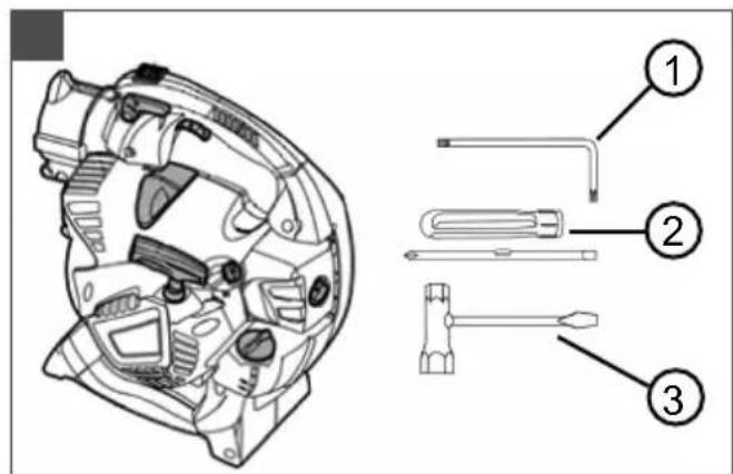
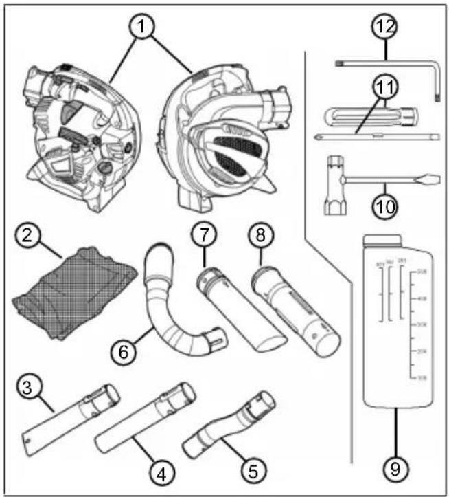
2.3 Scope of supply
The appliance is supplied with all accessory parts in a box. The items listed here are part of the scope of supply. Check that all items are included:
No. Component
| 1 Vacuum/blowing appliance |
| 2 Collecting sack with carrying belt |
| 3 Lower blower tube, with flat nozzle |
| 4 Lower blower tube, with round jet nozzle |
| 5 Upper blower tube, curved |
| 6 Exhaust air manifold |
| 7 Lower vacuum tube |
| 8 Upper vacuum tube |
| 9 Fuel mixture bottle |
| 10 Spark plug spanner with screwdriver |
| 11 Screwdriver handle with plug insert for slotted and cross-head screws |
| 12 Torx ® angled screwdriver |
2.4 Symbols on the machine
| Symbol Meaning | |
 | On/Off toggle switch. This switch is always set to On "I". If the switch is toggled to "0", the appliance immediately switches off. |
 | Symbol on the throttle locking lever. In the lower position, the motor speed can be set as required with the throttle lever. In the upper, engaged position, the motor runs at maximum speed. |
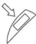 | Arrow on the intake grille. Push the screwdriver into the upper lateral opening of the intake grille in order to open it. |
 | Symbol on the fuel tank cap. Fill in the mixture at a ratio of 40:1, i.e. 40 parts of petrol: 1 part of 2-stroke oil |
 | Fill level indicator on the fuel tank |
 | Symbols for the carburettor setting:■ L = decreases the amount of fuel in the petrol/oil mixture when the motor is warm■ H = increases the amount of fuel in the petrol/oil mixture when the motor is cold |
 | Symbol on the type plate: Weight of the appliance without accessory parts |
 | Symbol on the type plate: Guaranteed sound power in [dB(A)] |
2.5 Product overview
This section describes the parts and controls of the vacuum/blowing appliance. Accessory parts, see chapter 2.3 "Scope of supply", page 27.
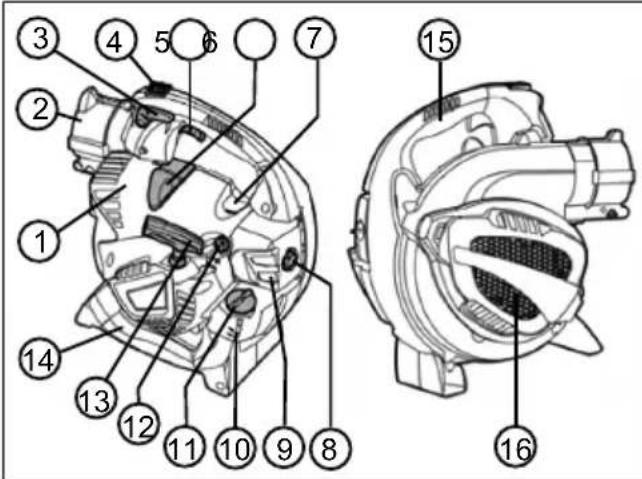
No. Component
| 1 Engine cover |
| 2 Appliance connections for upper blower tube and exhaust air manifold |
| 3 Throttle locking lever |
| 4 On/Off switch |
| 5 Throttle lever |
| 6 Spark plug connector |
| 7 Primer knob |
| 8 Air filter screw |
| 9 Air filter housing |
| 10 Fuel tank |
| 11 Cap of the fuel tank |
| 12 Rotary choke knob |
| 13 Starter handle |
| 14 Lower handle |
| 15 Upper handle |
| 16 Suction grille. Under the vacuum grille: Shredding blade and rotor |
3 SAFETY INSTRUCTIONS
CAUTION! Danger of hearing impairment.
The appliance is extremely loud during operation. This can cause hearing impairment to the operator and to persons and animals in the vicinity.
■ Only work when wearing hearing protection.
- Maintain a safe distance to persons or animals, or switch off the appliance if persons or animals approach.
NOTE It is essential to familiarise yourself with the operation of the appliance. In particular, learn how the appliance can be immediately stopped.
3.1 Operator
■ Young people under 16 years of age and people who do not know the instructions for use are not allowed to use the appliance. Heed any country-specific safety regulations concerning the minimum age of the user.
If you are working with such an appliance for the first time: Have the salesperson or another expert explain the operation of the appliance. Or attend a course.
To operate the appliance, you must be rested and in good physical and mental health. If you must not exert yourself for health reasons, ask your doctor whether it is possible to work with this appliance.
■ Do not operate the machine if you are under the influence of alcohol, drugs or medication.
3.2 Personal protective equipment
■ Wear clothing and protective equipment in accordance with the regulations in order to avoid injuries to the head and limbs, as well as to avoid hearing impairment.
The clothing must be appropriate (tightly fitting) and must not restrict movements. If you have long hair, it is essential to wear a hair net. Never wear loose items of clothing or accessories that be pulled into the appliance, e.g. scarves, loose-fitting shirts, long neck chains.
■ The personal protective equipment comprises:
■ Hearing protection (e.g. ear defenders, especially when working for than 2.5 hours a day)
- Protective glasses
■ Sturdy work gloves, vibration and shock absorbent
■ Safety boots with high-grip sole and steel toe caps
3.3 Handling of petrol and oil
DANGER! Risk of explosion and fire. An escaping petrol/air mixture can cause an explosive atmosphere. Deflagation, explosion and fire can lead to serious and even fatal injuries if fuel is not handled properly.
■ Do not smoke when dealing with petrol.
■ Only handle petrol out of doors and never in enclosed spaces.
It is essential to heed the code of conduct stated below.
■ Only transport and store petrol and oil in containers approved for that purpose. Ensure that children have no access to stored petrol and oil.
In order to avoid ground contamination (environmental protection) when filling, ensure that no petrol or oil enters the soil. Use a funnel for filling.
■ Never fill the appliance in enclosed spaces. Petrol vapours may gather at ground level, and thereby result in a deflagration or even an explosion.
Immediately wipe any spilled petrol off the appliance and the ground. Allow textiles used to wipe off petrol to dry in a well ventilated place before disposing of them. Otherwise, sudden self-ignition may occur.
If petrol has been spilled, petrol vapours occur. For this reason, do not start the appliance at the same location but at least 3 m away.
- Avoid skin contact with mineral oil products. Do not inhale petrol vapours. When filling, always wear protective gloves. Change and clean protective clothing regularly.
■ Ensure that your clothing does not come into contact with petrol. If petrol has got onto your clothing, change it immediately.
■ Never fill the appliance while the motor is running or hot.
3.4 Safety in the workplace
■ Only operate the appliance out of doors and never in enclosed spaces.
■ Only work during daylight or under very bright artificial light.
Before work, remove any hazardous products and objects from the working area, e.g. explosive and inflammable products, hot ashes, combustion residues, smouldering cigarettes, branches, pieces of glass, sharp objects, pieces of metal, stones.
■ Make sure you are standing safely. Avoid wet, slippery ground.
■ When working, move cautiously and slowly. Do not run. Watch out for obstacles.
3.5 Safety of persons, animals and property
■ Only use the appliance for the purposes for which it is intended. Any non-intended use can lead to injuries and property damage.
■ Only switch on the appliance when there are no persons and/or animals in the working area.
- Maintain a safe distance to persons or animals, or switch off the appliance if persons or animals approach.
■ Never hold the exhaust gas jet of the motor against persons and animals or against inflammable products and objects.
- Do not reach into the vacuum and vent grilles when the motor is running. Injuries can occur due to rotating appliance parts.
■ Always switch off the appliance when the vacuum or blowing operation is not needed, e.g. when changing the work area, during maintenance and care work and when pouring in the petrol/oil mixture.
- Immediately switch off the appliance if there is an accident in order to avoid further injuries and/or property damage.
The noise and vibrations of the appliance can increase due to improper use and maintenance. This leads to damage of the health. In this case, immediately switch off the appliance and have it repaired by an authorised service workshop.
■ Never operate the appliance with worn or defective parts. Worn or defective appliance parts can cause serious injuries.
■ Only operate the appliance at the motor speed required for the respective work. Avoid using the maximum speed in order to reduce noise and vibrations.
Take long breaks during your working day so you can recover from the noise and the vibrations. Plan your work in such a way that the
use of devices that generate strong vibrations is spread over several days.
■ Extensive use of the appliance exposes the operator to vibrations, which can lead to circulatory issues ("white fingers"). To avoid this risk, wear gloves and keep your hands warm. If any symptoms of "white fingers" occur, immediately consult a physician. These symptoms include: Numbness, loss of feeling, tingling, itching, pain, reduced muscular strength, changes in the colour or condition of the skin. Normally these conditions affect the fingers, hands or pulse. The risk increases at low temperatures.
- Keep the appliance out of the reach of children.
3.6 Appliance safety
■ Only use the appliance under the following conditions:
The appliance is not dirty, especially not with petrol and oil.
The appliance show no signs of damage, especially the protective grille.
■ All controls function properly.
All accessory parts intended for the respective operating mode are fitted on the appliance.
- Do not overload the machine. It is intended for light work in the private sphere. Overload can lead to damage to the appliance.
- Do not vacuum up any branches, pieces of glass, sharp objects, pieces of metal, stones or other objects. They will damage the shredding blade and the rotor.
■ Never block the vacuum and ventilation grille during operation in order to avoid any overheating of the motor.
- Immediately switch off the appliance if the motor begins to vibrate abnormally or strongly. There is an appliance fault in this case.
■ Never operate the appliance with worn or defective parts. Always replace defective parts with original spare parts from the manufacturer. If the appliance is operated with worn or defective parts, guarantee claims against the manufacturer are excluded.
4 ASSEMBLY AND DISMANTLING
To assemble or dismantle the vacuum/blowing appliance, set it down on a level and stable surface.
The accessory parts are bulky. Make sure there is sufficient space for handling the accessory parts.
4.1 Assembly for blowing operation
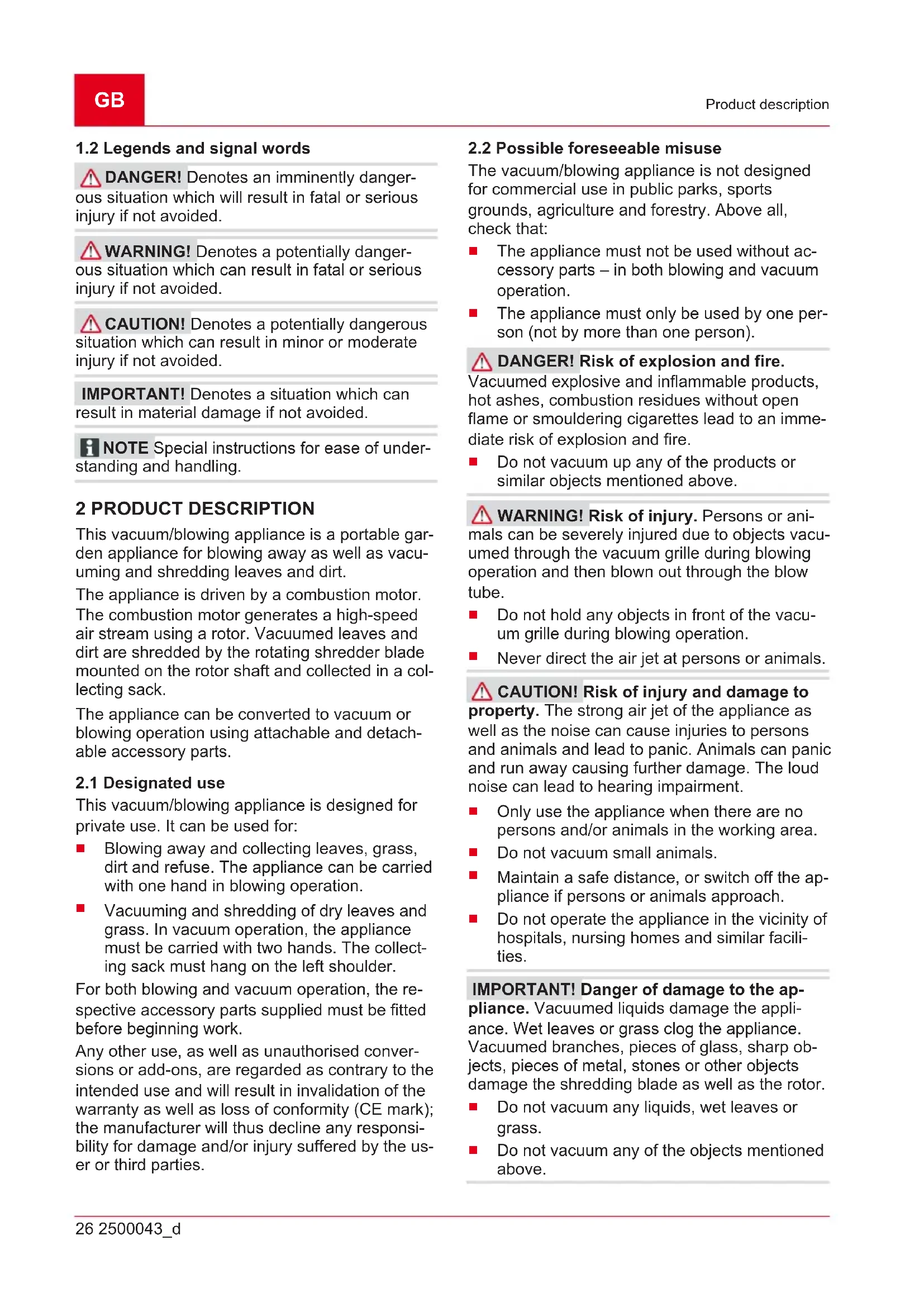
Connecting the upper blower tube to the appliance connection piece (01)
- Align the upper [curved] blower tube (01/1) to the appliance connection piece (01/2) so that the spring (01/3) and groove (01/4) face each other. The two nubs (01/5) of the upper blower tube must point downwards.
- Slide the upper blower tube (01/1) into the appliance connection piece (01/2) until the locking catch (01/6) is clearly heard to engage in the appliance connection piece.
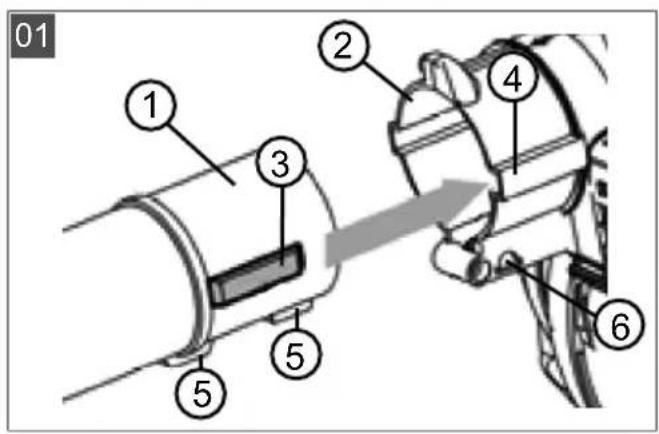
Connecting the lower blower tube to the upper blower tube (02)
There are two types of lower blower tube:
■ With flat nozzle: Generates a flat air jet for heavy, wet leaves and dirt
■ With round jet nozzle: Generates a round air jet for light, dry leaves and dirt
The lower blower tube has a longitudinal groove (02/3) with transverse grooves (02/6), (02/7) connected to it. The cam (02/4) is screwed into the front transverse groove (02/6). The rear transverse groove (02/7) is not used.
-
Align the lower blower tube (02/1) to the upper blower tube (02/2) so that the longitudinal groove (02/3) and the cam (02/4) face each other.
-
Slide the lower blower tube (02/1) over the upper blower tube (02/2) up to the end stop ring (02/5), but not beyond. In this position, the cam (02/4) is located exactly on the front transverse groove (02/6).
-
Turn the lower blower tube clockwise by 90^ until it engages.
NOTE The length of the complete tube cannot be changed. The lower blower tube (02/1) cannot be pushed further over the upper blower tube than the end stop ring (02/5), i.e. the rear transverse groove (02/7) is not used.
4.2 Dismantling the blower tube
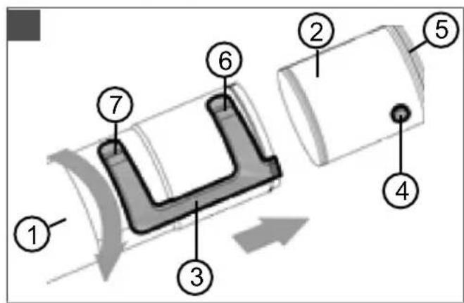
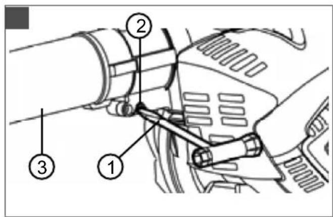
Detaching the lower blower tube from the upper blower tube (03)
- Turn the lower blower tube (03/1) anti-clockwise by 90°. In this position, the cam (03/2) of
the upper blower tube (03/3) is located in the longitudinal groove (03/4).
- Pull the lower blower tube (03/1) off the upper blower tube (03/3).
Removing the upper blower tube from the appliance connection piece (04)
- Slide the screwdriver (04/1) of the spark plug spanner into the hole (04/2) of the locking catch in the appliance connection piece until the widest part of the screwdriver is under the locking catch.
- Turn the screwdriver by 90°; there must be noticeable resistance. The locking catch releases the upper blower tube (04/3). The screwdriver remains inserted.
- Pull out the upper blower tube (04/3).
4.3 Assembly for vacuum operation
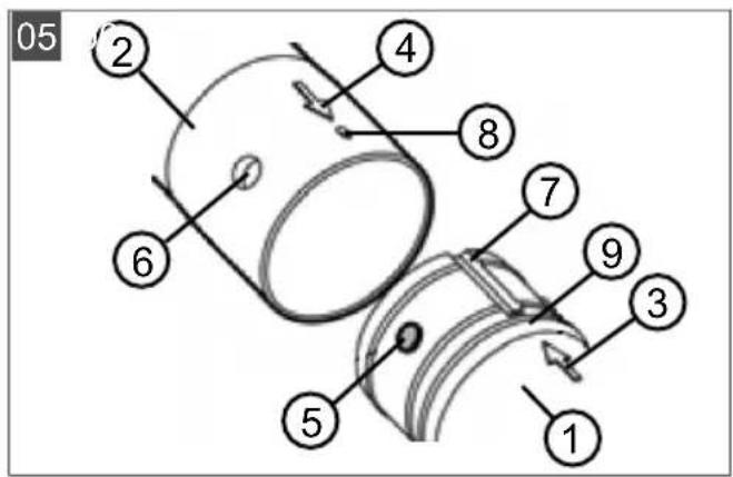
Connecting the lower vacuum tube to the upper vacuum tube (05)
- Align the lower vacuum tube (05/1) to the upper vacuum tube (05/2) so that the two arrows (05/3) and (05/4) face each other. The following components face each other in this position:
■ The cam (05/5) and the engaging holes (05/6)
■ The groove (05/7) on the lower vacuum tube and the cam (05/8) on the upper vacuum tube
- Slide both vacuum tubes firmly together until the following occurs:
■ The cam (05/5) engages in the engaging holes (05/6).
■ The upper vacuum tube impacts the limiting ring (05/9) of the lower vacuum tube.
The two vacuum tubes are now firmly connected together. They are not intended to be detached from each other again.
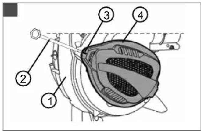
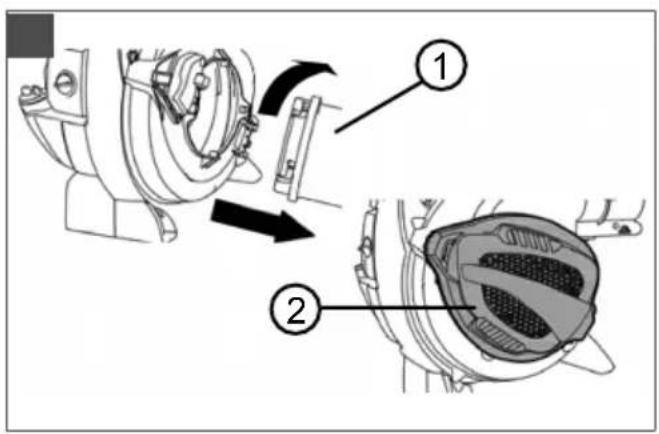
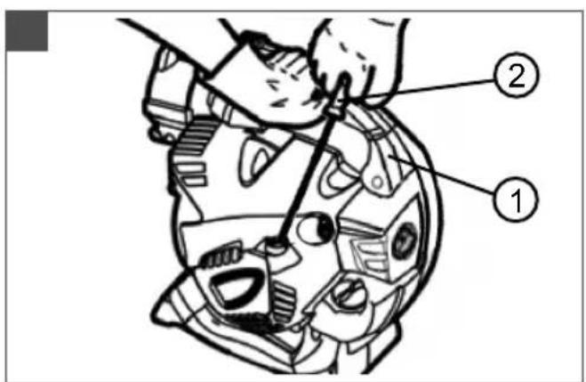
Opening the intake grille of the appliance (06)
- Hold the appliance (06/1) tight.
- Firmly slide the screwdriver (06/2) of the spark plug spanner into the upper lateral opening (06/3) of the intake grille (06/4).
NOTE Do not slide the screwdriver into the front lateral opening to which the arrow (that is mounted on the vacuum grille) points.
- Push the inserted screwdriver, together with the intake grille, away from the appliance. The intake grille swivels up.
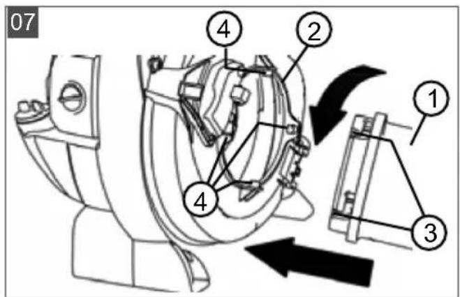
Connecting the upper vacuum tube to the appliance (07)
-
Hold the swivelled-up intake grille tight.
-
Align the upper vacuum tube (07/1) to the housing opening (07/2) as follows:
The openings (07/3) of the transverse grooves and the nubs of the housing opening (07/4) face each other.
The vacuum tube is rotated so that the two arrows (05/3) and (05/4) are at the top.
- Slide the upper vacuum tube (07/1) into the housing opening (07/2) and rotate it firmly anti-clockwise until it engages.
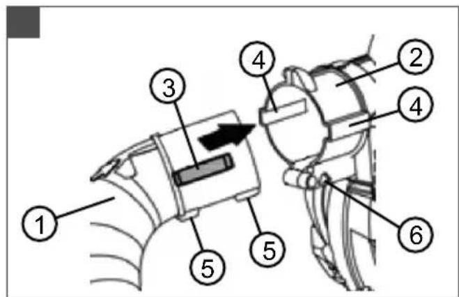
Connecting the exhaust air manifold to the appliance connection piece (08)
-
Align the exhaust air manifold (08/1) to the appliance connection piece (08/2) so that the spring (08/3) and groove (08/4) face each other. The two nubs (08/5) of the exhaust air manifold must point downwards.
-
Slide the exhaust air manifold (08/1) into the appliance connection piece (08/2) until it sticks. The locking catch (08/6) does not engage in the appliance connection piece.
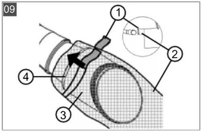
Connecting the collecting sack to the exhaust air manifold (09)
- Open the hook and loop fastener (09/1) on the blow-in opening (09/2) of the collecting sack.
- Slide the blow-in opening (09/2) of the collecting sack over the blow-out connection piece (09/3) of the exhaust air manifold until the hook and loop fastener (09/1) is located behind the bulge (09/4). The zip fastener and carrying belt of the collecting sack must point upwards.
- Pull the hook and loop fastener (09/1) tight and close it.
- Pull on the collecting sack to check that it is now firmly connected to the blow-out connection piece (09/3) of the exhaust air manifold.
- Close the zip fastener of the collecting sack if it is open.
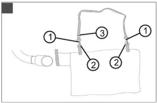
Attaching the carrying belt to the collecting sack (10)
- Click the snap hooks (10/1) of the carrying belt in the rings (10/2) on the collecting sack.
- Pick up the appliance and hang the collecting sack over your left shoulder. Adjust the
length of the carrying belt by moving the buckle (10/3) so the collecting sack is comfortable to carry.
4.4 Dismantling the collecting sack and the vacuum tubes
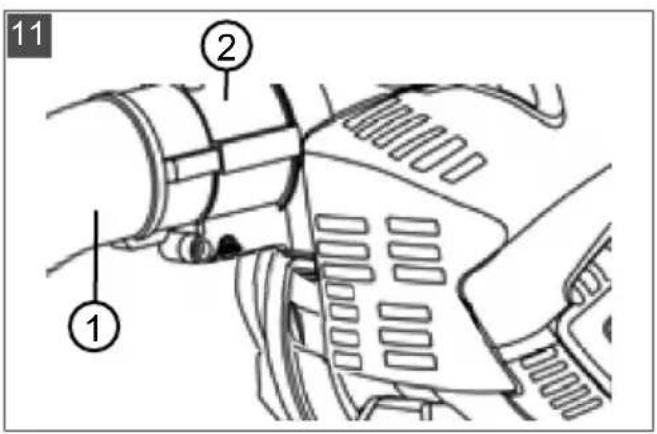
Removing the exhaust air manifold from the appliance connection piece (11)
- Pull the exhaust air manifold (11/1) out of the appliance connection piece (11/2).
It is not necessary to separate the exhaust air manifold from the collecting sack.
Removing the vacuum tube from the housing opening (12)
-
Turn the vacuum tube (12/1) firmly clockwise until it disengages and can be taken off. The intake grille (12/2) folds shut.
-
Push the intake grille (12/2) against the appliance until it engages.
5 START-UP
5.1 Checking the appliance
Check before starting work:
Are all protective grilles undamaged? Have any damaged protective grilles repaired.
■ Are all screws tight? Tighten any loose screws.
Are the upper and lower handles firmly attached to the appliance? Tighten any loose handles.
Are the shredding blade and the rotor under the vacuum grille undamaged? Have any damaged appliance parts repaired.
Is the throttle lever easy to move and does it snap quickly back to the starting position after being released? If not, clean it. Have it repaired if it is defective.
- Can the On/Off switch be easily moved from the "I" to the "0" position and does it snap back again automatically? If not, have it repaired.
Is the spark plug connector firmly connected to the spark plug? Push it tight if it is loose.
Is the air filter clean? Clean it if it is dirty.
Is the petrol tank full? Mix the petrol/oil to produce the mixture and pour it in.
Are all accessory parts for the respective operating mode fitted and undamaged? Fit the remaining accessory parts. Replace any defective accessory parts.
■ For vacuum operation:
Is the collecting sack firmly connected to the exhaust air manifold? If not, slide the blow-in opening of the collecting sack further onto the exhaust air manifold and tighten the hook and loop fastener.
Is the collecting sack closed? Close the zip fastener of the collecting sack.
5.2 Making and pouring in the petrol/oil mixture
IMPORTANT! Danger of motor damage. Pure petrol leads to damage and complete failure of the motor. Guarantee claims against the manufacturer are excluded in this case.
■ Only operate the motor using the specified petrol/oil mixture ratio.
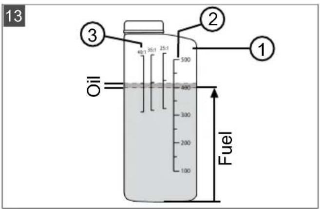
Mixing the petrol/oil to produce the mixture (13)
The 2-stroke motor requires:
-
Lead-free, fresh petrol with an octane rating of at least 90. Petrol stored for longer than 2 months would lead to deposits and malfunctions of the motor.
■ High-quality synthetic oil for 2-stroke motors Mix these two components to produce a petrol/oil mixture of 40:1. -
Hold the fuel mixture bottle (13/1) horizontally and pour in the required amount of petrol:
-
Read the filled amount on the right petrol scale (13/2) "100 – 500" [in ml].
■ Pour in the petrol up to the 300, 400 or 500 ml mark (e.g. 400 ml, see graphic). -
Hold the fuel mixture bottle (13/1) horizontally and pour in the required amount of 2-stroke oil up to the next mark on the left oil scale 40:1 (13/3).
-
Close the fuel mixture bottle (13/1) and shake vigorously several times to thoroughly mix the petrol and oil.
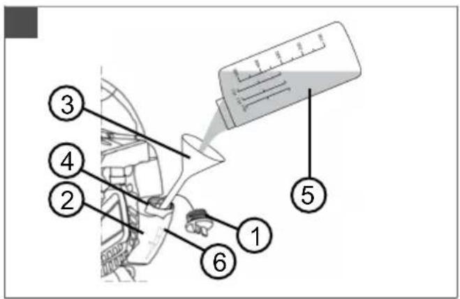
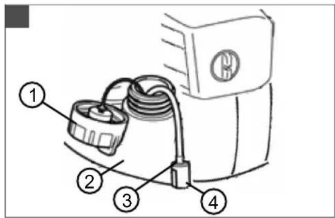
Pouring in the petrol/oil mixture (14)
- Switch off the motor of the appliance.
- Place the appliance on a flat, stable surface. The cap of the fuel tank must point upwards.
- Wipe clean the cap of the fuel tank, the fuel tank and the surrounding appliance parts so that no dirt can get into the fuel tank when the petrol/oil mixture is poured in.
- Open the cap (14/1) of the fuel tank slowly so the pressurised petrol/air mixture in the fuel
tank (14/2) can slowly escape into the atmosphere. Let the cap (14/1) hang on the fuel tank.
- Insert a funnel (14/3) in the filler neck (14/4) of the fuel tank.
- Fill the prepared petrol/oil mixture from the fuel mixture bottle (14/5) up to the upper end of the fill level indicator (14/6) or up to the lower edge of the filler neck (14/4) in the fuel tank, but not beyond it.
- Remove the funnel (14/3) from the opening of the fuel tank (14/2) and tighten the cap (14/1).
- Wipe any spilled petrol/oil mixture off the appliance and the surface.
DANGER! Danger of poisoning from motor exhaust gases. Serious poisoning can be caused by inhaling the motor exhaust gases. Such poisoning can be fatal.
■ Only operate the appliance out of doors and never in enclosed spaces.
■ Do not inhale the motor exhaust gases.
6.1 Starting the engine
Set the appliance on the ground before starting the motor. The blow or vacuum tubes fitted to the appliance must have sufficient space to move.
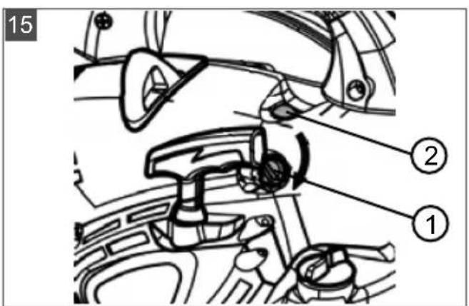
Cold start (15, 16, 17)
If the motor is cold, i.e. if it has not been in use for more than 5 minutes, a "cold start" is carried out.
- Turn the rotary choke knob (15/1) clockwise to the end stop.
- Push the primer knob (15/2) approx. 7 to 10 times fully downward to pump the petrol/oil mixture into the carburettor.
- At the same time:
■ Push the appliance firmly downwards to the ground with one hand on the upper handle (16/1).
■ With the other hand, pull the starter handle (16/2) first carefully and slowly until resistance is felt and then intently and quickly vertically upwards until resistance is felt again (approx. 1 arm length).
■ Let the starter rope roll back up but without letting go of the starter handle (16/2).
-
Repeat this step several times until the motor starts but stops again.
-
Turn the rotary choke knob (15/1) back, i.e. anti-clockwise, to the end stop.
- At the same time:
■ Firmly push the appliance downwards to the ground with one hand on the upper handle (16/1) and fully depress the throttle lever (17/1).
■ With the other hand, pull the starter handle (16/2) first carefully and slowly until resistance is felt and then intently and quickly vertically upwards until resistance is felt again (approx. 1 arm length).
■ Let the starter rope roll back up but without letting go of the starter handle (16/2).
-
Repeat this step several times until the motor starts and then runs properly.
-
Allow the motor to warm up:
-
Hold the throttle lever (17/1) fully depressed for a while so the motor runs warm.
■ Slowly release the throttle lever (17/1). Push it again if the motor no longer runs properly.
■ Release the throttle lever (17/1) when motor has warmed up. It then runs at idle speed.
Warm start (15, 16, 17)
If the motor is still warm from use, i.e. shortly after it was switched off, a "warm start" is carried out. The choke is not used here.
- Check that the rotary choke knob is in the starting position. If not, turn it anti-clockwise to the end stop.
- Push the primer knob (15/2) approx. 2 to 3 times fully downward to pump the petrol/oil mixture into the carburettor.
- At the same time:
■ Push the appliance firmly downwards to the ground with one hand on the upper handle (16/1).
■ With the other hand, pull the starter handle (16/2) first carefully and slowly until resistance is felt and then intently and quickly vertically upwards until resistance is felt again (approx. 1 arm length).
■ Let the starter rope roll back up but without letting go of the starter handle (16/2).
- Repeat this step several times until the motor starts but stops again.
5. At the same time:
■ Firmly push the appliance downwards to the ground with one hand on the upper handle (16/1) and fully depress the throttle lever (17/1).
■ With the other hand, pull the starter handle (16/2) first carefully and slowly until resistance is felt and then intently and quickly vertically upwards until resistance is felt again (approx. 1 arm length).
- Let the starter rope roll back up but without letting go of the starter handle (16/2).
- Repeat this step several times until the motor starts and then runs properly.
NOTE If the choke was accidentally switched on: Turn the rotary choke knob anti-clockwise to the starting position and repeat the warm start several times until the motor starts.
6.2 Changing the motor speed
Use a lower motor speed for light, dry material and dirt or high motor speeds for heavy, wet material and dirt.
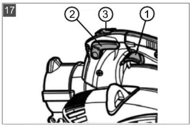
Continuously regulating the speed (17)
- Push the throttle lever (17/1) until the required speed is reached. The motor runs at maximum speed at the throttle lever end stop.
- When changing location in blow or vacuum operation: release the throttle lever (17/1). The motor then runs at idle speed.
Permanently setting the maximum speed (17)
- Pull the throttle locking lever (17/2) upwards until it engages together with the throttle lever (17/1).
- To switch off the maximum speed: Push the throttle locking lever (17/2) downwards. The motor then runs at idle speed.
6.3 Stopping the motor (17)
- Set the motor to idling speed:
■ Push the throttle locking lever (17/2) downwards or
■ release the throttle lever (17/1).
-
Push the On/Off switch (17/3) to "0" and keep it pressed until the motor stops.
-
Release the On/Off switch (17/3). It then springs back to position "I".
7 OPERATING MODES
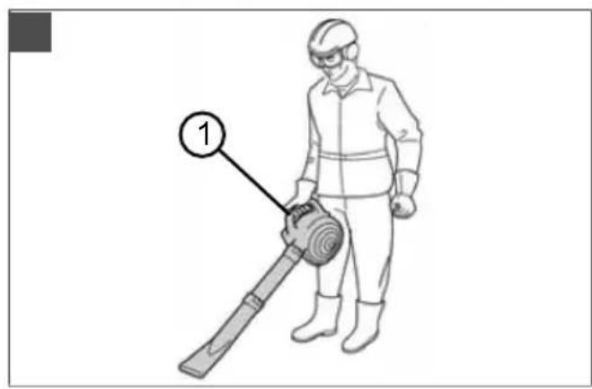
7.1 Working in blowing operation (18)
The appliance can be carried with one hand in blowing operation.
WARNING! Danger of serious injuries from rotating appliance parts. If the vacuum grille is open and the safety switch is blocked, the shredding blade and the rotor can cause serious injuries.
■ Never operate the appliance with the vacuum grille open and the safety switch blocked.
CAUTION! Risk of injury and damage to property. Persons or animals can be injured and soiled by the air jet and blown away material.
It is essential to make sure that the air jet and blown away material does not negatively affect persons or animals or damage objects.
Note the wind direction.
NOTE Never work against the wind to ensure that you and persons behind you are not soiled.
- Fit the blow tubes (see chapter 4.1 "Assembly for blowing operation", page 30).
- Start the motor (see chapter 6.1 "Starting the engine", page 33).
- Raise the appliance with one hand on the upper handle (18/1).
- During work, adjust the motor speed to the material to be blown away (see chapter 6.2 "Changing the motor speed", page 34):
■ Low motor speed: For light, dry material, e.g. leaves, cut grass, chippings, grains and dirt
■ Medium motor speed: For material of medium size and weight, e.g. wet leaves
■ High motor speed: For very heavy or wet material, e.g. fresh snow and coarse dirt
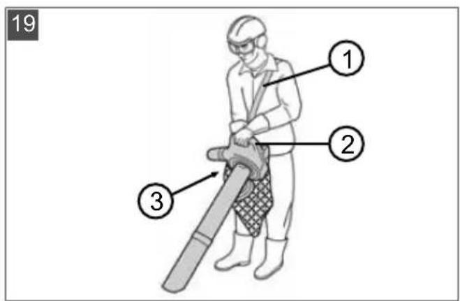
7.2 Working in vacuum operation (19)
In vacuum operation, the appliance must be carried with both hands. Hang the collecting sack over your left shoulder by the carrying belt.
IMPORTANT! Danger of damage to the appliance. Vacuumed liquids damage the appliance. Wet leaves or grass clog the appliance. Vacuumed branches, pieces of glass, sharp objects, pieces of metal, stones or other objects damage the shredding blade as well as the rotor.
■ Do not vacuum any liquids, wet leaves or grass.
■ Do not vacuum any of the objects mentioned above.
NOTE Do not vacuum small animals.
- Fit the vacuum tubes and the collecting sack (see chapter 4.3 "Assembly for vacuum operation", page 31).
- Starting the motor:
■ Pull the exhaust air manifold of the collecting sack out of the appliance connection piece so the appliance can be set on the ground to start the motor.
■ Start the motor (see chapter 6.1 "Starting the engine", page 33).
- Hang the collecting sack over your left shoulder by the carrying belt (19/1). The collecting sack must hang free of your shoulder and must not be twisted so that it can fill unhindered.
- Lift the appliance with the right hand on the upper handle (19/2).
- With the left hand, slide the exhaust air manifold of the collecting sack into the appliance connection piece until it sticks.
- Hold the appliance with both hands: on the upper handle (19/2) and on the lower handle (19/3).
- While working:
■ Operate the appliance at medium/high motor speed.
■ Hold the inlet opening of the vacuum tube just a few centimetres above the ground.
- Do not fill the collecting sack completely. The vacuum power decreases if the collecting sack is full.
■ After vacuuming a dangerous object: Immediately stop the motor and remove the object. Check if the shredding blade or the rotor has been damaged.
- Emptying the collecting sack:
■ Stop the motor (see chapter 6.3 "Stopping the motor (17)", page 34).
■ Pull the exhaust air manifold of the collecting sack out of the appliance connection piece and set down the appliance.
■ Open the zip fastener of the collecting sack and shake it out.
8 MAINTENANCE AND CARE
Proper maintenance and care is necessary to ensure the functionality and safety of the appliance. Note the following points:
■ Only carry out maintenance and care work if you have the necessary knowledge and tools.
■ Wait until the motor has fully cooled.
■ Wear protective gloves.
■ Only replace any worn or defective appliance parts with original spare parts from the manufacturer.
Do not carry out any maintenance and care work that is not described in these instructions for use. Instruct an authorise service workshop to do this work. Any infringements will invalidate the manufacturer's warranty.
The intervals for the maintenance and care work mentioned here can be found in the maintenance schedule (see chapter 8.6 "Maintenance schedule", page 37).
8.1 Cleaning/replacing the air filter (20)
- Dismantling the air filter:
■ Undo the air filter screw (20/1) until the air filter housing (20/2) is loose.
■ Pull off the air filter housing (20/2).
■ Pull the filter sponge (20/3) off the peg (20/4).
- Cleaning:
■ Press out the filter sponge (20/3) and wash it with soap and water. Do not use petrol or other solvents.
■ Let the filter sponge (20/3) dry thoroughly so it no longer contains any water. A wet filter can make the motor difficult to start.
■ Thoroughly wipe out the air filter housing (20/2) with a cleaning rag.
- Replacing:
- Replace the filter sponge if it is no longer elastic or falls apart.
- Fitting the air filter:
■ Insert the filter sponge (20/3) on the peg (20/4) and push it to the end stop.
- Insert the air filter housing (20/2) to the end stop and keep it pressed.
■ Screw in the air filter screw (20/1) until the air filter housing (20/2) is held tight.
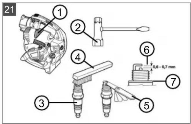
8.2 Maintaining the spark plug (21)
1. Removing the spark plug:
■ Pull off the spark plug connector (21/1).
■ Use the spark plug spanner (21/2) to unscrew the spark plug (21/3).
2. Assessing the condition of the spark plug:
If the spark plug is reddish-brown: The motor is working correctly and the spark plug is in order. If necessary: Carefully brush the spark plug (21/3) clean with a fine wire brush (21/4).
If the spark plug is sooty, oily, encrusted, melted or bridged: The spark plug is defective. Install a new spark plug. Use the specified spark plug type (see chapter 12 "Technical data", page 40).
If, after a short period of operation, the spark plug is defective again, the motor and the carburettor settings must be checked by an authorised service workshop.
3. Check the electrode spacing:
Use a feeler gauge (21/5) to check that the electrode spacing (21/6) is 0.6 – 0.7 mm. If not, carefully knock the electrodes together or carefully bend them apart.
4. If the specified interval is reached or the spark plug is defective:
- Install a new spark plug. Use the specified spark plug type (see chapter 12 "Technical data", page 40).
5. Installing the spark plug:
■ Make sure the spark plug sealing ring (21/7) sits on the spark plug.
■ Screw the spark plug (21/3) back in by hand and tighten it thoroughly using the spark plug spanner (21/2).
- Plug the spark plug connector (21/1) firmly back on.
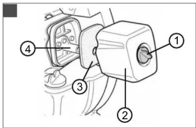
8.3 Checking/replacing the fuel filter (22)
The felt-like fuel filter is located in the fuel tank and is plugged onto the vacuum head. If the fuel filter becomes hard, dirty or clogged, less petrol flows to the motor. In this case, the fuel filter must be replaced.
It is recommended that an authorised service workshop carries out this work.
1. Preparing the appliance:
■ To empty the fuel tank: Let the motor turn until it stops by itself.
Place the appliance on a flat, stable surface. The cap of the fuel tank must point upwards.
■ Wipe clean the cap of the fuel tank, the fuel tank and the surrounding appliance parts so that no dirt can get into the fuel tank.
2. Checking/replacing the fuel filter:
■ Unscrew the cap (22/1) of the fuel tank (22/2). Let the cap (22/1) hang on the fuel tank.
■ Use a wire hook to pull the vacuum head (22/3) out of the fuel tank (22/2).
- Check the fuel filter (22/4). If the felt has become hard, dirty or clogged: Pull off the fuel filter (22/4) and slide a new fuel filter onto the vacuum head.
3. Slide the vacuum head (22/3) back into the fuel tank (22/2).
4. Mixing and pouring in the petrol/oil mixture:
■ see chapter 5.2 "Making and pouring in the petrol/oil mixture", page 32
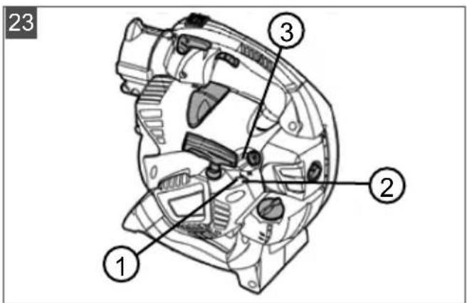
8.4 Carburettor settings (23)
The following carburettor regulating screws are visible on the appliance:
L = idle mixture regulating screw (23/1): Reduces the amount of fuel in the petrol/oil mixture when the motor is warm
■ H = full load mixture regulating screw (23/2): Increases the amount of fuel in the petrol/oil mixture when the motor is cold
■ Idle regulating screw on the rotary choke knob (23/3)
This regulating screw can only be adjusted with a special socket wrench not included in the scope of delivery.
NOTE The carburettor must only be adjusted by an authorised service workshop.
8.5 Checking/tightening the appliance screws (24)
The screws of the appliance can loosen due to the vibrations of the motor. Tools are available in
the scope of delivery for checking/tightening the screws of the appliance:
■ Torx® angled screwdriver (24/1)
■ Screwdriver handle with plug insert for slotted and cross-head screws (24/2)
- Spark plug spanner with screwdriver (24/3)
- Insert the matching tool in the screw.
- Turn the screw clockwise with a short jerk.
NOTE Do not turn the regulating screws on the carburettor. Therefore no socket wrench has been supplied for these regulating screws.
8.6 Maintenance schedule
The following information relates to normal application conditions. Under special conditions, such as working for a particularly long time or in a very dirty working area, the specified maintenance intervals must be shortened accordingly.
Parts are only allowed to be renewed by genuine spare parts.
1) This process must be carried out by your dealer or an authorised service workshop.
| Interval Components Work to be performed | ||
| Before starting work | Complete appliance Visual inspection for condition | |
| Controls Functional check | ||
| Carburettor Check idle setting | ||
| Anti-vibration components Check | ||
| After daily work | Complete appliance Clean | |
| After every refilling | Complete appliance Visual inspection for condition | |
| Controls Functional check | ||
| Carburettor Check idle setting | ||
| Every 100 operating hours | Spark plug Renew | |
| Every 12 months | Air filters Clean | |
| Fuel filter in the tank Renew | ||
| If not functioning properly | Air filters Clean | |
| Fuel filter in the tank Check | ||
| Spark plug Adjust the electrode spacing | ||
| All accessible screws (ex-cept setscrews) | Check | |
| Anti-vibration components Check | ||
| Throttle lever Clean or replace | 1) | |
| On/Off switch Clean or replace | 1) | |
| Silencer Clean | 1) | |
| If defective | Air filters Renew | |
| Fuel filter in the tank Renew | ||
| Anti-vibration components Replace 1) | ||
| Silencer Replace 1) | ||
| Starter cable Replace 1) | ||
| collection bag Renew | ||
| Safety sticker Renew | ||
| If necessary | Air filters Clean or replace | |
| Fuel filter in the tank Renew | ||
| Carburettor Adjust idle setting 1) | ||
| Cooling air inlet Clean | ||
| All accessible screws (except setscrews) | Retighten | |
| Anti-vibration components Check | ||
| Canister for petrol and 2-stroke oil | Clean | |
9 HELP IN CASE OF MALFUNCTION
| Malfunction Cause Remedy | ||
| Motor does not start, or only starts with difficulty. | Motor start was not carried out properly. | see chapter 6.1 "Starting the engine", page 33 |
| Spark plug is dirty, defective or the electrode spacing is not right. | see chapter 8.2 "Maintaining the spark plug (21)", page 36 | |
| Air filter is dirty. see chapter 8.1 "Cleaning/replacing the air filter (20)", page 35 | ||
| Carburettor settings are not correct. | Contact an authorised service workshop. | |
| Inlet grille is open and the vacuum tube is not inserted. | Close the inlet grille or fit the vacuum tube (see chapter 4.3 "Assembly for vacuum operation", page 31). | |
| Blower tube is not inserted. Fit the | blower tube (see chapter 4.1 "Assembly for blowing operation", page 30). | |
| Motor starts, but the motor output is low. | Air filter is dirty or filter sponge is worn. | see chapter 8.1 "Cleaning/replacing the air filter (20)", page 35 |
| Carburettor settings are not correct. | Contact an authorised service workshop. | |
| Motor not running smoothly and motor speed not increasing when the throttle is applied. | Spark plug is dirty, defective or the electrode spacing is not right. | see chapter 8.2 "Maintaining the spark plug (21)", page 36 |
| Carburettor settings are not correct. | Contact an authorised service workshop. | |
| Collecting sack is full or dirty. Empty the collecting sack (see chapter 7.2 "Working in vacuum operation (19)", page 34). Shake out the collecting sack. Remove any adhering, vacuumed material with a hand brush. | ||
| Motor exhaust smoking heavily, appears blue. | Amount of oil in the petrol/oil mixture is too high. | Pour in petrol/oil mixture with correct mixture ratio. see chapter 12 "Technical data", page 40 see chapter 5.2 "Making and pouring in the petrol/oil mixture", page 32 |
| Carburettor settings are not correct. | Contact an authorised service workshop. | |
| Motor starts abnormally and vibrates heavily. | Appliance/motor parts have become detached and/or are damaged. | 1. Stop the motor. 2. Inspect the appliance for damage. 3. Check the spark plug (see chapter 8.2 "Maintaining the spark plug (21)", page 36). 4. Contact an authorised service workshop. |
10 TRANSPORT
Transporting the appliance between two working areas
■ Switch off the motor.
■ Hold the appliance by the handles.
- Avoid obstructing anyone with the vacuum or blow tubes.
■ Never bump anything with the vacuum or blow tubes.
Transporting the appliance in a vehicle
■ Switch off the motor.
■ Remove the vacuum and blow tubes as well as the exhaust air manifold and the collecting sack from the appliance.
- Put the appliance into the vehicle and fix in place. This avoids it tipping over when driving and the petrol/oil mixture running out.
Place all accessory parts (where possible from the size) in the collecting sack and close it. This avoids uncontrolled movement in the vehicle when driving.
11 STORAGE
If you are not going to use the appliance for longer than 2 – 3 months, the following work is necessary to avoid any damage:
1. Empty the fuel tank:
- Let the motor turn until it stops by itself. Then there is no longer any petrol/oil mixture in the fuel tank and in the carburettor and deposits cannot form.
2. Cleaning the appliance:
■ Wipe the entire appliance and accessory parts with a cleaning rag. Do not use petrol or other solvents.
■ Shake out the collecting sack. Remove any adhering, vacuumed material with a hand brush.
■ Remove any dirt from all appliance openings (including intake grille and cooling openings for the motor).
■ Open the intake grille and clean the shredding blade and the rotor. Lightly oil the shredding blade using a cleaning rag.
3. Oiling the cylinder:
■ Let the appliance cool down completely.
■ Pull off the spark plug connector and unscrew the spark plug.
- Drop a little oil into the spark plug opening.
■ Slowly pull on the starter handle so the piston moves and the oil is distributed in the cylinder.
■ Screw the spark plug back in tightly and plug in the spark plug connector.
4. Store the appliance in a dry place where possible.
12 TECHNICAL DATA
| 442Item no.: 127380 | |
| Dimensions (L x W x H) [mm], without tubes 350 x 250 x 350 | |
| Weight [kg] | |
| ■ With accessories for blowing operation | 4.7 |
| ■ With accessories for vacuum operation | 5.8 |
| Displacement [cm3] 27.6 | |
| Maximum motor power [kW] 0.8 | |
| Maximum motor speed [rpm] 8300 | |
| Spark plug CHAMPION RCJ7Y | |
| Volume of the fuel tank [l] 0.4 | |
| Petrol Lead-free, minimum 90 octane | |
| Oil Synthetic, for 2-stroke motors | |
| Fuel mixture ratio [petrol:2-stroke oil] 40:1 | |
| Measured sound pressure level LpA [dB(A)] | 93.9 |
| Measurement uncertainty | 3 |
| Measured sound power LW A [dB(A)] 106.6 | |
| Guaranteed sound power [dB(A)] 109 | |
| Air throughput [m3/h] | |
| ■ In blowing operation | 610 |
| ■ In vacuum operation | 600 |
| Maximum air speed [m/s] 72 | |
| Measured vibration level [m/s2] | |
| ■ Upper handle | 2.0 |
| ■ Lower handle | 1.4 |
| Measurement uncertainty | 1.5 |
13 AFTER-SALES / SERVICE
In the event of questions of warranty, repair or spare parts, please contact your nearest AL-KO Service Centre. These can be found on the Internet at: www.al-ko.com/service-contacts
14 PROTECTION OF THE ENVIRONMENT
Protection of the environment is a relevant and fundamental aspect when using this appliance and is of equal benefit to good neighbourliness as well as our habitat.
The avoidance of noise is active part of protecting the environment. Noise causes damage to health. Disturb your neighbour as little as possible. Only operate the appliance during the locally permitted operating times and only for as long as absolutely necessary.
■ Strictly follow the safety instructions concerning the handling of petrol and oil (see chapter 3.3 "Handling of petrol and oil", page 29). Avoid contaminating the ground.
■ Dispose of used oil in accordance with the applicable environmental regulations.
- Hand in used oil to the nearest oil collecting point in a sealed container. Every point of sale is obliged to accept used oil.
Do not dispose of used oil with normal household waste. Do not pour it down the sink, onto the ground or into the sewers.
■ Follow the local regulations for the disposal of leaves and grass. They must be disposed of separately from normal household waste at the specified local collection points.
■ Follow the local regulations for the disposal of leaves and grass. They must be disposed of separately from normal household waste at the specified local collection points.
- Do not dispose of replaced appliance parts or the decommissioned appliance in the environment, but at the specified local collection points.
15 GUARANTEE
We will resolve any material or manufacturing faults on the appliance during the legal warranty period for claims relating to faults, in accordance with our choice either to repair or replace. The legal warranty period is determined by the legislation of the country in which the appliance was purchased.
Our warranty promise applies only if:
■ These operating instructions are heeded
■ The appliance is handled correctly
■ Original spare parts have been used
The warranty becomes void in the case of:
■ Unauthorised repair attempts
■ Unauthorised technical modifications
Non-intended use
The guarantee excludes:
■ Paint damage that can be attributed to normal wear and tear
■ Wear parts that are marked with a frame xxxxxx (x) on the spare parts card
The guarantee period commences with purchase by the first end user. The date on the proof of purchase is decisive. In the event of a guarantee claim, please take this guarantee declaration and the original proof of purchase, and contact your dealer or the nearest authorised customer service centre. This statement does not affect the purchaser's statutory claims for defects against the vendor.
TRADUCTION DE LA NOTICE D'UTILISATION ORIGINALE
Table des matières
N° Pièce
N° Pièce
www.al-ko.com/service-contacts
14 PROTECTION DE L'ENVIRONNEMENT
N.° Componente
N.° Componente
N. Componente
www.al-ko.com/service-contacts
14 TUTELA DELL'AMBIENTE
Št. Sestavni del
Št. Sestavni del
Hladni zagon (15, 16, 17)
Topli zagon (15, 16, 17)
www.al-ko.com/service-contacts
14 VAROVANJE OKOLJA
Br. Dio
| 1 Pokrov motora |
| 2 Nastavci na uređaju za gornju cijev za puhanje i ispušni razvodnik |
| 3 Poluga za određivanje gasa |
| 4 Sklopka za uključivanje/isključivanje |
| 5 Poluga gasa |
| 6 Utikač svjećice |
| 7 Gumb primera |
| 8 Vijak filtra zraka |
| 9 Kućište filtra zraka |
| 10 Spremnik goriva |
| 11 Zatvarač spremnika goriva |
| 12 Okretni gumb prigušnika |
| 13 Ručka pokretača |
| 14 Donja ručka |
| 15 Gornja ručka |
| 16 Usisna rešetka. Ispod usisne rešetke: nož za usitnjavanje i rotor |
3 SIGURNOSNE NAPOMENE
OPREZ! Opasnost od oštećenja sluha.
www.al-ko.com/service-contacts
14 ZAŠTITA OKOLIŠA
Zaštita okoliša je relevantan i prioritetan aspekt pri uporabi ovog uređaja i u jednakoj mjeri doprinosi ugodnom susjedstvu i našem životnom prostoru.
Бр. Саставни део
Бр. Саставни део
www.al-ko.com/service-contacts
14 ЗАШТИТА ЖИВОТНЕ СРЕДИНЕ
Nr Element
Č. Součást
Č. Součást
1 Kryt motoru
www.al-ko.com/service-contacts
14 OCHRANA ŽIVOTNÍHO PROSTŘEDÍ
Nr. Komponent
Nr. Komponent
Koldstart (15, 16, 17)
Varmstart (15, 16, 17)
www.al-ko.com/service-contacts
14 MILJ∅BESKYTTELSE
Nr Komponent
Nr Komponent
Kallstart (15, 16, 17)
Varmstart (15, 16, 17)
Nr. Komponent
Nr. Komponent
| 1 Motorkledning |
| 2 Apparatstuss for øvre blåserør og lufterør |
| 3 Gasslåsespak |
| 4 Av / på-bryter |
| 5 Gasshendel |
| 6 Tennplugghette |
| 7 Pumpeknapp |
| 8 Luftfilterskrue |
| 9 Luftfilterhus |
| 10 Drivstofftank |
| 11 Lokk til drivstofftanken |
| 12 Chokedreieknapp |
| 13 Starthåndtak |
| 14 Nedre håndtak |
| 15 ∅vre håndtak |
| 16 Sugegitter. Under sugegitteret: hakkekniv og rotor |
3 SIKKERHETSANVISNINGER
Kaldstart (15, 16, 17)
Varmstart (15, 16, 17)
8 VEDLIKEHOLD OG PLEIE
Nro Osa
Nro Osa
Номер компонента
1 Крышка двигателя
www.al-ko.com/service-contacts
Imported by: AL-KO Gardentech UK Ltd, Murray way, Wincanton, Somerset, BA9 9RS / UK | +44 (0) 1963
828055
shop.uk@al-ko.com | www.alko-garden.uk
AL-KO Service: www.al-ko.com/service-contacts


- Inhaltsverzeichnis
- Nr. Bauteil
- Kaltstart (15, 16, 17)
- Warmstart (15, 16, 17)
- ABOUT THESE OPERATING INSTRUCTIONS
- Symbols on the title page
- Symbol Meaning
- Legends and signal words
- PRODUCT DESCRIPTION
- Designated use
- Possible foreseeable misuse
- DANGER! Risk of explosion and fire.
- Scope of supply
- Symbols on the machine
- Product overview
- SAFETY INSTRUCTIONS
- CAUTION! Danger of hearing impairment.
- Operator
- Personal protective equipment
- Handling of petrol and oil
- Safety in the workplace
- Safety of persons, animals and property
- Appliance safety
- ASSEMBLY AND DISMANTLING
- Assembly for blowing operation
- Connecting the upper blower tube to the appliance connection piece (01)
- Connecting the lower blower tube to the upper blower tube (02)
- Dismantling the blower tube
- Detaching the lower blower tube from the upper blower tube (03)
- Removing the upper blower tube from the appliance connection piece (04)
- Assembly for vacuum operation
- Connecting the lower vacuum tube to the upper vacuum tube (05)
- Opening the intake grille of the appliance (06)
- Connecting the upper vacuum tube to the appliance (07)
- Connecting the exhaust air manifold to the appliance connection piece (08)
- Connecting the collecting sack to the exhaust air manifold (09)
- Attaching the carrying belt to the collecting sack (10)
- Dismantling the collecting sack and the vacuum tubes
- Removing the exhaust air manifold from the appliance connection piece (11)
- Removing the vacuum tube from the housing opening (12)
- START-UP
- Checking the appliance
- Making and pouring in the petrol/oil mixture
- Mixing the petrol/oil to produce the mixture (13)
- Pouring in the petrol/oil mixture (14)
- Starting the engine
- Cold start (15, 16, 17)
- Warm start (15, 16, 17)
- At the same time:
- Changing the motor speed
- Continuously regulating the speed (17)
- Permanently setting the maximum speed (17)
- Stopping the motor (17)
- OPERATING MODES
- Working in blowing operation (18)
- Working in vacuum operation (19)
- NOTE Do not vacuum small animals.
- MAINTENANCE AND CARE
- Cleaning/replacing the air filter (20)
- Maintaining the spark plug (21)
- Removing the spark plug:
- Assessing the condition of the spark plug:
- Check the electrode spacing:
- If the specified interval is reached or the spark plug is defective:
- Installing the spark plug:
- Checking/replacing the fuel filter (22)
- Preparing the appliance:
- Checking/replacing the fuel filter:
- Slide the vacuum head (22/3) back into the fuel tank (22/2).
- Mixing and pouring in the petrol/oil mixture:
- Carburettor settings (23)
- Checking/tightening the appliance screws (24)
- Maintenance schedule
- TRANSPORT
- Transporting the appliance between two working areas
- Transporting the appliance in a vehicle
- STORAGE
- Empty the fuel tank:
- Cleaning the appliance:
- Oiling the cylinder:
- Store the appliance in a dry place where possible.
- AFTER-SALES / SERVICE
- PROTECTION OF THE ENVIRONMENT
- GUARANTEE
- TRADUCTION DE LA NOTICE D'UTILISATION ORIGINALE
- Table des matières
- PROTECTION DE L'ENVIRONNEMENT
- TUTELA DELL'AMBIENTE
- Hladni zagon (15, 16, 17)
- Topli zagon (15, 16, 17)
- VAROVANJE OKOLJA
- SIGURNOSNE NAPOMENE
- OPREZ! Opasnost od oštećenja sluha.
- ZAŠTITA OKOLIŠA
- ЗАШТИТА ЖИВОТНЕ СРЕДИНЕ
- Č. Součást
- OCHRANA ŽIVOTNÍHO PROSTŘEDÍ
- Koldstart (15, 16, 17)
- Varmstart (15, 16, 17)
- MILJ∅BESKYTTELSE
- Kallstart (15, 16, 17)
- SIKKERHETSANVISNINGER
- Kaldstart (15, 16, 17)
- VEDLIKEHOLD OG PLEIE
- Nro Osa
- Номер компонента
Brand : AL-KO
Model : Solo 442
Category : Vacuum Cleaner