
HDS 9144 St - Heating Kärcher - Free user manual and instructions
Find the device manual for free HDS 9144 St Kärcher in PDF.



| Product type | Stationary high-pressure cleaner with heating |
| Brand | Kärcher |
| Model | HDS 9/14 St (1.698-917) |
| Operating pressure | 14 MPa (140 bars) |
| Water flow rate | 500-930 l/h (adjustable) |
| Max. hot water temperature | 98 °C |
| Max. steam temperature | 155 °C |
| Power consumption | 6.4 kW |
| Voltage / Frequency | 400 V / 50 Hz (three-phase) |
| Protection type | IPX5 |
| Fuel | Fuel EL or diesel |
| Fuel consumption | 5.8 kg/h |
| Gross heating capacity | 68 kW |
| Typical operating weight | 164.4 kg |
| Dimensions (L × W × H) | 1124 × 558 × 687 mm |
| Sound pressure level | 74 dB(A) |
| Vibrations (gun handle) | 2.2 m/s² |
| Safety devices | Dry-run protection, pressure switch, safety valve, flame monitoring, overload protection, residual gas thermostat |
| Maintenance | Oil change every 1000 h, strainer cleaning, descaling if necessary |
| Included accessories | EASY! Force gun, EASY! Lock lance, nozzle, HP hose 10 m |
| Warranty | According to national conditions (see manual) |
Frequently Asked Questions - HDS 9144 St Kärcher
User questions about HDS 9144 St Kärcher
0 question about this device. Answer the ones you know or ask your own.
Ask a new question about this device
Download the instructions for your Heating in PDF format for free! Find your manual HDS 9144 St - Kärcher and take your electronic device back in hand. On this page are published all the documents necessary for the use of your device. HDS 9144 St by Kärcher.
USER MANUAL HDS 9144 St Kärcher
Chairman of the Board of Management
S. Reiser Director Regulatory Affairs & Certification
71364 Winnenden (Germany)
Tel.: +49 7195 14-0
Fax: +49 7195 14-2212
Winnenden, 2018/10/01
Warranty
Please read and comply with these original instructions prior to the initial operation of your appliance and store them for later use or subsequent owners.
Before first start-up it is definitely necessary to read the safety indications Nr. 5.956-309.0!
Before first start-up it is definitely necessary to read the safety indications Nr. 5.956-309.0!
- In case of transport damage, inform the vendor immediately.
Environmental protection
| Environmental protection | EN 1 |
| Danger or hazard levels. | EN 1 |
| Symbols on the machine | EN 1 |
| General notes on safety. | EN 1 |
| Proper use | EN 2 |
| Function | EN 2 |
| Safety Devices. | EN 2 |
| Device elements | EN 3 |
| Start up | EN 4 |
| Operation | EN 4 |
| Shutting down | EN 6 |
| Shutdown | EN 6 |
| Storage | EN 6 |
| Transport | EN 6 |
| Technical specifications. | EN 7 |
| Care and maintenance | EN 9 |
| Troubleshooting | EN 1 |
| Accessories | EN 1 |
| Installing the plant | EN 14 |
| EU Declaration of Conformity | EN 1 |
| Warranty | EN 1 |
| Customer Service | EN 1 |
| Recurring tests. | EN 1 |
Please do not release engine oil, fuel oil, diesel and petrol into the environment. Protect the ground and dispose of used oil in an environmentally-clean manner.
| The packaging material can be recycled. Please do not throw the packaging material into household waste; please send it for recycling. | |
| Old appliances contain valuable materials that can be recycled; these should be sent for recycling. Batteries, oil, and similar substances must not enter the environment. Please dispose of your old appliances using appropriate collection systems. |
Please do not release engine oil, fuel oil, diesel, or petrol into the environment. Protect the ground and dispose of used oil in an environmentally-clean manner.
Kärcher detergents are easy to dispose of. This means that the functioning of an oil separator is not hampered. Please find a list of recommended detergents in the chapter "Accessories".
Notes about the ingredients (REACH)
You will find current information about the ingredients at: www.kaercher.com/REACH
Danger or hazard levels
DANGER
Pointer to immediate danger, which leads to severe injuries or death.
WARNING
Pointer to a possibly dangerous situation, which can lead to severe injuries or death.
CAUTION
Pointer to a possibly dangerous situation, which can lead to minor injuries.
ATTENTION
Pointer to a possibly dangerous situation, which can lead to property damage.
Symbols on the machine

High-pressure jets can be dangerous if improperly used. The jet may not be directed at persons, animals, or technical equipment or at the appliance itself.
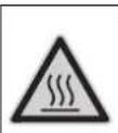
Risk of burns on account of hot surfaces!
General notes on safety
- Please follow the national rules and regulations for fluid spray jets of the respective country.
- Please follow the national rules and regulations for accident prevention of the respective country. Fluid spray jets must be tested regularly and the results of these tests must be documented in writing.
- The heating appliance of the machine is an ignition plant. All national laws and regulations about heating systems must also be followed. If the plant is operated in rooms, then there should be adequate measures for safely diverting the exhaust gases out of the room (smoke gas pipes without draught interceptors). Further, there must also be adequate supply of fresh air.
- As per the applicable national guidelines, the first time this high-pressure cleaner must be taken into operation by a skilled person. KÄRCHER has already performed this initial start-up for you and has documented it accordingly. The documentation can be requested at your KÄRCHER partner. Please have the part and plant number of the appliance available when enquiring about the documentation.
- We would like to point out that the appliance must be repeatedly checked by a skilled person as prescribed by the applicable national regulations. Please contact your KÄRCHER partner.
- Please follow the safety instructions which are attached to the used detergents (normally on the packing label).
- The appliance/accessories must not be modified.
Statutory Requirements, Guidelines and Rules
Before installing the machine, it is necessary to get the approval of the local chief chimney cleaner.
The statutory requirements of civil engineering laws, trade laws and emission control norms must be followed at the time of installation. We wish to bring to your notice the following statutory regulations, guidelines and standards:
- The device may only be installed by a specialized company according to the national regulations.
- All national laws and regulations about installation of electrical appliances must also be followed.
- Only Customer Service engineers trained by Kärcher may perform settings and carry out maintenance tasks and repairs.
- The local guidelines must be followed while installing the chimney.
Work-stations
The work station is located at the operating field. Depending on the plant installation, other work-stations are located at the accessories (spraying units) that are connected to the feeder points.
Personal safety gear

Wear ear plugs to protect your ears against hearing loss while cleaning parts that produce high sound levels.
- Wear protective clothing and safety goggles to protect against splash back containing water or dirt.
Proper use
The machine is used for removing dirt from surfaces using a freeflowing water jet. It is mainly used for cleaning machines, vehicles and facades.
DANGER
Risk of injury! Follow the respective safety regulations upon employment at gas stations or other dangerous areas.
Please do not let mineral oil contaminated waste water reach soil, water or the sewage system. Perform engine cleaning and bottom cleaning therefore only on specified places with an oil trap.
Quality requirements for water:
ATTENTION
Only clean water may be used as high pressure medium. Impurities will lead to increased wear and tear or formation of deposits in the appliance and accessories.
If recycled water is used, the following limit values must not be exceeded.
| pH value 6,5...9,5 | |
| electrical conductivity * Conductivity | fresh water +1200 μS/cm |
| settleable solids ** < 0,5 mg/l | |
| total suspended solids *** < 50 mg/l | |
| Hydrocarbons < 20 mg/l | |
| Chloride < 300 mg/l | |
| Sulphate < 240 mg/l | |
| Calcium < 200 mg/l | |
| Total hardness < 28 °dH | < 50 °TH < 500 ppm (mg CaCO3/l) |
| Iron < 0,5 mg/l | |
| Manganese < 0,05 mg/l | |
| Copper | < 2 mg/l |
| Active chloride | < 0,3 mg/l |
| free of bad odours | |
| * Maximum total 2000 μS/cm** Test volume 1 l, settling time 30 min*** no abrasive substances | |
Function
- Cold water reaches the suction side of the high pressure pump via the engine cooling coil and the swimmer tank. The water softening agent is added in the swimmer tank. The pump transports the water and the sucked detergent through the continuous heater. The proportion of detergent in the water can be adjusted using the dosing valve. The continuous heater is heated by a heater.
- The high pressure outlet is connected to a high pressure network existing in the building. The hand-spray gun is connected to the feeder points of this network using a high pressure hose.
Safety Devices
Safety devices serve for the protection of the user and must not be put out of operation or bypassed with respect to their function.
Safety mechanism against lack of water in swimmer tank
The safety mechanism against lack of water prevents the high pressure pump from being switched on when there is no water.
Safety mechanism against lack of water in safety block
The safety mechanism against lack of water prevents the heater from over-heating when there is no water. The burner operates only when there is adequate water supply.
Pressure switch
The pressure switch switches off the machine when the working pressure is exceeded. Do not change the setting.
Safety valve
The safety valve opens when there is a problem in the pressure switch. This valve is set and sealed in the factory. Do not change the setting.
Flame monitoring
In case of fuel shortage or problems with the burner, the flame monitor switches off the burner. The indicator lamp Burner failure (E) glows.
Over-current protection
If the burner engine is blocked, the switch for protection against over-current gets released. The engine of the high pressure pump is protected through an engine protection switch and a winding protection switch.
Exhaust thermostat
The exhaust thermostat is triggered when the exhaust temperature exceeds 300°C . The appliance is switched off.
Pressure release in the high pressure system
When the machine is switched off using the hand-spray gun, a solenoid valve installed in the high pressure system opens when the operations stand-by time has elapsed; this causes the pressure to fall.
Safety catch
The safety catch on the trigger gun prevents the appliance from being switched on unintentionally.
Device elements
Figure 1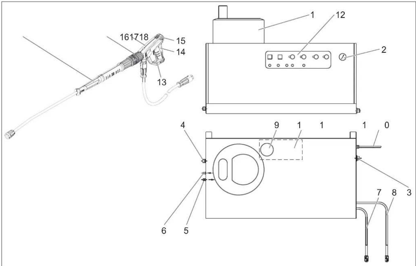
1 Burner 2 Manometer 3 Fresh water inlet with sieve 4 High-pressure outlet EASY!Lock 5 Fuel pipe feeder 6 Fuel pipe backflow 7 Detergent suck hose I 8 Detergent suck hose II (optional) 9 Softener container
10 Power supply 11 Float tank 12 Operating field 13 Safety lever 14 Trigger 15 Safety latch of the hand spray gun 16 Trigger gun EASY!Force 17 Pressure/quantity regulation at the hand spray gun 18 Spray lance EASY!Lock
Operating field
Figure 2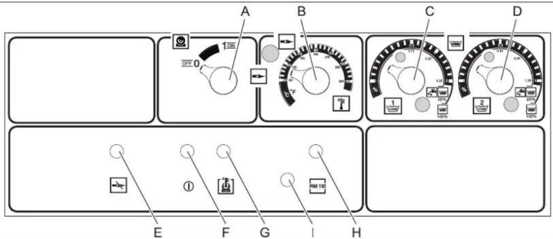
A Power switch B Temperature controller C Dosage valve I for detergent D Dosage valve II for detergent (optional) E Indicator lamp burner failure F "Ready for use" indicator lamp
G Indicator lamp for engine over-heating H Indicator lamp for protection against calcification I Stopper - Releaser for burner engine
Start up
riangle WARNING
Risk of injury! Appliance, accessories, supply lines and connections must be in fault-free condition. If they are not in a perfect state then the appliance must not be used.
Power connection
- For connection values, see technical data and type plate.
- The electrical connections must be done by an electrician according to IEC 60364-1.
Operation
△DANGER
Danger of explosion! Do not spray flammable liquids.
DANGER
Risk of injury! Never use the appliance without the spray lance attached. Check and ensure proper fitting of the spray lance prior to each use. The screw connection of the spray lance must be finger-tight.
△DANGER
Risk of injury! Hold the hand spray gun and the spray pipe firmly with both hands.
△DANGER
Risk of injury! The trigger and safety lever may not be locked during the operation.
△DANGER
Risk of injury! Contact Customer Service if the safety lever is damaged.
Safety instructions
The operator must use the appliance correctly. When working with the appliance, he must consider the local conditions and pay due care and attention to other persons, in particular children, who are nearby.
Never leave the appliance unattended when it is in operation.
DANGER
- Danger of scalding by hot water! Do not direct the water jet on persons or animals.
- Risk of burns on account of hot surfaces! Do not touch uninsulated pipes and hoses when hot water operations are on. Hold the jet pipe only at the handles. Do not touch the exhaust holder of the continuous heater.
- Risk of poisoning or itching on account of detergent! Follow the given instructions for using detergents. Store detergents safely and protect them against access by unauthorised persons.
DANGER
Risk to life on account of electric shock! Do not direct the water jet on the following equipment:
- Electrical appliances and plants, the unit itself,
- all electricity-carrying parts in the working area.
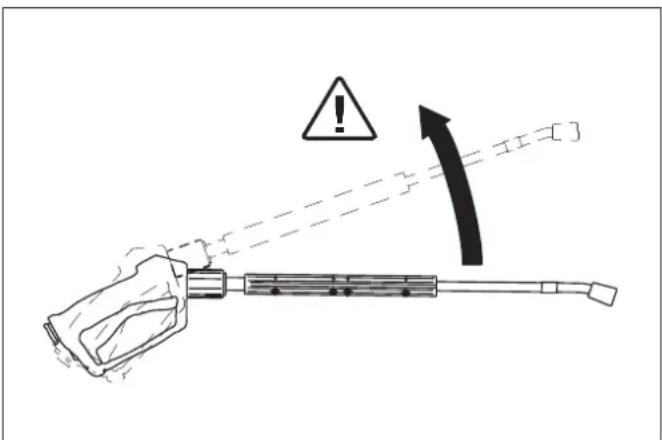
There is a recoil pressure arising from the water jet that comes out from the spray pipe. The angular spray pipe brings about an upward force.
DANGER
- Risk of injury! The recoil pressure of the spray lance can throw you off balance. You may fall. The spray lance can fly off and cause damage to persons. Search for a secure place to stand and hold the gun firmly.
- The jet must not be directed at other persons or directed by the user at him/herself to clean clothing or footwear.
- Risk of injury from parts flying off! Flying-off fragments or objects can injure people or animals. Never direct the water jet on fragile or loose objects.
- Risk of accident on account of damage! Clean tyres and valves from a minimum distance of 30 cm.
WARNING
Danger from substances that are harmful to health! Do not spray the following materials as they can swirl up substances that are harmful to health:
Materials containing asbestos, Materials that could contain substances harmful to health.
DANGER
- Risk of injury on account of the emanating water jet that could be hot! Only original Kaercher high pressure hoses are optimally suited for the plant. No guarantee can be given if you use any other hoses.
- Detergents can prove to be a health hazard! If any detergents are added, the water let out of the plant is not of potable quality.
- Risk of hearing impairment while working on noise-making parts! If so, wear ear plugs.
Opening/closing the trigger gun
To open the trigger gun: Actuate the safety lever and trigger. To close the hand spray gun: Release the safety lever and trigger.
Replace the nozzle
DANGER
Risk of injury! Switch the appliance off prior to replacing nozzle and activate hand spray gun until device is pressured less.
Secure the trigger gun. To do so, push the safety catch towards the front. Replacing the nozzle.
Making the plant ready for operations
DANGER
Risk of injury on account of the emanating water jet that could be hot!
DANGER
Check the high pressure hose for damage before every use. Please arrange for the immediate replacement of a damaged high pressure hose.
Check high pressure hose, pipe connections, fittings and water jet for damage every time before use. Check hose coupling to ensure that it sits firmly and is leak-proof.
ATTENTION
Risk of damage on account of dry running.
Check filling level of the detergent container and refill if required. Check softener fluid level and refill if necessary.
Switch-off in case of emergency
Turn the appliance switch (A) to "0". Shut off water supply. Activate trigger gun until device is pressure-less.
Set working pressure and flow rate
Appliance setting
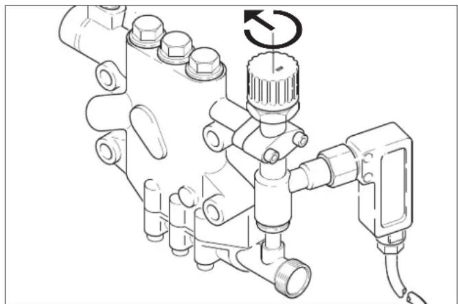
Turning the quantity regulation valve in clock-wise direction will result in higher working pressure and larger volume. Turning the quantity regulation valve in an anti-clockwise direction will result in lower working pressure and smaller quantities.
Adjusting the pressure/quantity regulation of the trigger gun (option)
DANGER
Risk of injury! When adjusting the pressure/quantity regulation, make sure that the screw connection of the spray lance does not become loose.
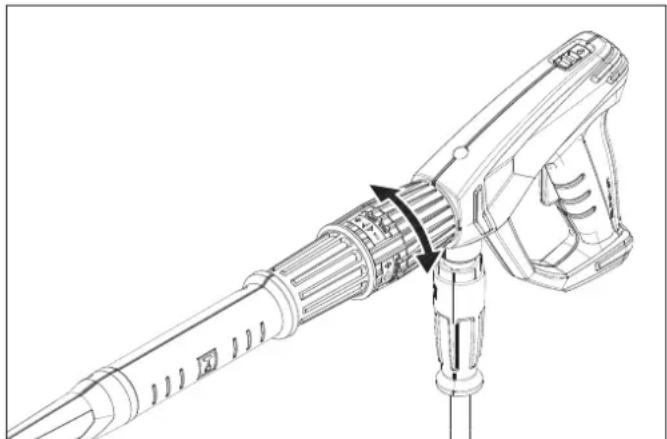
Turning the water quantity regulator to the right gives more water flow and higher working pressure. Turning the water quantity regulator to the left gives lesser water flow and lower working pressure.
Operating with cold water
Open the water supply.

Symbol "Engine on"
Release the trigger gun. To do so, push the safety catch towards the back. Open the trigger gun and set the appliance switch (A) to "1" (motor on). The indicator lamp for operational readiness (F) shows that the appliance is in stand-by mode and ready to be operated.
Operating with hot water
DANGER
Scalding danger!
ATTENTION
Hot water operations without fuel will cause damage to the fuel pump. Ensure adequate fuel supply before starting hot water operations.
If required, the burner can also be turned on subsequently.

Symbol "Burner on"
Turn the appliance switch (A) to "Burner on". Set the desired water temperature on the thermostat (B). Maximum temperature is 98°C.
Operating with steam
DANGER
Scalding danger! The operating pressure must not exceed 3.2 MPa (32 bar) when operating with temperatures above 98°C. For shifting from hot water to steam operations, first cool down the machine and switch it off. Then do the change-over as follows:
Replace the high pressure nozzle with the steam nozzle (accessory).
| Order No. Type | |
| 4.116-000 HDS 9/14 | |
| 4.116-001 HDS 12/14 |
Set the thermostat to 150°C.
Without pressure/quantity regulation at the trigger gun
Set the water flow regulation valve of the high pressure pump to minimum water flow (turn in the anti-clockwise direction).
With pressure/quantity regulation at the trigger gun (option)
Set the water flow regulation valve of the high pressure pump to maximum water flow (turn in the clockwise direction). Set the water flow regulator at the trigger gun to minimum water flow by turning it towards the left.
Operations stand-by
- If the trigger gun is closed during operation, the appliance will switch off. The appliance will automatically start again when you open the gun again within the stand-by period (2 ... 8 minutes).
- If the stand-by period is exceeded, the safety time mechanism switches off the pump and the burner. The indicator lamp Operations Stand-by (F) goes off.
- To restart the appliance, set the appliance switch to "0" and then switch on the appliance again. If the appliance is operated using remote control, the appliance can be restarted by using the corresponding switch of the remote control device.
Selecting the nozzle
- Vehicle tyres are only cleaned using the flat spray nozzle (25°) from a minimum spraying distance of 30 cm . The round spray should never be used to clean tyres.
The following nozzles can be selected for all other tasks:
| Dirt Nozzle | Spray an-gle | Part no.: Pressure [MPa] | Recoil [N] | ||
| HDS 9/14 | |||||
| strong 000 | 60 0° 5.76 | 65-240 14 44 | |||
| medium | 25060 25° | 5.76 | 65-027 | ||
| light | 40060 40° | 5.1 | 30-087 | ||
| HDS 12/14 | |||||
| strong 000 | 80 0° 5.76 | 5-243 14 55 | |||
| medium | 25080 25° | 5.76 | 65-061 | ||
| light | 40080 40° | 5.76 | 65-221 | ||
Use the following nozzles if the pipe length is more than 20m or for more than 2× 10m high pressure hose NW8:
| Dirt Nozzle | Spray ar-gle | Part no.: Pressure [MPa] | Recoil [N] |
| HDS 9/14 | |||
| strong 007 | 5 0° 5.765 | -242 10 37 | |
| medium | 2575 25° | 5.765 | -057 |
| light | 4075 40° | 5.765 | -220 |
Detergent dosing
- Detergents simplify the cleaning task. They are sucked in from an external detergent tank.
- The basic model of the appliance is equipped with a dosing valve (C). A second dosing device (dosing valve D) can also be procured as special accessory. It is then possible to use two different detergents.
- The dosing quantity is set at the detergent dosing valves (C or D) at the operating panel. The set value corresponds to the percentage share of the detergent.
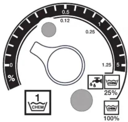
- The outer scale is applicable while using undiluted detergents (100% CHEM).
- The inner scale is applicable while using 1 + 3 pre-diluted detergents (25% CHEM + 75% water).
The following table gives the detergent consumption for the values on the outer scale:
| HDS 9/14 | |||
| Position | 0.5 | 1 | 5 |
| Detergent quantity [l/h] | 14...15 | 2...24 | 50 |
| Detergent concentration [%] | 1.5 | 2.5 | 5 |
| HDS 12/14 | |||
| Position | 0.5 | 1 | 5 |
| Detergent quantity [l/h] | 10...13 | 2...27 | 60 |
| Detergent concentration [%] | 1 | 2 | 5 |
The exact dosing depends on: - Viscosity of the detergent - Suction height - Flow resistance of the high pressure pipe
If an exact dosing is required, then measure the detergent quantity that is sucked in (for e.g. by sucking in from a measurement beaker).
Note: For list of recommended detergents refer the chapter "Accessories".
Refilling the softener
ATTENTION
There can be calcium deposits in the continuous heater if you use the appliance without softeners.
If the softener tank is empty, the indicator lamp for protection against calcification (H) begins to glow.
Figure 1 - Pos. 9
Refill the softener tank with softener liquid RM 110 (2.780-001).
Shutting down
DANGER
Danger of scalding by hot water. After the operation with hot water or steam, the device must be operated with opened gun with cold water for at least two minutes.
After operation with detergent
If operating with hot water, set the thermostat (B) to the lowest temperature. Use the appliance for at least 30 seconds without detergent.
Turn off the appliance
Turn the appliance switch (A) to "0". Shut off water supply. Activate trigger gun until device is pressure-less. Secure the hand spray gun using the safety catch so that it doesn't open accidentally.
Shutdown
If the machine is not to be used for a longer period or if it is not possible to save it in a frost-free environment, then you must take the following measures (see chapter "Maintenance and care"):
Drain water. Flush device with anti-freeze agent. Switch off the main switch and secure it or unplug the Cekon plug.
Storage
CAUTION
Risk of injury and damage! Note the weight of the appliance in case of storage.
Transport
ATTENTION
Protect the trigger from damage during transport.
CAUTION
Risk of injury and damage! Observe the weight of the appliance when you transport it.
When transporting in vehicles, secure the appliance according to the guidelines from slipping and tipping over.
Technical specifications
| HDS 9/14 HDS 12/14 HDS 12/14 | ||||
| 1.698-917 1.699-921 1.699-923 | ||||
| Performance data | ||||
| Operating pressure of water (using standard nozzle) | MPa (bar) | 14 (140) | 14 (140) | 14 (140) |
| Max. operating pressure for working with steam (using steam nozzle) | MPa (bar) 3.2 (32) | 3.2 (32) 3.2 (32) | ||
| Part no. of steam nozzle -- 4.116-000 4.116-001 4.116-001 | ||||
| Max. excess operating pressure (safety valve) | MPa (bar) | 18.5 (185) | 18.5 (185) | 18.5 (185) |
| Water flow (can be regulated in a phase-less manner) l/h (l/min) | min) 500-930 | (8.3-15.5) | 600-1200 (10-20) | 600-1200 (10-20) |
| Steam flow rate l/h (l/min) 470 (7.8) 600 (10) 600 (10) | ||||
| Suction of detergent (can be regulated in a phaseless man-ner) | l/h (l/min) | 0-50 (0-0.8) | 0-60 (0-1) | 0-60 (0-1) |
| Water connection | ||||
| Min. feed volume | l/h (l/min) | 1100 (18.3) | 1300 (21.7) | 1300 (21.7) |
| Feed pressure (min.) | MPa (bar) | 0.1 (1) | 0.1 (1) | 0.1 (1) |
| Max. feed pressure | MPa (bar) | 0.6 (6) | 0.6 (6) | 0.6 (6) |
| Electrical connection | ||||
| Current type | -- 3N~ | 3N~ | 3N~ | |
| Frequency | Hz | 50 | 50 | 50 |
| Voltage | V 400 | 400 | 230 | |
| Connected load | kW | 6.4 | 7.5 | 8.2 |
| Electrical protection (slow) | A 16 20 | 32 | ||
| Type of protection | -- IPX5 | IPX5 | IPX5 | |
| Protective class | -- I | I | I | |
| Maximum allowed net impedance | Ohm | (0.381+j 0.238) | -- | -- |
| Power supply | mm² | 5 x 2.5 | 5 x 2.5 | 5 x 4 |
| Temperature | ||||
| Max. feed temperature | °C 30 | 30 | 30 | |
| Max. operating temperature of hot water | °C | 98 | 98 | 98 |
| Max. operating temperature of steam | °C | 155 | 155 | 155 |
| Temperature increase during maximum water flow | °C | 56±2 | 54±2 | 54±2 |
| Gross heating performance | kW | 68 85 | 85 | |
| Fuel consumption | kg/h | 5.8 | 7.1 | 7.1 |
| Chimney draught | kPa | 0.01-0.04 | 0.01-0.04 | 0.01-0.04 |
| Exhaust flow - full load | kg/h | 124 | 155 | 155 |
| Fuel | ||||
| Fuel | -- Fuel oil EL or | Diesel | Fuel oil EL or Diesel | Fuel oil EL or Diesel |
| Dimensions and weights | ||||
| Length | mm | 1124 | 1124 | 1124 |
| Width | mm | 558 | 558 | 558 |
| Height | mm | 687 | 699 | 699 |
| Typical operating weight | kg | 164.4 | 178.8 | 178.8 |
| Values determined as per EN 60335-2-79 | ||||
| Noise emission | ||||
| Sound pressure level LpA | dB(A) | 74 | 76 | 76 |
| Uncertainty KpA | dB(A) | 1 | 1 | 1 |
| Hand-arm vibration value | ||||
| Hand spray gun | m/s² | 2.2 | 2.3 | 2.3 |
| Spray lance | m/s² | 1.8 | 2.1 | 2.1 |
| Uncertainty K | m/s² | 1.0 | 1.0 | 1.0 |
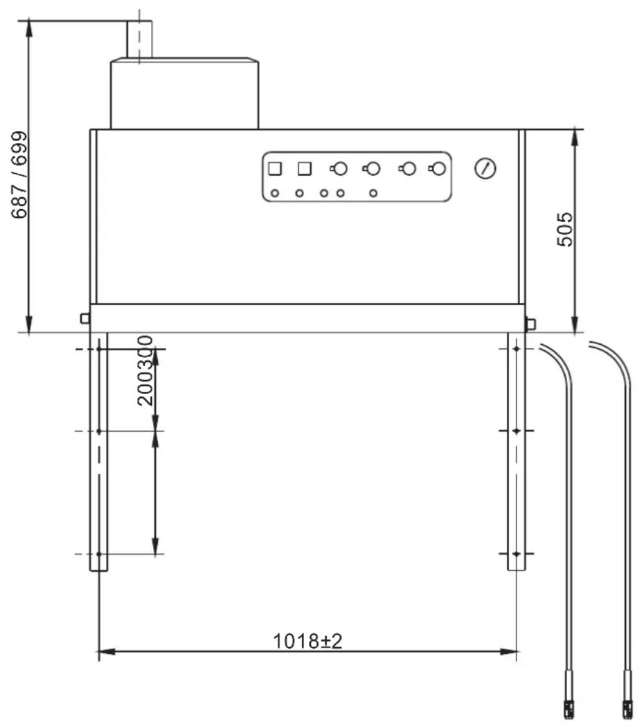
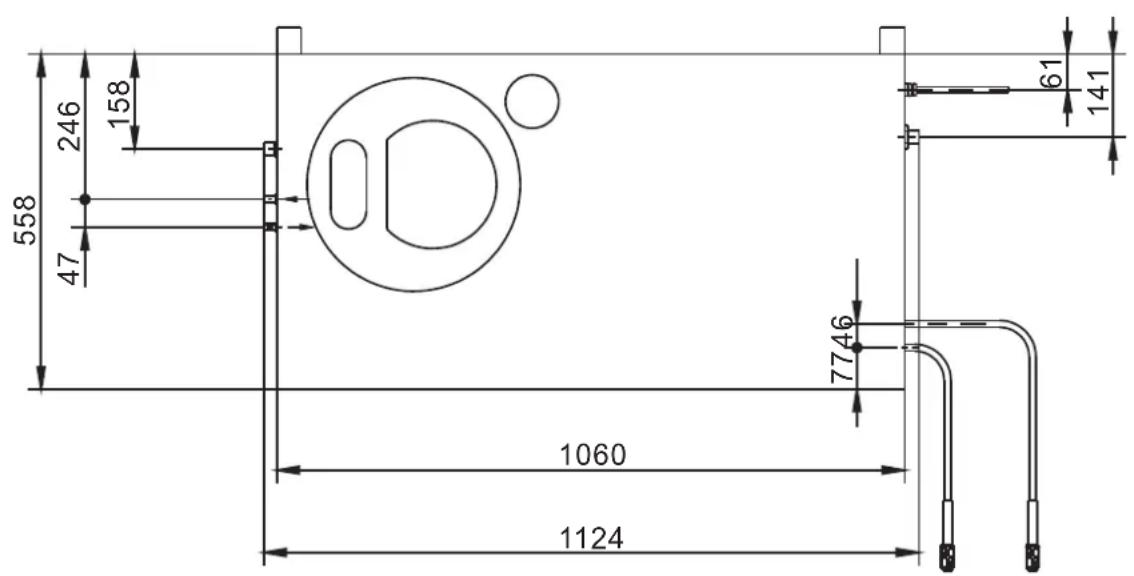
Care and maintenance
DANGER
Risk of injury! The main switch of the vacuum cleaner is to be switched off or the Cekon plug must be unplugged while carrying out any repairs or maintenance jobs.
Maintenance schedule
| Time Activity Assembly affected Performance of whom | ||||
| daily Check hand-spray gun | hand spray gun Check whether | the hand-spray gun closes tightly without any leaks. Check the protection mechanism against accidental switching. Replace defective hand-spray guns. | Operator | |
| check high pressure hoses | Outlets, hoses towards working machine | Check hoses to see if there are damages. Replace defect hoses immediately. Danger of accident! | Operator | |
| Check the connecting line with mains plug | Electrical connection with plug/ socket | Check the connecting line with mains plug for damages. If the power cord is damaged, please arrange immediately for the exchange by an authorized customer service or a skilled electrician. | Operator | |
| weekly or after 40 operating hours | Check oil level | Oil tank at the pump | If the oil is milky, it needs to be replaced. | Operator |
| Check oil level Oil tank at the pump Check oil level | of the pump. Refill oil if required (Order no. 6.288-016) | Operator | ||
| Cleaning the sieve | Sieve in water inlet See section "Clean sieve". Operator | |||
| monthly or after 200 operating hours | Clean and check the ignition electrodes | Ignition electrodes located in the lid of the continuous heater | Unscrew the fuel pipe, dismantle the electrode holder and clean the electrodes. Check the electrode setting according to the diagram on the following page and make the necessary adjustments. | Trained operator |
| Check pump | High-pressure pump | Check the pump for leaks. If the leakage is more than 3 drops per minute, call Customer Service. | Operator | |
| Check for internal deposits | Entire plant | Operate the machine using the spray pipe without the high pressure nozzle. If the operating pressure on the manometer of the machine increases to more than 3 MPa, then the plant needs to be decalcified. The same is applicable when an operating pressure of more than 0.7 - 1 MPa is detected while operating the machine without high pressure pipe (water comes out freely at the high pressure outlet). | Operator trained in de-calcification | |
| Cleaning the sieve | Sieve in the water shortage safeguard | See section "Clean sieve". Operator | ||
| half-yearly or after 1000 operating hours | Oil change | High-pressure pump | Drain off oil. Fill in 1 I new oil (Order no. 6.288-016). Check oil level in the oil tank. | Operator |
| check, clean | Entire plant | Visual inspection of the plant, check high pressure connections to see that they are not leaking check that the over-flow valves are not leaking, check high pressure hoses, pressure tanks, clean/ replace fuel filters, remove the rust/ calcium deposits from the heating coil, clean/ replace ignition electrodes, clean/ replace burner nozzle, adjust burner. | Customer Service | |
| annual | Safety check | Entire plant | Perform a safety inspection as per the applicable national rules and regulations for liquid spray jets of the respective country. | Technical expert |
| at least every 5 years, recurring | Pressure test | Entire plant | Perform the pressure test as per manufacturer's instructions. | Technical expert |
Maintenance contract
You can enter into a maintenance contract with the concerned Kaercher Sales Office for the machine.
Cleaning the sieve
Sieve in water inlet
Figure 1 - Pos. 3
Shut off water supply. Remove the water inlet hose on the appliance. Push out the sieve from the connection using a screwdriver. Clean the sieve. Assemble it back in the reverse sequence.
Sieve in the water shortage safe guard
Remove covering panels. Unscrew the bracket from the safety block.
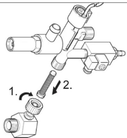
Turn in screw M8x30 into the sieve. Pull out the screw and the sieve using pliers. Clean the sieve. Assemble it back in the reverse sequence.
Electrode setting
The ignition electrodes must be set according to the following specifications:
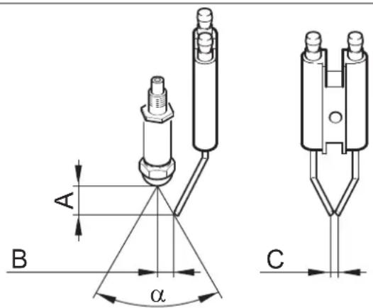
| A | B | C | a | |
| HDS 9/14 4.5±0.5 3.5$±0.5 3+0.560° | ||||
| HDS 12/14 3.5±0.5 3.5±0.5 3+0.5560° | ||||
Descaling
When there are deposits formed in the pipe connections, there is an increase in the flow resistance; this can cause the pressure switch to be triggered.
DANGER
Risk of explosion due to combustible gases! Smoking strictly prohibited during decalcification. Ensure proper ventilation.
DANGER
Risk of chemical burns on account of acid! Wear protective glasses and protective gloves.
Performance
According to statutory requirements, only tested and approved boiler decrusting agents may be used.
- RM 100 (Order No. 6.287-008) dissolves chalk and simple compounds of chalk and detergents residues.
- RM 101 (Order No. 6.287-013) dissolves the deposits that cannot be dissolved using RM 100.
Fill a 20 litre container with 15 litres of water. Add one litre of boiler decrusting agent. Connect the water hose directly to the pump and hang the other free end into the container. Insert the connected spray pipe without nozzle into the container. Open the hand-spray gun and do not close it during the decalcification process. Switch on the appliance switch to "Burner on" until the temperature of approx. 40°C is reached. Switch off the appliance and let it stand for 20 minutes. The hand-spray gun must remain opened. Then pump out the machine until empty.
Note: As an anti-corrosion measure and for neutralising the acid residue, we recommend that you finally pump an alkaline solution through the machine (for e.g. RM 81) via the detergent tank.
Frost protection
The machine should be stored in frost-free rooms. In case there is frosting risk, for e.g. if the machine is installed in open areas, then the machine must first be emptied and flushed using an anti-freezing agent.
Drain water
Screw off water supply hose and high pressure hose. Operate device for max. 1 minute until the pump and conduits are empty. Screw off supply hose at boiler bottom and drain heating spiral empty.
Flush device with anti-freeze agent
Note: Observe handling instructions of the anti-freeze agent manufacturer.
Fill in normal anti-frost agents in the swimmer tank right until the top. Place the collection trough under the high pressure exit. Switch on the appliance and let it run until the safety mechanism against lack of water in swimmer tank gets activated and the machine is switched off.
A certain corrosion protection is achieved with this as well.
Troubleshooting
DANGER
Risk of injury! The main switch of the vacuum cleaner must be switched off or the Cekon plug must be unplugged while carrying out any repairs or maintenance jobs.
| Fault Possible cause Remedy of whom | |||
| Machine is not running; indicator lamp for operations stand-by (F) is not glowing | There is no voltage in the machine. | Check electrical mains. Electrician | |
| Safety time switch is on. | Switch off the appliance switch briefly and switch it on again. | Operator | |
| Fuse in the control circuit (F3) has burnt off. Fuse is located in the control transformer (T2). | Install a new fuse; if it burns out again, then remove the cause for the over-loading. | Customer Service | |
| Pressure switch HP (High pressure) or LP (Low pressure) is defective. | Check pressure switch. Customer Service | ||
| Timer module (A1) defective. | Check connections, replace if required. | Customer Service | |
| Exhaust thermostat (B8) tripped. | Allow plant to cool down. Unlock the exhaust thermostat (B8). Eliminate the cause for the disturbance. | Customer Service | |
| + Indicator lamp for engine over-heating (G) is glowing | Thermal sensor (WS) in the engine or the over-current protection switch (F1) has got activated. | Rectify cause for over-loading. Customer Service | |
| The water shortage safeguard in the swimmer tank has got activated. | Remove the water shortage. | Operator | |
| Burner does not ignite or the flame glows off during operation | Thermostat (B) has been set at a very low temperature. | Set the thermostat to a higher level. | Operator |
| Machine switch is not positioned to burner | Switch on the burner. | Operator | |
| The water shortage safeguard in the safety block has got switched off. | Ensure adequate water supply. Check machine for leaks. | Operator | |
| The indicator lamp Burner failure (E) glows* | Fuel tank empty. | Refill fuel. | Operator |
| Fuel filter choked. | Clean fuel filter - to do that remove the fuel filter by turning, clean it and again turn it in. | Operator | |
| Photo-cell flame monitoring device has been set wrongly or is defective. | Check the correct positioning of the photo-cell. ** | Operator | |
| No ignition spark exists (can be detected through the sight glass in the burner lid). | Check electrodes distance between ignition transformer and ignition cable. Rectify the distance or replace defective parts. Clean it, if necessary. | Customer Service | |
| Ignition motor is locked. | Removing the blockage. Remove the stopper (I) on the operating plan and unlock the over-current protection switch. Insert back the stopper. | Customer Service | |
| Failure of the fuel pump or the fuel solenoid valve. | Check parts and replace defective parts. | Operator | |
Note: Switch the system off and on to unlock the burner fault.
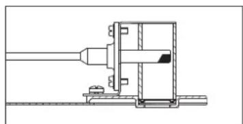
| Fault Possible cause Remedy of whom | |||
| Indicator lamp for protection against calcification (H) glows | The softener is over. Refill the softer | ner. Operator | |
| Inadequate or no flow of de-tergent | Dosing valve to position "0". | Adjusting the detergent metering valve. | Operator |
| Detergent filter blocked or tank is empty. | Clean and/or refill. Operator | ||
| Detergent suction hoses, detergent metering valve or detergent sole-noid valve are leaky or blocked. | Check, clean. Operator | ||
| Electronics or solenoid valve is defective. | Replace Customer Service | ||
| Full pressure does not build up in the appliance | Flushed the nozzle. Replace the nozzle. Operator | ||
| Detergent tank is empty. Refill deter- gent. Operator | |||
| Not enough water | Ensure adequate water supply. | Operator | |
| Sieve at the water inlet is blocked. | Check, dismantle sieve and clean it. | Operator | |
| Leaky detergent dosing valve. | Check and seal it. | Operator | |
| Leaky detergent hoses. | Replace Operator | ||
| Swimmer valve is jammed. | Check and ensure that it moves freely. | Operator | |
| Safety valve is leaky. | Check the setting; install new washers, if re-quired. | Customer Service | |
| Flow valve is leaky or has been set at a low value. | Check valve parts; replace damaged parts; clean the dirt. | Customer Service | |
| Solenoid valve for pressure release is defective. | Replace solenoid valve. | Customer Service | |
| High pressure pump is knocking; manometer is swaying wildly | Vibration dampener is defective. | Replace vibration dampener. | Customer Service |
| Water pump does not suck in ade-quate air. | Check suction system and remove leaks. | Operator | |
| Device continuously turns on and off while hand spray gun is open | Nozzle in spray pipe is blocked. | Check, clean. Operator | |
| Appliance is decalcified. | See section "Descending". | Operator | |
| Switching point of the over-current monitor has got shifted. | Get somebody to reset the over-current monitor. | Customer Service | |
| Sieve blocked in the water shortage safe guard. | Check, dismantle sieve and clean it. | Operator | |
| Appliance does not switch off when the hand-spray gun is closed | The pump has not been fully vent-ed. | Set the machine switch to "0" and pull the hand-spray gun until no fluid comes out of the nozzle. Turn on the appliance again. Repeat this procedure until the full operating pressure is reached. | Operator |
| Safety valve or safety valve washer is defective. | Replace the safety valve and/or the washer. | Customer Service | |
Accessories
Detergent
Detergents simplify the cleaning tasks. The table gives a selection of detergents. Please read the instructions on the packaging carefully before working with any detergents.
| Area of application | Dirt, type of application | Detergent | pH value (approx.) 1 %-solution in tap water |
| Vehicle dealers, fuel stations, freight forwarders, car pools | Dust, street dirt, mineral oils (on painted areas) | RM 55 ASF ** 8 | |
| RM 22/80- Powder ASF 12/10 | |||
| RM 81 ASF 9 | |||
| RM 803 ASF 10 | |||
| RM 806 ASF 11 | |||
| Vehicle protection RM 42 Cold wax | for high-pressure cleaners 8 | ||
| RM 820-Hot wax ASF 7 | |||
| RM 821-Wax spray ASF 6 | |||
| RM 824-Super pearl wax ASF 7 | |||
| RM 44 Rim cleaning gel | 9 | ||
| Metal-processing industry | Oils, greases, dust and similar impurities and dirt | RM 22- Powder ASF | 12 |
| RM 55 ASF 8 | |||
| RM 81 ASF 9 | |||
| RM 803 ASF 10 | |||
| RM 806 ASF 12 | |||
| RM 31 ASF (for stronger dirt) | 12 | ||
| RM 39- liquid (with anti-corrosion agents) | 9 | ||
| Food-processing units | Light to heavy dirt, greases/ oils, large areas | RM 55 ASF 8 | |
| RM 81 ASF 9 | |||
| RM 882 Gel foam OSC | 12 | ||
| RM 58 ASF (Foam detergent) | 9 | ||
| RM 31 ASF * | 12 | ||
| smoke resin | RM 33 * | 13 | |
| Cleaning and disinfection | RM 732 | 9 | |
| Disinfection | RM 735 | 7...8 | |
| Chalk, mineral deposits | RM 25 ASF * | 2 | |
| RM 59 ASF (Foam cleaning) | 2 | ||
| Sanitary area *** | Chalk, stone, soaps, etc. | RM 25 ASF * (basic cleaning) | 2 |
| RM 59 ASF (Foam cleaning) | 2 | ||
| RM 68 ASF 5 |
- = only for short use, two-step method, rinse with clean water ** = ASF = easy-to-dispose *** = Foam-Star 2000 is best suited for initial spraying
Installing the plant
Only for authorised technicians!
General
- The heating appliance of the machine is an ignition plant.
Please follow the local regulations while installing it.
- Use only certified chimneys/exhaust pipes.
Replace high pressure nozzle with steam nozzle if working temperature is above 100 °C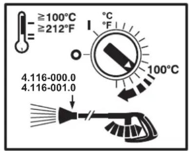
△DANGER
Scalding danger! This symbol must be attached at every tapping point.
Fuel tank for heater
While installing a fuel tank for the heating oil in the machine installation room, please follow the regulations applicable to the storage of inflammable fluids (can be acquired from Carl Heymanns Verlag, Cologne, www.heymanns.com).
Fuel pipes
Please follow the diagram given below for laying the fuel pipes. It is necessary to provide a two-channel system - for the forward and backward flow.
Maximum starting pressure of the fuel: 0.05 MPa (0.5 bar) Maximum under-pressure between fuel filter and pump: 0.04 MPa (0.4 bar)
Suction pipe length in m
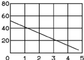
Suction height in m
Possible suction pipe length in pipes with NW 8
Smoke pipe
- Each appliance must be connected to a separate chimney.
- The exhaust system must be designed according to the local rules and regulations after consulting the concerned chimney expert.
We recommend the installation of a draught interceptor between the plant and the chimney.
Note: The chimney draught specifications given in the technical data must be maintained if you want to achieve the prescribed combustion values.
Wall mount
Before installing, please check the load-bearing capacity of the wall. The fastening material delivered with the plant is suitable for concrete walls. Use suitable anchor plugs and screws for hollow component walls, brick walls and gas concrete walls - for e.g. injection anchor (for drilling diagram see the specifications sheet).
Figure 3 - items 19 and 23
The appliance should not be directly attached to the network of water and high pressure pipes. It is mandatory to install the connecting hoses.
Figure 3-A
A shut-off tap must be installed between the main water supply and the connecting hose.
Installing the high pressure connections
All national laws and regulations about installation of electrical appliances must also be followed when installing high pressure lines.
- The pressure loss in the pipe connections must lie below 1.5 MPa.
- The completed pipe connections must be checked using 28 MPa.
- The insulation of the pipes must be resistant to temperatures until 155°C.
Install the detergent tank
Figure 3 - Pos. 20
The tanks are to be installed in such a way that the lower level mirror of the detergent should not be more than 1.5 m under the machine floor and the upper level mirror should not be located above the machine floor.
Water supply
Figure 3 - B and item 19
The water inlet is to be connected to the main water supply using an appropriate water hose. - The water supply must have a minimum output of 1300 l/h at minimum 0.1 MPa. - The water temperature must lie below 30°C.
Electrical connection
ATTENTION
The highest allowed net impedance at the electrical connection point (refer to technical data) is not to be exceeded. In case of confusion regarding the power impedance present on your connection, please contact your utilities provider. Note: Operating procedures create short term power sinkings. During unfavorable net conditions other devices might be disturbed.
- For connection values, see technical data and type plate.
- The electrical connections must be done by an electrician according to IEC 60364-1.
- Current-carrying parts, cables and appliances in the working area must be installed in a defectless state and must be protected against water sprays.
DANGER
To avoid accidents due to electrical faults we recommend the use of sockets with a line-side current-limiting circuit breaker (max. 30 mA nominal tripping current).
Firmly installed electrical connection
Establish the electrical connection.
A main switch that can be locked (figure 3 - item 6) is to be installed at a safe and easily accessible place to switch off the stationary high pressure cleaner.
The contact opening of the main switch must be at least 3 mm.
Electrical connection with plug/socket
Install the Cekon plug on the connection cable of the appliance. Insert the Cekon plug into the socket.
To switch off the stationary high-pressure cleaner, the Cekon plug must be easily accessible so that it can be removed from the mains.
Initial startup
Before using for the first time, cut off the tip of the lid of the oil tank on the water pump.
Measures to be taken before start-up
DANGER
Risk of explosion! Only refill with diesel oil or light fuel oil. Unsuitable fuels, e.g., petrol, must not be used.
Refill the fuel tank.
ATTENTION
Hot water operations without fuel will cause damage to the fuel pump. Ensure adequate fuel supply before starting hot water operations.
Figure 3 - Pos. 14
Note: The EASY!Lock system joins components with a quick-fasten thread solidly and securely with just one turn.
Connect the high-pressure hose with the hand-spray gun and the spray pipe, and connect it to the high-pressure outlet of the appliance or the high-pressure pipe network.
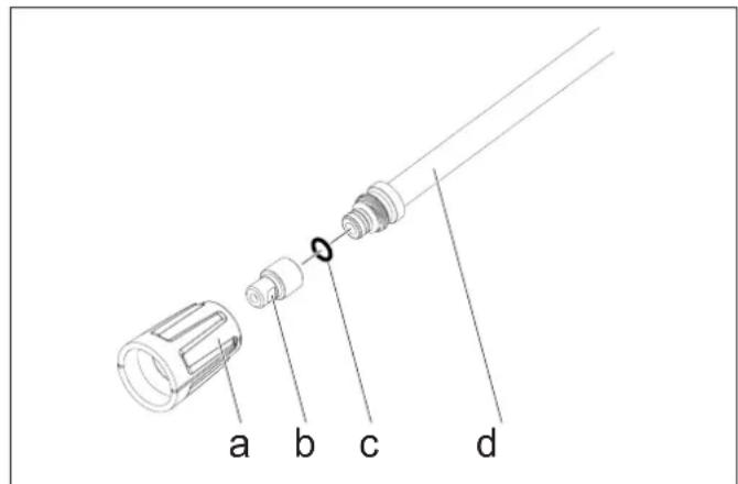
Fasten the nozzle mouth-piece (b) with the union nut (a) on the spray pipe (d). Please ensure that the sealing ring (c) is cleanly positioned in the nut.
Anti-calcification measures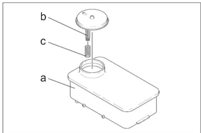
Remove spring (c) from the lid support (b) of the softener tank (a). Fill the tank with Kaercher softener liquid RM 110 (Order no. 2.780-001).
DANGER
Dangerous electrical voltage! Setting may only be done by an electrician.
Determining the hardness of tap water: - through the public water supply works, using a hardness tester (order no. 6.768-004). Remove the appliance cover. Open the switch box at the operating panel.
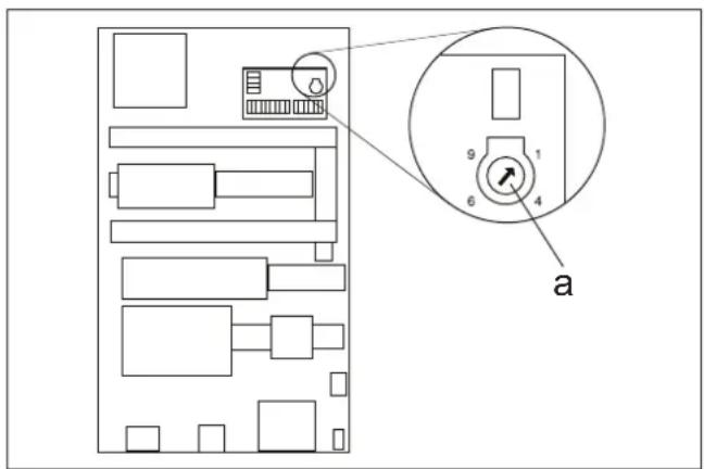
Set the speed potentiometer (a) according to the water hardness. You can refer to the correct setting in the table.
Example:
For a water hardness of 15°dH set 6 on the value scale of the speed potentiometer. This results in a pause of 31 seconds, i.e. the solenoid valve will open briefly every 31 seconds.
| Water hardness (°dH) 5 10 1 | 5 20 25 | ||||
| Scale on the speed potentiometer | 8 | 7 | 6 | 5 | 4 |
| Pause (in seconds) 50 40 31 | 22 16 | ||||
Adjusting the operations stand-by time
The operations stand-by time is set on the larger plate on the left side-wall of the electrical cabinet.
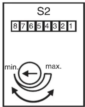
The operations stand-by time is set in the factory to a minimum time of 2 minutes and can be increased to a maximum time of 8 minutes.
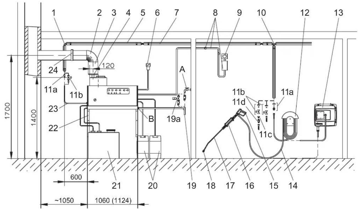
Figure 3
| Item: Installation material Order No. | ||
| 1 Threaded elbow joint 6.386-356 | ||
| 2 Smoke pipe bender 90° 7.234-605 | ||
| 3 Smoke pipe 7.234-603 | ||
| 4 Draught interceptor for smoke HDS 9/14-4 4.656 | -080 | |
| Draught interceptor for smoke HDS 12/14-4 | 4.656-079 | |
| 5 Thermal insulation 6.286-114 | ||
| 6 Main switch 6.631-455 | ||
| 7 Set of pipes, galvanised steel 2.420-004 | ||
| Set of pipes, stainless steel 2.420-006 | ||
| 8 Remote control set | 2.744-008 | |
| 9 Set of parts for emergency-stop switch | 2.744-002 | |
| 10 | T-screws | 6.386-269 |
| 11a | Connection neck, brass 2.638-180 | |
| Connection neck, stainless steel | 2.638-181 | |
| 11b | Shut-off valve NW 8, galvanised steel | 4.580-144 |
| Shut-off valve NW 8, stainless steel | 4.580-163 | |
| 11c | Fixed part for quick coupling | 6.463-025 |
| 11d | Loose part for quick coupling | 6.463-023 |
| Item: Installation material Order No. | ||
| 12 | Hose holder | 2.042-001 |
| 13 | Hose drum | 2.637-238 |
| 14 | High-pressure hose EASY!Lock 10 m Connections 2x TR) | 6.110-038 * |
| 15 | Trigger gun EASY!Force | 4.118-005 |
| Speed regulator HDS 9/14-4 | 4.118-008 | |
| Speed regulator HDS 12/14-4 | 4.118-009 | |
| 16 | Spray pipe holder | 2.042-002 |
| 17 | Spray lance EASY!Lock | 4.112-012 |
| 18 | Nozzle mouth-piece HDS 9/14-4 | 2.113-026 |
| Nozzle mouth-piece HDS 12/14-4 | 2.113-015 | |
| 19 | Water pipes | 4.440-282 |
| 19a | Solenoid valve for water inlet | 4.743-011 |
| 20 | Detergent tank, 60 I | 5.070-078 |
| 21 | Tank for heating oil, 600 I | 6.392-050 |
| 22 | Set of parts for wall console | 2.053-005 |
| Set of parts for floor frame | 2.210-008 | |
| 23 | High-pressure hose EASY!Lock 1.5 m (connections TR - M22x1.5) | 6.110-068 |
| High-pressure hose EASY!Lock 1.5 m (connections 2x TR) | 6.110-024 * | |
| 24 | Pipe clip | 6.373-374 |
- Adapter TR - M22x1.5 (4.111-030) required
EU Declaration of Conformity
We hereby declare that the machine described below complies with the relevant basic safety and health requirements of the EU Directives, both in its basic design and construction as well as in the version put into circulation by us. This declaration shall cease to be valid if the machine is modified without our prior approval.
Product: High pressure cleaner with steam stage
Type: 1.698-xxx
Type: 1.699-xxx
Relevant EU Directives
2014/68/EU
2006/42/EC (+2009/127/EC)
2014/30/EU
Component category
II
Conformity procedure
Module H
Heating coil
Conformity assessment Module H
Safety valve
Conformity assessment Art. 4 para 3
control block
Conformity assessment Module H
various pipes
Conformity assessment Art. 4 para 3
Applied harmonized standards
EN 55014-1: 2006+A1: 2009+A2: 2011
EN 55014-2: 2015
EN 60335-1
EN 60335-2-79
EN 61000-3-2: 2014
HDS 12/14:
EN 61000-3-3:2013
HDS 9/14:
EN 61000-3-11:2000
Applied specifications:
Based on AD 2000
Based on TRD 801
Name of the appointed agency:
for 2014/68/EU
The signatories act on behalf of and with the authority of the company management.
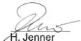
Chairman of the Board of Management
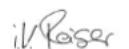
S. Reiser
Director Regulatory Affairs & Certification
Documentation supervisor:
S. Reiser
Alfred Karcher SE & Co. KG
71364 Winnenden (Germany)
Tel.: +49 7195 14-0
Fax: +49 7195 14-2212
Winnenden, 2018/10/01
Warranty
The warranty terms published by the relevant sales company are applicable in each country. We will repair potential failures of your appliance within the warranty period free of charge, provided that such failure is caused by faulty material or defects in manufacturing. In the event of a warranty claim please contact your dealer or the nearest authorized Customer Service centre. Please submit the proof of purchase.
Customer Service
| Plant type: Manufact. no.: Start-up on: | ||
Testing done on:
Findings:
Signature
Testing done on:
Findings:
Signature
Testing done on:
Findings:
Signature
Testing done on:
Findings:
Signature
Note: The recommended testing frequencies of the respective statutory regulations of the country of operation are to be followed.
Recurring tests
| Testing done by: External testing Internal testing Leak-proof tests | |||
| Name Signature of the authorised | person/ date | Signature of the authorised person/ date | Signature of the authorised person/ date |
| Name Signature of the authorised | person/ date | Signature of the authorised person/ date | Signature of the authorised person/ date |
| Name Signature of the authorised | person/ date | Signature of the authorised person/ date | Signature of the authorised person/ date |
| Name Signature of the authorised | person/ date | Signature of the authorised person/ date | Signature of the authorised person/ date |
| Name Signature of the authorised | person/ date | Signature ofthe authorised person/ date | Signature of the authorised person/ date |
| Name Signature of the authorised | person/ date | Signature of the authorised person/ date | Signature of the authorised person/ date |
| Name Signature of the authorised | person/ date | Signature of the authorised person/ date | Signature of the authorised person/ date |
| Name Signature of the authorised | person/ date | Signature of the authorised person/ date | Signature of the authorised person/ date |
| name Signature of the authorised | person/ date | Signature of the authorised person/ date | Signature of the authorised person/ date |
| Name Signature of the authorised | person/ date | Signature of the authorised person/ date | Signature of the authorised person/ date |
| Name Signature of the authorised | person/ date | Signature of the authorised person/ date | Signature of the authorised person/ date |
| Name Signature of the authorised | person/ date | Signature of the authorised person/date | Signature of the authorised person/ date |

www.kaercher.com/REACH
Hazard level
DANGER
2006/42/EC (+2009/127/EC)
2014/30/EU
H.Jenner
Chairman of the Board of Management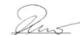
S. Reiser Director Regulatory Affairs & Certification
Responsible for documentation:
S. Reiser
Alfred Kärcher SE & Co. KG
Alfred-Karcher-Straße 28-40
71364 Winnenden (Germany)
Tel.: +49 7195 14-0
Fax: +49 7195 14-2212
Winnenden, 2018/10/01
Warranty
www.kaercher.com/REACH
Hazard levels
DANGER
2006/42/EC (+2009/127/EC)
2014/30/EU
Chairman of the Board of Management
S. Reiser
Director Regulatory Affairs & Certification
71364 Winnenden (Germany)
Tel.: +49 7195 14-0
Fax: +49 7195 14-2212
Winnenden, 2018/10/01
Warranty
www.kaercher.com/REACH
Hazard level
DANGER
Overflow protection
Strainer in water supply
Chairman of the Board of Management
Director Regulatory Affairs & Certification
71364 Winnenden (Germany)
Tel.: +49 7195 14-0
Fax: +49 7195 14-2212
Winnenden, 2018/10/01
Warranty
www.kaercher.com/REACH
Danger levels
△DANGER
2006/42/EC (+2009/127/EC)
2014/30/EU
Chairman of the Board of Management
S. Reiser
Director Regulatory Affairs & Certification
Documentation manager:
S. Reiser
Alfred Karcher SE & Co. KG
71364 Winnenden (Germany)
Tel.: +49 7195 14-0
Fax: +49 7195 14-2212
Winnenden, 2018/10/01
Warranty
www.kaercher.com/REACH
Hazard levels
DANGER
2006/42/EC (+2009/127/EC)
2014/30/EU
Module category
II
Chairman of the Board of Management
Director Regulatory Affairs & Certification
71364 Winnenden (Germany)
Tel.: +49 7195 14-0
Fax: +49 7195 14-2212
Winnenden, 2018/10/01
Warranty
www.kaercher.com/REACH
Faregrader
△FARE
Symbol "Motor taend"
Symbol "Braender taend"
2006/42/EF (+2009/127/EF)
2014/30/EU
Koponentkategori
II
Overensstemmelsesproceduren
Modul H
Varmeslange
Overensstemmelsesafprovning modul H
Sikkerhedsventil
Chairman of the Board of Management
S. Reiser
Director Regulatory Affairs & Certification
71364 Winnenden (Germany)
Tel.: +49 7195 14-0
Fax: +49 7195 14-2212
Winnenden, 2018/10/01
Guarantee
www.kaercher.com/REACH
Risk level
△FARE
2006/42/EC (+2009/127/EC)
2014/30/EU
Category of components
II
Conformity assessment
Module H
Heating hose
Conformity assessment Module H
Safety valve
Conformity assessment Art. 4 para. 3
Control block
Conformity assessment Module H
Various hoses
Conformity assessment Art. 4 para. 3
Applied harmonized standards
EN 55014-1:2006+A1:2009+A2:2011
EN 55014-2: 2015
EN 60335-1
EN 60335-2-79
EN 61000-3-2: 2014
HDS 12/14:
EN 61000-3-3:2013
HDS 9/14:
EN 61000-3-11:2000
Chairman of the Board of Management
S. Reiser Director Regulatory Affairs & Certification
71364 Winnenden (Germany)
Tel.: +49 7195 14-0
Fax: +49 7195 14-2212
Winnenden, 2018/10/01
Garanti
Adjust standby period
Chairman of the Board of Management
S. Reiser
Director Regulatory Affairs & Certification
Documentation authorized representative:
S. Reiser
Alfred Karcher SE & Co. KG
71364 Winnenden (Germany)
Tel.: +49 7195 14-0
Fax: +49 7195 14-2212
Winnenden, 2018/10/01
Warranty
www.kaercher.com/REACH
Hazard levels
DANGER
Chairman of the Board of Management
S. Reiser
Director Regulatory Affairs & Certification
71364 Winnenden (Germany)
Tel.: +49 7195 14-0
Fax: +49 7195 14-2212
Winnenden, 2018/10/01
Takuu
www.kaercher.com/REACH
Danger levels
DANGER
Indicates an imminent danger that can lead to serious or fatal injuries.
WARNING
Indicates a potentially dangerous situation that can lead to serious or fatal injuries.
CAUTION
Indicates a potentially dangerous situation that can lead to minor or slight injuries.
CAUTION
Indicates a potentially dangerous situation that can lead to property damage.
Symbols on the device

The device must not be disposed of with household waste. It
EN 55014-1:2006+A1:2009+A2:2011
EN 55014-2: 2015
EN 60335-1
EN 60335-2-79
EN 61000-3-2: 2014
HDS 12/14:
EN 61000-3-3: 2013
HDS 9/14:
EN 61000-3-11:2000
Chairman of the Board of Management
Director Regulatory Affairs & Certification
YTeUbuvos Eyypawv TKunpiwns:
S. Reiser
Alfred Karcher SE & Co. KG
71364 Winnenden (Germany)
Tel.: +49 7195 14-0
Fax: +49 7195 14-2212
Winnenden, 2018/10/01
Eyyunon
www.kaercher.com/REACH
Hazard levels
△DANGER
Chairman of the Board of Management
S. Reiser
Director Regulatory Affairs & Certification
71364 Winnenden (Germany)
Tel.: +49 7195 14-0
Fax: +49 7195 14-2212
Winnenden, 2018/10/01
Warranty
www.kaercher.com/REACH
DANGER
DANGER
Indication of an imminent threat that will lead to severe injuries or even death.
WARNING
Indication of a potentially dangerous situation that could lead to severe injuries or even death.
CAUTION
Indication of a potentially dangerous situation that could lead to minor injuries.
ATTENTION
Indication of a potentially dangerous situation that could lead to property damage.
Symbol on the device

High-pressure water jets can be dangerous if used improperly.
It is forbidden to direct the jet at people, animals, live electrical equipment, or the unit itself.

Danger of burns from hot surfaces!
General safety information
The relevant national regulations for working with high-pressure jet units must be observed. The relevant national safety regulations must be observed. The high-pressure jet units must be checked regularly and the checks must be documented in writing. The heating device of the unit is switched on automatically. The high-pressure units must be checked regularly, observing the relevant national regulations. - When operating the unit in rooms, the safety of the exhaust gases must be ensured (a vent without interruption for the exhaust gas is required). Furthermore, an adequate supply of fresh air must be ensured. According to the applicable national requirements, high-pressure units are operated for commercial use only by trained personnel. KARCHER company specialists carry out the commissioning process and train and document this process. The documentation can be obtained by sending a request to the KARCHER company partner. When requesting the documentation, the part number and serial number of the unit must be specified. We are responsible for ensuring that, according to the applicable national requirements, the unit is checked periodically by trained personnel. Please contact the KARCHER company partner. The safety instructions for the cleaning agents used must be observed (usually given on the packaging label). Any modifications to the device/accessories are prohibited.
Local regulations and directives
Before installation, coordination with a ventilation specialist is required.
During installation, the provisions of building law, industrial law, and environmental protection must be observed. The regulations and directives listed below apply:
- According to the national regulations, the unit may only be installed by a specialized company. - For electrical installation, the relevant national regulations must be observed.
- Settings, maintenance, and repair of the burner may only be carried out by trained technicians from the KARCHER service department. - When designing the exhaust gas pipe, the applicable local state regulations must be observed.
Workstations
The main workstation is at the control panel. Other workstations, depending on the design of the unit, are located at the additional equipment (spray gun), which are connected to the connection points.
Personal protective equipment

When working on parts that amplify sound, appropriate hearing protection must be worn to prevent hearing damage.
To protect against splashing water and chemicals, suitable protective clothing and safety goggles must be worn.
Operating manual
The tool is designed to remove dirt from surfaces using a freely exiting air stream. In particular, it is used for cleaning machines, automobiles, and building facades.
DANGER
Danger of injury! When used at gas stations or in other hazardous areas, the relevant safety regulations must be observed.
Please do not allow standing water containing mineral oils to enter the soil, groundwater, or sewage systems. Therefore, motor and vehicle washing should only be carried out in designated areas with an oil separator.
Water quality requirements:
ATTENTION
Only clean water may be used as the high-pressure medium. Contamination leads to premature wear of the device and accessories and to the formation of deposits in them.
If water is reused, it must not exceed the following limit values.
18 High-pressure hose EASY!Lock
Control panel
Fig. 2 A Device switch B Temperature regulator C Rinsing agent valve I D Rinsing agent valve II (optional equipment)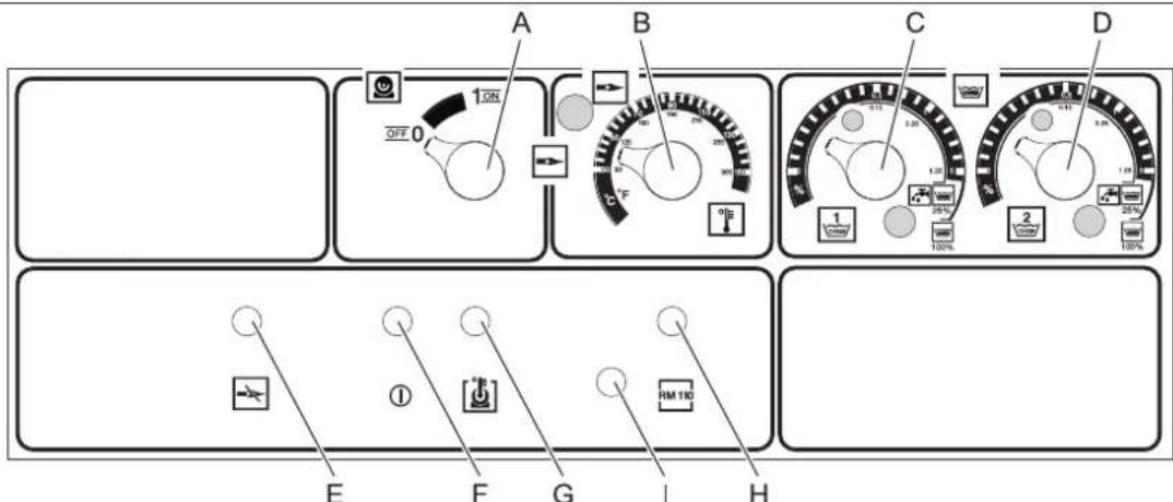
E Fault indicator lamp for burner
F Indicator lamp for operational readiness
G Indicator lamp for engine overheating
Control lamp for scale protection
Knob for adjusting the burner power
Commissioning
WARNING
Danger of burns! The device, accessories, connecting lines and connecting elements must be in perfect condition. If the condition is not satisfactory, do not use the device.
Connection to power supply
- Connection parameters are indicated on the factory plate and in the "Technical data" section. Electrical connection must be carried out by an electrician and comply with IEC 60364-1 standards.
Operation
DANGER
Explosion hazard! Do not operate in explosive atmospheres.
DANGER
Danger of burns! Never use the device without the installed water hose. Check the tightness of the water hose fixation before each use. Tighten the threaded connection of the water hose firmly by hand.
DANGER
Danger of burns! During operation, hold the spray gun and the water hose with both hands.
DANGER
Danger of injury! During operation, blocking of the trigger safety lever is permitted.
DANGER
Danger of injury! If the safety lever is damaged, contact the service department.
Safety instructions
The user must use the device in accordance with its intended purpose. They must take into account local conditions and pay attention when working with the device on other units located nearby.
Preparing the device for operation
DANGER
Danger of injury from escaping jet, hot water!
DANGER
Before starting work with high-pressure hoses, always check for damage. Damaged high-pressure hoses must be replaced immediately.
→ Before each use, check the high-pressure hose, piping, fittings, and nozzle for damage. → Check connection points for leaks and tightness.
ATTENTION
Danger of damage when working dry.
→ Check the level of the cleaning agent and top up if necessary. Check the level of the rinsing liquid and top up if necessary.
Switch off in case of an emergency situation
Turn the spray gun (A) to the OFF position. Close the water supply. Press the spray gun trigger until the appliance is relieved of pressure.
Adjusting the operating pressure and output rate
Settings on the appliance
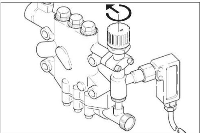
→ Turning the capacity adjustment valve clockwise increases the working pressure and output rate. → Turning the capacity adjustment valve counterclockwise reduces the working pressure and output rate.
Setting the pressure/quantity regulator on the manual spray gun (optional)
DANGER
Danger of injury! While adjusting the pressure/quantity regulator, make sure that the threaded connection of the spray lance does not loosen.
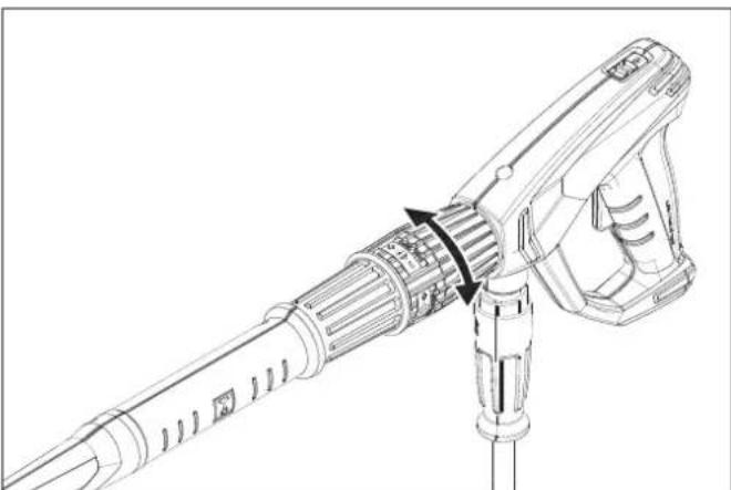
→ Turning the quantity regulator to the right increases the spray rate and raises the working pressure. → Turning the quantity regulator to the left reduces the spray rate and lowers the working pressure.
Working with cold water
Open the water supply.

Operation with hot water
DANGER
Danger of burns!
CAUTION
Operating in hot water mode without fuel supply will damage the fuel pump. Before working in hot water mode, ensure fuel supply. If necessary, connect the burner.

Cumeon《Topenka EKnIOyeHa》
Set the appliance switch (A) to the "Burner ON" position. Set the required water temperature using the temperature regulator (B). The maximum possible temperature is 98 °C.
Steam operation
DANGER
Danger of burns! At working temperatures above 98 °C, the working pressure must not exceed 3.2 MPa (32 bar). To switch the appliance from hot water mode to steam mode, it is necessary to cool down and switch off the appliance. The switchover must be carried out as follows:
Replace the high-pressure nozzle with a steam nozzle (optional equipment).
| № 3aka3a: Tyn | |
| 4.116-000 HDS 9/14 | |
| 4.116-001 HDS 12/14 |
Set the steam temperature to 150 °C.
Without pressure/quantity regulator on the manual spray gun
Set the delivery regulating valve on the high-pressure pump to the minimum water flow (turn counterclockwise).
With pressure/quantity regulator on the manual spray gun (optional)
Set the delivery regulating valve on the high-pressure pump to the maximum water flow (turn clockwise). Then set the water flow regulator on the manual spray gun to the minimum water flow, turning it to the left.
Readiness for operation
- If the manual spray gun is closed during operation, the device switches off. When the gun is opened again within the set readiness time (2...8 minutes), the appliance starts up automatically.
- If the readiness time has elapsed, the circuit with time mechanism and blocking will switch off the pump and burner. The readiness indicator lamp (F) goes out. To restart, set the appliance switch to "0" and then switch on again. If the appliance is operated with remote control, the restart button can be activated via the corresponding switch on the remote control panel.
Nozzle selection
- The covers may only be sprayed when using the flat fan nozzle (25°) with a minimum spraying distance of 30 cm. Never spray the covers with a round jet.
The following nozzles are used for the high-pressure cleaner:
| Заграз-нени | Насада | Угол раз-брызг-ваши | № detani | Давли- нце [Mпа] | Отдана [H] |
HDS 9/14
| сильhoe 0°0060 0°5 | 765-240 | 14 | 44 | |
| срдnev 2°5060 25° | 5.76 | 5-027 | ||
| лergкoe 40060 40° | 5.1 | 30-087 |
HDS 12/14
| сильhoe 00080 0° 5 | 765-243 | 14 | 55 | |
| средneas 25080 25° | 5.76 | 5-061 | ||
| лergкoe 40080 40° | 5.7 | 65-221 |
For hose lengths over 20 m or when using a high-pressure hose with a nominal internal diameter of 8 or more than 2 x 10 m, it is necessary to use the following nozzles:
| Заграз-нени | Hасада | Угол паз-6рьлзи-Bаня | № детали | Давли-нце-[Mпа] | Одача[H] |
| HDS 9/14 | |||||
| синьhoe 0 | 075 | 0° 5.765-24° | 10 | 37 | |
| средеме 2 | 575 | 25° 5° | 765-057 | ||
| пегкoe | 4075 | 40° | 5.765-220 | ||
Dosing of cleaning agent
- Using the cleaning agent simplifies the cleaning process. Cleaning agents are fed from an external tank for cleaning agents. - In the basic version, the device is equipped with a dosing valve (C). A second dosing device (dosing valve D) can be ordered as special additional equipment. This allows the use of two different cleaning agents. - The dosing quantity is set on the dosing valve for cleaning agent (C or D). The set value corresponds to the dose of cleaning agent in percent.
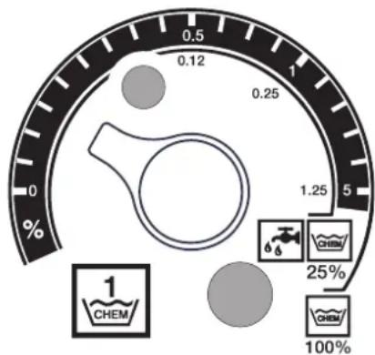
- The external dosing works when using undiluted cleaning agent (100% CHEM). - The internal dosing works when using cleaning agent previously diluted in a ratio of 1:3 (25% CHEM + 75% water).
The following table shows the consumption values of the cleaning agent in relation to the readings on the upper scale.
| HDS 9/14 | |||
| Посложения | 0,5 | 1 | 5 |
| Количесво моюцero сретсва [и/ч] | 14...15 2 | 2...24 50 | |
| Концентрацnia моюцero сретсва [%] | 1,5 | 2,5 | 5 |
HDS 12/14
| Посложения | 0,5 | 1 | 5 |
| Количесво моюшero средства [Л/у] | 10...13 | 23...27 | 60 |
| Концентрацnia моюшero средства [%] | 1 | 2 | 5 |
The accuracy of the dosing quantity setting depends on: - Viscosity of the cleaning agent - Suction height - Hydraulic resistance of the high-pressure hose.
If it is necessary to top up, the amount of cleaning agent drawn in must be measured (e.g., by suction from a measuring cup).
Note: Recommendations for the use of cleaning agents are given in the chapter "Additional equipment".
Filling the detergent tank
ATTENTION
The heater may become covered with scale if used without water softening.
In an empty tank with softened water, the anti-scale control lamp (H) lights up.
Fig.1-103.9
→Fill the tank with softened water RM110 (2.780-001).
Shutdown
△DANGER
Danger of scalding with hot water! After use with hot water, the device must be operated with the cold water supply open for at least two minutes.
After use, rinse with cleaning agent
In hot water mode, set the temperature regulator (B) to the lowest temperature. →Let the device run for 30 seconds without cleaning agent.
Switching off the appliance
Turn the appliance switch (A) to the "0" position and close the water tap. Press the spray trigger until the appliance is free of pressure. Lock the spray trigger with the safety lock to prevent accidental pressing.
Shutdown
During long breaks in operation, if there is no possibility of storing the device in a frost-free place, carry out the following measures (see chapter "Maintenance and care", section "Frost protection").
→ Drain the water. →Rinse the device with antifreeze. →Switch off, lock the main switch and disconnect the plug from the socket.
Storage
CAUTION
Danger of injury and damage! When storing, pay attention to the weight of the device.
Transport
WARNING
During transport, ensure protection of the trigger from damage.
CAUTION
Danger of injury and damage! When transporting, pay attention to the weight of the device.
When transporting the device in transport vehicles, the applicable local government regulations aimed at protection against slipping and tipping must be observed.
Technical data
The system must be equipped with two lines: supply line and return line.
- Maximum pre-pressure of liquid fuel: 0.05 MPa (0.5 bar) - Maximum vacuum between fuel filter and pump: 0.04 MPa (0.4 bar)
Suction pipe length in meters (m)
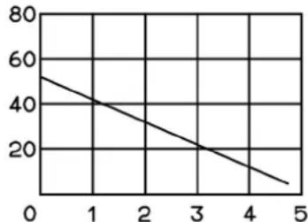
Delivery head in meters (m)
Possible suction pipe length when using pipes with nominal internal diameter NW 8
Flue gas pipe
The gas pipe must be connected to the appliance's own gas pipe. The gas appliance must be installed in accordance with local regulations and in agreement with a competent ventilation specialist.
We recommend installing a shut-off valve between the appliance and the gas pipe.
Note: To achieve the prescribed combustion parameters, it is necessary to adhere to the flue gas values specified in the "Technical Data" section.
Wall-mounted installation
- Before installation, check the load-bearing capacity of the wall. The mounting materials included in the delivery kit are suitable for this appliance. For walls made of hollow brick or lightweight concrete, it is necessary to use anchors that pass through the wall, for example, expansion anchors (see the hole layout diagram on the dimensional drawing).
Fig. 3 - pos. 19 and 23
The appliance must not be rigidly connected to the water supply or to high-pressure gas pipelines. It is mandatory to use flexible connections.
Fig. 3 - A
Provide a shut-off valve between the water supply and the flexible connection.
Installation of high-pressure hoses
When installing high-pressure hoses, the relevant national standards must be observed.
The pressure in the gas pipeline must be less than 1.5 MPa. The prepared gas pipeline must be tested at a pressure of 28 MPa. The insulation of the gas pipeline must be resistant to temperatures up to 155°C.
Installation of detergent tanks
Fig. 3 - 10, 3.20
The tank must be installed in such a way that the lower level of the detergent is no more than 1.5 m below the appliance, and the upper level is no higher than the appliance.
PoaaBoBbI
Pnc.3-Bnno3.19
→ BoDocnyck noKlnHouaETcK BOOpnpoBOHOcETn npn nomOu nnoXoJzero BOJHOrO WnaHra. -ПОНИВОДNTENBHOCTb NOДЧИ BODы ДОЛЖHA COCTABJIb He MeHee 1300 n/aC npn daBneHn He MeHee 0,1 mPa. - Tempepatya BOdi DoJnxHa 6bItb Hnke 30°C
3neKtpnueckoe noDcoeHHeHne
BHIMAHHE
PpebueHue MaKcumalbHo donycmmuOo nonho2o conpomueHeu cemu 6 moKe 3neKmpuueckoO noDknIOeHua (cm. pa3- den "Texhueckue daHHie") He donyckaemc. B mom cnUyae, ecnu bAm He u3BeCmHa beenuHa nIHOzo cnpomueHeu cemu 6 moKe 3neKmpuueckoO noDknIOeHua, obpamumecb 6 3hep2oCha6kaiouyo opaunu3auuio.
Yka3aHHe: PpoceCbI BKNIOeHnO C03daOT KpaTKe NaDeHnHaNpRAKeHn. B Cnyuae HEnCnpaBHOcTe 3JIeKTPoCeTu BO3MOxHbI NOMEXI B pa6oTe dpynx np6opOB.
- NapametpbI NOKJIIOUeHn yka3aHbI Ha 3abOdCKoT abNueKe nB pa3dene "TexHnueckne daHHble". -3NeKTPnueeCKO INKIOHHe HNOXHO npoBOuNTbCra 3NeKTPNKOM I COOTBeTCTBOBaTb HopMaM IEC 60364-1. ToKoBeNyUne DeTaN, KaBEn I npBOpbI B paOoei 30He DOnJXHbI HaxoNDtCBa B6e3yPpeHOM COCTOAHN I 6bITb 3a- uIuIeHbI OT nonaDaHnBa BOdHOB CTpyN.
ONACHOCTb
Bo u36ekhaue Hecyacmhbix cnyaee, c83aHHbIX c 3neKmpuecmeBOM, Mbl pekomehdyem Ucnoh3oeaueHue po3emok c nped-6kNIOeHHbIM ycpoucmbom 3auumbi om moka nopekdeHua (MaKC.HOMUHAJIbHaCUNa moka cpaabambeaHua:30mA).
KecTKO CMOHTnPOBaHHOe NOcOeHNHeHne K 3JIeKtpNuecko CETn
YCTAHOBINTb 3JIeKTPnueckoe CoeINHeHne.
Дя OTКИЧЕнЯ CTAUNOHAPHON OYHCTNTeHBON YCTAHOBKN BblCOKOTO DAJIENEHA NCOIb3yeTcR 3aIIpaEMbI Ha 3AMOK TnABHBiBbIKNIOuATEb (pnc. 3, no3.6), pacnoIIOXeHHbI B 6e3ONaCHOM INJIERKOIOCTyNHOM MecTe.
山Hpa3MbikAHNOKHTAOBIIaBHOrOBbIKIOaTeIydoJIHKHa coCTaBnTb He MeHee 3 MM.
3NeKtpnueckoe nOcOeINHHeNc C NOMoUbIO WTeKePHoro pa3beMa/po3eTkn
Connect the plug of the device's power cable to the socket. Insert the plug into the outlet.
For stationary installation, the high-pressure plug must be easily accessible for connection to the power supply.
First commissioning
Before first use, remove the cap from the oil filler neck and fill with oil for the high-pressure pump.
Commissioning procedure
DANGER
Explosion hazard! Only use diesel fuel or light heating oil. Using other types of fuel, e.g., gasoline, is prohibited. Fill the fuel tank.
CAUTION
Operating in dry mode without fuel leads to damage to the fuel pump. Before operating in dry mode, ensure fuel supply.
Fig. 3-Item 14
Note: The EASY!Lock system, thanks to its quick-release coupling, allows components to be connected quickly and reliably in just one turn.
Connect the high-pressure hose to the spray gun with the nozzle, then install it on the high-pressure outlet of the device or the high-pressure piping system.
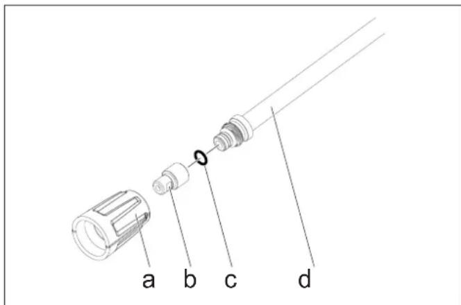
Tighten the nut (a) to secure the nozzle holder (b) on the spray tube (d). Ensure that the seal (c) sits correctly in the groove.
Protection against backflow
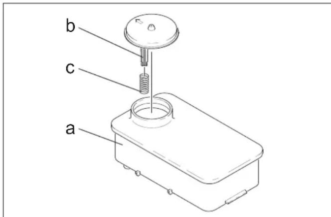
Remove the spring (c) from the support of the lid (b) of the detergent tank (a). Fill the tank with Kärcher RM 110 detergent (order no. 2.780-001).
DANGER
Dangerous electrical voltage! Installation must be carried out only by electricians.
Determining local water hardness: - through the local municipal service company, - with the help of a water hardness measuring device (order no. 6.768-004) → remove the device cover. Open the distribution valve with the control knob.
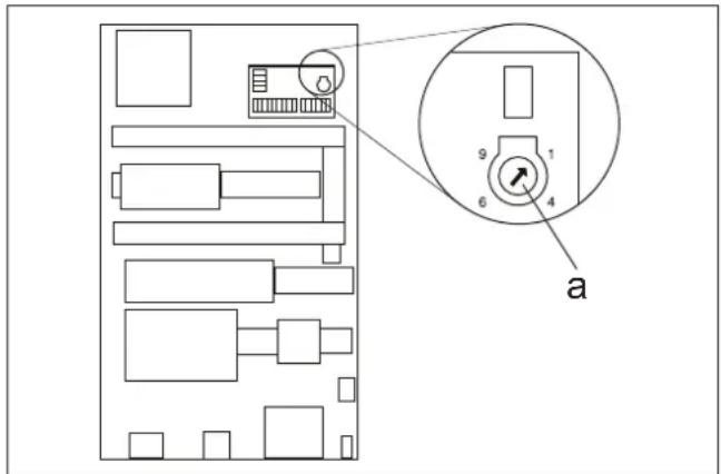
→ Set the rotary potentiometer (a) according to the water hardness. The table shows the correct settings.
Example:
Water hardness 15°dH. Set the rotary potentiometer to position 6. This means that the rinse time is 31 seconds, i.e., every 31 seconds the inlet valve opens briefly.
Assessment of conformity per Art. 4a (3)
Control unit
Assessment of conformity of the device
different pipelines
Assessment of conformity per Art. 4a (3)
Applied harmonized standards
EN 55014-1:2006+A1:2009+A2:2011
EN 55014-2: 2015
EN 60335-1
EN 60335-2-79
EN 61000-3-2: 2014
HDS 12/14:
EN 61000-3-3: 2013
HDS 9/14:
EN 61000-3-11:2000
PpmeHenHbIe CneuNkaun:
AD 2000 no o6pa3u
TRD 801 no o6pa3uy
Ha3BaHHe OTBeTCTBENHO npedCTaBnteNbCTBa:
�� 2014/68/EU
Chairman of the Board of Management
Director Regulatory Affairs & Certification
YIIOHOMOeHHb COtpyDnK IO BedeHNIO DOKymeHToo6oPota: S. Reiser
Alfred Karcher SE & Co. KG
71364 Winnenden (Germany)
Tel.: +49 7195 14-0
Fax: +49 7195 14-2212
Winnenden, 2018/10/01
Warranty
In each country, the warranty conditions issued by our authorized sales organization apply respectively. We will repair any malfunctions of the device free of charge during the warranty period, provided that they are due to material defects or manufacturing errors. In the event of a claim during the warranty period, please contact the sales organization that sold the device or the nearest authorized customer service center, presenting the purchase receipt.
The date of manufacture is indicated by the factory
in the table in coded form.
The digits have
the following meaning:
Example: 30190
3 year of manufacture 0 century of manufacture 1 decade of manufacture 9 second digit of month of manufacture 0 first digit of month of manufacture
Thus, in this example, the code 30190
means the date of manufacture 09/(2)013.
Customer service
www.kaercher.com/REACH
Hazard levels
△DANGER
H. Jenner Chairman of the Board of Management
S. Reiser Director Regulatory Affairs & Certification
71364 Winnenden (Germany)
Tel.: +49 7195 14-0
Fax: +49 7195 14-2212
Winnenden, 2018/10/01
Warranty
www.kaercher.com/REACH
Hazard levels
△DANGER
2006/42/EC (+2009/127/EC)
2014/30/EU
Category module
II
Declaration of Conformity
Module H
Heating hose
Chairman of the Board of Management
S. Reiser Director Regulatory Affairs & Certification
71364 Winnenden (Germany)
Tel.: +49 7195 14-0
Fax: +49 7195 14-2212
Winnenden, 2018/10/01
Warranty
www.kaercher.com/REACH
Hazard levels
DANGER
Relevant EU directives:
2014/68/EU
2006/42/EC (+2009/127/EC)
2014/30/EU
Assembly category
1
Conformity assessment
Module H
Heating coil
Conformity assessment module H
Safety valve
Conformity assessment Art. 4 Para. 3
Control block
Conformity assessment module H
Various pipelines
Compliance assessment Art. 4 Para. 3
Chairman of the Board of Management
S. Reiser
Director Regulatory Affairs & Certification
Authorized person for documentation:
S. Reiser
Alfred Karcher SE & Co. KG
71364 Winnenden (Germany)
Tel.: +49 7195 14-0
Fax: +49 7195 14-2212
Winnenden, 2018/10/01
Warranty
www.kaercher.com/REACH
Hazard levels
DANGER
2006/42/WE (+2009/127/WE)
2014/30/UE
Component category
II
Chairman of the Board of Management
Director Regulatory Affairs & Certification
Documentation administrator:
S. Reiser
Alfred Kärcher SE & Co. KG
71364 Winnenden (Germany)
Tel.: +49 7195 14-0
Fax: +49 7195 14-2212
Winnenden, 2018/10/01
Warranty
www.kaercher.com/REACH
Danger levels
DANGER
Indicates an imminent danger that will lead to serious or fatal injury.
△WARNING
EU directives complied with:
2014/68/EU
2006/42/EC (+2009/127/EC)
2014/30/EU
Applied specifications:
AD 2000 with reference to
TRD 801 with reference to
Name of the institution:
For 2014/68/EU
Chairman of the Board of Management
S. Reiser
Director Regulatory Affairs & Certification
71364 Winnenden (Germany)
Tel.: +49 7195 14-0
Fax: +49 7195 14-2212
Winnenden, 2018/10/01
Warranty
www.kaercher.com/REACH
Danger levels
△DANGER
2006/42/EC (+2009/127/EC)
2014/30/EU
Chairman of the Board of Management
S. Reiser Director Regulatory Affairs & Certification
71364 Winnenden (Germany)
Tel.: +49 7195 14-0
Fax: +49 7195 14-2212
Winnenden, 2018/10/01
Warranty
www.kaercher.com/REACH
Hazard levels
△DANGER
2006/42/EZ (+2009/127/EZ)
2014/30/EU
Assembly category
II
Chairman of the Board of Management
S. Reiser
Director Regulatory Affairs & Certification
71364 Winnenden (Germany)
Tel.: +49 7195 14-0
Fax: +49 7195 14-2212
Winnenden, 2018/10/01
Warranty
In every country, the warranty conditions issued by our responsible distribution organization apply. Any malfunctions on the machine during the warranty period are eliminated free of charge if the cause is a material or manufacturing defect. In the event of a warranty claim, please contact your dealer or the nearest authorized service center, attaching the proof of purchase.
Service department
Machine type: Serial no.: Commissioned on:
Test carried out on:
Findings:
Signature
Test carried out on:
Findings:
Signature
Test carried out on:
Findings:
Signature
Date of inspection:
Result:
Signature
Regular checks
Note: Follow the recommendations on inspection intervals in accordance with the relevant national regulations of the country where the device is used.
www.kaercher.com/REACH
Hazard levels
DANGER
Note indicating an imminent threat of danger that leads to serious bodily injury or death.
WARNING
Note indicating a potentially dangerous situation that could lead to serious bodily injury or death.
CAUTION
Note indicating a potentially dangerous situation that could cause minor bodily injury.
ATTENTION
Note indicating a potentially dangerous situation that could cause material damage.
Symbols on the device

High-pressure jets can be dangerous if handled improperly. The jet must not be directed
at people, animals, live electrical equipment, or the device itself.

Risk of burns from hot surfaces!
General safety notes
The relevant national legal regulations for liquid sprayers must be observed. The relevant national legal regulations on occupational safety must be observed. Liquid sprayers must be checked regularly, and a written report must be prepared on the results of each check. The device heater is a type of combustion plant. Combustion plants must be checked regularly in accordance with the relevant national legal regulations. - When operating the plant in enclosed rooms, ensure safe discharge of exhaust gases (exhaust pipe without silencer). In addition, there must be an adequate supply of fresh air. - In accordance with applicable national regulations, in the case of professional use, this high-pressure cleaning device must first be started up by a professionally trained person. KÄRCHER has already carried out and documented the initial start-up for you. The corresponding documentation can be requested from the KÄRCHER partner you work with. When requesting documentation, have the component number and serial number of the device ready. - We draw your attention to the obligation to carry out regular inspections of the device by a qualified person in accordance with applicable national regulations. Please contact the KÄRCHER partner you work with for this purpose. - Observe the safety notes provided with the detergents (usually on the packaging label). - No modifications may be made to the device/accessories.
Regulations, guidelines, and standards
Before installing the device, it is necessary to consult with the local chimney inspection authority.
When installing, regulations concerning building rights, industrial rights, and emission protection must be taken into account. We point out
the regulations, guidelines, and standards listed below:
-The device may only be installed by qualified personnel in accordance with the relevant national legal regulations. - When carrying out electrical installation, the relevant national legal regulations must be observed. - Adjustments, maintenance work, and repairs on the burner may only be carried out by trained technicians from the Kärcher service department. - When designing the fireplace, it is necessary to take into account locally applicable guidelines.
Workstations
The workstation is located at the control panel. Other workstations, depending on the device type, are located on additional components (spray parts) that are connected at the appropriate points.
2006/42/EC (+2009/127/EC)
2014/30/EU
Assembly category
II
Procedure for demonstrating conformity with EC standards
Module H
Coiled heating pipe
Conformity assessment with EC standards Module H
Safety valve
Conformity assessment with EC standards art. 4 para. 3
Control unit
Conformity assessment with EC standards Module H
Various pipes
Conformity assessment with EC standards art. 4 para. 3
Applied harmonized standards:
EN 55014-1: 2006+A1: 2009+A2: 2011
EN 55014-2: 2015
EN 60335-1
EN 60335-2-79
EN 61000-3-2: 2014
HDS 12/14:
EN 61000-3-3: 2013
HDS 9/14:
EN 61000-3-11: 2000
Applied specifications:
AD 2000 in accordance with
TRD 801 in accordance with
Chairman of the Board of Management
S. Reiser Director Regulatory Affairs & Certification
71364 Winnenden (Germany)
Tel.: +49 7195 14-0
Fax: +49 7195 14-2212
Winnenden, 2018/10/01
Warranty
In every country, the warranty conditions issued by our responsible distribution organization apply. Any malfunctions of the device during the warranty period are eliminated free of charge, provided that the cause is a material or manufacturing defect. In the event of a warranty claim, contact your dealer or the nearest authorized service center with your proof of purchase.
Service department
Troubleshooting...BG12
Accessories BG 14
Installation... BG 15
EC Declaration of Conformity
Warranty. BG 18
Customer service. BG 19
Periodic inspections. BG20
BG18
Environmental protection

Packaging materials can be recycled. Please do not dispose of packaging with household waste, but return it to a recycling collection point for reuse.

Old devices contain recyclable materials that can be reused. Batteries, oils, and similar substances must not enter the environment. Please dispose of old devices properly using the appropriate collection system for electronic waste.
Never operate the machine in an enclosed area to avoid motor oil, fuel, or gasoline vapors. When refueling, wipe off any spilled oil or fuel and ventilate the enclosed area.
The cleaning agents from Kärcher are clearly marked (ASF).
This means that the function of the oil separator is not impeded. A list of recommended cleaning agents is provided in the chapter "Accessories".
Information on ingredients (REACH)
Current information on ingredients can be found at:
www.kaercher.com/REACH
Hazard levels
DANGER
Warning of an imminent danger that can lead to severe injuries or death.
WARNING
Warning of a potentially dangerous situation that can lead to severe injuries or death.
CAUTION
Warning of a potentially dangerous situation that can lead to minor injuries.
ATTENTION
Warning of a potentially dangerous situation that can lead to material damage.
CnmboJnHa ypeda

CunHume cmpyu noD hAnyahe MoZam npu HnpeBunHo nO3BaHe da ca onachu. He HacOeaune
cmpyma KbM xopa, kubomnu, akmueHu eNeKmpueecku ypeDu unu KbM camur ypeD.
Onachocm om u3aapnhe npadu opeu noobpxnocm!
067yka3aHna 3a 6e3onacHOCT
- Ia ce cnaeam cbomeemHume HaucuohnHu u3uckeaHua Ha 3akoHodamena 3a cmpyuHn anapamu. -Да ce cnaseam cbomeemHume hauohanHu u3uckeaHua Ha 3aKoHodamEna 3a npednaeane Om 3nnonyku. CmpyuHme anapamu mpe6ea da ce npoeepreaam peoeho u pezynmama om npoeepkama da ce 3anucea. 3aepaao npucnocobneue Ha ypea e zopueha uncmanaua. TOpueHume uHcmanauu mpa6ea da ce npoeepream peo6Ho e cbomeemcmeue c HauuoHaHnme u3uckaHua Ha 3akoHodamena.
- Ppu ekcnnoamaaHa ype6bama 8 nomuehenmu pma6ea da ce noapuxume 3a beoanachomo omeekdane Ha ompaboteHume a30oe (mpb6a 3a dumhu 2a30oe 6e npekbcane Ha mraama. Oceeh moea mpa6ea da uma hauuho cha6bahe Cbc c6ek eb3dyx. CbeIacHo deUcmeauIme HauOnaHnpu paope6u mo3u ypeo 3a noucmeane c bucoKo hnaZae npu npomuJneHa ynompe6a mpe6ea npeohauanho da ce nyche e deucmeue om npabocncobno nuie. KARCHER eeue e npoei moBa npeohauanho nyckaene ekcnloamaua 3a Bac u 20 e doKymenmuapan. Ppu nouckeane ue nonyume ma3u doKymenmaua om Baunnapmnbop ha KARCHER. Monpnu noUckbaHe Ha DokyMeHmaua da nocoYute Homepa Ha Yacmu me u fapbuHna Homep Ha ypea.
- Obpbzame Bu zhumane Ha mosa, ye ccbomeemcmue c bauohume hauoohnu pa3npoe6bu ypebmpraea da 6bde npoeepaehan omnoo om npaeocnoc6ho nue. Moja obbpheme ce KbM Bawua napmhbop op KARCHER. Cna3eaume npednucahura 3a cuzyphocm, koumo ca npuNojeku KbM u3non3aHume noucmeau npenapamu (no npunun Ha emukem Ha onakokama).
- Iyo yepda/akcecoapume He mpr6ea da ce npednpuemam npomehu.
Pa3npoe6n, dapeKTHBn npabnna
IpeiHCTaJIpaHe Ha ypeHa Tpr6Ba Da 6bDe n3BbPseHO CbflacyBaHe COKpbXHo OTROBOPHK 3a NOCHCTBaHe Ha KOMHNTE. Ipn HCTaJIpaHTo Tpr6Ba Da 6bDat B3EtN NOD BHIMAHne pa3nope6nte No cTpontEnHo npabo, IpomnIeHo npabo N 3a 3a-untAOT emncn. Dabame Yka3aHn 3a cna3BaHe Ha NOCOueHInTe no-dony pa3nope6n, DnpeKTHBn i CTahdaptn:
-ИнсталupaHTo Ha ypea e ПОЗьоно Camo OT CTpaHa Ha CпeцилзИраHa Фирma CыглachO HaциоганHITe pa3nopeДБИ. -Пи eнгкпческata nHCTanaцяТрбБа DA bБДAT cna3eHN CbOTBeTHnTE HaCuHOHaHH pa3nOpeB6n Ha 3aKoHoDAteJIa. -Hactpoiknte,paobnte no noapbkaTnpeMOHTnteHa ropejkata Tp6Ba da 6bDat n3BpWBaHc moOt obyehmoHTbOpn OT cepBu3a Ha Karcher. -Пи Планиране Ha ДИМнТрьба ТрябВа дБдАТСпазен BaINДНITEHa MeCTO pa3nopeD6N.
Pa60THMeCTa
Pa60THOTOMrTOceHAMnpaHaO6cnykBaUToNoJe.DpyrnaP60THMeCTaCnopeKoHCTpyKuYraHaNHCTaJaUyraHa ypeDNTe-PrnHaIeXHoCTn (pncnoCo6JIeHn3 npbckAHe).KoT0Ce pncBedeHHBaTHa MeCTata Ha 3NyckaHe.
NepcoHaJIHo 3aunTHo 6OpyDbaHe

Increasing the intensity of noise during operation may cause hearing damage.
- For protection against splashing water or debris, wear appropriate clothing and protective goggles/mask.
Intended use
The device is used for cleaning surfaces with a free-flowing water jet. It is used exclusively for cleaning machines, cars, and tools.
DANGER
Danger of injury! When using petrol stations or other hazardous areas, the relevant safety regulations must be observed.
Mineral oils and solvents must not be allowed to enter the soil, water systems, or sewage. For this reason, the motor and other parts of the device must only be cleaned at suitable locations with oil separators.
Water quality requirements:
WARNING
As a high-pressure cleaner, use only with clean water. The device must be protected from frost and drained or emptied of water and accessories.
If recycled water is used, the specified limit values must not be exceeded.
| pH-ctoiHoc6,5...9,5 | |
| eIektrPuecka npoBODIMOCT * npoe | ODIMOC TnCtA Boda +1200 μS/cm |
| yTaBaAsCe BeSeecTbA ** < 0,5 mg/l | |
| ФиПТрИраСи ce BeSeecTbA *** < 50 mg/l | |
| ВълевODороNi < 20 mg/l | |
| XlorpNiD < 300 mg/l | |
| CynФaT < 240 mg/l | |
| KanziN < 200 mg/l | |
| ОБца ТьБрДocT < 28 °dH | < 50 °TH < 500 ppm (mg CaCO3/l) |
| ЖелЯzo < 0,5 mg/l | |
| MaHran < 0,05 mg/l | |
| MeiD < 2 mg/l | |
| Актувен XIIIлор | < 0,3 mg/l |
| бeз Лош Миризми | |
| *обci мakсимуm 2000 μS/cm**obem на пюбата 1л, врeme за утаявае 30 mIn***бeз abpa3iVBи Вeшиства | |
Function
- Through the cooling coil of the pump and the float tank, the water is fed to the suction side of the pump under high pressure. In the float tank, the water is softened. The softened water and detergent are fed through the device for rapid heating of the water. The amount of detergent in the water can be adjusted with the dosing valve. The device for rapid heating of the water is equipped with a burner. - The high-pressure outlet is connected to the high-pressure hose. At the end of this hose, the connection of the spray gun for high-pressure cleaning with the high-pressure nozzle is made.
Safety devices
The safety devices serve to protect the user and must not be removed or bypassed.
The device protects against lack of water and prevents the pump from starting at high pressure in case of lack of water.
The device against lack of water is intended for a block
The device against lack of water prevents the boiler from overheating when there is no water. The boiler is activated only with a sufficient water supply.
Pneumatic switch
The pneumatic switch is used to adjust the device to the required operating pressure. The setting cannot be changed.
Pressure valve
The pneumatic switch is connected to the pressure valve. This valve is factory-set and cannot be adjusted. The setting cannot be changed.
Flame control
In case of lack of fuel or damage to the burner, the flame control shuts down the burner. The control lamp for burner damage (E) lights up.
Overheat protection
If the burner motor is blocked, the overheat protection switch is activated. The high-pressure pump motor is equipped with a motor protection switch with a winding.
Flue gas thermostat
The flue gas thermostat is activated if the temperature of the flue gases exceeds 300 °C. The device is then shut down.
Discharge of the high-pressure system
The device is switched off from the socket for equal pressure. The time for readiness for operation is indicated when connected to the system under high pressure, thanks to which the pressure drops.
Safety lock
The safety lock on the pressure washer prevents accidental activation of the device.
Device components
Figure 1 1 Burner 2 Nozzle 3 Clean water supply hose 4 High-pressure nozzle EASY!Lock 5 Inlet flow of the fuel pipe 6 Outlet flow of the fuel pipe 7 Suction hose for detergent I 8 Suction hose for detergent II (optional) 9 Filter 10 Electric power cable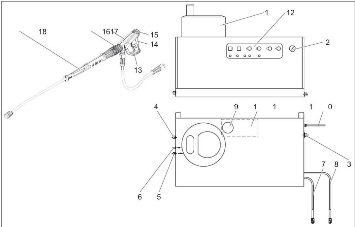
11 Float switch
12 Service area
13 Fuel tank
14 Drain plug
15 Safety lock of the pressure washer
16 Pressure washer EASY!Force
17 Adjustment of pressure/quantity of the pressure washer
18 Trigger for spraying EASY!Lock
Service area
Figure 2 A Device switch B Thermoregulator C Spray nozzle for detergent I D Spray nozzle for detergent II (optional) E Control lamp for burner malfunction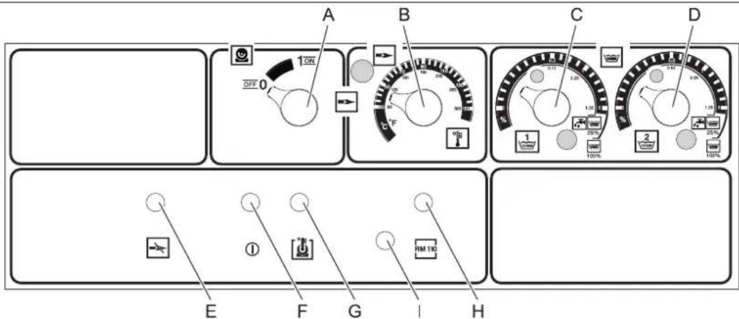
F Control lamp for readiness for operation
G Control lamp for engine stop
H Control lamp for protection against pressure build-up in the boiler
I Button for resetting the burner motor
Start-up in operation
WARNING
Danger of injury! Before use, check the accessories, protective devices, cables, and connections for proper condition. If the device is not in proper condition, its use is prohibited.
Electrical connection
- For connection parameters, see Technical Data and the type plate. - The electrical installation must be carried out by an electrician and must comply with IEC 60364-1.
Maintenance
DANGER
Danger of explosion! Do not use flammable liquids. DANGER
Danger of injury! Never use the device without the spray hose. Before each use, check the tightness of the hose connections. The tightening of the spray hose must be checked by hand.
DANGER
Danger of injury! When working, hold the spray gun with both hands and the spray hose with two hands.
DANGER! Before starting work, lower the ladder and make sure the post is not blocked.
Danger of falling! When lowering the post, keep away from the ladder.
Safety instructions
The user must use the device according to the instructions. He must comply with the safety regulations and be careful when working with the device near people.
During work, the device must not be left unattended.
- Danger of burns from hot water! The water jet must not be directed at people or animals.
- Danger of burns from hot parts of the device! When working with hot water, do not touch uninsulated pipes and hoses. Hold the pipes for spraying only by the handles. Do not touch the nozzles for discharging hot water from the device or for quickly drawing hot water.
- Danger of poisoning and irritation from cleaning agents! Follow the instructions for cleaning agents. Cleaning agents must be stored in a place inaccessible to unauthorized persons.
Danger to life from electric shock! Do not direct the water jet at electrical equipment:
electrical devices and installations, - the installation itself, - all electrical parts in the working area.
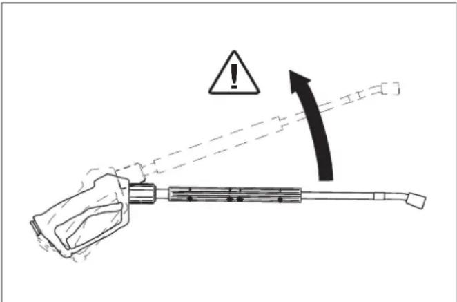
The reaction force from the spray pipe of the water jet creates a reactive force. Through the spray pipe, the force acts backwards.
DANGER
- Danger of injury! The recoil of the spray gun can knock you off balance. You can find... The spray gun can jump and injure someone. Ensure a secure position and hold the gun firmly. Do not point the gun at yourself or others to clean objects or clothing. Danger of injury from rotating parts. Loose clothing or objects can injure people or animals. Never point the water gun at people or animals.
- Danger of injury from electric shock! Keep the mains plug and extension cable at a distance of at least 30 cm.
DANGER
Danger of health damage from harmful substances! Do not inhale the following materials, as they may contain substances harmful to health:
Asbestos-containing materials, - Materials that may contain substances harmful to health.
DANGER
- Danger of injury from high-pressure water jet! Only original Karcher nozzles for working under high pressure are optimally suited for cleaning. When using other nozzles, no guarantee is given.
- Health hazard from cleaning agents! When cleaning agents are used, the water discharged from the nozzle does not meet the quality of drinking water.
- Danger of eye injury when working near the nozzle and water jet! In such cases, wear eye protection.
Opening/Closing the spray gun for high-pressure cleaning
→ Opening the spray gun for high-pressure cleaning: Press the trigger guard down. → Closing the spray gun for high-pressure cleaning: Release the trigger guard.
Changing the nozzle
DANGER
Danger of injury! When changing nozzles, only use the spray gun for high-pressure cleaning when the device is without pressure.
→ Set the nozzle for the desired pressure, as for spraying, before using the sprayer. → Change the position.
Preparing for operation
DANGER
Danger of injury from rotating fan blades!
DANGER
Before starting operation, check the nozzle for working under pressure for damage. Replace damaged nozzles immediately.
→ Nozzles for work must be checked for damage before use, as well as hoses, fittings, and pipes for spraying. → The nozzle tip must be checked for secure attachment and tightness.
CAUTION
Danger of damage due to dry running.
→ Check the level of the rinsing liquid in the reservoir for the chemical preparation when needed. → Check the level of the softening liquid and add more if necessary.
Switching off the device
Turn the pressure switch (A) to "0". Close the water inlet. Activate the spray gun until the device is without pressure.
Adjusting the working pressure and the amount of supply
Adjusting the pressure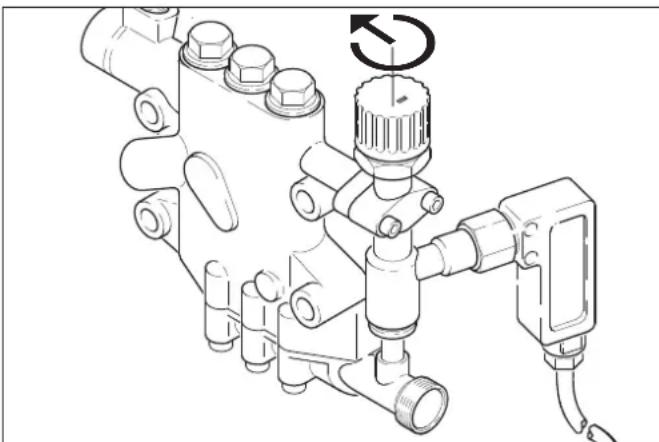
By turning the valve for adjusting the amount in the direction of the clockwise arrow, a higher working pressure and a larger amount of supply are obtained. By turning the valve for adjusting the amount in the direction opposite to the clockwise arrow, a lower working pressure and a smaller amount of supply are obtained.
The regulator is adjusted to the pressure/quantity of water for the rinse (optional)
DANGER
Danger of burns! When adjusting the pressure/quantity, be careful not to splash.
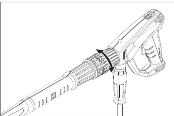
Turn the water quantity regulator fully clockwise for low operating pressure. Turn the water quantity regulator fully counterclockwise for high operating pressure.
Rinse mode
→ Open the water inlet.

Symbol "Rinse on"
Release the rinse trigger by pulling it back and removing the trigger guard. Open the rinse nozzle and place the trigger in the (A) position (including motor). → The ready-for-operation control lamp (F) indicates readiness for operation.
Burner mode
△DANGER
Danger of scalding!
CAUTION
Burner mode without burner water until the burner is activated. Before burner mode with burner water, ensure the burner is activated. If necessary, the burner can be switched on additionally.

Symbol "Burner on"
→ Place the trigger in the (A) position of "Burner on". Set the desired water temperature with the temperature regulator (TB). The maximum temperature is 98 °C
DANGER! Risk of explosion! When working at temperatures above 98 °C, the working pressure must not exceed 3.2 MPa (32 bar).
To switch from burner operation to steam operation, the device must be left to cool down and then switched off. The switch is carried out as follows:
→ Close the high-pressure pump valve (accessory).
| № 3a посыка Тип | |
| 4.116-000 HDS 9/14 | |
| 4.116-001 HDS 12/14 |
Set the thermostat to 150 °C.
Without adjusting the pressure/quantity of the nozzle for direct spraying
Set the valve for adjusting the amount of high-pressure pump water to the minimum amount of water (turn it counterclockwise).
With adjustment of the pressure/quantity of the nozzle for direct spraying (optional)
→ Set the valve for adjusting the amount of high-pressure pump water to the maximum amount of water (turn it clockwise). Set the regulator for the amount of water at the nozzle for direct spraying to the minimum amount of water by turning it to the left.
READY FOR OPERATION
-If during operation the nozzle for direct spraying is closed, the device switches off. -When the nozzle is opened again, the device automatically returns to the set readiness time for operation (2...8 minutes). -If the readiness time for operation is exceeded, the safety shutdown occurs during shutdown of the pump and the burner. The control lamp for readiness for operation (F) goes out. -For a restart in operation, set the switch on the device to "0", then switch it on again. If the device is controlled by remote control, the restart in operation can be triggered by the corresponding switch on the remote control.
NOZZLE SELECTION
-Rubber hoses must only be cleaned with a flat spray nozzle (25°) and a minimum distance of 30 cm from the spray. Rubber hoses must never be cleaned with a rotary spray.
For all applications, you can choose from the following nozzles:
| Замberя- ване | Дюза bгы | н На Вирьск- ване | Част № Нa | Яга- нe [MPa] | Peakтinue- на сида [N] |
| HDS 9/14 | |||||
| силино 000 | 60 0° 5.76 | 65-240 14 44 | |||
| средно | 25060 25° | 5.7 | 65-027 | ||
| лесо | 40060 40° | 5.1 | 30-087 | ||
| HDS 12/14 | |||||
| силино 000 | 80 0° 5.76 | 65-243 14 5 | |||
| средно | 25080 25° | 5.7 | 65-061 | ||
| лесо | 40080 40° | 5.7 | 65-221 | ||
Pipe connection of 20 m to the pipe for supply of 2 x 10 m marked for high pressure can be used for the following doses:
| Замberгованe | Дюзabгын haВирьск-ванe | Част № Ha | Яга-he [MPa] | Peaktnib- ha сида [N] |
| HDS 9/14 | ||||
| сinлно 007 | 5 0° 5.765-242 | 10 37 | ||
| срдно | 2575 | 25° | 5.765-057 | |
| пеко | 4075 | 40° | 5.765-220 | |
Dosing of cleaning agent
- Cleaning agents are sprayed for the cleaning task. They are sucked from the higher reservoir for cleaning agents. - The main equipment is equipped with dosing valves (C). As a special accessory, dosing devices (dosing valves) can be purchased. Then there is the possibility to suck in different cleaning agents. - The quantity of dosing is adjusted by the dosing valves for cleaning agent (C with D) on the service unit. The set value corresponds to the amount of cleaning agent.
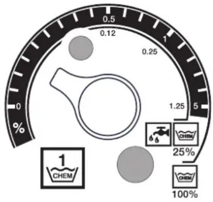
- The upper scale is valid when using undiluted cleaning agent (100% CHEM). - The lower scale is valid when using pre-diluted 1+3 cleaning agent (25% CHEM + 75% BDA).
The following table shows the consumption of cleaning agent for the values of the upper scale:
| HDS 9/14 | |||
| Stellung | 0,5 | 1 | 5 |
| Колиесто поочистваши пpenapat [н/ч] | 14...15 2 | 2...24 50 | |
| Концентраит поочистваши пpenapat [%] | 1,5 | 2,5 | 5 |
| HDS 12/14 | |||
| Stellung | 0,5 | 1 | 5 |
| Колиесто поочистваши пpenapat [н/ч] | 10...13 2 | 3...27 60 | |
| Концентраит поочистваши пpenapat [%] | 1 | 2 | 5 |
The exact quantity of dosing depends on: - Viscosity of the cleaning agent - Suction height - The resistance of the pipe under high pressure
If precise dosing is required, the quantity of suctioned cleaning agent must be measured (e.g., by suctioning from a measuring container).
Note: Recommendations for cleaning agents are given in the chapter "Accessories".
Wear protective clothing
CAUTION
During operation without protective clothing, due to the rapid evaporation of water, limescale can form. When using the reservoir for protective clothing, the control lamp for protection against limescale formation (H) lights up.
Figure 1-pos.9
→ Fill the reservoir for protective clothing RM 110 (2.780-001) with protective clothing liquid.
Stopping operation
DANGER
Danger of burns from hot water! Always check the water temperature before use. The device is designed to work with cold water only. Do not expect it to heat water within minutes.
Working with the device
→ Set the thermostat (B) to the lowest temperature when using hot water. → Use the device for 30 seconds without detergent.
Switching off the device
Turn the device switch (A) to "0". → Close the water inlet. Activate the spray gun for rinsing until the device is without pressure. Ensure the spray gun for rinsing is equipped with the designated spray lance against stubborn dirt.
Shutting down
If the device is not in use and storage is not possible, protect it against freezing. Take the necessary measures (see chapter "Maintenance and Care", section "Protection against freezing"):
→ Drain the water. → The device must be filled with antifreeze. → Switch off the device and disconnect it from the power supply.
Storage
DANGER
Danger of injury and burns! When storing, always keep the device out of reach of children.
Transport
CAUTION
When transporting, always place the device on the drain hose.
DANGER
Warning: Improper use and installation! When transporting the device, keep it in an upright position.
→ Transporting the device in a vehicle must be done in accordance with the regulations for prevention of accidents and fire.
Technical data
Possible smoke on the flue gas outlet pipe when operating with natural gas
Flue gas pipe
-The flue gas pipe must be connected to its own pipe. -The flue gas pipe must be installed in accordance with local regulations and coordinated with the chimney sweep.
Recommended installation of the flue gas pipe between the device and its own pipe.
Note: To achieve the specified emission values, the flue gas pipe must be installed according to the technical data.
Wall installation
-Before installation, check the load-bearing capacity of the wall. The supplied mounting materials are suitable for concrete. For walls made of hollow bricks, aerated concrete, or gas concrete, suitable anchors or bolts must be used, e.g., injection anchors (drilling template is included in the packaging). -Figure 3, pos. 19 and 23
The device must not be connected directly to the water supply or heating system under high pressure. The marked connections must be installed immediately.
-Figure 3-A
Between the water supply network and the connection marked, a shut-off valve must be installed.
Installation of the flue gas pipe under high pressure
The installation of the flue gas pipe under high pressure must comply with the relevant national regulations of the legislation.
- The piping must be designed for a pressure of 1.5 MPa. The piping must be tested at 2.8 MPa. The insulation of the piping must be installed for temperatures up to 155 °C.
Arrangement of the reservoirs for cleaning agents
Figure 3 - item 20
The reservoirs must be arranged so that the lowest level of the cleaning agent is not lower than 1.5 m below the bottom of the device, and the highest level is not higher than the bottom of the device.
Water connection
Figure 3 - item 19
Connect the water inlet with a suitable water connection to the water supply network. The water connection must have a minimum flow rate of 1300 l/min at a minimum pressure of 0.1 MPa. The water temperature must be below 30 °C.
Electrical connection
WARNING
Do not exceed the maximum permissible mains voltage for the connection (see technical data). If the voltage of your mains supply does not comply with the specifications, the mains voltage may be too high for your electrical installation.
Note: The connection process may cause brief voltage drops. Under unfavorable conditions, these may have adverse effects on other devices.
For connection parameters, see technical data and the type plate. The electrical installation must be carried out by an electrician and must comply with IEC 60364-1. The electrical parts, cables, and devices within the working range must be in perfect condition and protected from water splashes.
DANGER
To avoid electric shock, we recommend using a residual current device (RCD) with a rated tripping current of no more than 30 mA.
Permanent electrical installation
→ Install the electrical connection.
For starting the stationary unit for pumping under high pressure, it is necessary to install the shut-off valve (Fig. 3 - Pos. 6) on the supply line, which is not dangerous when open.
The width of the shut-off valve must be at least 3 mm.
Electrical connection with wrench/contact
→ Mount the wrench on the connection cable of the unit. → Place the wrench in the contact. For switching off the stationary unit for pumping under high pressure, the wrench must be in an easily accessible place for disconnecting the mains.
First start-up
→ Before first use, fill the oil reservoir of the water pump.
Measures before start-up
DANGER
Danger of explosion! Use only diesel fuel or heating oil. The use of other fuels, e.g., gasoline, is prohibited. → Fill the fuel reservoir.
CAUTION
Running with water without fuel until the fuel pump is stopped. Before running with fuel, ensure that the fuel is filled.
Figure 3 - Pos. 14 Note: The EASY!Lock system connects components by means of a high-efficiency thread with only one turn - quickly and safely. → Screw the high-pressure connection with a wrench for even tightening and then screw it to the high-pressure outlet of the unit and to the high-pressure hose.
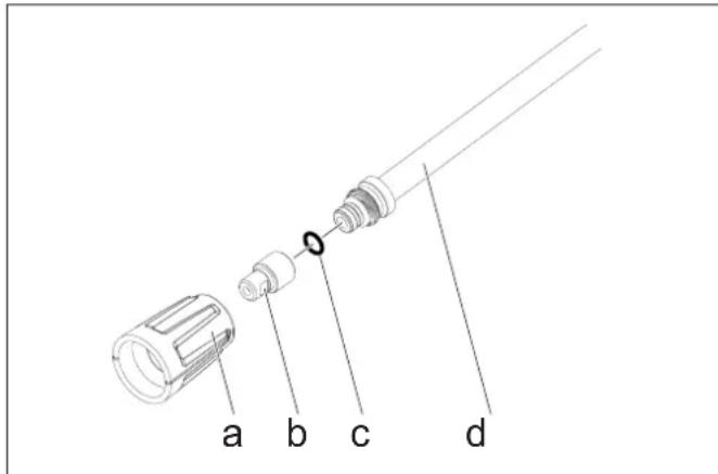
Secure the nozzle (b) with the union nut (a) on the spray lance (d). Make sure that the sealing ring (c) fits exactly in the groove.
Protection against vapor formation
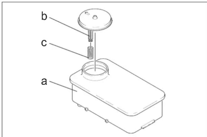
Pull the trigger (c) away from the bracket (b) on the unit with the nozzles (a). → Fill the unit with the nozzle set from Karcher RM 110 (order no. for the brush).
DANGER
Danger due to electrical voltage! The device may only be set up by an electrician.
→ To set the water hardness: - from the local water supply company, - with the hardness test kit (order no. 6.768-004). → The water connection is open. Open the main tap on the dosing panel.
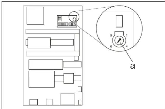
Set the potentiometer (a) according to the water hardness. The correct setting can be found in the table.
Example:
Set for water hardness of 15°dH, scale value 6 on the potentiometer. This results in a pause time of 31 seconds, i.e. every 31 seconds the dosing valve opens briefly.
| Тьрдост ha bo'daça (°dH) | 5 | 10 | 15 | 20 | 25 | |||
| Скала ha повсиометьр bьртөне | 8 | 7 | 6 | 5 | 4 | |||
| Вөрeme ha пayза (секунд) | 50 | 40 | 31 | 22 | 16 | |||
Adjusting the time until ready for operation
The adjustment of the time until ready for operation is carried out on the rear panel of the control cabinet.
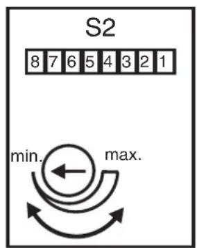
The time until ready for operation is set at the factory to a minimum time of 2 minutes and can be increased to a maximum time of 8 minutes.
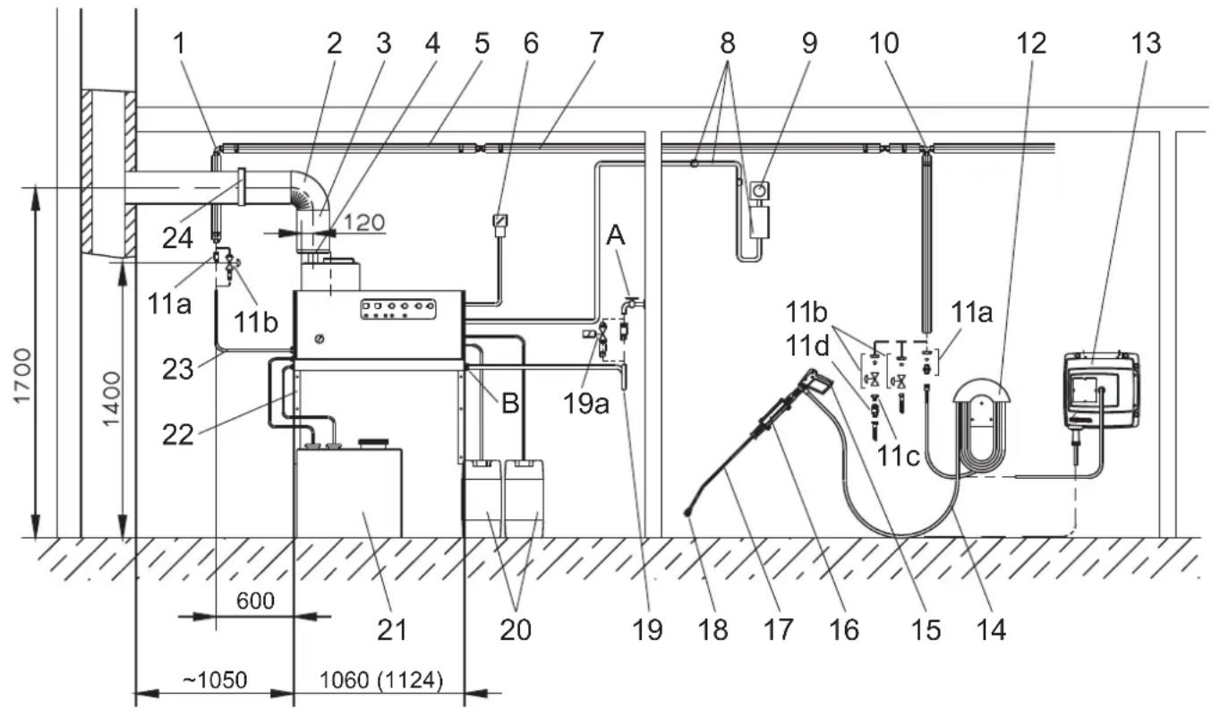
Figure 3
| Поз.И | Нстацноен Матерnam № 3а поч- | ka |
| 1 Тгл� | Во peзбовс bединени 6.386-356 | |
| 2 Огьн | Са ча на трьба 3a димни raзовe 90° | 7.234-605 |
| Огьна та ча на трьба 3a димни raзовe 45° | 7.234-604 | |
| 3 Трьб | За димни raзовe 7.234-603 | |
| 4 Ппек | Сван ha тяга трьба 3a димни raзовe HDS 9/14-4 | 4.656-080 |
| Ппекsbvaи ha тяга трьба 3a димни raзовe HDS 12/14-4 | 4.656-079 | |
| 5 Толлотация 6.286-114 | ||
| 6 Гавенпөрьсвач 6.631-455 | ||
| 7 Komп | Трьборови, рочинкован CTOMанa | 2.420-004 |
| Компөрт трьборови, бларорodia CTOMaHa | 2.420-006 | |
| 8 Komп | Тр actи достанцioнho уразалne- Hne | 2.744-008 |
| 9 Komп | Тр actи пөрьсвач abarийho ИЗ- Kлочваe | 2.744-002 |
| 10 T-ошрaso reбовс bединени 6.386-269 | ||
| 11a Ппсьденителен уцер, месинr 2.638-180 | ||
| Ппсьденителен уцер, bларорodia CTOMaHa | 2.638-181 | |
| 11b Спрателен кран NW 8, рочинкован CTOMaHa | 4.580-144 | |
| Спрателен кран NW 8, bларорodia StO-maHa | 4.580-163 | |
| 11c Heпдвжна част за bьрzo рпсьдени- BAhe | 6.463-025 | |
| 11d Ппдвжна част за bьрzo рпсьдениява- He | 6.463-023 |
| Поз.И | Нстацноен Матерnam № за порь- | ka |
| 12 Hocан 3a Маркуа | 2.04 | 2-001 |
| 13 Баран на маркуа | 2.63 | 7-238 |
| 14 Маркуза Виско налаягане EASY!Lock 10 m (Врьзки 2x TR) | 6.110-038 * | |
| 15 Пистолетота рычно пьскане EASY!Force | 4.118-005 | |
| Вьртуш р发电机хт HDS 9/14-4 | 4.118-008 | |
| Вьртуш р发电机хт HDS 12/14-4 4.118-009 | ||
| 16 Нocан на разимпьсваша травба | 2.04 | 2-002 |
| 17 Трьза 3a разимпьсваше EASY!Lock | 4.11 | 12-012 |
| 18 Мундшик на дюзата HDS 9/14-4 | 2.11 | 13-026 |
| Мундшик на дюзата HDS 12/14-4 | 2.113-015 | |
| 19 Маркуза ВODа | 4.44 | 40-282 |
| 19a Магнистен вентли поадане на ВODа | 4.743-011 | |
| 20 Розерbooар за поочствац пpenapat, 60 п 5.070-078 | 6.39 | |
| 21 Розерbooар за мазут 600 п | 6.39 | 2-050 |
| 22 Komплесктусти Stěнна колона | 2.05 | 3-005 |
| Комплесктусти Stěнна Stôйка | 2.210-008 | |
| 23 Маркуза Виско налаягане EASY!Lock 1,5 m (Врьзки TR - M22x1,5) | 6.110-068 | |
| Mapkyза Виско налаягане EASY!Lock 1,5 m (Врьзки 2x TR) | 6.110-024 * | |
| 24 Стоа за пьби | 6.37 | 3-374 |
- An adapter is required - M22x1.5 (4.111-030)
EC Declaration of Conformity
With this declaration, we confirm that the machine described below complies with the relevant basic safety and health requirements of the EC directives in its design and construction, as well as in the version we put into circulation. This declaration becomes invalid if the machine is modified without our consent.
Product: High-pressure cleaning unit with accessories
Tun: 1.698-xxx
Tun: 1.699-xxx
Directive applicable de l'UE:
2014/68/EC
2006/42/EC (+2009/127/EC)
2014/30/EC
Catégorie/Module
II
Procédure de conformité
Module
Segment de chauffage
Évaluation de conformité Module H
Différents tuyaux
Évaluation de conformité Art. 4(3)
Normes harmonisées applicables:
EN 55014-1:2006+A1:2009+A2:2011
EN 55014-2: 2015
EN 60335-1
EN 60335-2-79
EN 61000-3-2: 2014
HDS 12/14:
EN 61000-3-3:2013
HDS 9/14:
EN 61000-3-11:2000
Specifications subject to change without notice.
Based on AD 2000
Chairman of the Board of Management
Director Regulatory Affairs & Certification
71364 Winnenden (Germany)
Tel.: +49 7195 14-0
Fax: +49 7195 14-2212
Winnenden, 2018/10/01
Warranty
The warranty conditions published by our authorized distributor apply. Any damage to your device will be repaired free of charge under warranty, if it is due to a defect in materials or manufacturing. For warranty service, contact the distributor or the nearest authorized service center, presenting the cash receipt.
Customer service
Date of manufacture: Commissioning date:
Inspection carried out:
Conclusion:
Signature
Inspection carried out:
Conclusion:
Signature
Inspection carried out on:
Conclusion:
Signature
The check was carried out on:
Conclusion:
Signature
Note: The inspection intervals must be observed in accordance with the relevant national requirements in the country of the consumer.
Repeat inspections
| Поверкatinga поveда на ot: Вьнucha поveberka Bьтreceна поveberka Поверка на здравината | ||
| Иme Повпис на правocnocobno- | TO liuce/Data | Повпис на правocnocobno-TO liuce/Data |
| Иme Повпис на правocnocobno- | TO liuce/Data | Повпис на правocnocobno-TO liuce/Data |
| Иme Повпис на правocnocobno- | TO liuce/Data | Повпис на правocnocobno-TO liuce/Data |
| Иme Повпис на правocnocobno- | ||
| Иme Повпис на правocnocobno- | TO liuce/Data | Повпис на правocnocobno-TO liuce/Data |
| Иme Повпис на правocnocobno- | TO liuce/Data | Повпис на правocnocobno-TO liuce/Data |
| Иme Повпис на правocnocobn- | ||
| Иme Повпис на правocnocobno- | TO liuce/Data | Повпис на правocnocobno-TO liuce/Data |
| Иme Повпис на правocnocobno- | TO liuce/Data | Повпис на правocnocobno-TO liuce/Data |
| Иme Повпис на правocnocibn- | ||
| Иme Повпис на правocnocobn- | TO liuce/Data | Повпис на правocnocobn-TO liuce/Data |
| Иme Повпис на правocnocobn- | TO liuce/Data | Повпис на правocnocobn-TO liuce/Data |
| Иme Повпис на правocnocobn- | TO liuce/Data | Повпис на правocnocobn-TO liuce/Data |
| Иme Повпис на правocnocobn- | ||
| Иme Повпис на правocnocobn- | TO liuce/Data | Повпис на правocnocobn-TO liuce/Data |
| Иme Повпис на правocnocobn- | TO liuce/Data | Повпис на правocnocobn-TO liuce/Data |
| Иme Повпис на правoc nocobn- | ||
| Иme Повпис на правocnocobn- | TO liuce/Data | Повпис на правocnocobn-TO liuce/Data |
| Иme Повпис на правocnocobn- | TO liuce/Data | Повпис на правocnocobn-TO liuce/Data |
| Иme Повпис на правOCNOCBO- | ||
| Иme Повпис на правOCNOCBO- | TO liuce/Data | Повпис на правOCNOCBO-TO liuce/Data |
| Иme Повпис на правOCNOCBO- | TO liuce/Data | Повпис на правOCNOCBO-TO liuce/Data |
| Иme Повпис на правOCNOCBO- | TO liuce/Data | Повпис на правOCNOCBO-TO liuce/Data |
| Иme Повпис на правOCNOCBO- | ||
| Иme Повпис на правOCNOCBO- | TO liuce/Data | Повпис на правOCNOCBO-TO liuce/Data |
| Иme Повпис на правOCNOCBO- | TO liuce/Data | Повпис на правOCNocbo-TO liuce/Data |

www.kaercher.com/REACH
Indicates an imminent threat of danger that may result in serious injury or death.
WARNING
Indicates a potentially dangerous situation that may result in serious injury or death.
CAUTION
Product: Steam pressure washer
Type: 1.698-xxx
Type: 1.699-xxx
A. Schenner
Chairman of the Board of Management
S. Reiser Director Regulatory Affairs & Certification
71364 Winnenden (Germany)
Tel.: +49 7195 14-0
Fax: +49 7195 14-2212
Winnenden, 2018/10/01
Warranty
www.kaercher.com/REACH
Risk of injury
△DANGER
Indicates an imminent threat of danger that will lead to serious injuries or death.
WARNING
Indicates a potentially dangerous situation that could lead to serious injuries or death.
△CAUTION
Indicates a potentially dangerous situation that may lead to minor injuries.
WARNING: Possible dangerous situation that could result in material damage.
Symbols on the device

If used incorrectly, the high-pressure jet can be dangerous. The jet must not be directed at people, animals, live electrical equipment, or the device itself.
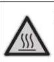
Risk of burns when working on hot surfaces!
General safety instructions
Chairman of the Board of Management
S. Reiser Director Regulatory Affairs & Certification
Authorized to prepare documentation:
S. Reiser
Alfred Karcher SE & Co. KG
71364 Winnenden (Germany)
Tel.: +49 7195 14-0
Fax: +49 7195 14-2212
Winnenden, 2018/10/01
Warranty
www.kaercher.com/REACH
Risk Levels
DANGER
Indication of an imminent danger that could lead to serious bodily injury or death.
WARNING
Indication of a possible danger that could lead to serious bodily injury or death.
CAUTION
Indicates a possible danger that could lead to minor injuries.
ATTENTION
Indication of a possible danger that could lead to material damage.
Symbols on the device

Chairman of the Board of Management
S. Reiser Director Regulatory Affairs & Certification
71364 Winnenden (Germany)
Tel.: +49 7195 14-0
Fax: +49 7195 14-2212
Winnenden, 2018/10/01
Warranty
Maintenance plan. UK 14
Declaration of Conformity for the European Community
UK 17
Warranty. UK 17
Customer Service. UK 18
Inspection intervals. 19
Environmental protection

Packaging materials are recyclable. Please do not dispose of packaging materials with household waste, but recycle them.

Old devices contain valuable materials that can be recycled. Batteries, oil, and similar materials must not enter the environment. Therefore, please dispose of old devices using appropriate collection systems.
Please do not allow oil, grease, or fuel to enter the environment. Please protect the soil and dispose of used oils properly, without harming the environment.
Kärcher cleaning agents are biodegradable (ASF). This means they will not interfere with the operation of the oil separator. A list of recommended cleaning agents is provided in the "Accessories" section.
Instructions for use of components (REACH)
Current information about components is available on the web page at:
www.kaercher.com/REACH
Safety levels
DANGER
Indicates an imminent danger that directly leads to serious injuries or death.
WARNING
Indicates a potentially dangerous situation that could lead to serious injuries or death.
CAUTION
Indicates a potentially dangerous situation that could lead to minor injuries.
ATTENTION
Indicates a potentially dangerous situation that could lead to material damage.
Symbols on the device

The jet under high pressure can be dangerous if used incorrectly. Do not
direct the jet at people, animals, live electrical equipment, or at the device itself.
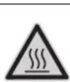
Safety instructions about the device!
General safety instructions
It is necessary to comply with the relevant national legal regulations for working with high-pressure cleaners. It is necessary to comply with the relevant national legal regulations on technical safety. It is necessary to regularly check the operation of high-pressure cleaners and record the results of the checks in writing. The device's pressure relief valve is a safety device. It is necessary to regularly check the safety devices in compliance with the relevant national legal regulations. When operating the device, it is necessary to ensure the safe removal of exhaust gases (pipe without interruption for the removal of flue gas). The data must be sufficient for the safe operation of the device. According to your national regulations, this high-pressure cleaner is intended for professional use by trained personnel. KARCHER service partners have carried out the first commissioning process and documented this process. The documentation can be obtained from the authorized KARCHER service partner. When requesting documentation, please specify the device model and serial number. We refer to the fact that, in accordance with your national regulations, the device must be regularly inspected by trained personnel. Please contact the KARCHER service partner. Follow the safety regulations for the cleaning agents used (usually indicated on the packaging). Any modifications to the device or additional equipment are prohibited.
Intended use, directives and standards
The installed device must be connected to the exhaust system with a ventilation connection.
When installing, it is necessary to comply with the applicable building regulations, labor regulations and environmental protection. We refer to the relevant regulations, directives and standards:
- In accordance with the current national regulations, only specialized equipment may be installed.
- When performing electrical work, it is necessary to comply with the relevant national standards. - Setup, operation, maintenance and repair may only be carried out by trained service technicians from Karcher. - When designing the exhaust gas pipes, it is necessary to comply with the relevant local state regulations.
Operation
The working area of the nozzle and control. Other work, depending on the design of the device, may require additional equipment (accessories) for special applications.
Personal protective equipment

When working in areas with high noise levels, it is necessary to wear appropriate hearing protection to prevent hearing damage.
Wear protective clothing and protective goggles to protect against water and dirt that may splash.
Proper use
The device is used for removing dirt from surfaces using a high-pressure water jet. In particular, it is used for machines, automobiles and building facades.
HEB63NEKA
Safety instructions! When using autonomous stations or other unsafe zones, follow the additional safety rules.
Do not allow oil to enter the ground, water, or sewage. Therefore, maintenance and repair of the machine should be carried out only in designated places with oil collection.
Water quality:
ATTENTION
Only clean water can be used for high-pressure cleaning. Contamination leads to premature wear of the device and additional equipment or sediment in them.
If you use water repeatedly, you must not exceed the specified limits of contamination.
The pressure gauge switch turns off the device when the operating pressure is exceeded. Do not change the setting.
Safety valve
When the pressure gauge switch is triggered, the safety valve opens. This valve is adjusted and sealed at the factory. Do not change the setting.
Leak control
If there is a leak or the leak control system detects a leak, the device switches off. The leak indicator lamp (E) lights up.
Overload protection
If the trigger is locked, the overload protection device switches off. The high-pressure pump is protected by the overload switch and the motor protection relay.
Thermostat for exhaust gases
The gas pressure regulator ensures that the gas pressure regulator temperature exceeds 300 °C. It is applied.
Pressure gauges in the high-pressure system
Before starting the pneumatic manual sprayer and before closing the valve for preparation for work, the magnetic valve located in the high-pressure system opens, resulting in a pressure drop.
Safety valve
The safety stop of the manual sprayer prevents accidental activation of the device.
Elements of the device
Fig. 1 1 Burner 2 Pressure gauge 3 Hose for compressed air with pressure reducer 4 High-pressure outlet EASY!Lock 5 Supply hose for spraying agent 6 Return hose for spraying agent 7 Connection for additional agent I 8 Connection for additional agent II (initial filling) 9 Valve with M' K W y a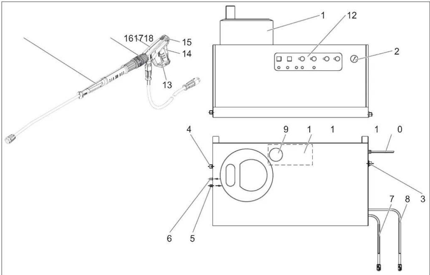
10 Electric motor
11 Float chamber
12 Control lever
13 Safety valve
14 Drain
15 Safety stop of the sprayer
16 Sprayer EASY!Force
17 Pressure/quantity adjustment on the manual sprayer
18 CtpymnHa Tpy6ka EASY!Lock
PahenbynpaBnHH
Man. 2 A Anapathm BIMMkau B PernyarTop Tempepatypn C Do3yUOCh KlaanH MmHoro 3ac06yI D O3yUOH KnaH MnHOro 3acO6y II (doaTKOBe oBnaHaH-H)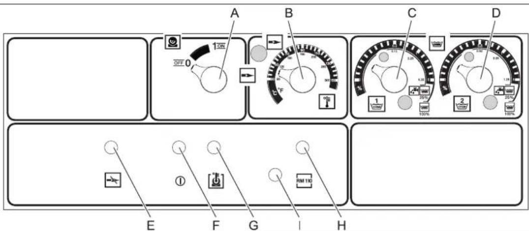
E KoHTpOlbHa JAmNoUcKa HecnpaBHOcti NaJbHnKa
F KOthponbHa nAmna roTOBHOCTI do eKcnnyataui
G KOnTpObnHa JAmnHa neperpiBy DBrHyHa
H KohtponbHa JAmna 3axncty BiD hakiny
13aIyuka-KhONka De6NOKyBaHHa DnBryHa naIbHnka
BVeDeHnB EeknIyatauio
△NONEPEDXEHNA
Hebe3neka mpaemyeaHn! Ppucmpi, dodamkoe obnadhaHn, nii niodeedehna ma 3'cdHyaealbhi enemeHmu noeunHi sbymu y be3dozahHomy cmani. KaO cman e HecnpaBHum, mo npucmpiu bukopucmooyamu He moxHa.
PiikluoyenHa do dkepeTa ToKy
-3haeHHraoOIO nIKJIIOueHHraDVB.TexHicHi daHI ta 3aBOIDcKy Ta6nUky. - EneKtpnHi 3'edHaHnH NoBnHH6yTN BnKoHaH eNektpomOH TaHKOM Ta BiNoBjDaTu IEC 60364-1.
Eknpnyataia
HEBE3NEKA
Safety! Do not understand the road sign.
SAFETY
Safety instructions! Never use without an approved suction hose. Check the presence of the suction hose before each use. The hose must be firmly connected to the suction hose connection.
SAFETY
Safety instructions! During work, keep the nozzle and suction hose away from your hands.
SAFETY
Safety instructions! When using the drain and fill valves, they must not be blocked.
SAFETY
Safety instructions! In case of damage to the fill valve, contact the service center.
Safety rules
The user must use the device in accordance with the instructions. They must take into account the local conditions and pay attention to third parties during work with the device.
Do not leave the device without supervision.
SAFETY
Safety instructions for electrical connection! Do not point the hose at people or animals. - Safety instructions for electrical installation! When working with electrical connection, do not touch the power cord and hose. The suction hose should only be held by the handle. Do not touch the switch with wet hands. Safety instructions for poisoning or chemical burns! Use the cleaning agent only as directed. Store the cleaning agent in a place inaccessible to unauthorized persons.
SAFETY
DANGER! Electric shock hazard! Do not direct the water jet at the device:
- electrical devices and installations, on parts of this installation,
- all parts that conduct current in the working area.
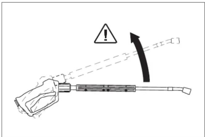
Through the water jet, which exits from the spray gun, a reaction force is generated. Through the spray gun, which is held, the force acts downward.
DANGER
Danger of injury! The force of the spray gun can cause injury to your hand. You can injure yourself. The spray gun can slip and injure you or others. Choose a stable working position and hold the spray gun firmly. Do not point the spray gun at yourself or at other people or animals. - Danger of injury from parts that are ejected! Ejected parts or objects can injure people or animals. Do not point the water jet at lamps or unprotected objects. Danger of injury from the device! Keep hands and feet away from the device at least 30 cm.
WARNING
Danger, which can cause health damage! Do not use the following materials, as they may contain substances harmful to health:
- asbestos-containing materials, materials that may contain hazardous substances for health.
DANGER
Danger of injury from the high-pressure jet, possibly hot water! Only original high-pressure hoses of Kärcher are suitable for the device. When using other hoses, the warranty is void. - Danger to health from eye contact with cleaning agents! Through additives, if necessary, cleaning agents, the water entering the device does not meet the quality of drinking water. - Danger of damage to hearing organs during work with the device, which produces loud noise! In this case, it is advisable to wear hearing protection.
Opening/closing the spray gun
Open the spray gun: Press the trigger and release the safety lock. Close the spray gun: Release the trigger and engage the safety lock.
Spray nozzle
DANGER
DANGER! Before switching on, connect the device and attach the spray gun-nozzle, until the device is completely filled with liquid.
Secure the spray gun-nozzle by tightening the rear clamp. Replace the nozzle.
Check readiness for operation
DANGER
Danger of injury from high-pressure water jet, possibly, hot water!
DANGER
Check the device for damage before use. Replace damaged parts immediately.
→ Before each use, check the high-pressure hose, pipelines, fittings, and spray lance for damage. → Check the connection points for tightness and sealing.
CAUTION
Danger of injury when working dry. → Check the amount of agent and top up if necessary. → Check the level of cleaning agent and top up if necessary.
Switching on in the standby mode
Turn the device switch to "0". Close the water tap. → Switch on the spray gun-nozzle until the device is free of pressure.
Set the working pressure and pump output
Device adjustment
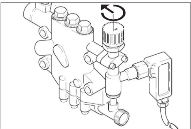
→ Turning the capacity control knob clockwise increases the working pressure and output. → Turning the capacity control knob counterclockwise reduces the working pressure and output.
Pressure regulator for spray gun on manual spray gun (option)
DANGER
Danger! During adjustment of the pressure regulator, pay attention to ensure that the screw connection of the spray gun does not loosen.
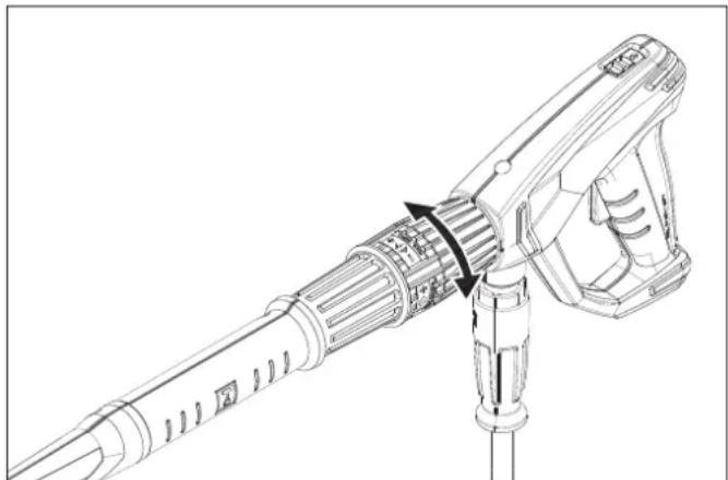
Spray gun
-Using the spray gun allows the cleaning process. The spray guns are available in different versions. -The basic version of the spray gun is equipped with a metering valve (C). The second version of the spray gun (metering valve D) can be ordered as a special accessory. This allows the use of two different spray guns. -The metering quantity is set on the control unit and the metering valve (C or D). The set value corresponds to the respective spray gun in the heights.
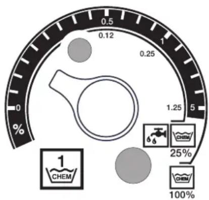
-External trigger when using undiluted spray gun (100% CHEM). -Internal trigger when using spray gun, previously diluted in ratio 1:3 (25% CHEM + 75% WATER)
The following table shows the consumption values of the spray gun in relation to the indications of the upper and lower scale.
HDS 9/14
Maintenance and servicing
DANGER
Danger! Before carrying out repair work and work on maintenance, switch off the main switch or disconnect the battery plug.
Maintenance plan
| Дата Вд дійьності війnobідіRobokіngізіRobokіngізіRobokіngізіRobokіngізіRobokіngізіRobokіngізіRobokіngізіRobokіngізіRobokіngізіRobokіngізіRobokіngізіRobokіngізіRobokіngізіRobokіngізіRobokіngізі RobokіngізіRobokіngізіRobokіngізіRobokіngізіRobokіngізіRobokіngізіRobokіngізіRobokіngізіRobokіngізіRobokіngізіRobokіngізіRobokіngізіRobokіngізіRobokіngізіRobokNY | Пушихштейпсг�оцу Чушихштейпсг�оцу Бушихштейпсг�оцу Вишихштейпсг�оцу Вишихштейпсг�оцу Бушихштейпсг�оцу Вишихштейпсг�оцу Вишихштейпсг�оцу Вишихштейпсг�оцу Вишихштейпсг�оцу Вишихштейпсг�оцу Вишихштейпсг�оцу Вишихштейпсг�o Бушихштейпсг�оцу Вишихштейпсg� Вишихштjetу Вишихштjetу Вишихштjetу Вишихштjetу Вишихштjetу Вишихштjetу Вишихштjetу Вишихштjetу Вишихштjetу Вишихштjetу Вишихштjetу Вишихштjetу | Мушиштейпсг�оцу Слійьнштейпсг�оцу Чушихштjetу Вишихштjetу Вишихштjetу Вишихштjetу Вишихшtjetу Вишихшtjetу Вишихшtjetу Вишихшtjetу Вишихшtjetу Вишихшtjetу Вишихшtjetу Вишихшtjetу Вишихшtjetу Вишихшtjetу Вишихшtjetу Вишихшt jetу Вишихшtjetу Вишихшtjetу Вишихшtjetу Вишихшtjetу Вишихшtjetу Вишихшtjetу Вишихшtjetу Вишихшtjetу Вишихшtjetу Вишихшtjetу Вишихшtjet耗 Вишихшtjet耗 Вишихшtjet耗 Вишихшtjet耗 Вишихшtjet耗 Вишихшtjet耗 Вишихшtjet耗 Вишихшtjet耗 Вишихшtjet耗 Вишихшtjet耗 Вишихшtjet耗 Вишихшtjet耗 | Корістувач |
| Пушихштjetу Слійьнштjetу Слійьнштjetу Слійьншtjetу Слійьншtjetу Слійьншtjetу Слійьншtjetу Слійьншtjetу Слійьншtjetу Слійьншtjetу Слійьншtjetу Слійьншtjet耗 Слійьншtjet耗 Слійьншtjet耗 Слійьншtjet耗 Слійьншtjet耗 Слійьншtjet耗 Слійьншtjet耗 Слійьншtjet耗 Слійьншtjet耗 Слійьншtjet耗 | Корістувач | ||
| Пушихштjetу Слійьнштjetу Слійьншtjetу Слійьншtjetу Слійьншtjetу Слійьншtjetу Слійьншtjetу Слійьншtjetу Слійьншtjetу Слійьнshtjet耗 Слійьнshtjet耗 Слійьнshtjet耗 Слійьнshtjet耗 Слійьнshtjet耗 Слійьнshtjet耗 Слійьнshtjet耗 Слійьнshtjet耗 Слійьнshtjet耗 Слійьнshtjet耗 | Корістувач | ||
| Пушихштjetу Слійьншtjetу Слійьншtjetу Слійьншtjetу Слійьншtjetу Слійьншtjetу Слійьншtjetу Слійьншtjetу Слійьншtjetу Слійьнshtjet耗 Слійьнsht jet Слійьнshtjet耗 Слійьнshtjet耗 Слійьнshtjet耗 Слійьнshtjet耗 Слійьнshtjet耗 Слійьнshtjet耗 Слійьнshtjet耗 Слійьнshtjet耗 Слійьнshtjet耗 | |||
| Пушихштjetу Слійьншtjetу Слійьншtjetу Слійьншtjetу Слійьншtjetу Слійьншtjetу Слійьншtjetу Слійьншtjetу Слійьншtjetу | Корістувач | ||
| Пушихштjetу Слійьншtjetу Слійьншtjetу Слійьншtjetу Слійьншtjetу Слійьншtjetу Слійьншtjetу Слійьншtjetу Сл嘧у Сл嘧у Сл嘧у Сл嘧у Сл嘧у Сл嘧у Сл嘧у Cл嘧у Cл嘧у Cл嘧у Cл嘧у Cл嘧у Cл嘧у Cл嘧у Cл嘧у Cл嘧у Cл嘧у Cл嘧у Cл嘧у Cл嘧у Cл嘧у Cл嘧у Cл嘧у Cл嘧у Cл嘧у Cл嘧у Cл嘧у Bicety Bicety Bicety Bicety Bicety Bicety Bicety Bicety Bicety Bicety Bicety Bicety Bicety Bicety Bicety Bicety Bicety Bicety Bicety Bicety Bicety Bicety Bicety Bicety Bicety Bicity Bicity Bicity Bicity Bicity Bicity Bicity Bicity Bicity Bicity Bicity Bicity Bicity Bicity Bicity Bicity Bicity Bicity Bicity Bicity Bicity Bicity Bicity Bicity Bicity BicITY BicITY BicITY BicITY BicITY BicITY BicITY BicITY BicITY BicITY BicITY BicITY BicITY BicITY BicITY BicITY BicITY BicITY BicITY BicITY BicITY BicITY BicITY BicITY BicITY Bicity BicITY BicITY BicITY BicITY BicITY BicITY BicITY BicITY BicITY BicITY BicITY BicITY BicITY BicITY BicITY BicITY BicITY BicITY BicITY BicITY BicITY BicITY BicITY Bicity Bicity Bicity Bicity Bicity Bicity Bicity Bicity Bicity Bicity Bicity Bicity Bicity Bicity Bicity Bicity Bicity Bicity Bicity Bicity Bicity Bicity Bicity Bicity Biccity Biccity Biccity Biccity Biccity Biccity Biccity Biccity Biccity Biccity Biccity Biccity Biccity Biccity Biccity Biccity Biccity Biccity Biccity Biccity Biccity Biccity Biccity Biccity Biccity Bic city Biccity Biccity Biccity Biccity Biccity Biccity Biccity Biccity Biccity Biccity Biccity Biccity Biccity Biccity Biccity Biccity Biccity Biccity Biccity Biccity Biccity Biccity Biccity Biccity Bicity Biccity Biccity Biccity Biccity Biccity Biccity Biccity Biccity Biccity Biccity Biccity Biccity Biccity Biccity Biccity Biccity Biccity Biccity Biccity Biccity Biccity Biccity Biccity Bic city Bic city Bic city Bic city Bic city Bic city Bic city Bic city Bic city Bic city Bic city Bic city Bic city Bic city Bic city Bic city Bic city Bic city Bic city Bic city Bic city Bic city Bic city Bic city Bic city Biccity Biccity Biccity Biccity Biccity Biccity Biccity Biccity Biccity Biccity Biccity Biccity Biccity Biccity Biccity Biccity Biccity Biccity Biccity Biccity Biccity Biccity Biccity Bic city BicCity BicCity BicCity BicCity BicCity BicCity BicCity BicCity BicCity BicCity BicCity BicCity BicCity BicCity BicCity BicCity BicCity BicCity BicCity BicCity BicCity BicCity BicCity BicCity BicCity Biccity Biccity Biccity Biccity Biccity Biccity Biccity Biccity Biccity Biccity Biccity Biccity Biccity Biccity Biccity Biccity Biccity Biccity Biccity Biccity Biccity Biccity Biccity Biccity BicCity BicCity BicCity BicCity BicCity BicCity BicCity BicCity BicCity BicCity BicCity BicCity BicCity BicCity BicCity BicCity BicCity BicCity BicCity BicCity BicCity BicCity BicCity BicCity Bic City BicCity BicCity BicCity BicCity BicCity BicCity BicCity BicCity BicCity BicCity BicCity BicCity BicCity BicCity BicCity BicCity BicCity BicCity BicCity BicCity BicCity BicCity BicCity BicCity Bic city BicCity BicCity BicCity BicCity BicCity BicCity BicCity BicCity BicCity BicCity BicCity BicCity BicCity BicCity BicCity BicCity BicCity BicCity BicCity BicCity BicCity BicCity BicCity Biccity BicCity BicCity BicCity BicCity BicCity BicCity BicCity BicCity BicCity BicCity BicCity BicCity BicCity BicCity BicCity BicCity BicCity BicCity BicCity BicCity BicCity BicCity BicCity Biccity Bic city BicCity BicCity BicCity BicCity BicCity BicCity BicCity BicCity BicCity BicCity BicCity BicCity BicCity BicCity BicCity BicCity BicCity BicCity BicCity BicCity BicCity BicCity Biccity BicCity Biccity BicCity BicCity BicCity BicCity BicCity BicCity BicCity BicCity BicCity BicCity BicCity BicCity BicCity BicCity BicCity BicCity BicCity BicCity BicCity BicCity BicCity BicCity Biccity BicCity Bic city BicCity BicCity BicCity BicCity BicCity BicCity BicCity BicCity BicCity BicCity BicCity BicCity BicCity BicCity BicCity BicCity BicCity BicCity BicCity BicCity BicCity BicCity Biccity Biccity BicCity BicCity BicCity BicCity BicCity BicCity BicCity BicCity BicCity BicCity BicCity BicCity BicCity BicCity BicCity BicCity BicCity BicCity BicCity BicCity BicCity BicCity Biccity Biccity Bic city BicCity BicCity BicCity BicCity BicCity BicCity BicCity BicCity BicCity BicCity BicCity BicCity BicCity BicCity BicCity BicCity BicCity BicCity BicCity BicCity BicCity Biccity BicCity BicCity Biccity BicCity BicCity BicCity BicCity BicCity BicCity BicCity BicCity BicCity BicCity BicCity BicCity BicCity BicCity BicCity BicCity BicCity BicCity BicCity BicCity BicCity Biccity BicCity BicCity Bic city BicCity BicCity BicCity BicCity BicCity BicCity BicCity BicCity BicCity BicCity BicCity BicCity BicCity BicCity BicCity BicCity BicCity BicCity BicCity BicCity BicCity Biccity BicCity Biccity Biccity BicCity BicCity BicCity BicCity BicCity BicCity BicCity BicCity BicCity BicCity BicCity BicCity BicCity BicCity BicCity BicCity BicCity BicCity BicCity BicCity BicCity Biccity BicCity Biccity Bic city BicCity BicCity BicCity BicCity BicCity BicCity BicCity BicCity BicCity BicCity BicCity BicCity BicCity BicCity BicCity BicCity BicCity BicCity BicCity BicCity BicCity Biccity Biccity BicCity Biccity BicCity BicCity BicCity BicCity BicCity BicCity BicCity BicCity BicCity BicCity BicCity BicCity BicCity BicCity BicCity BicCity BicCity BicCity BicCity BicCity BicCity Biccity Biccity BicCity Bic city BicCity BicCity BicCity BicCity BicCity BicCity BicCity BicCity BicCity BicCity BicCity BicCity BicCity BicCity BicCity BicCity BicCity BicCity BicCity BicCity BicCity Biccity Biccity Biccity BicCity BicCity BicCity BicCity BicCity BicCity BicCity BicCity BicCity BicCity BicCity BicCity BicCity BicCity BicCity BicCity BicCity BicCity BicCity BicCity BicCity Biccity Biccity Biccity Bic city BicCity BicCity BicCity BicCity BicCity BicCity BicCity BicCity BicCity BicCity BicCity BicCity BicCity BicCity BicCity BicCity BicCity BicCity BicCity BicCity Biccity Biccity Biccity Biccity BicCity BicCity BicCity BicCity BicCity BicCity BicCity BicCity BicCity BicCity BicCity BicCity BicCity BicCity BicCity BicCity BicCity BicCity BicCity BicCity Biccity Biccity Biccity Biccity Bic city BicCity BicCity BicCity BicCity BicCity BicCity BicCity BicCity BicCity BicCity BicCity BicCity BicCity BicCity BicCity BicCity BicCity BicCity BicCity Biccity Biccity Biccity Biccity Biccity BicCity BicCity BicCity BicCity BicCity BicCity BicCity BicCity BicCity BicCity BicCity BicCity BicCity BicCity BicCity BicCity BicCity BicCity BicCity Biccity Biccity Biccity Biccity Biccity Bic city BicCity BicCity BicCity BicCity BicCity BicCity BicCity BicCity BicCity BicCity BicCity BicCity BicCity BicCity BicCity BicCity BicCity BicCity Biccity Biccity Biccity Biccity Biccity Biccity Bic city BicCity BicCity BicCity BicCity BicCity BicCity BicCity BicCity BicCity BicCity BicCity BicCity BicCity BicCity BicCity BicCity BicCity Biccity Biccity Biccity Biccity Biccity Biccity Biccity Bic city Bic city Bic city Bic city Bic city Bic city Bic city Bic city Bic city Bic city Bic city Bic city Bic city Bic city Bic city Bic city Bic city Biccity Biccity Biccity Biccity Biccity Biccity Biccity Bic city Bic city Bic city Bic city Bic city Bic city Bic city Bic city Bic city Bic city Bic city Bic city Bic city Bic city Bic city Bic city Bic city Bic城市 BICZUHNO | Korntstvoe no. 10000000000000000000000000000000000000000000000000000000000000000000000000000000000000000000000000000 | Korntstvoe no. 10000000000000000000000000000000000000000000000000000000000000000000000000000000000000000 | |
| Odninnyi pehovnaya 6000000000000000000000000000000000000000000000000000000000000000000000000000000000000000000000000000 | |||
| Почины рыч- нiorskiya 60000000000000000000000000000000000000000000000000000000000000000000000000000000000000000000000000 |
Maintenance contract
A maintenance contract for the device can be concluded with the competent sales office of Kärcher.
Clean the sieve filter
__SUPPIMER__
Close the water tap. Turn the device clockwise. Remove the filter from the housing. Clean the filter parts. Reassemble in reverse order.
Filter parts in the system to prevent the absence of water
→ Remove the cover. Turn the corner piece from the locking block.
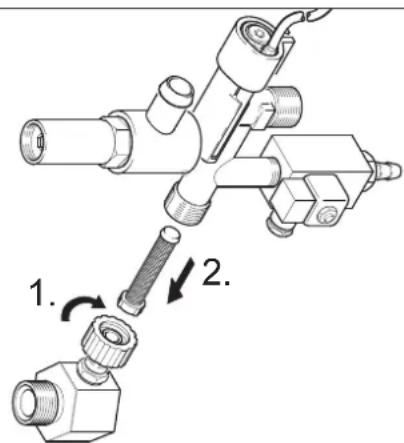
Unscrew the M8x30 screws from the mesh filter. Remove the screws and the mesh. Clean the filter parts. Reassemble in reverse order.
Adjustable electric drives
The electric drives must be adjusted in accordance with the following data:
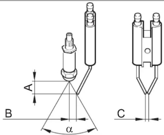
| A | B | C | a | |
| HDS 9/14 4,5±0,5 3,5±0,5 3+0,5 60° | ||||
| HDS 12/14 3,5±0,5 3,5±0,5 3+0,5 60° | ||||
Valve opening
The valve opening in the pipelines is set by the manufacturer. The manufacturer is not responsible for incorrect adjustment of the valve opening.
DANGER
Danger of electric shock! Before opening the valve, disconnect the power supply. Ensure proper grounding of the device.
DANGER
Danger of chemical burn from acid! Wear protective goggles and protective gloves.
Bka3iBa: DToPmMyTeCn IHCTpyKcui 3 BnKOpNCtAHHaHTnΦpN-3y.
3aIITeIOBepxvB6ak3NONnABKOM3BnAaHnAHTnOpN3. BCTaHOBTnPiB BNXOOM BNCOKO TNCKy BiINOBiHy EMHICTb. → YbIMKHyTN npncTpi i DaTH NMy nonpaHOBaTN, DOKN cnpaLIOE cnCTema 3anobirahn y pa3i HecTAY BODN B6ky 3 nonJaBcEM i npncTpi He BIMKHeTbcra. Lc TaKo3 3axnCT BiD Kopo3ii.
ДономORA y BINAДКу HENOLAДOK
△HE6E3NEKA
He6e3neKa mpa8myaHnHa! Peep npoeedeHHm pemOHmHX po6im ma po6im no mexHiHomy o6cIyOByeAHHIO cnId bUMKhymu 20- nOBHu Bumukay a6o eID'cdHamu omekepHu po3'em Cekon.
| Hecnpabnictb Mochimnbipruchnyu Yuchenhny KHM | ||
| Пистрий не пацюс, конт- OLTьна лamма rotobhocst do роботи(F)He ropitb. | У пистои не мас ec hapуг. Пеер: Спрацьогалacхема з ratDNHHNKo- ВIMm MEXAHizMOM Ta 6bOKyBaHnYam. | Ельстрий ВИКлочити на який сас,notim Знову BKVLOchNTi. |
| Переторов ЗанobixkHnK у lanziO3i Керувань(F3).ЗanobixkHnK уст- Новлий у керуочуmpaHop- Matopi(T2). | Вставити Новий зanobixkHnK, pri nOBtopho- у Мпереторянii усуну пчunHypepeBaH- Тжени. | |
| Hecnpabnii MaHOMetpruChn Bv- Мыкau HD (BvCOKOro TnCKy) abo ND (Nt3bKOro TnCKy). | Перевиртii MaHOMetpruChn BvIMNKauch.Слух Ба пдзрмkn Користувayib | |
| Hecnpabnii Таймер мodyя(A1). | Перевиртii пд'еданн, pri Neobxidnocti Замин. Слух. Користувayib | |
| Спрацьогв Термocstat BiDpaць- Ваних ra3iB(B8). | Дату установци oxonoluyn, Po3bIokovbyat# Термocstat BiDpaцьованix ra3iB(B8).Ус- Нуtn priunhy Heçрabnoci. | |
| + Горь Контрльна лamма перетричу Двигун(a). | Спрацьогв Термодачн(KS) у Двигуни abo ВIMNKaч ристою за- хисту BiDпереван taxeь(B1). | Усуну писиу поеван taxeIGN.Слух; Ба пдзрмkn Користувayib |
| Спрацьогв пис,则Зanobigагнay у рazi BiDcTNoCTi Bodi B 6aky 3 Nonlabuem. | Усуну Heustayu Bodi.Користувay | |
| Пальник не заелюсь баб noLum'mя rache pi'd qac eKcnpnyatauüi | PerugЯTop Tempepatуri(B) уст- новлий на заадю НИЗуКу Tem- пepaтуу. | Установittа за和完善OTОу ругларota більш ВИСOKU Tempepatуу. |
| ВIMNKaч рис,则ОпepebyBaE He на пальни. | Вklючтii пальни.Користувay | |
| ВiklJOeNoTo pис,则ОпepebyAн 得 ВIDcTNoCTi Bodi ZANobixHoro БLOky. | ЗбeЗпeчтii Достаиму пожу Bodi. Пеpe- Вори пис,则 HepeMeTnHicTb. | |
| 3acBiyeTBSC kontrponha лamма HeCpavBhoCTi пal- нika(E)* | Палivнь бak nopoxhni.Залпьka | палпьа.Користувay |
| Завно паловиф phlbtp. | Очир,则паловиф phlbtp,дяlaцьог В- Крут,则 паловиф phlbtp,Очир,则пta 3HO- By BKVpynti. | |
| ФOTOЕмент Датчika поу' Невиро Спreamobань abo Ис- равни. | Перевир,则правлбиCitь BCTANOBlenny ФOTOЕмent.** | |
| ВIDcsTney icKpa ZanapLIOBANHry (zzo Видно чepe3 огладove cklo в Крши пальни. | Перевир,则ВIDcastahm Miké leekropondami Траимсфоматoga ВИСOKoi NaPryu n i kabe- лесуЗд�ь. ВIDpergynobatru BIDcSTAnb abo zaminHTHne Heçрabnii detani.у ВИпаду HeobxIDnocti ONUCTH. | |
| Завно паловин пальни. | Усуну,并КуВань.ВИдал,则пproбу(I) на пьы,则 куВань.Tа рozbIKOуВATN BIMi- Кач рис,则Зanotу bIDпereBaHTaxeHb. 3нову BCTABITN pro66k. | |
| Небладу паловин пальни. | Перевир,则detani ta зamihitng Heçрabnii | |
| МагнIHTOО паловио Клалана. | detani. | |
Bka3ibKa:BmKHyTu Ta yBIMKHyTu yCTaHObky, 06 po36nOkyBaTu HecnpabHicTb naIbHnka.
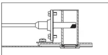
| Hecnpabnictb Moxjnlbni prinu | Ycunhny Ucynenry KIIM | ||
| TorpntkohtpOJIbHa lamna3azmcty bID hakiny (H) | Bikopncstobvbatn nom'ekuybauch.ДоLHTN noM'ekuybach. KopncSTyBaU | ||
| HeodocstatnnoJodaua abo bId-cythictb noadai mInho 3a-cobuy | UcTaHOBtNi Do3yUChn KIaPAnu yNoJoxeHnra"0". | Bidpernyllobatn do3yUChn KIaPAnu MInHoRo3acobuy. | KopructyBaU |
| 3a6HToΦiNbTp MmHOrO 3acObuyablo npoxhni 6ak i3 mInHm 3aco-6om. | OChnstn abo 3aIITN. KopncSTyBaU | ||
| Проруckань abo 3a6HtI BCMOKTu-BaIbHI shaHr n IIniI noadci MmHOr- ro 3acObuy,do3yUchI abo marHITHi KIaPAnu. | IpepeBipNTn,OnCCTNtN. KopncSTyBaU | ||
| HecnpabHa eneKtponHa cnsTeMa abo marHITn KIaPAnu. | 3amHITn Cnyk6a NiDTPMkn | kopncSTyBaivB | |
| Tnck y pinnctpoi He 36ilb-shuetybce | ПюdUTn Форсуну.ЗamHITN hacaIky.КорncSTyBaU | ||
| Iporoxhni 6ak dIЯ MmHOrO 3ac-6by. | ДOLHTN MmHn 3acIb. KopncSTyBaU | ||
| HedocstathBo BODn. 3a6e3neuHTn | OcStaTHNO noadCu BODn. KopncSTyBaU | ||
| 3a6HtI CItuaCTnФiNbTr NaBxOdi BODn. | IpepeBipNTn,po36bpaTn ta oOcHCTNtN cIteu-CTN φIbTp. | KopructyBaU | |
| HerepmetuHni Do3yUChn KIaPAnu MmHOrO 3acObuy. | IpepeBipNTn Ta yUcInbHn. | KopructyBaU | |
| HerepmetuHni ShaHr noadCu MmHOrO 3acObuy. | 3amHITN KopncSTyBaU | ||
| 3aTnCHytN noPnAusbcevBn KIaPAnu | IpepeBipNTn leKicbXoDu. | KopructyBaU | |
| HerepmetuHni 3aOp6iXhN KIaPAnu. | IpepeBipNTn peryIbOanBuHn, pri notpebi BCTaBHTN HOBe yUcInbHnEHN. | Cnyk6b niDTPMkn KopncSTyBaivB | |
| HerepmetuHni abo BcTaHOBnE-NiHa naTO H3bke 3aueHEnn KIaPAnu peryIbOanBuHn noadCu. | IpepeBipNTn eJeMeHn KIaPAnu, pri BnBnBLeHni yUckOJxHEnb 3amHITN, pri 3a6bpydHn-Hi OChCTNtN. | Cnyk6b niDTPMkn KopncSTyBaivB | |
| HecnpabHni MarHITN KIaPAnu yCisTeMi ckiDaHn TnCKy. | 3amHITN MarHITN KIaPAnu. | Cnyk6b niDTPMkn KopncSTyBaivB | |
| Hacoc BVCOKOro TnCKy cty-kae, ctrpinka MaHOMetpa cka-ue | HecnpabHni demnFep. | 3amHITN demnFep. | Cnyk6b niDTPMkn KopncSTyBaivB |
| Bodaryn HACOC nIcDMOKTuE HeBa-rato nobitpr. | IpepeBipNTn yCMOKTuBaHn CyCTeMy Ta prn-b6patn BVtIKaHN. | KopructyBaU | |
| Pinnctpii npri NpIckluoyHompyruHOMy nIcToIeTI-pOzIIIOB-aCti noctii HOBKNUOaCtBcTa Ta BVKLIQUaCtBcR. | 3aKypopena foPocyHnB a CTrpumH-Ni trpybci. | IpepeBipNTn,OnCCTNtN. KopncSTyBaU | |
| Y pincptoi YTBoripBCra NakuN. | ДИВ. po3dIN "BmDaneHn HAcKinny". | KopructyBaU | |
| 3mHeNa ToCkA BcKIOUeHNn CTpyMu nepeBaehaTAtKeHN. | 3aHOBO BcTaHOBtNi 3aueHEnn CTpyMu nepeBaHTaKeHN. | Cnyk6b niDTPMkn KopncSTyBaivB | |
| 3a6HtI CItuaCTN foJIbTp y CIs-CTeMI zAnobigAHn BIDcyTHOCTI Bo-DNI. | IpepeBipNTn,po36bpaTn ta OnCCTNtN cItea-CTN φIbTp. | KopructyBaU | |
| Ppi 3aKpHtOMy puHOMy nIcToIeTI-pOzIIIOB-aCti prin-CTpii He BVMnKaCtBcR. | 3 Hacoca He NobHCTro BIDkaUaHe nobItpr. | UcTaHOBtNi BmMKAca PrinCtPOU B NoLoXeH-Na "0" Ta BITARHyTN pyUHHn PiCToLE-TpOzPi-NIOBau,poKni 3ФocpyHKn He nepeCTaHe BVcTynATn piCtpii. | KopructyBaU |
| HecnpabHni ZAnob6iKnn KIaPAnu abo yUcInbHnEHN 3aOp6iXHoro Kla-naHa. | 3amHITN ZAnob6iKnn KIaPAnu abo yUcInbHnEHN. | Cnyk6b niDTPMkn KopncSTyBaivB |
Akececyapn
3acic6 dIy uHnEHH
BukopncTahnHa 3ac06y dny uHneHH nonerWye npouc oHneHH. Y tabnui npedctabJeHo nepenik 3acobid nayuHenn. NpeD BHKOpncTahnHM 3ac06iB dny uHneHH OOB'3KOBOPoHTaTN Bka3IBN Ha ynakobui.
| Сфера зacructуваима 3аб rudенни, ти п зacructуваимя | Миночи зacrubs зacruchны рH (при-ну в поportовдни вор di) | ||
| Вантужни обтоюни, бениковни, Trан-cspordно- ekспendини arentstва, Trансторгл rocssnodapства | Пил, Влични б rud, мінералы масгалда (на лakованix nobер-xнях) | RM 55 ASF ** 8 | |
| RM 22/80-noporшok ASF 12/10 | |||
| RM 81 ASF 9 | |||
| RM 803 ASF 10 | |||
| RM 806 ASF 11 | |||
| Конserваця обтою вимя 42х олodни bick дя оочиени пid ви-cokим тисkom | 8 | ||
| RM 820-rapачни bick ASF 7 | |||
| RM 821-bick, ёо розпresься, ASF 6 | |||
| RM 824-Super-Perlwachs ASF 7 | |||
| RM 44 reелевий оочиени obodíв 9 | |||
| Металообroduна поми-snobivь | Масгалда, кonsistentэнни зmaшиени, пил i lnшi подбни зб rudенни | RM 22-noporшok ASF 12 | |
| RM 55 ASF 8 | |||
| RM 81 ASF 9 | |||
| RM 803 ASF 10 | |||
| RM 806 ASF 12 | |||
| RM 31 ASF (слььни зб rudенни) | 12 | ||
| RM 39-pidкni (з корозійник засостом) | 9 | ||
| Плдриемства 3 пеpe-робкихарчobих пcodук-tib | Заб rudенни bID лески до сe-peдніх, кonsistentэнни зmaшиени/масгалда, більшi поberхни. | RM 55 ASF 8 | |
| RM 81 ASF 9 | |||
| RM 882 reелевia пінa OSC | |||
| RM 58 ASF (пінотьорни мінii засib) | 9 | ||
| RM 31 ASF * | 12 | ||
| Димчasts kaniфаль | RM 33 * | ||
| Очшени та Dežinфекция | RM 732 | ||
| Дezinфекция | RM 735 | ||
| Нakл, мінералы bідklade徳нray | RM 25 ASF * | ||
| RM 59 ASF (очшени пін{o}) 2 | |||
| Сантарно-TEXИЧА ra-lузв *** | Вално, сецовий камінь, мілno то-ц. | RM 25 ASF * (основе оочиени) | |
| RM 59 ASF (очшени пін{o}) 2 | |||
| RM 68 ASF 5 |
* = TlBKn DnA KopoTkoUacHOrO 3aCToCyBaHn, DBoeTaHn Cnoci6, nicra OunuHn HpOMtN XoJIoHO BDOIO ** ASF nerka cenapobaHictb ** nIa nonpeDnBoro po36pN3KyBaHHB BIKOpNCToBvEbCraFoam-Star 2000
MOHTAXO6NaHaHHa

Tilbkn dna ABtopn3ObaHoro nepcohany!
3araanbhi noJoxeHHa
-HarpibaIbHm npncTpoem e naiNBHeBa yCTaHOBka. Ipn yctaHOBci cIId doTpMyBaTnCra npnncaHb, 0o diOt b y ci kpaHi. -BukopncToBbAtn TInbKn nepeBipeni DImapi /tpy6onpOBoDn DnBIBOBy BIDnpaCboBaHnx ra3iB.
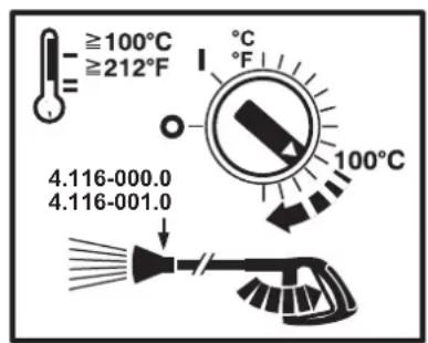
Ppno pobounx TempepaTpyax noHa 100 ° C NOMIHrtn fOpcyHKn BnCOKOrO TnCKy Ha napoBi fOpcyHKn.
Attention! These symbols are necessary for every device.
Tank with year of manufacture
When installing a tank with a year of manufacture in a room where devices are installed, it is necessary to follow the instructions for storing filled tanks (can be ordered from the publisher Carl Heymanns Verlag, Cologne, www.heymans.com).
Level indicator
When laying heating pipes, follow the diagram below.
The system consists of two lines: supply and return lines.
- Maximum cross-section of the pressure line: 0.05 MPa (0.5 bar) - Maximum dilution with fuel filter and pump: 0.04 MPa (0.4 bar)
Length of the immersion tube (m)
Height of the immersion tube (m)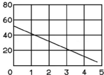
Possible length of the immersion tube when using a tube with a nominal internal diameter of NW 8
Pipe for the flue gas outlet
- Each device must be connected to its own flue gas pipe. - Gas pipes must be installed in accordance with local regulations and agreed with a competent ventilation expert.
We recommend installing a shut-off valve between the device and the flue gas outlet.
Note: To achieve the heating parameters, the values indicated in the "Technical Data" section must be observed.
Before installation, check the mains water supply and the connecting pipes for leaks. The flexible material included in the delivery set should be attached to the pipe. For pipes made of building stone, concrete, and reinforced concrete, it is necessary to use a compensator and a bracket, for example, an anchor compensator (see layout diagram in the manufacturer's drawing). - Fig. 3 - Pos. 19 and 23
The device must not be connected directly to the water mains or to a high-pressure pipeline. It is mandatory to install connecting flanges.
- Fig. 3 - A
Shut-off valves between the water mains and the connecting flange
INSTALLATION OF HIGH-PRESSURE FLANGES
High-pressure flanges must comply with applicable standards.
- The pressure drop in the pipeline must be less than 1.5 MPa. - The prepared pipeline must be checked with a pressure of 28 MPa. - The pipeline must be thermally insulated for temperatures up to 155 °C
Installation of tanks with a minimum means
Fig. 3 - Pos. 20
The tanks must be installed in such a way that their lower level of the minimum means is not more than 1.5 m below the device, and the upper level is not above the device.
Water supply connection
Fig. 3 - B and pos. 19
The water supply is connected to the water mains using a flexible water hose. - The water pressure must be at least 1300 J/hour at a pressure of at least 0.1 MPa. - The water temperature must be below 30°C.
Electrical connections
The maximum permissible resistance of the protective conductor to the mains (see Technical Data). In this case, if you are not given a protective conductor of the mains electrical connection, connect it to the protective grounding system.
The plug connection may cause a short circuit. In case of unfavorable mains conditions, damage to other devices may occur.
- Connection to the mains. Technical data and factory plate. - Electrical connections must be made by an electrician and comply with IEC 60364-1. - Current-carrying parts, cables, and devices in the work area must be in a safe condition and protected from accidental contact.
DANGER
To avoid dangerous incidents during the use of the electrical appliance, we recommend using sockets with a residual current device (max. 30 mA of rated residual current).
Properly connect to the electrical mains.
Install the electrical connection.
The activation of the stationary high-pressure unit is carried out by the main switch, which locks with a key (Fig. 3, pos. 6), located in a safe and easily accessible place.
The contact opening width of the main switch must be at least 3 mm.
Electrical connection via plug connector/socket
Mount the plug connector with different sections on the supply cable. Insert the plug connector into the socket.
The connection of the stationary high-pressure unit to the mains must be easily accessible.
First commissioning
→ Before using, cut the cable ties on the cover of the container with the oil of the water pump.
Instructions for use
DANGER
Danger of explosion! Only use water or light fuel oil for filling. The use of other fuels, e.g., gasoline, is not permitted. Fill the fuel tank.
CAUTION
Operation with salt water or when fuel is present can damage the fuel pump. Before operating with salt water, ensure fuel supply.
Fig. 3 - Item 14
Note: The EASY!Lock system, thanks to the quick-release threaded connection, allows components to be connected quickly and reliably with one turn.
→ Connect the high-pressure hose to the spray gun, then install the high-pressure connection device or the high-pressure hose line.
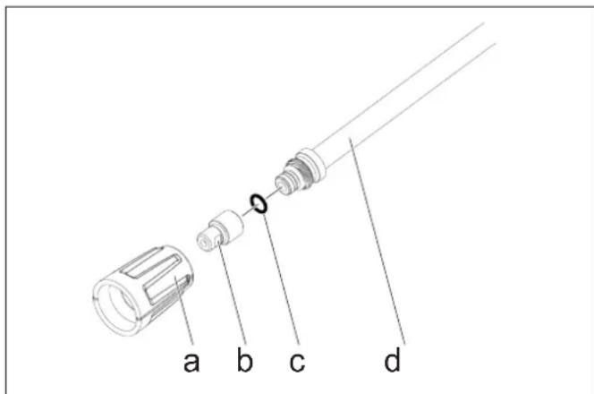
→ Screw the union nut (a) onto the spray gun (b) on the spray tube (d). Make sure that the sealing ring (c) fits exactly in the groove.
Protection against backflow
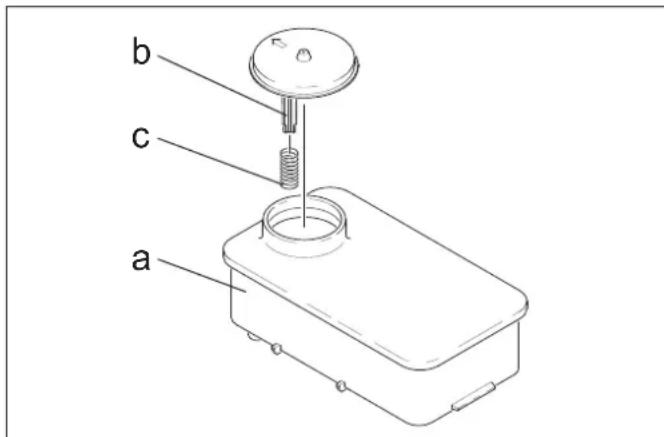
→ Remove the spray gun (c) from the trigger (b) of the tank (a). Fill the tank with Kärcher RM 110 (order no. 2.780-001).
DANGER
Danger of electric shock! Installation work must only be carried out by qualified electricians.
→ Determining water hardness: - via the municipal water supply company, - with the water hardness test strip (order no. 6.768-001). → Remove the cap from the device. Open the water inlet with the control knob.
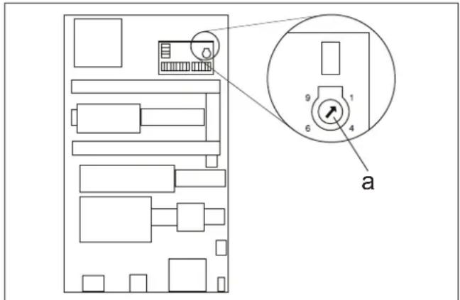
Set the rotary potentiometer (a) according to the water hardness. The correct settings are indicated in the table.
Set the position on the rotary potentiometer to 15°D. This means that the pause time is 31 seconds, i.e., every 31 seconds the magnetic valve opens for a short time.
| ТердICTь Bodи (°dH) 5 10 | 15 | 20 | 25 | |||
| Шkaли поboropot Horo поten- цiomетра | 8 | 7 | 6 | 5 | 4 | |
| Час палу (секун) 50 40 31 | 22 | 16 |
Adjusting the readiness time
The readiness time is adjusted on the large knob on the left side of the electric unit.
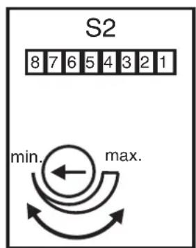
At the factory, the readiness time is set to the minimum value, which is 2 minutes, and can be increased up to a maximum of 8 minutes.
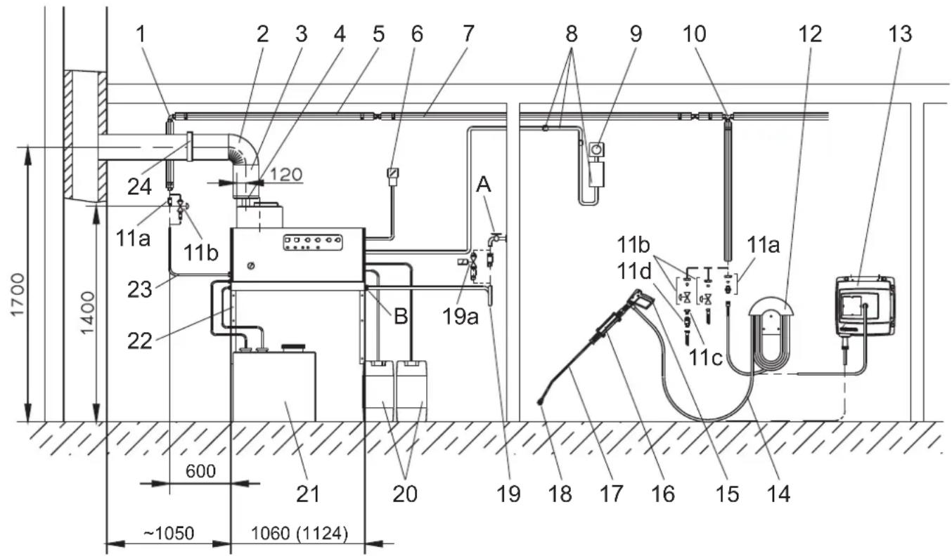
Fig. 3
Corresponding Directive EC
2014/68/EU
2006/42/EG (+2009/127/EG)
2014/30/EU
Category of device
II
Conformity assessment method
Module H
Pressure equipment
Error in responsibility of the language
Spare parts
Error in responsibility of clause 4.3.3
Control block
Error in responsibility of the language
Various pipelines
Error in responsibility of clause 4.3.3
Applied harmonized standards
EN 55014-1:2006+A1:2009+A2:2011
EN 55014-2: 2015
EN 60335-1
EN 60335-2-79
EN 61000-3-2: 2014
HDS 12/14:
EN 61000-3-3: 2013
HDS 9/14:
EN 61000-3-11:2000
Special specifications:
AD 2000 for 3 times
TRD 801 for 3 times
Name of authorized representative:
For 2014/68/EU
Chairman of the Board of Management
Director Regulatory Affairs & Certification
Authorized representative for documentation:
S. Reiser
Alfred Kärcher SE & Co. KG
71364 Winnenden (Germany)
Tel.: +49 7195 14-0
Fax: +49 7195 14-2212
Winnenden, 2018/10/01
Warranty. The warranty conditions of the relevant sales company apply for each country. We will eliminate possible faults in the device free of charge within the warranty period, provided that they are caused by material or manufacturing defects. In case of warranty claims, please contact your dealer or an authorized customer service center with the purchase receipt.
Customer Service
Register your product and benefit from many advantages.
www.kaercher.com/welcome ★★★★★
Rate your product and tell us your opinion.
www.kaercher.com/dealersearch
Alfred Kärcher SE & Co. KG
Alfred-Karcher-Str.28-40
71364 Winnenden (Germany)
Tel.: +49 7195 14-0
Fax: +49 7195 14-2212




- WARRANTY
- ENVIRONMENTAL PROTECTION
- PLEASE DO NOT RELEASE ENGINE OIL, FUEL OIL, DIESEL AND PETROL INTO THE ENVIRONMENT. PROTECT THE GROUND AND DISPOSE OF USED OIL IN AN ENVIRONMENTALLY-CLEAN MANNER
- NOTES ABOUT THE INGREDIENTS (REACH)
- DANGER OR HAZARD LEVELS
- DANGER
- WARNING
- CAUTION
- ATTENTION
- SYMBOLS ON THE MACHINE
- GENERAL NOTES ON SAFETY
- STATUTORY REQUIREMENTS, GUIDELINES AND RULES
- WORK-STATIONS
- PERSONAL SAFETY GEAR
- PROPER USE
- QUALITY REQUIREMENTS FOR WATER
- FUNCTION
- SAFETY DEVICES
- SAFETY MECHANISM AGAINST LACK OF WATER IN SWIMMER TANK
- SAFETY MECHANISM AGAINST LACK OF WATER IN SAFETY BLOCK
- PRESSURE SWITCH
- SAFETY VALVE
- FLAME MONITORING
- OVER-CURRENT PROTECTION
- EXHAUST THERMOSTAT
- PRESSURE RELEASE IN THE HIGH PRESSURE SYSTEM
- SAFETY CATCH
- DEVICE ELEMENTS
- OPERATING FIELD
- START UP
- RIANGLE WARNING
- POWER CONNECTION
- OPERATION
- △DANGER
- SAFETY INSTRUCTIONS
- OPENING/CLOSING THE TRIGGER GUN
- REPLACE THE NOZZLE
- MAKING THE PLANT READY FOR OPERATIONS
- SWITCH-OFF IN CASE OF EMERGENCY
- SET WORKING PRESSURE AND FLOW RATE
- APPLIANCE SETTING
- ADJUSTING THE PRESSURE/QUANTITY REGULATION OF THE TRIGGER GUN (OPTION)
- OPERATING WITH COLD WATER
- OPERATING WITH HOT WATER
- OPERATING WITH STEAM
- WITHOUT PRESSURE/QUANTITY REGULATION AT THE TRIGGER GUN
- WITH PRESSURE/QUANTITY REGULATION AT THE TRIGGER GUN (OPTION)
- OPERATIONS STAND-BY
- SELECTING THE NOZZLE
- DETERGENT DOSING
- REFILLING THE SOFTENER
- SHUTTING DOWN
- AFTER OPERATION WITH DETERGENT
- TURN OFF THE APPLIANCE
- SHUTDOWN
- STORAGE
- TRANSPORT
- CARE AND MAINTENANCE
- MAINTENANCE CONTRACT
- CLEANING THE SIEVE
- SIEVE IN WATER INLET
- FIGURE 1 - POS
- SIEVE IN THE WATER SHORTAGE SAFE GUARD
- ELECTRODE SETTING
- DESCALING
- PERFORMANCE
- FROST PROTECTION
- DRAIN WATER
- FLUSH DEVICE WITH ANTI-FREEZE AGENT
- TROUBLESHOOTING
- ACCESSORIES
- DETERGENT
- INSTALLING THE PLANT
- GENERAL
- FUEL TANK FOR HEATER
- FUEL PIPES
- SMOKE PIPE
- WALL MOUNT
- INSTALLING THE HIGH PRESSURE CONNECTIONS
- INSTALL THE DETERGENT TANK
- FIGURE 3 - POS
- WATER SUPPLY
- FIGURE 3 - B AND ITEM
- ELECTRICAL CONNECTION
- FIRMLY INSTALLED ELECTRICAL CONNECTION
- ELECTRICAL CONNECTION WITH PLUG/SOCKET
- INITIAL STARTUP
- MEASURES TO BE TAKEN BEFORE START-UP
- EXAMPLE
- ADJUSTING THE OPERATIONS STAND-BY TIME
- EU DECLARATION OF CONFORMITY
- CUSTOMER SERVICE
- SIGNATURE
- HAZARD LEVEL
- HAZARD LEVELS
- OVERFLOW PROTECTION
- STRAINER IN WATER SUPPLY
- DANGER LEVELS
- FAREGRADER
- △FARE
- GUARANTEE
- RISK LEVEL
- GARANTI
- ADJUST STANDBY PERIOD
- TAKUU
- SYMBOLS ON THE DEVICE
- EYYUNON
- SYMBOL ON THE DEVICE
- GENERAL SAFETY INFORMATION
- LOCAL REGULATIONS AND DIRECTIVES
- WORKSTATIONS
- PERSONAL PROTECTIVE EQUIPMENT
- OPERATING MANUAL
- WATER QUALITY REQUIREMENTS
- CONTROL PANEL
- COMMISSIONING
- CONNECTION TO POWER SUPPLY
- PREPARING THE DEVICE FOR OPERATION
- SWITCH OFF IN CASE OF AN EMERGENCY SITUATION
- ADJUSTING THE OPERATING PRESSURE AND OUTPUT RATE
- SETTINGS ON THE APPLIANCE
- SETTING THE PRESSURE/QUANTITY REGULATOR ON THE MANUAL SPRAY GUN (OPTIONAL)
- WORKING WITH COLD WATER
- OPERATION WITH HOT WATER
- STEAM OPERATION
- WITHOUT PRESSURE/QUANTITY REGULATOR ON THE MANUAL SPRAY GUN
- WITH PRESSURE/QUANTITY REGULATOR ON THE MANUAL SPRAY GUN (OPTIONAL)
- READINESS FOR OPERATION
- NOZZLE SELECTION
- DOSING OF CLEANING AGENT
- FILLING THE DETERGENT TANK
- AFTER USE, RINSE WITH CLEANING AGENT
- SWITCHING OFF THE APPLIANCE
- DELIVERY HEAD IN METERS (M)
- FLUE GAS PIPE
- WALL-MOUNTED INSTALLATION
- FIG. 3 - POS. 19 AND
- FIG. 3 - A
- INSTALLATION OF HIGH-PRESSURE HOSES
- INSTALLATION OF DETERGENT TANKS
- FIG
- POAABOBBI
- PNC.3-BNNO
- NEKTPNUECKOE NODCOEHHEHNE
- BHIMAHHE
- ONACHOCTB
- KECTKO CMOHTNPOBAHHOE NOCOEHNHEHNE K 3JIEKTPNUECKO CETN
- NEKTPNUECKOE NOCOEINHHENC C NOMOUBIO WTEKEPHORO PA3BEMA/PO3ETKN
- FIRST COMMISSIONING
- COMMISSIONING PROCEDURE
- FIG. 3-ITEM
- PROTECTION AGAINST BACKFLOW
- △WARNING
- SERVICE DEPARTMENT
- REGULAR CHECKS
- GENERAL SAFETY NOTES
- REGULATIONS, GUIDELINES, AND STANDARDS
- INFORMATION ON INGREDIENTS (REACH)
- CNMBOJNHA YPEDA
- YKA3AHNA 3A 6E3ONACHOCT
- PA3NPOE6N, DAPEKTHBN NPABNNA
- PA60THMECTA
- NEPCOHAJIHO 3AUNTHO 6OPYDBAHE
- INTENDED USE
- THE DEVICE AGAINST LACK OF WATER IS INTENDED FOR A BLOCK
- PNEUMATIC SWITCH
- PRESSURE VALVE
- FLAME CONTROL
- OVERHEAT PROTECTION
- FLUE GAS THERMOSTAT
- DISCHARGE OF THE HIGH-PRESSURE SYSTEM
- SAFETY LOCK
- DEVICE COMPONENTS
- SERVICE AREA
- START-UP IN OPERATION
- MAINTENANCE
- OPENING/CLOSING THE SPRAY GUN FOR HIGH-PRESSURE CLEANING
- CHANGING THE NOZZLE
- PREPARING FOR OPERATION
- SWITCHING OFF THE DEVICE
- ADJUSTING THE WORKING PRESSURE AND THE AMOUNT OF SUPPLY
- THE REGULATOR IS ADJUSTED TO THE PRESSURE/QUANTITY OF WATER FOR THE RINSE (OPTIONAL)
- RINSE MODE
- BURNER MODE
- WITHOUT ADJUSTING THE PRESSURE/QUANTITY OF THE NOZZLE FOR DIRECT SPRAYING
- WITH ADJUSTMENT OF THE PRESSURE/QUANTITY OF THE NOZZLE FOR DIRECT SPRAYING (OPTIONAL)
- READY FOR OPERATION
- WEAR PROTECTIVE CLOTHING
- STOPPING OPERATION
- WORKING WITH THE DEVICE
- WALL INSTALLATION
- INSTALLATION OF THE FLUE GAS PIPE UNDER HIGH PRESSURE
- ARRANGEMENT OF THE RESERVOIRS FOR CLEANING AGENTS
- FIGURE 3 - ITEM
- WATER CONNECTION
- PERMANENT ELECTRICAL INSTALLATION
- ELECTRICAL CONNECTION WITH WRENCH/CONTACT
- FIRST START-UP
- MEASURES BEFORE START-UP
- PROTECTION AGAINST VAPOR FORMATION
- ADJUSTING THE TIME UNTIL READY FOR OPERATION
- EC DECLARATION OF CONFORMITY
- RISK OF INJURY
- △CAUTION
- GENERAL SAFETY INSTRUCTIONS
- RISK LEVELS
- INSTRUCTIONS FOR USE OF COMPONENTS (REACH)
- SAFETY LEVELS
- INTENDED USE, DIRECTIVES AND STANDARDS
- HEB63NEKA
- WATER QUALITY
- LEAK CONTROL
- OVERLOAD PROTECTION
- THERMOSTAT FOR EXHAUST GASES
- PRESSURE GAUGES IN THE HIGH-PRESSURE SYSTEM
- ELEMENTS OF THE DEVICE
- PAHENBYNPABNHH
- BVEDEHNB EEKNIYATAUIO
- △NONEPEDXEHNA
- PIIKLUOYENHA DO DKEPETA TOKY
- EKNPNYATAIA
- HEBE3NEKA
- SAFETY
- SAFETY RULES
- OPENING/CLOSING THE SPRAY GUN
- SPRAY NOZZLE
- CHECK READINESS FOR OPERATION
- SWITCHING ON IN THE STANDBY MODE
- SET THE WORKING PRESSURE AND PUMP OUTPUT
- DEVICE ADJUSTMENT
- PRESSURE REGULATOR FOR SPRAY GUN ON MANUAL SPRAY GUN (OPTION)
- SPRAY GUN
- MAINTENANCE AND SERVICING
- CLEAN THE SIEVE FILTER
- SUPPIMER
- ADJUSTABLE ELECTRIC DRIVES
- VALVE OPENING
- ДОНОМORA Y BINAДКУ HENOLAДOK
- △HE6E3NEKA
- AKECECYAPN
- ACIC6 DIY UHNEHH
- MOHTAXO6NAHAHHA
- TILBKN DNA ABTOPN3OBAHORO NEPCOHANY
- ARAANBHI NOJOXEHHA
- TANK WITH YEAR OF MANUFACTURE
- LEVEL INDICATOR
- PIPE FOR THE FLUE GAS OUTLET
- INSTALLATION OF HIGH-PRESSURE FLANGES
- INSTALLATION OF TANKS WITH A MINIMUM MEANS
- FIG. 3 - POS
- WATER SUPPLY CONNECTION
- FIG. 3 - B AND POS
- ELECTRICAL CONNECTIONS
- PROPERLY CONNECT TO THE ELECTRICAL MAINS
- ELECTRICAL CONNECTION VIA PLUG CONNECTOR/SOCKET
- INSTRUCTIONS FOR USE
- FIG. 3 - ITEM
- ADJUSTING THE READINESS TIME
Brand : Kärcher
Model : HDS 9144 St
Category : Heating