WWP 45 - Water pump Kärcher - Free user manual and instructions
Find the device manual for free WWP 45 Kärcher in PDF.
| Product type | Dirty water pump |
| Brand | Kärcher |
| Model | WWP 45 |
| Use | Outdoor, fresh water transport only |
| Maximum flow rate | 45 000 l/h |
| Max suction height | 7 m |
| Max delivery height | 25 m |
| Engine type | Single-cylinder 4-stroke, air-cooled |
| Displacement | 196 cm³ |
| Engine power | 5.1 kW / 6.9 HP |
| Fuel | Unleaded gasoline, min. 88 octane |
| Fuel tank capacity | 3.6 L |
| Runtime | 2.1 h |
| Engine oil | 0.5 L, type 10W-30 or 15W-40 |
| Spark plug | F5T, F6TJC, F7TJC |
| Dimensions (L × W × H) | 580 × 440 × 450 mm |
| Weight (without fuel) | 36 kg |
| Warranty | According to country conditions, against material and manufacturing defects |
| Spare parts | Use exclusively original Kärcher accessories and spare parts |
| Maintenance | Air filter cleaning every 50 h (10 h in dusty environment), oil change every 100 h |
| Safety | Do not use indoors, risk of explosion; wear hearing and eye protection; min. distance 2 m from flammable objects |
Frequently Asked Questions - WWP 45 Kärcher
User questions about WWP 45 Kärcher
0 question about this device. Answer the ones you know or ask your own.
Ask a new question about this device
Download the instructions for your Water pump in PDF format for free! Find your manual WWP 45 - Kärcher and take your electronic device back in hand. On this page are published all the documents necessary for the use of your device. WWP 45 by Kärcher.
USER MANUAL WWP 45 Kärcher
Director Regulatory Affairs & Certification
71364 Winnenden (Germany)
Tel.: +49 7195 14-0
Fax: +49 7195 14-2212
Winnenden, 2018/10/01
Contents
General notes
Intended use
Environmental protection
Accessories and spare parts
Scope of delivery
Safety instruc
Device description
Initial start-up
Initial startup.
Operation
Transport
Storage
Care and service
Troubleshooting guide
Warranty.
Technical data
EU Declaration of Conformity
General notes

Read these original operating instructions and the enclosed safety instructions before using the device for the first
time. Proceed accordingly.
Keep both books for future reference or for future owners.
Intended use
This waste water pump must not be operated in enclosed spaces and is only approved for outdoor operation.
This waste water pump is not approved for use in the food industry.
Only fresh water may be delivered using the pump. Using the pump for inflammable substances such as petrol, diesel or heating oil is prohibited due to the danger of fire and explosion.
Delivering salt water, acidic chemicals and other corrosive substances can damage the pump.
As delivered, this waste water pump is intended for use at heights of up to 1500m above sea level. It can be adjusted by an authorised Customer Service department for use at higher elevations.
If a device that has been adjusted for use at higher elevations is used below this height then this can result in destruction of the motor through overheating.
Environmental protection

The packing materials can be recycled. Please dispose of packaging in accordance with the environmental regulations.
Electrical and electronic appliances contain valuable, recyclable materials and often components such as batteries, rechargeable batteries or oil, which is handled or disposed of incorrectly.
which is intended or disposed of incorrectly - can pose a potential threat to human health and the environment. However, these components are required for the
8 correct operation of the appliance. Appliances marked
8 by this symbol are not allowed to be disposed of together with the household rubbish.
8 Notes on the content materials (REACH)
8 Current information on content materials can be found at: www.kaercher.com/REACH
Accessories and spare parts
Only use original accessories and original spare parts. They ensure that the appliance will run fault-free and safely.
Information on accessories and spare parts can be found at www.kaearcher.com.
Scope of delivery
Check the contents for completeness when unpacking. If any accessories are missing or in the event of any shipping damage, please notify your dealer.
Safety instructions
Hazard levels
△DANGER
- Indication of an imminent threat of danger that will lead to severe injuries or even death.
WARNING
- Indication of a potentially dangerous situation that may lead to severe injuries or even death.
CAUTION
- Indication of a potentially dangerous situation that may lead to minor injuries.
ATTENTION
- Indication of a potentially dangerous situation that may lead to damage to property.
Safety instructions
DANGER
- Danger of injury.
The device is not intended for use by persons with restricted physical, sensory or mental abilities or those lacking in experience and / or lacking in knowledge.
Children must be supervised to prevent them from playing with the device.
Children and minors must not use the device. - Danger of explosion.
- Never operate the device in potentially explosive environments.
- Observe the corresponding safety instructions when operating the device in hazard zones (e.g. a petrol station).
- Only fill the fuel specified in the operating instructions.
- Only refuel with the engine switched off.
- Do not refuel in confined spaces.
Smoking and open flames are prohibited. - Ensure that no fuel gets on hot surfaces during refuelling.
- Close the fuel tank cap after refuelling.
- Do not operate the device if fuel has been spilt. Move the device to another location and avoid generating sparks.
- Store fuel only in approved containers.
- Do not store fuel in the vicinity of open flames or devices having an ignition flame or that generate sparks (e.g. oven, heating boiler or water heater).
- Do not spray start spray into the air filter.
- Danger of fire.
-
Maintain a minimum distance of 2m between inflammable objects and the muffler.
-
Do not operate the device in forests, bushy or grassy areas unless the exhaust pipe has been equipped with a spark catcher.
- Keep grass and other soiling substances away from the cooling fins.
- Do not operate the device if the fuel system is damaged or leaking. Check the fuel system regularly.
- Allow the device to cool down before storing in closed rooms. Danger of electric shock
- Do not touch the spark plug or ignition lead when the device is in operation.
WARNING
Health risk
- Exhaust gases are toxic. Never breathe in the exhaust gases. Never operate the device in confined spaces. Ensure sufficient ventilation and extraction of the exhaust gases.
Make sure that no exhaust gases are emitted close to air vents.
- Avoid repeated or prolonged contact with fuel or engine oil and do not inhale the fuel vapours.
CAUTION
- Danger of burns
- Do not touch any hot parts such as the muffler, cylinder or cooling fins. Danger of hearing damage
- Do not operate the device without a muffler. Check the muffler regularly and have a damaged muffler replaced.
ATTENTION
- Risk of damage
- Use only spare parts from the original manufacturer.
- Old fuel can lead to deposits in the carburettor and impair the engine performance. Use only new fuel.
- Do not adjust any control springs or linkages that might
increase the speed of the engine.
- Do not operate the device with the air filter removed.
- Do not pull the starter cord while the device is running.
- Ensure adequate ventilation so that the device does not overheat.
- Drain all water from the pump if there is a danger of frost.
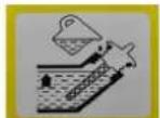
Symbols on the device
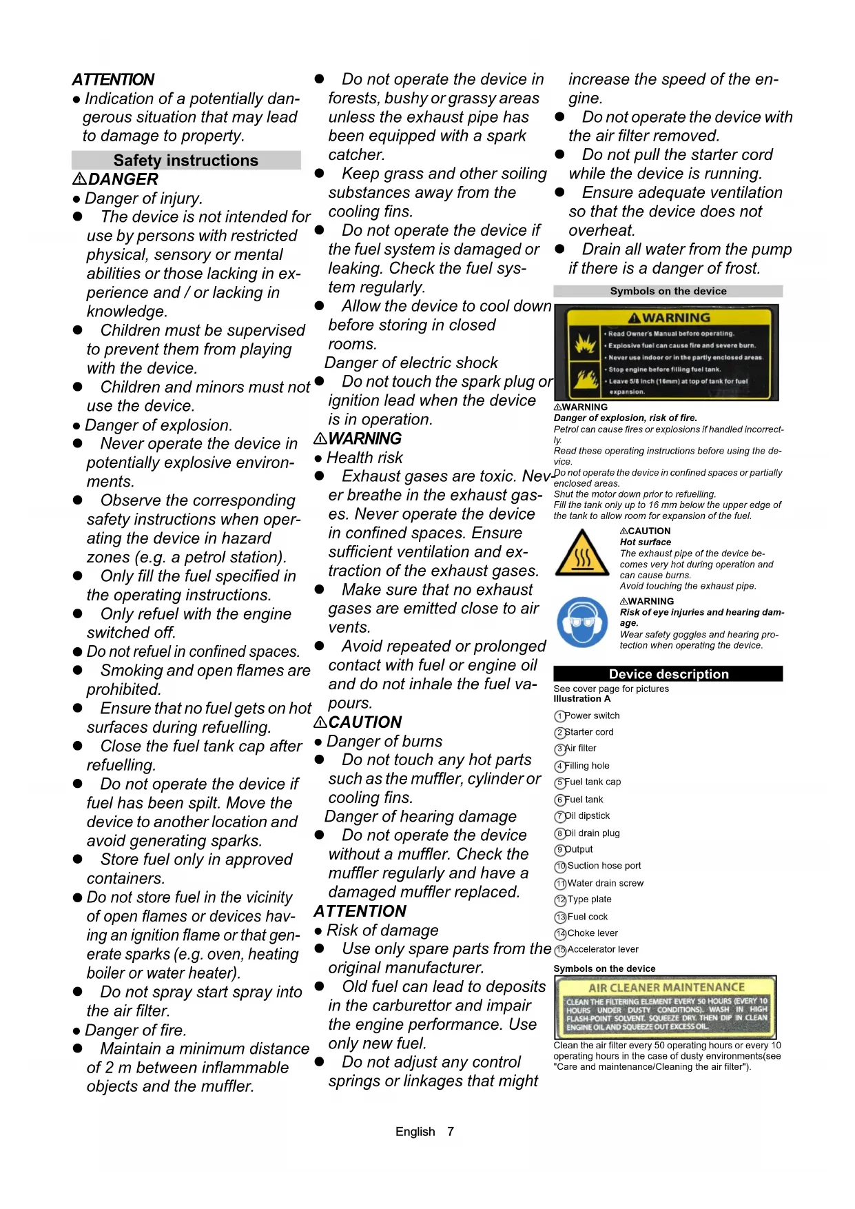
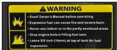
△WARNING
Danger of explosion, risk of fire.
Petrol can cause fires or explosions if handled incorrectly.
Read these operating instructions before using the device.
Do not operate the device in confined spaces or partially enclosed areas.
Shut the motor down prior to refuelling. Fill the tank only up to 16mm below the upper edge of the tank to allow room for expansion of the fuel.
CAUTION
Hot surface
The exhaust pipe of the device becomes very hot during operation and can cause burns. Avoid touching the exhaust pipe.

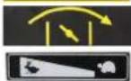
WARNING
Risk of eye injuries and hearing damage.
Wear safety goggles and hearing protection when operating the device.
Device description
See cover page for pictures. Illustration A
1 Power switch
(2) Starter cord
(3)Air filter
(4) Filling hole
(5) Fuel tank cap
(6) Fuel tank
7 Oil dipstick
(8) Oil drain plug
Output
(10)Suction hose port
(1)Water drain screw
12Type plate
13Fuel cock
(14)Choke lever
(15)Accelerator lever
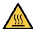
Symbols on the device
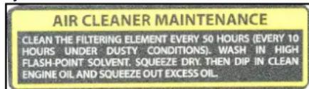
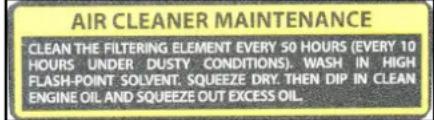
Clean the air filter every 50 operating hours or every 10 operating hours in the case of dusty environments(see "Care and maintenance/Cleaning the air filter").
Note on checking the oil level.
Choke lever
Accelerator lever
Initials
Fill with oil
- Position the device on a level surface.
- Unscrew the oil dipstick.
- Fill with engine oil.
Note: The engine oil is not included in the scope of delivery. The filling quantity and oil type are specified in the section "Technical data".
- Wipe off the oil dipstick.
- Insert the oil dipstick as far as it will go, but do not screw in.
- Pull out the oil dipstick. The oil level must lie in the marked section of the oil dipstick.
-
Top up the engine oil if the level is too low.
-
Screw in and tighten the oil dipstick
Initial startup
Check the oil level
- Position the device on a level surface.
- Unscrew the oil dipstick.
- Wipe off the oil dipstick.
- Insert the oil dipstick as far as it will go, but do not screw in.
- Pull out the oil dipstick. The oil level must lie in the marked section of the oil dipstick.
- Top up the engine oil if the level is too low.
- Screw in and tighten the oil dipstick.
Refuelling
- Unscrew the fuel tank cap.
- Fill fuel up a maximum of the lower edge of the filling nozzle.
- Fit the fuel tank cap and screw tight.
Positioning the pump
The delivery performance of the pump is heavily dependent on the operating conditions. Adhering to the following rules will ensure optimum performance.
- Keep the height difference between the water surface and the pump as small as possible.
- Position the pump so that the suction hose is a short as possible.
A long pressure hose is better than a long suction hose.
Do not unnecessarily long hoses.
Connecting the hoses
- Push the hose clip onto the suction hose. Illustration B
Suction hose (not in scope of delivery)
(2) Hose clip
(3)Hose nipple
(4) Union nut
5 Flat seal
- Slide the union nut onto the hose nipple.
- Push the suction hose onto the hose nipple.
- Position and tighten the hose clip.
-
Fit a flat seal between the suction nozzle and hose nipple. Note: A reinforced hose suitable for vacuum applications must be used for the suction hose.
-
Connect the suction hose to the suction nozzle and tighten the union nut.
- Fit the suction filter to the other end of the suction hose.
Illustration C
(1) Suction hose (not in scope of delivery)
②Hose clip
(3)Suction filter
- Fit a hose nipple, union nut and hose clip to the pressure hose (not included in the scope of delivery).
- Fit a flat seal between the hose nipple and outlet.
- Connect the pressure hose to the outlet and tighten the union nut.
Operation
Venting the pump
ATTENTION
Risk of damage
The seals will be damaged if the pump runs dry. Vent the pump before starting. If the pump is accidentally run dry then stop the engine immediately and allow the pump to cool down before starting the venting procedure.
- Unscrew the cap from the filler opening.
- Fill the pump completely with water.
- Screw the cap back into the filler opening and tighten.
Starting the device
- Vent air from the pump.
- Open the fuel cock.
- Push the choke lever to the left.
- Push the accelerator lever to approximately 1/3 of the total range.
- Set the power switch to "l"
-
Pull the starter cord slowly until a strong resistance is discernible then pull strongly.
-
Slowly return the starter cord.
ATTENTION
Risk of damage
A rapidly returning starter cord damages the device.
Slowly return the starter cord.
8. Push the choke lever to the right once the engine has started.
9. Push the accelerator lever to the left until reaching the desired speed. The flow rate of the pump depends on the engine speed.
10. Check the function of the pump. Dry running damages the pump. Switch off the engine and repeat venting of the pump if the pump does not deliver water.
Switching the device off in an emergency
- Set the power switch to "0".
Switching off the device
- Push the accelerator lever all the way to the right.
- Set the power switch to "0".
- Close the fuel cock.
Draining the water
- Unscrew the water drain screw.
- Allow the water to drain from the pump.
- Unscrew the cap from the filler opening.
- Flush the pump with fresh water
- Allow the fresh water to drain away.
- Screw the cap into the filler opening and tighten
- Screw in and tighten the water drain screw
Transport
- Set the power switch to "0" before transport.
- Allow the engine to cool down for at least 15 minutes before loading.
- Keep the device horizontal during transport to prevent fuel from spilling out.
- When transporting in vehicles, secure the device against rolling away, slipping and tipping according to the respectively applicable guidelines.
- Be aware of the weight of the device during transport.
Storage
CAUTION
Failure to observe the weight
Risk of injury and damage
Be aware of the weight of the device during storage.
ATTENTION
Risk of damage
Do not place any heavy objects on the device.
Store the device in a dry and dust-free place.
Cleaning the device
The device must be cleaned before storage.
1. Allow the device to cool down for a half-hour if it was recently in operation.
2. Flush the pump with clear water.
3. Manually wash the exterior of the device with a small amount of water.
4. Rub all accessible surfaces dry.
5. Unscrew the water drain screw and allow the water to drain out.
6. Screw in and tighten the water drain screw.
7. Lightly oil rust-prone surfaces
8. Spray the control elements with silicone spray.
Storage duration of 1...2 months
- Add petrol stabiliser to the fuel tank.
- Top up the fuel tank.
Storage duration of 2...12 months
Additionally:
1. Close the fuel cock.
2. Place a container under the carburettor. Illustration D
①Carburettor
(2)Prain screw
- Unscrew the drain screw.
- Collect the fuel in the container.
- Screw in and tighten the drain screw.
- Empty the settling cup (see "Care and Maintenance/ Cleaning the settling cup").
Storage duration longer than 12 months
Additionally:
- Unscrew the spark plug.
- 5...10 cm Add engine oil to the cylinder.
- Slowly pull the starter cord several times to distribute the oil in the engine.
- Screw in the spark plug.
- Change the oil (see "Care and Maintenance/Changing the oil").
- Pull the starter cord slowly until a strong resistance is discernible.
Care and service
DANGER
Danger of injury from electric shock
The device can start unintentionally. You can be injured by moving parts.
Remove the spark plug connector before performing any maintenance work.
CAUTION
Danger of burns.
Hot device components cause burns if touched.
Allow the device to cool down before working on it.
See "Startup" for a description.
* See "Maintenance work" for a description.
Maintenance intervals
Each time before use
- Check the device for correct condition and operational safety. Do not start up a damaged device.
- Check the oil level.
- Check the air filter.
Once after 1 month or 20 operating hours
- Change the oil.
Every 3 months or 50 operating hours
- Clean the air filter.
Perform cleaning more frequently in a dusty application environment.
Every 6 months or 100 operating hours
- Change the oil.
- Clean the settling cup.
- Check and clean the spark plug.
- Clean the spark catcher (not included in the scope of delivery).
Annually by the authorised Customer Service
department
- Check and adjust the valve play.
- Clean the fuel tank and fuel filter.
- Replace the air filter insert.
- Replace the spark plug.
- Check/adjust the idling mixture speed.
- Check/adjust the valve play.
- Check the pump impeller
- Check the gap between the casing and impeller.
- Check the pump inlet valve.
Every 2 years by the authorised Customer Service department
- Check the fuel line and replace if necessary.
- Clean the engine combustion chamber.
Maintenance work
Check the air filter
- Lift the strap and remove the cover. Illustration E
1 Cover
②Lap
③ Air filter insert
- Check the air filter insert for soiling. Clean the air filter if necessary or replace if damaged (see "Cleaning the air filter").
- Fit the cover and latch into place.
Cleaning the air filter
ATTENTION
Risk of damage
Penetrating dust can destroy the engine if the air filter insert is absent.
Do not operate the device without an air filter insert.
1. Open the air filter (see "Checking the air filter").
2. Remove the air filter insert.
- Wash the air filter insert in warm water and household cleaner then rinse with clear water. Note: Dispose of the oil contaminated washing solution in an environmentally friendly manner.
- Allow the air filter insert to dry.
- Saturale the air filter insert in clean engine oil and press out the excess oil.
- Fit the air filter insert back into place.
- Fit the cover.
- Close the latches.
Changing oil
Illustration F
Perform the oil change on a warm engine.
1. Unscrew the oil dipstick.
Oil dipstick
(2) oil drain plug
2. Unscrew the oil drain screw with seal and catch the escaping oil.
3. Screw in and tighten the oil drain screw with seal. 4. Position the device on a level surface.
5. Measure the correct quantity of engine oil (for oil type see "Technical data") and fill through the oil dip-stick hole.
6. Check the oil level (see "Starting up").
7. Screw in and tighten the oil dipstick
8. Dispose of the old oil in accordance with the environmental regulations.
Cleaning the settling cup
The settling cup separates water from the petrol.
1. Close the fuel cock.
2. Unscrew the settling cup.
Illustration G
① Settling cup
② Screw
3. Remove the settling cup with O-ring.
4. Clean the settling cup and O-ring using a non-inflammable solvent and allow to dry.
5. Fit the settling cup and O-ring and screw tight.
6. Open the fuel cock.
- Check the seal between the settling cup and carburettor.
- Close the fuel cock.
Checking and cleaning the spark plug
- Pull off the spark plug connector. Illustration H
① Spark plug connector
② Spark plug
- Clean the region around the spark plug to prevent dirt from entering the engine when the spark plug is removed.
- Unscrew the spark plug
- Replace a spark plug that has worn electrodes or a broken insulator.
- Check the electrode gap of the spark plug. Target value 0.7...0.8 mm.
- Check the spark plug seal for damage.
ATTENTION
Risk of damage
A loose spark plug can overheat and damage the engine. An overtightened spark plug can damage the thread in the engine. Observe the following instructions for tightening the spark plug.
7. Carefully screw the spark plug in by hand. Do not cross the thread.
8. Screw the spark plug all the way in using the plug spanner and the tighten as follows. a Tighten a used spark plug by an additional 1/ 8...1/4 turn.
b Tighten a new spark plug by an additional 1/2 turn. 9. Plug on the spark plug connector.
Troubleshooting guide
Have all checks and work on electrical parts performed by an expert.
In case of any malfunctions not mentioned in this chapter, contact the authorised Customer Service.
The engine does not start.
- Open the fuel cock.
- Push the choke lever to the left.
- Set the power switch to "I".
-
Fill the tank with fuel
-
Check the oil level and top up if necessary.
- Clean the fuel tank and carburettor. Refuel with fresh fuel.
- Check the spark plug (see"Care and maintenance/ Checking and cleaning the spark plug").
- Allow a wet spark plug to dry. Then start the engine with the accelerator lever at the full speed position
- Clean the settling cup (see "Care and Maintenance/ Cleaning the settling cup").
Low engine performance
- Check the air filter
- Clean the fuel tank and carburettor. Refuel with fresh fuel.
Pump does not deliver any water
- Vent air from the pump.
- Check the suction hose for leaks and holes.
-
Check the flat seal between the device and the suction hose.
-
Use a more sturdy suction hose.
- Completely immerse the suction filter.
- Clean the suction filter
- Position the pump closer to the water source. Reduce the height difference between the pump and water surface.
8. Use shorter hoses.
Low delivery rate
- Check the suction hose for leaks and holes.
- Check the flat seal between the device and the suction hose.
- Use a more sturdy suction hose.
- Completely immerse the suction filter. 5. Clean the suction filter.
- Position the pump closer to the water source. Reduce the height difference between the pump and water surface.
- Use shorter hoses
Warranty
The warranty conditions issued by our relevant sales company apply in all countries. We shall remedy possible malfunctions on your appliance within the warranty period free of cost, provided that a material or manufacturing defect is the cause. In a warranty case, please contact your dealer (with the purchase receipt) or the next authorised customer service site.
(See overleaf for the address)
Technical data
WWP 45
Pump
Weight without fuel kg 36
| Nominal width* 3 | |||
| Maximum flow rate l/h 45000 | |||
| Suction height (max.) m | 7 | ||
| Delivery height (max.) m | 2 | 5 | |
| Internal combustion engine | |||
| Engine type Single-cylinder | |||
| Type | 4-stroke | ||
| Cooling type | Air-cooled | ||
| Engine capacity | cm3 | 196 | |
| Engine performance | kW/PS | 5,1/6,9 | |
| Fuel type | Petrol, min. 88 octane | ||
| Fuel tank capacity | l | 3,6 | |
| Working time with a fully filled fuel tank | h | 2,1 | |
| Engine oil volume | l | 0,5 | |
| Oil type | 10 W-30 | ||
| 15 W-40 | |||
| Spark plug type | F5T, F6TJC, F7TJC | ||
| Dimensions and weights | |||
| Length | mm | 580 | |
| Width | mm | 440 | |
| Height | mm | 450 | |
CO2Emissions according to the measurement procedure of EU regulation 2016/1628 Euro V
| Motor | g/kWh | 790 |
| Subject to technical modifications. | Currently applicable EU Directives2006/42/EC (+2009/127/EC)2014/30/EU2011/65/EU | H. JennerChairman of the Board of ManagementS. ReiserDirector Regulatory Affairs & Certification |
| EU Declaration of Conformity | ||
| We hereby declare that the machine described below complies with the relevant basic safety and health requirements in the EU Directives, both in its basic design and construction as well as in the version placed in circulation by us. This declaration is invalidated by any changes made to the machine that are not approved by us. | Harmonised standards usedEN 809: 1998: A1: 2009 + AC: 2010EN 61000-6-3: 2007+A1: 2011+AC: 2010EN 61000-6-1: 2007 | Documentation supervisor: S. ReiserAlfred Kärcher SE & Co. KG |
| Product: Waste water pump | Conformity evaluation procedure used2000/14/EC: Appendix V | Alfred-Kärcher-Str. 28 - 4071364 Winnenden (Germany) |
| Type: 1.812-xxx | The signatories act on behalf of and with the authority of the company management. | Ph.: +49 7195 14-0Fax: +49 7195 14-2212Winnenden: 0210/10/04 |
Contenu
Remarques generales. 10
2006/42/CE (+2009/127/CE)
2014/30/UE
2011/65/EU
Chairman of the Board of Management
S. Reiser
Director Regulatory Affairs & Certification
Responsible de la documentation : S. Reiser
Alfred Karcher SE & Co. KG
Alfred-Karcher-Str. 28 - 40
71364 Winnenden (Germany)
Tél.: +49 7195 14-0
Telécopie: +49 7195 14-2212
Winnenden, le 01/10/2018
Indices
Chairman of the Board of Management
S. Reiser
Director Regulatory Affairs & Certification
71364 Winnenden (Germany)
Tel.: +49 7195 14-0
Fax: +49 7195 14-2212
Winnenden, 01/10/2018
Inhoud

H.Jenner
Chairman of the Board of Management
S. Reiser
Director Regulatory Affairs & Certification
71364 Winnenden (Germany)
Tel.: +49 7195 14-0
Fax: +49 7195 14-2212
Winnenden, 2018/10/01
Indices de contentsos
Avisos generales 20
Uso previsto 20
Protection del medioambiente 21
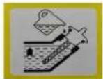
CLEAN THE FILTERING ELEMENT EVERY 50 HOURS (EVERY 10 HOURS UNDER DUSTY CONDITIONS), WASH IN HIGH FLASH-POINT SOLVENT, SQUEEZE DRY. THEN DIP IN CLEAN ENGINE OIL AND SQUEEZE OUT EXCESS Oil.
2006/42/CE (+2009/127/CE)
2014/30/UE
2011/65/UE
Chairman of the Board of Management

S. Reiser
Director Regulatory Affairs & Certification
Responsible de documentacion: S. Reiser
Alfred Karcher SE & Co. KG
Alfred-Karcher-Str. 28 - 40
71364 Winnenden (Germany)
Tel.: +49 7195 14-0
Fax: +49 7195 14-2212
Winnenden, 01/10/2018
- Levantar as abas e remover a tampa. Figura E
Chairman of the Board of Management

S. Reiser
Director Regulatory Affairs & Certification
Representante da documentacao: S. Reiser
Alfred Karcher SE & Co. KG
Alfred-Karcher-Str.28-40
Winnenden, 01/10/2018
Indhold
www.kaercher.com/REACH
2006/42/EF (+2009/127/EF)
2014/30/EU
2011/65/EU
2000/14/EF: Tillaeq V
Chairman of the Board of Management

S. Reiser
Director Regulatory Affairs & Certification
71364 Winnenden (Germany)
TIf.: +49 7195 14-0
Fax: +49 7195 14-2212
Winnenden, 2018/10/01
Indhold
Generelle merknader 31
2006/42/EF (+2009/127/EF)
2014/30/EU
2011/65/EU
Anvendte harmoniserte standarder
EN 809:1998:A1:2009+AC:2010
EN 61000-6-3:2007+A1:2011+AC:2010
EN 61000-6-1:2007
Chairman of the Board of Management

S. Reiser
Director Regulatory Affairs & Certification
71364 Winnenden (Germany)
TIf.:+49719514-0
Winnenden, 10/01/2018
Inneháll
Allman information 35
EN 61000-6-3: 2007+A1: 2011+AC: 2010
EN 61000-6-1:2007
Tillampad konformitetsbedömmingscedure 2000/14/EG:Bilaga V

H.Jenner
Chairman of the Board of Management
S. Reiser
Director Regulatory Affairs & Certification
Dokumentationsbefullmaktigad: S. Reiser
Alfred Karcher SE & Co. KG
Alfred-Karcher-Str. 28 - 40
D-71364 Winnenden (Germany)
Tfn: +49 7195 14-0
Fax: +49 7195 14-2212
Winnenden, 2018/10/01
Sisaltö
Yleisiä ohjeita 38
Maaraystenmukainen kaytto 38
www.kaercher.com/REACH
Chairman of the Board of Management
S. Reiser
Director Regulatory Affairs & Certification
Dokumentointivastaava: S. Reiser
archer SE & Co. KG
Alfred-Karcher-Str. 28 - 40
71364 Winnenden (Germany)
Puh.: +49 7195 14-0
Winnenden, 2018/10/01
Pepiexóveva
EvikeuToBeiEeI 42
PpOeTROEvn xpnon 42
PooTaa Tou TepiBaaovToC 42
Papekóeva kai avtalaktkia 42
NapaotoeoEgonlaouc 42
YTIOBcEic aopaaeis 42
Pepipapn ouakeuncs 43
Oe ton eIeIoupyia yia npwn qopá 43
Oeon 0e Aetoupyia 43
Aeitoupyia 44
Mεταφρά 44
AToeua 44
2006/42/AT (+2009/127/AT)
2014/30/AB
2011/65/AT
Chairman of the Board of Management
S. Reiser
Director Regulatory Affairs & Certification
Winnenden, 2018/10/01
CodelpkaHne
O6uye yka3aHn 49
IcnoB3oBaHne no Ha3HaueHnIO 49
3aunTaOkpykaHoueIcpebl 49
PnHaJnxHocTn 3aNaChbIyacTn 49
KOMNJIeKT noCTaBKn 49
Yka3aHnno TExHnke 6eOnacHOCTN 49
OnncahHe yCTpoNcTba 50
PepBbI BBOD B 3KcnnyatauHO 51
BbD B 3KcNpyatauH 51
3Kcnnyataa.. 51
TpaHcnpOpBbKa 51
XpaHeHne 51
YxOITexHnueckoe 6cbnyKnBaHne 52
POMOuB npH HEnCnpaBHOCTx 52
TapaHTN 52
Texnueckne xapaKTepeNCTnKn 53
Deknapaun o COOTBETCTBn CTanapTAM EC ... 53
06üne yka3aHn

IpeepnepbimnpmmeHemcYCTPOINCTBAOHAKOMMTcCdaHHOHOpINHABHOBNHCPTyckneiNo
3KcNpyatauIN npnnaeraembIMyka3aHnMNI
TEXHNE 6e3o3nACOCTN. IeCTBOBATB COOTBTCTBNN C HMM.
CoxpaHtB o6oPouOpIe IaIaNbHeNwero nnonbOaHHnIINr dneJeuOooIraaIeI
IcnoJb3OBAHHe no Ha3HaueHnIO
DaHnnbHaocn prrAHOB b3aepueho HcnoIb3OBATb B 3aKpbIbIX NOMEeHnX, OH MOKET pa60Tatb TOnkBo HAuNJIe.
AaHbHaacocIpyraHOH BoBy He OanyeHdIy HcONb3OBAHnB NIIeBOB npOMbUHeHHoCTN. HAcocom 4aPeeaaTcnepeKaunBaTb TOnkBo npceHYO B0yD.
IcnoIb3oBAHne HAcOa IJNepeKaUHbAHnR rOpIOHIX BueCTe: 6Be3NHa, dMJIeN UIN Ma3yT cTpOrO
3aPpeHIO-3a ONaCHOCTN B03rOpAHn INB3pbBa
PnpekauBHH coHOB BObl, KcNtOT, XMMuecknx BwecETB n PpOuX CNoCObCTByIOUxN Kopp03H BeueCTB HACOC BoMgKbTbN POBKeJdE. DaHbH HACOC DnRrHNOB BoB N BoCTaBnREMOm COToHn PpeHa3HaeH dnn 3KcPnYatauHn Ha BbICote He bOeJe 1500 M nad yPOBHeM mOpR. YOnlHOMoUeHHa CnyK6a NoDnepxKKnJIneHTOB MOKET pNeo6pa2oBaTb yCtpoIcTB O nPaobTb Ha BoNBweB BcOTe.
ПиуЗКЛУТацИМТAKOROуСТЮДCTBAHaBbICOTeHnKeToI,ДЯKOTOPОнОнпeоБОБPyDOBaH,ДВгATeNBMOJET6bTHeoBpAHTMIONoBpeXdENBpe3yNbTaTepeperPeba.
3aunta okpykaoue cpebl
YnakoBOUHbI MaTePmaJIbI NoDdAOTcB TOpINuHOI NepepaOToK.EyNkoBky Heo6xOIMO yTInm3HPOBaT bE3 yUepeBaIpn OkpyKaIOUeCpebl.
3neKtpnueckne H 3neKtpoHbIe yctpoCTBa
acto coepxat IeHHbIe MATEpAaIb,
nproHbIe nBTOBpOHNopepe60Kn, IN
3aayctyoTAKMe KOMNOHeHTb.KAK Batape.
aKKyMJIaTOpbI INMaCNo, KOtOpbI pInn HEnpaBnIbHOM O6paueHIM ININ HeHaDNeKaUeey yTNIN3aUIN PnpDeCTabNIOIT NOTeHNuaIbHyIOANOCHsTBJI 3IOPOBBY I 3K0JONrIN. TeM He MeHeE, DaHHBe KOMnoHEHTb Heo6XoDNMbI DnI PaBnIHbHO paBOtbl YcTpoCTBa.YcTpoCTBA,O6O3NaueHbHe 3TNMMBOJOM, 3AnpeSeHO yTNIN3uPOBaTB BmecTe C b6bTOBbIM NTxODAM.
Yka3aHn no nHrpeDneHTam (REACH)
IINIOJNUyEHHA KATyAJbHOH HOpMaUNO6
INHpeDneHTax CM. www.kaercher.com/REACH
PnHaIeXHocTn 3aIacHbIe YactN
IcnoIb3oBaTb TOnIbKO opnHnHaBHeI npHaJIeKHOCTN 3anaChbte YacTH. TOnIbKO OH rapaHTpyIOI 6eOanachyIO I bcnepe6oHy IO paOby yctpoCTBA.
Длп поучени Инфомаши о ріпнадлесьхостя и 3дцотсгмс.CM.Wkaercher.com.
KomnJIeKT NOCTABKIN
Ipn paacnakokBe yctpoiCTBa npoBepntb
KOMNNEkTAuIO. Ipi ObnapyKeHHn HeOCTaOHux
PnHnAaNEXHOCTe HnN NOBpeXDeHH, NOnyHeHHx BO
BvPEMa TpHaCNOPTnPOBKn, CneDyET YbeDoMTb
TOptBOy oprAnH3aUIO, npOdaBHyO yCTPOCTBO.
Yka3aHnno TcXnKe 6e3oNaCHOCTN
CTeneHb onaCHOctN
ONACHOCTb
- Yka3aHue omHocumenbHo HenocpeOcmBEnHO apo3aue onachocmu, Komopar npueodum K mJxKeIbIM mpaemam uNu K cmepmu.
△PENDyNPEXKDEHNE
- Yka3aHue omHocumenbHO 603MOxHO nOmeHuaJIbHO onaCHO cumyaauu, Komopar MOxem npubecmu K mXeIbIM mpaemam UNu K Cmepmu.
△OCTOPOXHO
- Yukazahue Ha nomehuaJIbHO onachyu cumyaauo, Komopam MoXem npueecmu K nolyeHuO JeaKux mpaM.
BHIMAHNE
- Yka3aHue omHocumenbHo 603MOxHOUI nOmeHuuaJIbHO onachou cumyaauu, Komopar MOxem noBney 3a cobou MamepuaIbHbI yuep6.
Yka3aHnNo TExHnKe 6e3ONaCHOCTn
ONACHOCTb
OnachocmbmpaemupoabaHua.
- Ycmpoucmeo He npedha3haueH oJn UcNoIb3O8aHuaJIuamaU c O2paHuueHHbIMU fu3uyeckmu,ceHCOPhbIMU uNu yMcmBeHHbIMU cnocobnocmmyu luu JuaMu c Hedocmamkom onbima u/ uNu 3HaHu.
Cneumb 3a mem, ymo6bl demu He uapanu c ycmpoucmeom.
3aPepaempaobombc ycmpoucmeom demu npodpocmkam.
Onachocmb 63pbiea.
3anpeuamaemcra 3Kcnnyamupoeamb ycmpoucmeo 60 63pbioonacbIX 3OHax.
- Ppu 3Kcnnyamauu ycmpoucmea 6 onachbix 30Hax (HaPpumep, Ha 3anpaBocHyxCmaHucyx) co6nIodamb coombemcmeyuue npabuna mexHuku 6e3onacnocmu.
3aunabmbonbko monnueo, yka3aHHOe uHcmpykuu no 3Kcnnyamauu.
3aIueamb monnubo molbko npu 6bIKIOUeHHOM dbuzamene.
- 3a npabka 3akpbimbix NOMeueHuaX He donyckaemc.
3aPpeueHo Kypmb u pa36oobmb omKpbimbiu 020Hb.
Bo 6pem3a npaku He donyckamb nonadanu monnuea Ha 2opaye noeepxnocmu.
- Nocne 3a npabku 3aKpbimb KpbuKy monnueHo2o 6aka.
He pa3pewaemcna ycmpoucma, ecnu 6bilo npolmo monnueo. Iepenecmu ycmpoucme o dpyoe mecmu u u36eamb6pa30aHua uckp.
XpaHumb monnueo molbko 6 pa3peweHHbIX EMKocmX.
3anpezaemc xpaumb monnueo 6bnu3u omkpblmo20 o2H uU ycmpoucme, uCNoB3yUux 3anaIbHOe nIaMra UU o6pa3yUox uCKpbI (HaNPUMep, neeu, omonumelbHbIX Komnoe UUN bOdoHaaspeameneu).
3anpeucaempaacnbimbaop03oJbDn86bicmp0203anycka 8 603dyuHbIuNbMp.
- Onachocmb noxapa.
PaccmoraHue Mejdy ne2koBocnnaMeHReMbIMu npedMemamu u 2nywumene mdoJxHo cocmaBnmb He meHee 2 M.
- IcnoIb3oamb ycmpoucmeo Ha MecmHocmu, 3acaxeHHou depe6bMyu, Kycmau unu mpaos pa3pewaemcra UCKIOUOpMeIbHO, eCNI bIXIONHa mpy6a ochaueHa UCKPOZAcumelm.
He donyckamb nonadanu mpaabu npoux 3aep3Henu Ha oxnaqdaouue pe6pa.
He uonb3oamb ycmpoucmeo,ecnu monnuehara cume ma noepkdeha unu HezepMemuHa. Heo6xodmo peynpno npoepemb monnuehyo cumemy.
- Pered yknaodkoHa xpaHeHue 3aKpbimom nomeeHuu damb ycmpoucmey ocmbimb. OnachocMb ydapa 3neKmpuueckum mOKOM
He npukacmbcK cbeue uu Ka6enIO 3axu2aHua 6o 6pempa6ombl ycmpoucmea.
△PENEYNPEXKDEHNE
- OnachocmbdЯ3dopoebya
- BbIXnonHbIe 2a3bI ydoobumbl. He bObXamb bIXnonHbIE 2a3bl. 3anpeueho 3Kcnnyamupoabmb ycmpoucmeo e 3akpbimbx nomeuhenx. Heobxodumo obecneumb docmamoyu oehmunrau u omboB ebIXnonHbIX 2a308.
- Y6eumbca, ymo e obnacmu moeyek enycka 0o3dyxa He ebixodm ebixnonHbIe 2a3bl.
- 1362ammb MHO2OKpamHO2o unu dnumenbHO2O cnpukochoehHu Koxu C monnubom unu Momophim MacnOM; He eboxamb monnuehbie napbl.
△OCTOPOXHO
Onachocmb oxoaa
He npukacmbc c 2opyum demanm: nyuumei, unundpy unu pebpam oxnaxdehura.
Onachocmb noepexkdeHua cnyxa
He 3KcIpyamupobamb ycmpoucmeo6e3 anyuumen. Heobxodmo peaynphno npoepeymb anyuumelb u 3aMeHm b e20, ecnu OH nOepexdeH.
BHIMAHNE
- Onachocmb noepexdeHua
- IcnoIb30aMb moIbKO opu2uHaJIbHbIe demanu om npou36Odumen.
Cmapoe monnueo moxem cnpoeoupuoamb o6pa30aHue omnoxeHu8 ka6upamope u, cneobameNbHO,CHuxehue MOuHocmu dBuameJ. HcnoIb30aamb moIbko HOoe monnueo.
3anpeuzaemc u3MeHm b noLoXeHue npyKun pezylmopa uU m2, ymo6bI He yeBnUumb yucno obopomoe deusameJ.
3anpeueho 3Kcnyamupoabmb ycmpoucmeo6e3 603dyuho2o funbmpa.
He mnymb 3a nyckoobu mpoc BO bpema paobmby ycmpoucmea. - Obecneumb docmamoHyo 8ehmuuio 60 u36exaHue nepepeea ycmpoucmba.
- Ecnu okuadomcra cunbhbie Mopo3bl, Heo6xodmo cIumb 6ody u3 Hacoca.
CmBOnbHa yctpoiCTBe
△PENDyNPEXDEHNE
Onachocmb e3pb1ea, onachocmb noxapa.
Ppu HnpaunbHom 6paueenu 6e3uH moxem cmamb npuyuHou nokapa unu e3pbja.
Ipeo ecnofo3oeaehumycpmo1cmea npohummb daHnUHcmpykuu noeknnnyamaauu.
He cnoIb3o8amb ycmpoucmeo 8 3akpbblbx nomuehenx uHa naCmuHo oOpokehHNO meppumopu.
Ipeod 3anpaekou ebiknHcmb deuzamnb.
3aunamb monnoe monko do ommeku 16 MM Hxke
bexhne kpoKmka, ymofo ocmaanocb mecmdo nra
pacuupuehur monnuea.
OCTOPOKHO
Topyra noepxHocmb
BbXnonna mpy6a ycmpoucmeea eoepema 3KcNlnyamaauu cunbHO Haepebaemc u MoJem bI3amb oooU.
U36e2amb KOHmakma c bixnonHou mpyo.

△NPEdynPExkdeHne
Onachocmb noepekdehura cnya uun 3pehu.
Bo epema paobomlc ycmpooucmeo uonnb3o8aembzauumHbte ouku u cpeodma zauumbl opaoahcnyxa.
Onncanhe yctponctBa
1306paekhenmHa o6oPote
Pcyhok A
①BbIKHIOATEnb yCTpoIcTBA
②TpoCobBmCTapTeP
③Bo3dUHbIΦnIbTp
4BamHBoeOTBepCTne
(5) Kpbliika TOnnHoro 6aka
6TOMMBHbB6aK
7Macnon3MepntbHbIyyn
8 Pe3b60BaI npo6ka MacnocnBHOOTBepCTIN
9BbIXOa
10BcabsBaOuOnnNaTpybok
1 Pe3b6oBa npo6Ka cnBHorO OTBepCTnIy BoDbl
②3aBoDcKa Ta6nHa
③TOnnBbMyKpaH
(4) Pbyar npBDA BO3dyuHNo 3acNOHKn
15Pbiarra3a
CNMBONbHa yCtpoIcTBe
OuichiTaB Bo3dyHbHn FmIbTp KaJbIe 50 cAcOB, npn pa6oTe B nIbHbOn cpee —KaJbIe 10 cAcOB (cm. «YxoN TexHnueCKeOe CcIyKnBaHne/OcInCTka Bo3dyHnOrO FmIbTp').

Yka3aHnIO KOHTpOIO YPOBnA MaCna.

PbUar npBODa BO3dyHnOH 3azONHOH

Pbivarra3a
PepBbI BBOD B 3KcNpyaTaunIO
3aJIbKaMaCnA
1.YCTAHOBNTb yCTPOINCTBO rOpN30HTaJIbHO.
2. BbIBHHTNb MacNON3MepuTeNbHbI uyn.
3. 3aHtB MOTOpHoe MacNo.
Yka3aHne: MOTOpHoe MaCNo HE BXOHT B KOMNJIeKT
NoCTaBKn. KoJIHeCteBO H cOPT MaCna Cm. B pa3JeNe
《TexHcEckme XapAKTePcNTKn》
4. BbIepeBb MacNON3MepntenbHbHbI yyn.
5. BCTABITb MaIOHN3MepHTeBnHbN IyU IN DO KOHNa, He 3A8HHNIBA ERO.
6. ⅢaJIeMb MaCIOH3MePHTeBbIy Iuyn. YpOBeHb Macna DoJIKeH HaxOHOITcBcB OMTmeHcHOb IIaCTn MaCIOH3MePHTeBbHOrO Iuyn.
7. Ecm ypoBeHb MaCnA CmNtKOM H3OK,doNITb MOTOPHOE MacNo.
8. BbnttB n 3aTMyb MacNo13MepTeNbHbN uyn
BbD B ekcnnyatauH
PpOBepka ypoBnMaCna
1.YcTaHOBnTb yCtpoIcTB rOpN3OHTaJIbHO.
2. BbBnHTNb Maclon3MepntbHbI yyn.
3. BbIepeTb Macnon3MePeNTbHbI uyn.
4. BCTABITb MaCIOIN3MepHTeHbIy IuynDo KOHua, He 3aBHHVBAE rgo.
5. ⅢBNEuMbACMOIN3MepNTeBbHbIyUPOBEH MacnaDIOJKeHN HAXOIDTBcB OMTMeEHNOIbOaNCTMaCNIO3MEpNTeBbHOrO UyNA.
6. Ecnim ypoBeHb MaCna CnIiKoHOM H3OK,doJIbTb MOTOPHOE MACNo.
7. BBNHTNb 3aTAYHyb MaONN3MePnTeBbHbI yyn.
3anpaBka TOnnHBom
- OTBnHTnTb KpbIuKy TOnnHBO HorO 6aKa.
2.ДоЛNTb TOnNINBO He BbIe HnKHei KpOMKn 3aJIbHOrO naTppy6ka. - HadeMb 3aTMyb KpbIky TOnnBHO 6aka.
YcTaHOBka Hacoca
PIM3BODHTENbHOCTb HACOCA BO MHRoM 3ABNCHT OT yCNOBn Eero pENHeNc. CoBNIOdA CneDyUHNE npABnA,MOXHO Do6BtCB ONTMALBOH MOUHOCTn.
Pashnla BbICOT BOBPEXCTN BOBJI HACOCA DOKHKA 6BtB KAK MOKHO MEHJIe.
- UCTAHOBITb HACOC TAK,TOBbI BCaBbIaOuIe IaHAF bIL IMAKcMAMNbBO KOKOTKM.
IcnoJIbOBeT bnnHnBb HAnOpHbI ShaJIHr BByIOHee, cEm IINHHbI BCacCbBaIOUmShaJIHr.
He nCnONb3OBOBt DnINHbIe ⅢaHnIg 6e3 Heo6XDoIMOnCTo.
PoiKJIIOUeHne UaHroB
- HaneTb xomyT hA BcacbIbaOuN mlaHr. PncyHok B
① BcacbBaHoum nHaHr (He BXoNIT B KOMnJIeKT nocTaBn)
②ⅡIlaNaHroBbIxOMyT
(3)PnncoeDHHTeBbHnNaTpy60kwnHa
4HaKnDnaTaiKa
(5)INOCKoe yNIOHTHeHne
- Hanbetb HAKINHUYO raiy Ka npncoeDnHITeNBHn PNTV60K ⅢNaHa
- HaTeB BCaCbBAHOUHn 1nPaHr Ha npCoeDnHTenBnHn nATpy6ok 1nHaHa.
- YcTaHOBnTB XOMyT Ha MeCTO H3aTARHyTb.
5.YctahOBtB IIOCKOE yIIOOTHEHMe MExNy BCaBbAUOUM nATpyKOM mIPOCoeDINHTeBLHbM nATpyKOM UJHaRA.
PnMMeaHHe: B KaeeCTBe BCacBiaUeTo 7HaHra Heo6XoIMIO NcOIOb3OBAb apmIOPOBaHHb 7NaHr, PpeHna3HaeHHbI dIg 3KcPnIyTaunB yCJNoBxR BakyMa.
6.ПОДСЕДНИТВ BCaBIAIOUIMI WIIANH K BCaBIBAOUeMy NaTpYbKu 3aTЯHyTb HAcNHyO raiKy.
7.HaBTOPM KOHcE BCAbBAHOeero WnHaRA yCTAHOBNTb QINbTp BCaCbBAHn. PNCYHOK C
① BcacbBaHoum WnAHr (He BXoDHT B KOMNJIeKT nocTaBk)
(2)UnaHroBbXOMyT
③ΦMbTp BCaCbBaHn
- HAdEtb Ha HanopHbI WnAhnr (He BxOaNT B KOMNNEkT NocTABK) PnICcEOHNHTeBbH naTy6ok WnAHa, HAKINHyo raKy u WnAhaRboB XOMYt.
9.YCTAHOBNITb NIOCKOE YNLOTNHEHNE MEKdYI pINCOeHNHTeNBHM NaTPy6KOM ⅢJHaHrA IN BIXOXDHMB NATpy6KOM.
10.ПодсоeДиHNTb HanOpHbI WnAHT K BbIXOy I 3aTMyTb HAKmHyO rAky.
3Kcnnyataa
YdaNTb Bo3dyx H3 Haocca
BHIMAHNE
Onachocmb nopekdeHua
Paboma hacoc aecxyu eedem knoepexdehuynomnenuhui.
ydanumb 03dyx u3 hacocapepeeodom e
kcnnyamauio. Ecnu KOcmamupoeaHO, ymo haco
pabomaem cxyyo, Heo6xoHMO HemeOnHe
ocmaohumb deuaenb u damb hacocy ocmbim
pepeyanaehm u3 heo 03dyxa.
- BbIBHHTnTb np6ky 3aJIINBHO O TBePcTna.
- NonHocTbIO 3aONHHTb HaCOC BOHOI.
- CHOBA BvEBPHTb np06ky B 3aJIINBHOE OTBepCTME W 3ATyHBt.
3anyck yctpOcTBA
- YdaHb Bo3dyx H3 Haocca.
- OTKpbITb TOJINBHBbl KpaH.
- OTBeCTn pbIar BO3dyuHoi 3acJNoHKn BneBO
- OTBeCTn pbHar r3a npMepHo Ha 1/3 xOJa BNeBO.
5.YCTAHOBNTB BYBKKIOHTAeYbCTPOIcTBA B NOJONKHeMe -
MedenHNO TNOTAHyTb TPOCOBBI CTAPTEP DO OUYTMORO CONOTINBNEHNA,3aTeM NOTAHyTb 3a TPOC CINBHO.
-
MeiNeHNO OTBECTI TPOCOBBI CTAPTEP H3aD, BHUMAHNE
Onachocmb nospexkdeHua
BbCmpbOeOpemMpocOeOcMapmepa e uXcbHoeNoJaoHeMeMoxem CnpoeUupoeAembnopeJehn yCmpoucme.
MedenHO omecmmu mpocebl cmapmep Haaed. 8. Nocne 3anycka dbratentorBCTn pbyar BoaynuHn 3acnoHNbnpabo.
- OTeBcTn pIaI r3a BIIeBO HAcToNbKO, YTO6bI DoCTHyKHOH YaCTOb I BpaUeHIN Bana DBrAtenr.Ipn03BODInTeHbOcH T hAcocA 3abNCIT OT HaCtOb I BpaUeHIN.
- PpOBePbTb paOry T haCoc. CyXo XoB BpeDHT Haocy. EcNn HACcH eNepeKaHnaBET BOy, Heo6xOIMO oCTaHOBtB DnraTeNb I NOBTOptb NpoceDpy yndaENHa BO3Dyxa n3 HAococ.
AbaHoe OTKIOueHne yCTpoCTBa
- YctahOBHTb BbIKIOUATEIb yCTpoICTBaB nIOJOKeHHe «O»
BbIKIOueHHe ycTPOcTBA
- OTBecn pyuar rasa Bnpabo do KOHua.
2.YctAHOBNTb BbIKIOuATen yCTpOHTBa BnONKeHNE《0》。 - 3aKpbbTb TOnJIINBHyI KpaH.
CnVBoBbI
- BbBHTnb peBbObyu np6ky OTBepCTnI dNJIa CINBA BOdy.
2.Cntb Body n3 Hacoca. - BbIBNHTNb np06ky 3aJIIMBHORO OTBepCTnA.
- Ppombyt b Hacoc CBexKe BDOJ.
5.CNTb CBexkyo BDOy. - BVBHNTIb 3aTAYHBt npO6Ky 3aJIINBHOrO TBEPCTIA.
7.BBHTNb 3aTAYHTy pe3b6BOyO np06ky 0BETPCn4 nCnBA BOdy.
TpaHcnpToPobKa
- Penei TPhaONCINTOPOBOK yUcAHOBHOT BbKIOHOTEny bYcTOPOCTBA BnIOLOKENH
-Даы萌гелюoctытнocneHarpy3Ke He MeHee 15MHVT.
BoBpEmTpaHcnpTnOBkUypeKINBaTb yctpoIcTBoRop3OHTaIbHo,OTobHe npONIOCb TOnIIMBO.
Pnnepeo3ke yctpoCTBa B TpaHcnOpTHbIX cpeCTBax qKcNPOBaT b eO rO CKaTBaHnC KcONbJKeHn INpOKnIBaHnB B COOTBETCBN C DeHCTBYOuMMIN DApKETNAMM - YuHTbIbTaB Bec yCTpoiCTBa npn TpaHcNOpTnpoBKe
XpaHHeHne
△OCTOPOXHO
Heco6nOdeHue 8eca
Onachocmb nonyueHua mpaam u noepexdeHu
Bo epem xpanenu yumbleamb eec ycmpoucmea.
BHIMAHNE
Onachocmb nopekdeHua
He knacmb Ha ycmpoucmeo mxxenble npedMembl.
Ppu xpahehuu bepey ycmpooucmeo om enauz u nbu.
OuNTka yCTpoiCTBa
Neped ydknHa xpaHHe MCTPOBEOHE6XMOO OHCTb.
1.Даь устостовCTOBtOBNoJIaHaca,ecnI He3aIOnIOTO 2TO3O OHO INCNO3B0ABOJcO.
2. PpombbHacoc HcctoBdo
3. O6MbIbY cTPOCTBNO BPYHUYO CHAPyKu HBe0bIbIMM KOHNCTOBM BOBDI.
4. Hacyxo BbTepeBt BCE DoCTynHbIe NOBepxHOcTn.
5.BbIHNTb pe3bObyIO np6ky OTBepTnIg IcNBA BOIu NtBTO BODy.
6. BBNHTnB n 3aTaNHyTB pe3b6OByo np06ky
OTBepCTNIA DnIa CINBA BOdbI
7.CJrKa Cm3aTb MACNOM NOBepXHOCTN, BOCPINMHNBBE K KOPPO3n
8.Cma3aB orpAraHbI ynpAbeNHe CINIOHOBObIM cnpeM.
XpaHHeHne 1-2 Meca
- 063BnTb B TOINNBIHbI 6aK CTa5nM3atOP 6EH3NA.
- 3aONHHTb TOnNHBhB6aK
XpaHeHne 2-12 MecaueB
DOnONHHTeJIbHO:
- 3aKpbbTb TOnJIbBHyI KpaH.
- UcTaHOBtB eMKoCTb nOJ KAp6KopatOp PncyHok D
①Kap60paTop
② Pe3b6oBa npo6Ka cINBHorO OTBepCTH
- BbBnHTntb pe3b6OByIO npo6Ky cIIMBHOrOTBepCTnR.
- Co6paTb TOnJIHBO B EMKOCTb
- BBHNTHTb 3aTReHytpe3b6Obyo np6kYc CNBHorO OTBepCTO.
- OnyctoWntb oTcToHMK (cm. «YxOД nTexHnuecko OcbnyKBAHne/OuNCTKa oTcToHnka»).
XpaHHeHneDolbwe 12 MecaueB
DOnonHnTeJIbHO:
- BbBnHTntb CBeCy 3axnraHna
- 3aInTb B cHnHdp 5-10 cm MOTOPHO macna.
- Heckobko 43 pne MeHHoNotHb 3a Tropocbo stapr npn pncpeDeneHm Macna Bdratenge
- CHOBA BBHHTb CBeuy 3aJnraHna
- 3aMeHnTB MaCNo (CM. «YxoI N TexHnueckoe O6cnyKbAHne/3aMeHa Macna").
- МedlyнEO NOTAHTB TPOCOBB CTAPTep DO OUOTNIMO CONPOTMBHNEIA.
yXoI TeXHnueckoe 06cnyxnbAHne
ONACHOCTb
Onachocmbmpaemupoeahure,onachocmbydapa 3nekmpuueckmuokom.
BoMoXeH cAmOpou3eOnbH bI 3aynck ycmpoicmea. Cyuecmeyem puck haneceHua mpaBn noDbeuxhblmu demaumy.
Ipepe npoeedeHem mExHueeckoo 06cnlykueaHua Hneobxodmo omcoeduHmb wmcencb cebu 3axzuaHua.
OCTOPOXHO
Onachocmb oxoza.
Pnpu npukochoeHHU KOpHUM demamr YcmuOpMeaMOHO NpOHyHM OkoU.
Hn3Ka MOnHOCTb DBnraTeJr
-
PpOBepnB BO3DyUHbI ΦNJIbTp.
-
OcHtntb TOnnmbHbIb 6aK np KAp6OpatOp.3aNtB cBeeKToTOnnIBo.
Hacoc He nepekauBaet Body
1.YdaJIITb BO3dy
- InpoBepHTb repemTNUOCTb BCaBbAIOUEO UJNAHrAn HnJIaHc B HEM BTOPBCTN.
3.Поверпь плоскoe улnotHeHne Мжду yctpoIcTBOMиВссыBAIOUMшЛаHROM.
4.ИспόньбовыБблесСТбиьБьВсасьвацйшагг. - NnHocTbIO norpy3ntb 6nBtp BcacbBAHnA.
- OuHCTNTb fNtBtp BCacbBAHHa
-
NmoeCTInb HAcOC 6nHex K nctOCHky BODbl. YMeHbIHTb pa3HOCTb BbcOT MeKdy HAcOCOM NOBepxHOCTb BOJbl.
-
IcnoIbObaTb OoJe KopoTKe IuHaHr. Hn3ka npOn3BodntbHocb
-
PnOBePHTb repMeTNUOCTb BCaBbAIOUEO UNaHra HAnJHHe B HEM BTOBPCTN.
- NpOBePrtbI NnOcKoe YNIOHTHene MEXdY UCTPOETBOM BNCsBtBAOuIMUJAHrOM
- NcnoIb3ObaTb 60oee Cta6nblbHb BCaCbBaIOUcIM nnHaR.
- NnHocTBIO norpy3NTb FnNtBp BCacbBAHn.
- OuNTb BnBtp BCaCbBAHn
- PomeCTbH aoc 6nHex K nctOCHky BODbl. YmehbHTb pa3HOCTb BbCOT mexdy Hacocom N NOBEPXHOCTb BOJbl.
- Icnonb30BaTb 6oJee KopoTKe WnAhn.
Tapaantma
B kaJdoI cTpaHe DeiCTByIO T COOTBeTCTByIOUne rapaHTHnHbYe yCNOBHaYcTAHOBNHbIe yONHMOueHHo npAHHa3aNeu No CbTy Haewi npOdyKmN. Bo3MoXhBi HeNCpBaHOCTu YcTpoIcTBa B TeHeMe rapaHTHnHOrO cPOKa Mbl YcTpAHRM
6eCnNaTHO, ECNI npNHaH 3aKnIOaHTcB DepeKtax MaTePnaIOB HINI pOnIHBOdCTBeHHbIX 6pAke. B cNyae BOBHKeHOBHe NPeTHeH N TeUHe NrEpaRANTHIHO CPOka IpoCb6a ObaPaTaBc C yekOM O nokyKe B TOROBy OpraH3aUNIO, IpoDaBlyu N3deNne INI B 6bnKaHMy UynONHomOeHHyO cnyk6y cepBncHO 6bCyJbMaHry.
(Adpec yka3aHa o6oPoTe)
Data BbInycka OTo6paKaaEeTcHa 3aBOdckoT aBnueKe B 3aOKOpOBaHOM BnDE.
Pn3TOMOTdIeNbHbIeIuΦpblmEIO Tcndyioee 3haueHHe:
Приимер: 30190
3 roD BbInycka
0 cToJeTHe BbInycka
1 DecTnIeTne BbInycka
9 BTopaa Cua Mecaa Bbnycka
0 nepBaIuΦpa Mecaa BbInycka
TakIM 6pa3OM, B DaHHOM npHMepe K0d 30190 03HaaeT dAty BbInycka 09/(2)013.
TexHnueckne xapaKTepeNCTnKN
| Hacoc | ||
| HOMINAHBLYДиамету"3 | ||
| Pacxod mack. | I/h | 45000 |
| Высota васьваня(Makc.) | m | 7 |
| Высota поаду(Makc.) | m | 25 |
| Диогател Bvyтpenнero cropannna | ||
| Тулдаггалу Odoшлindroрь | ||
| Тул 4-taktnhny | ||
| Тул oxлajdeninna | С ВОЗДУЛБМoxлajdeninne | |
| Равочи obleм | cm3 | 196 |
| Мошисть ддаггалу | kW/PS | 5,1/6,9 |
| Тул толпILA | 6eH3M, MIn. OKТанове чИС lo 88 | |
| Емкость толпьного бака | I | 3,6 |
| Верma paobotу priо палного баke | h | 2,1 |
| Колчесъ моторного масla | I | 0,5 |
| Сорт масla | 10 W-30 15 W-40 | |
| Тул севе зжигалу | F5T, F6TJC, F7TJC | |
| Размрьи и Бec | ||
| Длina | mm | 580 |
| Ширна | mm | 440 |
| Высota | mm | 450 |
| Весь Золпьа | kg | 36 |
| CO2-змбся B coOTьтCTьнс c proцедурии ИЗмерени Согларно рergлamedу EC 2016/1628Еро V | ||
| Диогател | g/kWh | 790 |
| Сохразнегся право на Небесенные Тechнiques Истддгам EC | ||
| Декларачи O coOTьтCTьн STANДAPTAM EC | ||
| Ноставима заavedл.ЧTO кONSДПИЙ, КONТСТУСПЕ I NOLTNENHE YAZAKHIM NOHIX MAJIINH IOBEHAOCT COOTВETYROU M OCSOBHIM TReBбOBANHIM DmpeKTEB INEC no BeZMAHACNCTH NOXAPANE 3DOPOBLY.Прлп NOБХ IMENHIX M MAJINH, He COTLBOANHbC Na Staile KMONMANH, Данный Дддгам Рету.TСБОСИ.ИЗДLE: HACOC Ддгу prazhen BDу | ||
| Тул 1.812-xxx | ||
| Демстуши ддгКВь BC | ||
| 2006/42/EC (+2009/127/EC) | ||
| 2014/30/EC | ||
| 2011/65/EC | ||
| Приименны rapamonsriPoRavBNHs CTANDArtB | ||
| EN 809: 1998; A1: 2009 + AC: 2010 | ||
| EN 61000-6-3: 2007+A1: 2011+AC: 2010 | ||
| EN 61000-6-1: 2007 | ||
| Приименны метod очесни COOTВETBNN | ||
| 2000/14/EC: Плиожende V | ||
| H.Neogen dmncabuimec nIIa DeYCTBYOT OT IMENH IN no DoberpennoCTn Ppavlenia. | ||
| H.J. Jenner Chairman of the Board of Management S. Reiser Director Regulatory Affairs & Certification | ||
| ПлLO, OTВТСТВНОЕ 3A ВIDLENDEДOKUMENTАП. ILI. | ||
| Райser(S. Reiser) | ||
| Alfred Karcher SE & Co. KG | ||
| Alfred-Karcher-Str. 28-40 | ||
| 71364 Winnenden (Germany) | ||
| TeR.: +49 7195 14-0 | ||
| Фанк: +49 7195 14-2212 | ||
| r. Виненьden, 01.10.2018 | ||
| Tartalom | ||
| Altalanos utasitask... | 53 | A csomolgoyanyagujahrasnosilhatto. Kárjuk, környezelbarat modyon semmisitse meg a csoma-golast. |
| RendelteteSzerü hasznalat... | 53 | Az elektromos elektronikus keszülekek értes, üjrahansnosilhatto anyogakot, égyakran olyan alkoztelemeket, peldaal elementek, akku-mulatorokat vay olajt isartalmzak, melyek nem megefello kezellese vay hylteken megesmirite-se potenciális verzétyl jentehet az emberek egészségre é a környezelte. Ezek et al ozlatolelemek azonban a kszülek rendeltete sres zuemelseshez szukségek. AZ ezzel a szimbulmua jelölt keszülekeket nem szabad a haztarasti hulladekkal yegtug megsemissite-ni. |
| Környezelvadelem | ||
| Tartzórekós pólalktrészek... | 53 | Összvetovkre vonatkozó utasitask (REACH) |
| Szállott tartozék... | 53 | Az öszvetovkre vonatkozó aktuális informaciokat ltt ta-lajla: www.kercher.com/REACH |
| Biztonsagi ultasitask... | 53 | Czajtskiy okres konatkozó utasitask (REACH) |
| A keszülk leirasa... | 54 | Az öszvetovkre vonatkozó aktuális informaciokat ltt ta-lajla: www.kercher.com/REACH |
| Elsö uzembe helyezés... | 55 | Czajtskiy okres konatkozó aktuális informaciokat ltt ta-lajla: www.kercher.com/REACH |
| Uzembe helyezés... | 55 | Czajtskiy okres konatkozó aktuális informaciokat ltt ta-lajla: www.kercher.com/REACH |
| Uzemelletés... | 55 | Czajtskiy okres konatkozó aktuális informaciokat ltt ta-lajla: www.kercher.com/REACH |
| Szajtslats... | 55 | Czajtskiy okres konatkozó aktuális informaciokat ltt ta-lajla: www.kercher.com/REACH |
| Tárolas... | 55 | Czajtskiy okres konatkozó aktuális informaciokat ltt ta-lajla: www.kercher.com/REACH |
| Apoias es kardanlarlmas... | 55 | Czajtskiy okres konatkozó aktuális informaciokat ltt ta-lajla: www.kercher.com/REACH |
Chairman of the Board of Management

S. Reiser
Director Regulatory Affairs & Certification
Winnenden, 2018/10/01
Obsah
Obecné poukyny 57
Pouzifv souladus urcenim 57
Ochrana Zivotniho prostre 57
Pfslusenstvl a nahrndnl dlly. 57
Rozsah dodávky 57
2006/42/ES (+2009/127/ES)
2014/30/EU
2011/65/EU
Uporablichen harmonizirani standardi
EN 809:1998:A1:2009+AC:2010
EN 61000-6-3:2007+A1:2011+AC:2010
EN 61000-6-1:2007
Veljaven postopek ocene skladnosti
2000/14/ES:Priloga V
Podpisniki ravnajo po navodilih in s pooblastilom uprave.

H.Jenner
Chairman of the Board of Management
S. Reiser
Director Regulatory Affairs & Certification
Pooblascena oseba za dokumentacio: S. Reiser
Alfred Karcher SE & Co. KG
Alfred-Karcher-Str. 28 - 40
71364 Winnenden (Nemcija)
Tel.: +49 7195 14-0
2006/42/WE (+2009/127/WE)
2014/30/UE
2011/65/UE
Chairman of the Board of Management
S. Reiser
Director Regulatory Affairs & Certification
Administrator dokumentaci: S. Reiser
Alfred Karcher SE & Co. KG
Alfred-Karcher-Str.28-40
71364 Winnenden (Germany)
Tel.: +49 7195 14-0
Winnenden, 2018/10/01
Cuprins
Directive UE relevante
2006/42/UE (+2009/127/UE)
2014/30/UE
2011/65/UE
Norme armonizate aplicate
EN 809:1998:A1:2009+CA:2010
EN 61000-6-3:2007+A1:2011+AC:2010
EN 61000-6-1:2007
Procedura aplicata de evaluates a conformità 2000/14/CE: Anexa V
Semnatarii actioneaza in numele si prin imputernicirea Consiluliiu director.

H.Jenner
Chairman of the Board of Management
S. Reiser
Director Regulatory Affairs & Certification
Insarcinat cu elaborarea documentatiei: S. Reiser
Alfred Karcher SE & Co. KG
Alfred-Karcher-Str. 28 - 40
71364 Winnenden (Germania)
Tel.: +49 7195 14-0
Fax: +49 7195 14
Winnenden, 01.10.2018
Obsah
2000/14/ES: Priloha V

H.Jenner
Chairman of the Board of Management

S. Reiser
Director Regulatory Affairs & Certification
71364 Winnenden (Germany)
Tel.: +49 7195 14-0
Fax: +49 7195 14-2212
Winnenden, 01.10.2018
Sadrzaj
Opé napomene 75

Chairman of the Board of Management
S. Reiser
Director Regulation Affairs & Certification
Opunomocenik za dokumentaciju: S. Reiser
Alfred Karcher SE & Co. KG
Alfred-Karcher-Str.28-40
71364 Winnenden (Njemačka)
Tel.: +49 7195 14-0
Telefaks: +49 7195 14-2212
Winnenden, 1. 10. 2018.
3mict
3araJIbHi Bka3iBKn 78
BukopntaHHa npn3HaeeHHa 78
Oxopoha doBkinna 78
Ppnaa Ta 3anaChi detani 78
KOMNJIeKT NOCTaBKn 78
Bka3iBkn 3Texhikn6e3neKn 78
Onnc npncpo 79
Pepwe BBeDHHB EKcnnyatauio 80
BbeHn Beknnyataio 80
Eknnnyataia 80
TpaHcnpTyBaHH 80
36epiranra 80
Dorra Ta texhuihe o6cyroBaHHa 80
DonomoraBpa3i HecnpaBHOCTe 81
Tapahtia 81
TexhihixapakTepcntkN 81
Deknapaia npo BiNobiHicb CTanapTAMC. 82
3araanbHI Bka3iBKn

Neped nepuBnKOpNCaHHM
nPcTpoO 03HaHOMNTncb 3 UIEIO
OpriHaIbHOIO IHCTpyKJIEIO 3
zangya did yac nobomu I moxe
cnpuunmu oniku.
YHukaume KOHmakmy 3 eunyckHOIO

△NONEPEDXEHH
Puzuk yuKoDxKeHn opaHie cIyXy ma npAeMaYAHn OHeJ.
Ii#vacekcnnyamaufipnucmpo0eukopucmoyeamu 3axuchi okynpura ma zacobu 3axucmy opaahie cnyx.
Onnc npnctpo
PcCynKn DUB. Ha 3BOpOTi
MaJIIOHOK A
1BmmKau npncTPO
②PyuHm cTepTe
(3)TobirpaHmphiBtp
(4)BANBHHM OTBip
⑤ KpnIka naiINBHorO 6aka
6TnBn6ak
7Lyn
⑧ PpO6ka OINHOB3NMBHOOr O TBOpY
Buxi
(10)YCMOKTByaBbHn naTpby6ok
11 Pp6ka BDO3NHBHO O TBOPy
⑫3aBODcbKa Ta6nHa
⑬Паимьнй Кран
(14) Baxinb nobitpnoi 3acnHkn
15DpocseIbHnBaxijb
CnmbonHa npctpoi
AIR CLEANER MAINTENANCE
CLEAN THE FILTERING ELEMENT EVERY 50 HOURS (EVERY 10 HOURS UNDER DUSTY CONDITIONS). WASH IN HIGH FLASH-POINT SOLVENT. SQUEEZE DRY. THEN DIP IN CLEAN ENGINE OIL AND SQUEEZE OUT EXCESS OIL.
OuimataN nobITpHn fIObTp KOKHI 50 roHn, y 3aunneHOMy cepoDBouKoKHI 10 rOIMn (mIB.
[OioiT a TeXHHHe O6cnyroByaHHn / Ouinien Hn NOBITpHoro fIObTPa].
Bka3iBa 0oNo nepeBipKn pIBn OINB.

Baxinb noBirpaHoi 3acnHK
DpoceJIbHnBaXinb
Nepwe BBeDeHHB EeknnyaTaciio
3aINBaHHOJNB
- BcTaHOBHTn npCTpiB TROP3oHTaIbHOMy nOxKeHHi.
2.BukpyTuTn uyn. - 3aIHTM MToPHy OINBy. BkaIbKa: MoTOpHa ONBa He BXOINTb DO KOMNkTeY NOCTABIK. KInbKictb I Mapka ONMB HabeHJI Hi TaBJI [TexHHiXapakTePcNTKN].
- Постерп ун.
- BCTaBHTn 7yn do kiHua, ane He 3akpyyBaTN
- BNTaTn ΜyN, PIBeNb OINBn NOBInH E3HXQDITnCb yNoTHaHEnY TauchIn ΜyNa.
7.3a Hn3bko rO pIBH dONHTM MOTOPHY ONBBy - BkpyTnTn 3aTARHyTn Lyn
BbeHnB Eeknnyatauio
Ipebeipka pIBH oINBn
- BctaHObONI npnCTpiB Ropm3oHTaJIbHOMy nOJooKHeHHI.
2.BukpyTuTn uyn. - Npoteptu uyn.
- BCTABNTN uyn do KINr, ane He 3akpyyBaTH.
5.BNTIITnIyN.PiBHeN OINBNI NOBInH3HAxQDITnCb yNoTHaENH YactHnIyNa. - 3a Hn3bkoro pibra donnt MToTpy OINBy.
- BkpyTnTn i 3aTnHyTu uyn.
3aBHHnJIbHorO
- BiDrBnHTTN KPNKV NaNHBHO 6aKa.
2.HaHTINnIbHE MAKCMYMdo HNKHbOro KpAO HANHOIBTOPOBHHI. - BcTaHOBnTH KpUk Ky NaHbHorO 6aka i 3aTyrHyTN.
YcTaHOBJIeHHHaCocA
PpOdyKTHBHCtBpepeKaUyBaHnHaCoca B3HaHHi Mpi B3HaHaCTbC yMOBAMu BkOPnCTAHn. DOpHMaHH HabeDeHHxHxHcpe npabHn 3abe3neHy cOnTmAbhBy npOdyKTHBcTb.
P13HIIA BWCOT MIX NOBEXHEO BOI TA HACOCOM NOHNHA 6yTN AOKOMA MEHNE.
BCTAHOBHTH HACOC TAK, LIO6 UIJAH FCBMOKTYBAHH 6yB KOMORA KOPOTUHM.
Kpaue doBriH HanipHn WnAHr HJk doBriWn WnAHr BCMOKTYBAHHa.
He BnKOpNCTOByBaTn 7naHn 3aBoi DOBxHn.
PpEHaHHaHrib
1.HacyHynXOMYT DnKpINJIeHHrIaHaBCMOKTYBaHbHIuHaHrManHOHOKB
① BCMOKTOBAHbHnIuNaHr (He BXOaNTbdo KOMNNEKTY NOCTABKN)
②XomyTДЯKpInnEHHShaHa
③ PnpEHyBaHbHn naTpy6ok 1naHry
(4)HaKaɪdHa raiKa
⑤Пиоcke yuinbHeHHH
2.HacyHyn HAKNDHryraKyHa npCndhyBaIbHn natpy6ok ⅢnaHra.
3.HacyHyTN BCMOKTyBaJbHNI JNaHr H npEeHyBaJbHNI NaTpy6ok JNaHra.
4. Po3mictnI 3aTARHyTN XOMyT.
- TOKnactn NIOCKe yuJIbHeHnMIX BCMOK TYBaJIbHM nATpy6kOM I npHeDHyBaJIbHM nATpy6kOM UIHaRA. BkaIiBka:BCMOK TYBaJIbHM uHaR NOBHeH 6yTIN iDCInHEHm I npDAthHM DO TnCKy HnKHe ATmOCpeHOrO.
- PnEHDATN BCMOKTYBaHbHm 1aHaR D0 BCMOKTByBaHbHO NaTybKa i 3aTnHyTu KaHdhy raKy.
- Ha iHOMO KYIJI BCMOKTYBaNHO HorO WnAHA BCTaHOBm BCMOKTYBaNbHn FjNbTp. ManIOHK C
1BCMOKTYBaIbHnI WnHaR (He BXoJNb Do KOMNNEK TY NOCTaBKN)
②XomYT dny kpinneHHnHa
③BCMOKryBaBnHmΦinBtp - 06nHaHn HanipHm IwnHr (He BXoNTb Do KOMNkTeY NOCTABK) PNIEHyBAJbHMN NATpyKOM, HAKINHOI RAIKOHO T XOMYTH
- Nokractn nnocke yunbHeHHN MIX npmeHnyBaBHM npatyKoM uAnHa r i BxODoM.
- Пиевдани наларни до вину узатунниду райky.
Ekcnnyataia
BndaJIeHHNoBITpy3Hacoc
YBAGA
He6e3neKa nowkoDxehn
Jkio Haoc npaoe npoknbo, yuinbennn 6ydymboukoakdkeni.
Budanumu noeimpr 3 Hacoc apeep zanyckom. Kkuo Hacoc eunadkoep npaoec hacyxo, heaHno synuhmu deuyh i damu hacoc oxonohymu nepeed uadaneHHM noeimpr.
- BnKpyTIn Tnp6ky 3aINHBOHO OTBOPY.
- NobHcTIO 3aIOBNHTN HACOC BOIOO.
- 3HOB BKYTMN pO6Kb B3aINHBN OTBIP 3ATBHTy.
3anyck npncTpoH
- BuaJNTn NOBITP3 Hacoca
- BiKpyTu nAnuBnKpaH.
- Nepemictn Baxin nobitpnoi 3acniKn BNIO
- 豪蒙捷尼BaxjinkepyaHraIaOMpN6HnHO Ha1/3BidaransHoroJxRyBIO.
5.BCTAHOBHTB BMMKau npnctpoy y noJoxeHHA《I》 - NOBIBHO NOTAHyI pyuHn CTapTeP, nOKn He BIDyCTbc 6iBuC uINbHn onip, aNOTIM NOTaHTy INBKM.
- NOBINbHO BIDNyCTHTpyHH CTapTeP.
yBATA
He6e3neKa nowkodxehn
Y pasi wuohkoo biDyckhannyuhoo cmapepa E uHKuaBto nowKooKhenn npucmpio.
Tobinbho biynycmum puyu cmapmep.
8.YaKIO duRyH aunayeHn, nepeMICTHT baxInb noBtprHJ 3acNIHN BvApBo.
9. Nepemictn Baxinb KepybaHHraaOM bNIO do
docan Hna HaxaHoro uncna 06eptIB.
PpOdyKTHBCTb Hacocaa3aneKHTb Bid uncna
06eptIB.
10. Ipebeiptnpoobty Hacoc.CxynxidoukoJky HACOC.JKIOHACO He NOAEO BDO, BMKNHTy DBMHyN IOBOPTN BMDANENH NOBITP3 HACOC.
BmKHeHH npncptpo B abapiHn cnTyaui
1.YctaHOBUNBIMNKaHpncTPOB NIOJXeHHA 0
BmKHeHH npncToPO
- Nepemictn Baxinb KepybaHra3oM BnpaBO do ynpoy.
- YctahOBHTBIMNKaPnpCTpOBO NNOXKeHHA 0
- 3akpTN naINBHy KpaH
3nBaHHBODN
- BnKpyTNT np6ky BOo3HBOO OTBOPy.
- 3nntbOdy 3 Hacocca
- BnKpyTnT npo6ky 3aINBHO O TBOPY.
- PpOMHTHACOCYNCTOBODOIO
- 3nNTuHCTyBOy.
- BkpyTuTa 3aTaryTu npOky 3aNHBoro OTbOpy.
- BkpyTHTa 3aTMyTH np6ky BO03INBHO tOBpy.
TpaHcNoptyBaHHa
Pnepd TaHcNOPTyBAHHM BCTAHOBHTN BIMNKAY PnIeTPOO B NOJIOXeHHA(0)
- Pēpéd 3aBbTAAKHeHMM DaTn DbNHyH yOxONoHYn
HE MHeU HIX 15 xBUNHIN.
TmIMATn npCTri pRIO3OHaIbHo NiI qac TaPCHNOPYBAHNN,Qo6 He poAINOCsAnBaHe.
PidacpebeBnHpncptpoYtpaHcnoptnHX 3ac06abcnd3axchctntuNoroBDpekebOyBAHHa.
KOB3aHHaT TaIpeKeiDaHHa BIDNoDIO DO YHINHX HODM.
PiD qac TpaHcnpTyBaHHa 3BepTaN yBary Hbary npictpoio.
36epiraHH
OBEPEXHO
Hedompumahra easy
He6e3neKa mpaemyBaHHma nowkOxHb Iio yac 36epiaaHepaxoeyeamu eaay npucmpoio.
YBAGA
He6e3nKa nowKoDxehH
He knaMu baxkippeoMemu Ha npucmpiu.
36epizam npucmpi e cyxomy npumieHHI 3nny.
OuHnEHH npncTpoH
Ipeep36epiraHnM npcTpii Heo6xDiHO OCHCTNTN. 1.DaIePiPcTOPOO xOOnHOHTn pOToTOrm NIBOIM RAIO He3aDIOBRO DO ITOB0I BII npaIOBAB.
2. PpOMHTH HAcOC YNCTOIO BDOIO
3. RyOIO npOMATNI pNCTPII 330BHI HEBEIMKO KINbKcTiO BOINi.
4. Bnteptn yci doctyn hi nobepxhi hacyxo
5.Binkpyntn npo6ky BO0O3NHBORO OTBOPy Ta 3NtIN pIiHNY.
6. BkpyTnTa 3aTnyHn np6ky Bo03nHBoro OTbpy.
7.3Jerka 3MaCTnTc YUTNBI Do ipxI NOBepxHl
8. 3MaCTnTne enemeHTN KepyBaHHa CUNIKHOBm CNpeEM.
TpBAnictb 36epirHn1-2 Micrui
- DogaTn Cta6in3aTop 6eH3nHy B nannBnBn 6ak
2.3aannnnahe.
Tpbanictb 36epirannn 2-12 mcaib
DdaTkoBO:
1.3aKpntn naHbHm KpaH
2. NocTabnHmHICTb nI Kap6oPapOp
ManhoHok D
①Kap6IopaTop
Peped npoBeHnHm poBim 3 mexHiHOa
06cnyooyeaHn8iO'cdHamcu cBiy 3anaioeHaHH.
OBEPEXHO
He6e3neka oniky.
Tepa deamni npucmpo cnpuHnPb oniK nD aomuky.
Ipeod noaamkom po6im damu npucmpoio oxonohymu.
*DoknaiHIIe mIb. pozIN «BBeedeHb BeknnytauIi.
**OdknaiHlue MDb. po3dIn «Po60nti 3 texHINHOO 6ocIyOBaBHAnHa.
PepioaHicb texHIOO6cnyroBaHH
Ipeep KOxHBMnKOpntaHHM
- IpeBipnT npctpr HbIINOBIDHn CTa Ta ecNpyatauHg 63neKy.He BkOpncTOByBatn noUKoKxHn npctpi.
- NpeBipuTpiBeHbONBn.
- Ipebeiptn noBITpHm fInbtp.
OuH pa3 uepe3 1 micra b a6o 20 roHH eknnnyataui
- 3amHHnOINyB.
KoXnI 3 MicaaI a6o 50 roDnH ekcnnyatauIi
- OuHCTHTN NOBITPRAHNI pIbTp.
V P31 BIKOPACTHNA y 3aINHEOMHY cpeDobuII INKOHYBATN ONUEHNEH CuaTIe.
KoXHi 6 micra i a6o 100 roynn ekcnnyataa
- 3amihntn OINBY.
- OuHCTHTN BiDCTIHNK.
- Ipebpntn OCHNTn CbiKy 3anaIOBAAHRA.
- OuHCTHTn IckpoynOBIOBau (He BXOaNTb DO KOMNIJEKTY NOCTABKN).
UpoKyBaTOpu3oBaHic cepBichi cnjx6i
- Ipebeipnt Ta BiDperynIOBATn 3aOp KnaHa
- Ouchntn naNBnBn 6ak i naNBn nfpnbtp.
- 3amihntn pifnbtpyouen enemeH NOBITPraHoro pifbtpy.
- 3amHHn CbiKy 3anaJIIOBaHHa
- Ipepeipnti/BiipreynHOBaTu YnCNo o6epTIB xonocToRo xOy.
- IpeBipnIbiperynIOBaTn 3aOp knaHa.
- IpeBipu npo6e Koneco Hacocca.
- IpeBipHTN 3a3Op MIX KOPnycom i pOboOMK OKNEcO.
- NpeBipTN Bnyckn KJanaH hacoca.
33 Ha 2 pOKn B aBTOpO3OBaHIN cepbichn cIyX6i
- Npebipn TaHbHy MarictpaB, 3a Heo6xHocT 3amiHTN.
- Ouchnttu KaMepy 3ropaHHa DnBHyHa
Po60Tu 3 TexhiuHoro 06cIyroByaHHr
Ipebipka noBirpHoro fInbtpa
1.Плдгтк крпнггТа 3нгкршКу. ManhoHok E
1Kpnska
2KpinneHH
③ Φɪbtpуйчй eneMeNT noBITpaHOrO φɪbtpa
2. IpeBipNTn fInbtpyOuHneIeMeHT nobITpHoro fInbtpa Ha 3a6pyDHeHHa. 3a Heo6xIDHOCTi OHCTNt NIOBITpRHa fInbTp a60 3aMHHTn y pa3i NOUKOxHEHn (dM, B. OcUeHHn nobITpHoro fInbtpa).
3.YcTaHOBHTN KPNUKy Ta 3aKpINTN.
OuHHeHH NOBITpHoro OfIbTpA
YBAGA
He6e3neKa nowkodkeHHa
Kqio pfimbyu HnemHm noeimphno fipmpa iocymhui, nun, npohukac, moke apyhyamu duayhu.
He ekcnnyamyamnpucmpiip63 fInbmpyoozo enemema noeimprnoo fInbmpa.
- Bixkpnt noBipraHn fInbTp (mB. «Ipeepika noBipraHoro fInbtpA).
- BnHrtn pifnbtpyouH eneMeHT nobitprHoro pifnbtpa.
- Ppomntn pifbtpyohm enement noBITpHoro
PfIbTpa B TeNII BODI 3 No6yTOBM MNOOHM
3acobom i npomntn YIcTHO BOIO.
Bka3iBaK:YTNI3yBaTN BOY, IO MtHTb ONIBY,
nicra MTTB EKOJOrIHHO CYtHn CnOIC5. - PocyuHTn pInbtpyHouH enemt nobitpHoro pInbtpa.
- IpoocuHTn fIpIbtpuyOHy nEmeHNT nobITpHaHO fIpIBTa YCHTOO MOTOPHO OINBOIO I BIXaTn HADNIWOK ONBIVN
- 3HOBy BCTaBnTn fInbtpyOuHn enEmeNT.
- BcTaHOBnTKnPknKy.
- 3akpnntn φikcatop
3amihmaactna
3aminy onnBu 3diuHcHOBaTH 3a TeNtno DBNrhyHa.
MaJIHOHOK F
- BnKpyTmTn yyn.
①uyn
②Пpo6kaОЛMHOB3NIMBHOTo OTBOpY - BiKpyTNn pO6kO OINBO3NHBORO OTBOPy 3 yuJIbHeHHa Ta 3NJTN OJNY.
B. Klyptthyni i a3aTyrHyn pOb6ky ONUBO3NHBORO OTBODY 3 yUJIHHEHHYRM - UcTaHOBtIN npIcTpiB B roPn3oHTaIbHomy nOJoxeHHi.
- BДмірін мотору оинів (Марka onnвд дь. «ТexHryHі наразсергкі») Ta zaити чуpeз OTbip.dny uynа.
6.ПepeBipnpiBHeONmBn(DINB.«BBeHnB BeknpyataLHO)
7.Bkpyntn i 3aTarHytn uyn. - YtHnI3yBAtn BiDnpaBouBaHy ONbY Be3 ZhokOdn JdAn DObKIIIN.
OuHHeHHBicHnKa
Y BiDcTInHky 36npaetbC B0da 3 6eH3nHy.
1.3akpntn naunBnKpaH
2.BnKpyTNBIDCTIHNK
ManIOHOK G
1BiDCTHNIKK
2BNT
- 3HrT BIDCTIHMK pa3OM 3 yuINbHOBaJIbHIM KINbE M KpyrIoro nepepi3y.
-
OuHCTMn BIDCTIHnK Ta yuiNbHOBaBHe KINbue HerOpOCHM PO3HNHKOM I BNCyUHTN.
5.BcTaHOBnTu Ta 3aTMyTH BIDCTiHmK Ta yuJIbHIOBaIbHe KINbIe. -
BiDkPnTn nannBnKpAn.
- IpeBipInTu yuJbHeHHa MIX BIDCTHINKOMI KAp6hopaTopoM.
- 3akpntn naNHBHn KpaH
TepeBipka Ta ouHneHH CBiKn 3anaIIOBaHH
1.3HrHn HAKOHeHm CBIK 3aAnIOBaHHa ManHOHK H
①HaKoHeuHnCbKn3aNaIOBaHH
(2)CbiKa 3anaIIOBaHHr
- Ovctntn DInrHky HABKONo CbHKn 3anaJIIOBaHH, I06 3anoBfIIT noTpanHIIHHa36pydHHe bDyRyH nIq Yac 3iIMAHAR CBHKn 3anaJIIOBaHH.
- BnKpyTnTn CbiyK 3anaJIIOBaHHa
4.3aMHTHcBcKy3aJIaIOBbAHr3I 3OuSeHIMM eENKTPOAM Ta 3IaHAMmI 3OIJIaTOPM. - NepeBipTN BiDcTaHb MIX eNeKTpOaMn CbiKn
3anaJIIOBAHH.Heo6xIDHe 3HaueHH0,7...0,8 MM - IpeBipnTu yuiNbHeHHc BciK 3aanaIOBaHHHa NOUKoJxehHn.
YBATA
He6e3neKa nowKOdXeHHA
Po3xumha cieka 3anaIIOBAAHRA MOKe nepeepimcra ma nookodmu deuyu. 3aHaDo 3amraHyma cieka 3anaIIOAHHra nookOckye Hap3b E deuyuHi. Dnna 3amaYBaAHNA Cieku 3anaIOBAHHD ompumyeamucb HaeedeHex Huxky hcmpykuu.
- 06epeKHO BkpyTnTn CbiKy 3anaIIOBaHHBpyHy. He nepeKoWyBaTn Hap3b.
8.3a donomoro hcnuiianhoro knoa Bkpytnn Cbky 3anaioBaHHdoynopy Ta 3aTnHtN, KOniCAHO HnKHe.
aYkBaHcyBcIKy3anaIkoBHnHa3aIryHTnHa1/8...1/4o6eptn.
b Hoby CBIVKU 3aIANIIOBAAHRA 3aTARHYTN Ha 1/2 o6ePTN.
- BCTAHOBHTH HAKOHeYHK CBiYK 3aJIIOBAHH
Donomora B pa3i HecnpaBHOCTe
Yci nepeBipKn Ta pOBoT 3 eKeTpHmM qactHAMn npnady MaOt BnKOHyBaTcNc qaxIBcEM.
Ypa3i HecnpabHocTe, KIe He 3raDaHI BuiJ rnaBJI, 3BepHyTmCdo ABTOpIN3OBAHOc cepBCHOf Cnyk6n.
Hn3bKa nOtYKHiCTb DnBryHa
- NpeBipuTn nobirpaHn fInbTp
- CnpoxhHTn paHbHN 6ak kap6iopaTOp.3aHTN CBKHe PaJIbHe.
Hacoc He nepekauye Body
- Buaannn noBirp3 hacocca.
- Ipebpnt BCMOKtyBaIbHm WnHaHr Ha repmetuHICT Ta HABHICTdipOK.
- Ipebeipntn pIOCKe yIINbHeHHaMIX npNCtpoem Ta BCMOKTyBaJIbHIM WJHaHROM.
- BcKOpIcSTOByTe 6bnLs Cta6bnHnB MBCOKTyBa7bnLbNHaJrH.
- NOBHCTHO3AHypTNBCMOKTYBaIbHN Hn p.
- OUMCTNTHBCMOKTYBaIbHN Hn p.
-
NomiCTiNTn HACo6 6nHexe Do dXepena BODn. 3MeHUnTI nPi3HnIO BWCOT MIX HAcOCOM i NOBEXHIO BODn.
-
BnKOpNcTObyBATn 6IbI kwopKTI wnaHn. HeBnCoka npOdykTNBnHCTb nepeKaUyBaHH
-
豫EpiBPITN TCMOKTyBanyHnIJIaHR HnREMeTHTHCTbTa HAHBHTCb DIPOK.
- NepebiPHTNIOCKeUHbHeHHaMIXnHCTPOEM Ta BCMOKYBAPBHHM UJAHFOM
3.BNOKOpCTOByTe 6IbUcSta6JIbHnBCMOKtYBaBnHmJNaHr. - NobHicTIO 3aHypTN BCMOKTOBAJIbHm pINbTp.
- Ouchntn BCMOKTyBaJIbHHI pINbTp.
- IOMICTN HACO 6NHJHE DO DxkepeNa BODN. 3MeHUnTI pI3HnIO BWCOT MIX HAcOCM i NOBEXHeIO BODN.
- BnKOpNCToBbATn 6IbS KopoTki WnAhn.
Tapaantia
YKOxHk pKaHl DIObT BIDNobDi rapaHTHi yMOBn, BCTAHOBneH yNOBHOBaXeHOKo OPAH3AuJIcO 36yTu Hauoi npOdyuKuI B Cki KaHIn. MoKmBi HeCnpBaHocTi npnHa npOtroRrnapAHTIHoro CTpOky MNUyBaEMe 6BeKOuTBoH, RkUO npMnHA HeCnpBaHocTI nONRAE B deFeKTAX MATepiAniB 60 BuPbOHNCHy MypAK. Ypa3i BnHNKHeHH npTeH3i npOtraF aPantHIO cTpOky npoxaHn 3BePTATnC, MaOH np Npco6i Ke np NOkynKy, Do ToproBEnbHOI oprHa3aui, 10 npOdaNA npOduKt, ADO Do HAHbNNHOI yNoBHObaXeHoI cNyX6n cepBicHorO obcIyroBuAHn. (Adpech dNb. Ha 3boPoTI)
TexhiuHxapakTepnCTnKu
aIgUuJxjxJxJxJxJxJxJxJxJxJxJxJxJxJxJxJxJxJxJxJxJxJxJxJxJxJxJxJxJxJxJxJxJxJxJxJxJx
b1 > b2 >
@wagalljgtaaalpalsJawlaas8.
JUs
aJ1/4...1/8 aosuoll JwU aaw a
a1/2 0JwU aawb
JswUaawwJ9
Jbcj 1b,
JlucUg clogxall gao eljuaia jolc jll
auiuuljUul>ULuaalai
jSj a>gi, jaiill i 9 jsi p Ulls | g> all >
aiae elae do
olall aawg aaalw gaaal
aaiolj piai7.
laal
gssll asw gaoi all jaiall bgs a g
1
S OBC = S COD + S BOC - S BOC
aIac , 9 gl aegaminall jaoJI . 9 Juc , c >Li , JbcuII
aannn nnnn nn nnnn nnnn nnnn nnnn nnnn nnnn nnnn nnnn nnnn nnnn nnnn nnnn nnnn nnnn nnnn nnnn nnnn nnnn nnnn nnnn nnnn nnnn nnnn nnnn nnnn nnnn nnnn nnnn nnnn nnnn nnnn nnnn nnnn nnnn
waisellaoa 5j0 j0 oLgi
-
alboag alo
-
ggl
gll jil jlljw!3
JUwU 4
15 15
pall jolb laiojao 6
asaaalglaoa 7
aalal aagaiall 8
aiaai Jg>J1 plao a9
2020 all 1000
UALL jduuul uubii 2
aIalJlci
glgljds
aalljglalllg 1
E aolal o
elbe ①
Jw ②
e9gllj9 ③
aaii .alil 111111111111111
(“jdlal calbi" jil) aai sic alliwl gl gglll ic ogell
- augelbs
e gll jie caiu
a
jolll jolll
Jell Joo 100000000000000000000000000000000000000
Jzal
1ggljg jg jg21 j
(“olgluljds jax"jail)olglll 1
1g 2
.00000000000000000000000000000
aie biaialg jzai all j pssu wgl gai 5
Jlll jllj
.6
7
Jului jle8
wjj
LwJzallgLoicuill
cJllwJgLacg|1
Fadlaoljgno
wjjgsswlaLac ①
WJ ②
gga2g 10000000000000000000000000000000
3
jgljglj04
aiog.("ailllll" jil jll gj) 22225
JU Lc a 10
"Jaiil" jail) cill sio 6
a>laaagwglac
aill 8
y j 1000
Jn Jn no aolll alg jll ag
ggl gglc1
wll eclg 2
G a|la! ojgo
wjjllcog ①
2
0aalgee wllclg allj 3
100 Jolso plaiwO aalgo wll cagk 4
J
gog O gol> 80,wwll eegw5
6
7
gglgl 8
jglal
1
"0" gogll jgljiaol 2
.3
.
.0aall aai 1
aaiololai 2
.3
aall oall aiaaa lakw .4
aillolll.5
1005>1g c. all a>29 021w cos
olalai 7
#
Jaill aoc j0"0"gogll lc jglzlaao gog
Jaiil alz 15 1
sUuJaiIiLgjglg jcblzll
2009
J 1
aJwJUeJUcUgUgUg
Jaill aac ic jgall ool
#
jololpuc
111111111111111
1011 1010
a
J 1
jglal alai sui 1g29,p2c
11110000g 1500 j
jgljll
1
a 1
1.
-
Read Owner's Manual before operating.
-
Explosive fuel can cause fire and severe burn.

- Never use indoor or in the partly enclosed areas.

- Stop engine before filling fuel tank.

- Leave 5/6 inch (16mm) at top of tank for fuel
expansion
△
111111
0 1
1/12
0jgljg211p/2xuiuJg1liJguiu//Jds
aaleao aai glio giaileal/ sloU jgJjAui
9g/5gj1j0
g9g//1jz/aggl/agla//cojaofoj>99g//1j>0f
299g/12.4ml Jx0 C 4x
△a
sLw
aell llo jw wlljippoc
g>0 15
0000 111
#
a_n + 1 = 2( 3n + 1) ( 3n + 2) > 13n + 1 - 13n + 2 < 13n + 3 - 13n + 4
sraa 19g a5g 1,1b1 e1
j_123 + 1
jgljlaolgo
a a 00
a>la|0g0A
1
②
3p
- | ab| = a + b
5gall
6
C. Si 为 Al , Si 为 Al , Al 为 Si
8
已知 ⑨
baill aolc 10
wJy
12 × 12 = 64 12 × 12 = 128 .
ggl 13
gjjj 14
(15)g9f1j.
jgll jc joo
AIR CLEANER MAINTENANCE
CLEAN THE FILTERING ELEMENT EVERY 50 HOURS (EVERY 10
HOURS UNDER DUSTY CONDITIONS).WASH IN HIGHFLASH POINT SOLVENT. SQUEEZE DRY THEN DIP IN CLEAN
20 = 1
4g
gge aolllb
Jia aiLulI gbaI ImuI paI U
122g/aiIgawU,ogau pi5
U
gaw//j/129 jbs
pils jgjgljz#o psc
gallip5j20p9. gall
p15 JIwL p89 p200 Jk
U/1j/1j/1j//
4
a//no a//gb//p#
.
y1/2g8//cauJ/sa
jao 10
p2xuw.lwJ>al/csl
20^ 的 2x ≥ 20^
gipabui jai sibua paU
jS/1saa//o//llg//
J2a//c/a/sxcosj
2g/1g/11 g/1g/1g/1g/1p
Juu//J/u
12011 105, loic 29g/4.29
b209laogio
01/2gog/ll 29jll pai U
.
Jll/JIg/1g iai
pOg/2gjIu
aal all jll jall aal algall
LpIeWlllLaasaaa 0xaiwialolll
.1500 1
Jg no u g jg y gl Jg aill gdo pui
.02aiosellac 403
gla jia jai jia jia jia jia jia jia jia jia jia jia jia jia jia jia jia jia jia jia jia jia jia jia jia jia jia jia jia jia jia jia jia jia jia jia jia jia jia jia jia
aillg lwlU a 1e o jgs Jsw 2 gllg jj
ii 1
j0.aaWogjgJgJgJgJgJgJgJg
auii iiaai go jorjI joo aoi ooi
)glg2dallg>dsREACH(
gogall lglal algo g> aalal logalsll
www.kaercher.com/REACH
jlll
aaiuui jaii gao aoiuui aaiiaai
UUIUIJgJgJgJgJgJgJg
glgglgagaaalll aalall aalll cloglaal 22
www.kaercher.com
pulill sio
aaii g.igw icgogall iggagg g
Jaiil alae s c li sl aalgl aal
g|l|jbs|
aJ
#
Meanless: y_2
1/11 192
.01g//j/22/4
jblaiiae 10ggo//oJw/
a/4 a u> /u//s2g
.01
4a
jblao/aa2x19 afo//oJw/
abwU/1s2g

THANK YOU!
MERCI! DANKE! iGRACIAS!

Register your product and benefit from many advantages.
www.kaercher.com/welcome


Rate your product and tell us your opinion.
www.kaercher.com/dealersearch
Alfred Kärcher SE & Co. KG
Alfred-Karcher-Str.28-40
71364 Winnenden (Germany)
Tel.: +49 7195 14-0
Fax: +49 7195 14-2212