EWAQFSS - Computer cooling system DAIKIN - Free user manual and instructions
Find the device manual for free EWAQFSS DAIKIN in PDF.
| Product Type | Air-cooled condenser chiller for computer equipment cooling |
| Refrigerant | R410A (GWP = 2087.5) |
| Compressor | Scroll type |
| Condenser | Air-cooled, finned heat exchanger |
| Evaporator | Cools water or water-glycol mixture |
| Expansion valve | Reduces pressure of condensed liquid |
| Ambient temperature range (storage) | -20 °C to +42 °C |
| Maximum relative humidity (storage) | 95% without condensation |
| Evaporator antifreeze protection | Electric heater with thermostat (protection down to -25 °C) |
| Safety device | Safety valves, flow switch, main switch, overload protection |
| Power supply | Three-phase (details on nameplate) |
| Electrical conductors | Copper only |
| Maximum phase imbalance | 3% |
| Evaporator water flow (relative to nominal) | 80% to 120% |
| Required water quality | pH 6.8-8.0; hardness < 200 mg CaCO3/l; conductivity < 800 µS/cm; iron < 1 mg/l; chlorides < 200 mg/l |
| Water filter | Mandatory on the inlet pipe |
| Heat recovery (option) | Water-cooled heat exchanger, minimum water temperature 28 °C |
| Minimum distance to obstacles | See figure 4 of the manual (depending on configuration) |
| Lifting | Yellow lifting points only, use spreader bars |
| Maintenance | Weekly, monthly, annual/seasonal checks (see manual table) |
| Warranty | 12 months from first commissioning or 18 months after delivery |
| Disposal | Metal, plastic, electronic components; lead batteries and oil at specific collection centers |
Frequently Asked Questions - EWAQFSS DAIKIN
User questions about EWAQFSS DAIKIN
0 question about this device. Answer the ones you know or ask your own.
Ask a new question about this device
Download the instructions for your Computer cooling system in PDF format for free! Find your manual EWAQFSS - DAIKIN and take your electronic device back in hand. On this page are published all the documents necessary for the use of your device. EWAQFSS by DAIKIN.
USER MANUAL EWAQFSS DAIKIN
Installation, Operation and Maintenance Manual
D-EIMAC00808-16EU
Air cooled scroll chiller
EWAQ~E- / EWAQ~F
SS (Standard Efficiency - Standard Noise)
SL (Standard Efficiency - Low Noise)
SR (Standard Efficiency - Extra Low Noise)
XS (High Efficiency - Standard Noise)
XL (High Efficiency - Low Noise)
XR (High Efficiency - Extra Low Noise)
Cooling capacity from 171 to 675kW
Refrigerant: R410A
English language: Original Instructions
All other language: Translation of the Original Instructions

English 9
Deutsch. 21
Francais 33
Nederlands.....45
Espanol 57
Italiano 69
EAnvika 81
Portugues 93
Pycckn 105
Svenska 117
Norsk 129
Finnish (Suomi) 14
Polski 153
Cech 165
Hrvat 177
Magyar 189
Romana 201
Slovensky....213
BbIrapckn 225
Slovenscina....237
A - Typical refrigerant circuit - The number of compressors and water inlet and outlet are indicative. Please refer to the machine dimensional diagrams for exact water connections.
This manual is an important supporting document for qualified personnel but it is not intended to replace such personnel.
Thank you for purchasing this chiller

READ THIS MANUAL CAREFULLY BEFORE INSTALLING AND STARTING UP THE UNIT. IMPROPER INSTALLATION COULD RESULT IN ELECTRIC SHOCK, SHORT-CIRCUIT, LEAKS, FIRE OR OTHER DAMAGE TO THE EQUIPMENT OR INJURE TO PEOPLE. THE UNIT MUST BE INSTALLED BY A PROFESSIONAL OPERATOR/TECHNICIAN. UNIT STARTUP HAS TO BE PERFORMED BY AUTHORIZATED AND TRAINED PROFESSIONAL. ALL ACTIVITIES HAVE TO BE PERFORMED ACCORDING TO LOCAL LAWS AND REGULATION. UNIT INSTALLATION AND START UP IS ABOSOLUTELY FORBIDDEN IF ALL INSTRUCTION CONTAINED IN THIS MANUAL ARE NOT CLEAR. IF CASE OF DOUBT CONTACT THE MANUFACTURER REPRESENTATIVE FOR ADVICE AND INFORMATION.
Description
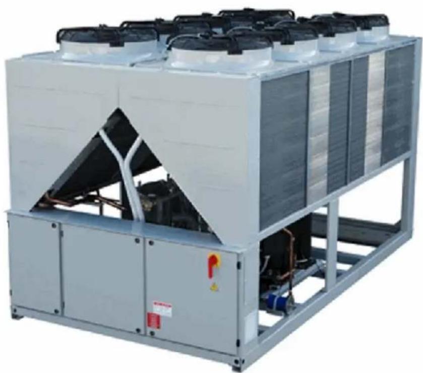
The unit you bought is an "air cooled chiller", a machine aimed to cool water (or water-glycol mixture) within the limits described in the following. The unit operation is based on vapour compression, condensation and evaporation according to reverse Carnot cycle. The main components are:
- Scroll compressor to rise the refrigerant vapour pressure from evaporation pressure to condensation pressure.
Evaporator, where the low pressure liquid refrigerant evaporates so cooling the water.
Condenser, where high pressure vapour condensate rejecting heat removed from the chilled water in the atmosphere thanks to an air cooled heat exchanger. - Expansion valve allowing to reduced the pressure of condensed liquid from condensation pressure to evaporation pressure.
General Information

All units are delivered with wiring diagrams, certified drawings, nameplate; and DOC (Declaration Of Conformity); these documents show all technical data for the unit you have bought and they MUST BE
CONSIDERED ESSENTIAL DOCUMENTS OF THIS
MANUAL
In case of any discrepancy between this manual and the equipment's documents please refer to on board documents. In case of any doubt contact the manufacturer representative. The purpose of this manual is to allow the installer and the qualified operator to ensure proper installation, commissioning and maintenance of the unit, without any risk to people, animals and/or objects.
Receiving the unit
The unit must be inspected for any possible damage immediately upon reaching final place of installation. All components described in the delivery note must be inspected and checked.
Should the unit be damaged, do not remove the damaged material and immediately report the damage to the transportation company and request they inspect the unit.
Immediately report the damage to the manufacturer representative, a set of photographs are helpful in recognizing responsibility
Damage must not be repaired before the inspection of the transportation company representative.
Before installing the unit, check that the model and power supply voltage shown on the nameplate are correct.
Responsibility for any damage after acceptance of the unit cannot be attributed to the manufacturer.
Operating limits
Storing
Environmental conditions must be within the following limits:
Minimum ambient temperature : -20°C
Maximum ambient temperature : +42°C
Maximum R.H. 95% not condensing
Storing below the minimum temperature may cause damage to components. Storing above the maximum temperature causes opening of safety valves. Storing in condensing atmosphere may damage electronic components.
Operation
Operation out of the mentioned limits may damage the unit. In case of doubts contact manufacturer representative.
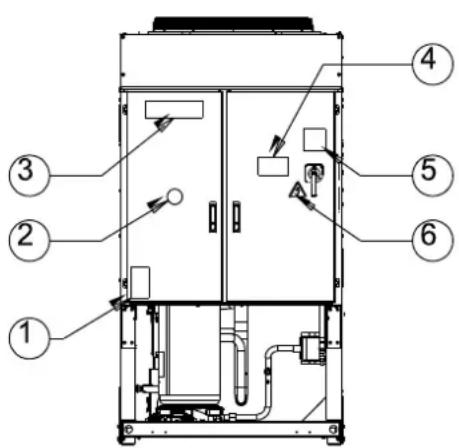
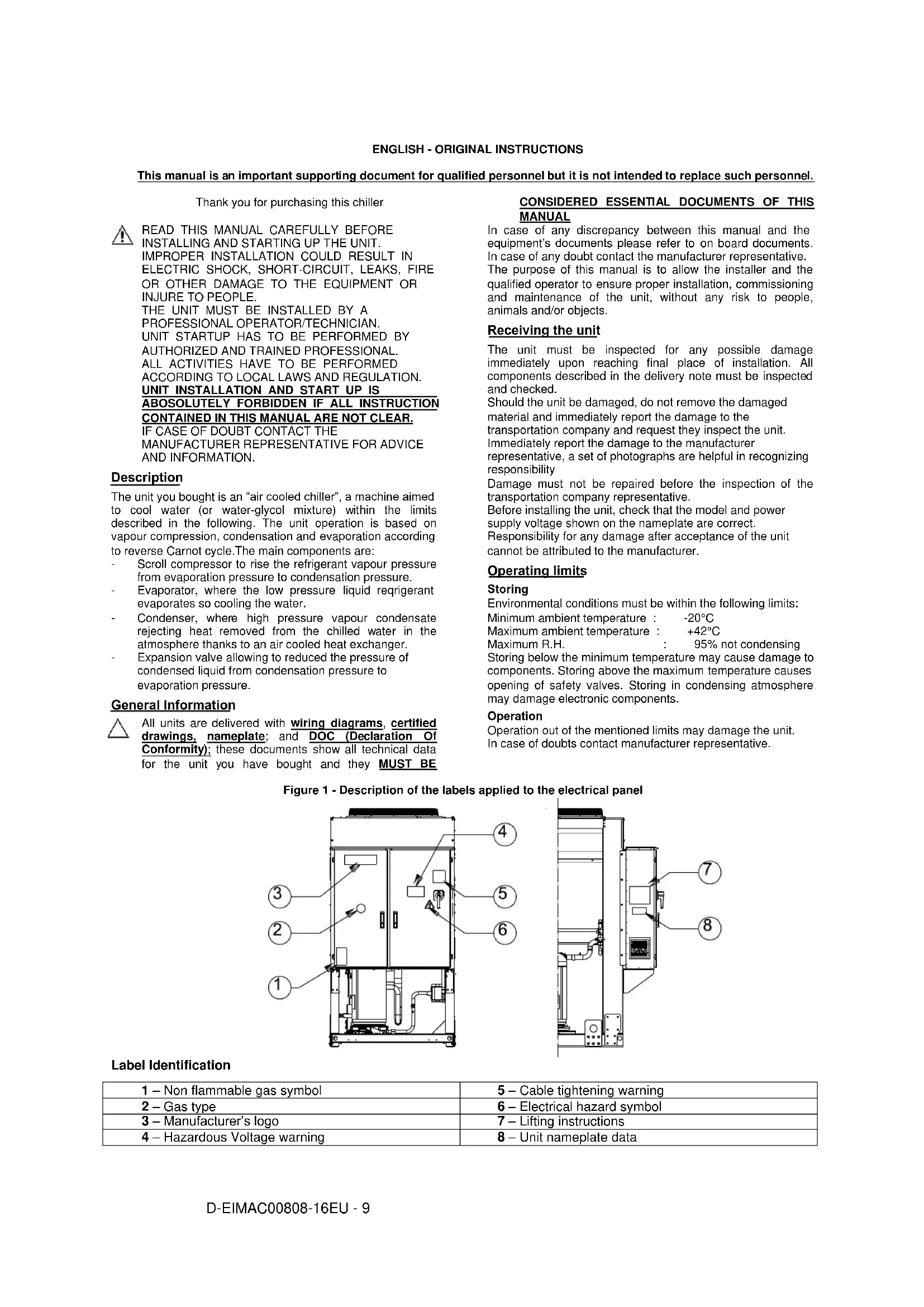
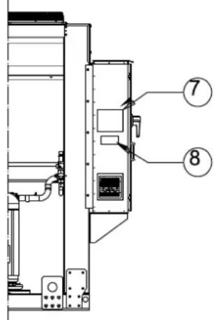
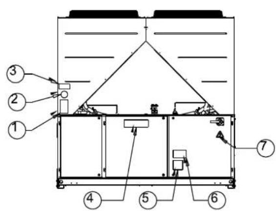
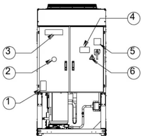
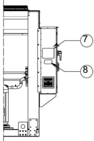
Figure 1 - Description of the labels applied to the electrical panel
Label Identification
| 1 – Non flammable gas symbol | 5 – Cable tightening warning |
| 2 – Gas type | 6 – Electrical hazard symbol |
| 3 – Manufacturer's logo | 7 – Lifting instructions |
| 4 – Hazardous Voltage warning | 8 – Unit nameplate data |
Label Identification
| 1 – Non flammable gas symbol | 5 – Cable tightening warning |
| 2 – Gas type | 6 – Hazardous Voltage warning |
| 3 – Unit nameplate data | 7 – Electrical hazard symbol |
| 4 – Manufacturer's logo | 8 – Lifting instructions |
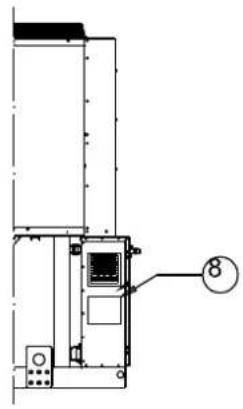
Figure 2 - Operating limits
Note
The above graphic represents a guidelines about the operating limits of the range. Please refer to Chiller Selection Software (CSS) for real operating limits working conditions for each size.
Legend
CIAT = Condenser Inlet Air Temperature (°C)
ELWT = Evaporator Leaving Water Temperature (°C)
A = Operation with Glycol (below 4^ Evap LWT)
B = Fan speed modulation or Speedtroll required (below 10^ Condens. Air Temp.)
C = Fan speed modulation or Speedtroll required (below 10^ and up to -10^ Condens. Air Temp.)
Only referred to units with 4-5-6 fans
D = In this area units can work at partial load
E = In this area the unit minimum capacity might be higher than value shown in Technical Specification table
F = Standard Efficiency (standard sound)
G = High Efficiency (standard sound)
Safety
The unit must be firmly secured to the soil.
It is essential to observe the following instructions:
- The unit can only be lifted using the lifting points marked in yellow fixed to its base.
- It is forbidden to access the electrical components without having opened the unit main switch and switched off the power supply.
- It is forbidden to access the electrical components without using an insulating platform. Do not access the electrical components if water and/or moisture are present.
- Sharp edges and the surface of the condenser section could cause injury. Avoid direct contact and use adequate protection device
- Switch off power supply, by opening the main switch, before servicing the cooling fans and/or compressors. Failure to observe this rule could result in serious personal injury.
- Do not introduce solid objects into the water pipes while the unit is connected to the system.
- A mechanical filter must be installed on the water pipe connected to the heat exchanger inlet.
- The unit is supplied with safety valves, that are installed both on the high-pressure and on the low-pressure sides of the refrigerant circuit.
It is absolutely forbidden to remove all protections of moving parts.
In case of sudden stop of the unit, follow the instructions on the Control Panel Operating Manual which is part of the onboard documentation delivered to the end user.
It is strongly recommended to perform installation and maintenance with other people. In case of accidental injury or unease, it is necessary to:
-keep calm
- press the alarm button if present in the installation site
- move the injured person in a warm place far from the unit and in rest position
- contact immediately emergency rescue personnel of the building or the Health Emergency Service
- wait without leaving the injured person alone until the rescue operators come
- give all necessary information to the rescue operators

Avoid installing the chiller in areas that could be dangerous during maintenance operations, such as platforms without parapets or railings or areas not complying with the clearance requirements around the chiller.
Noise
The unit is a source of noise mainly due to rotation of compressors and fans.
The noise level for each model size is listed in sales documentation.
If the unit is correctly installed, operated and manteined the noise emission level do not require any special protection device to operate continuously close to the unit without any risk. In case of installation with special noise requirements it could be necessary to install additional sound attenuation devices.
Moving and lifting
Avoid bumping and/or jolting during loading/unloading unit from the truck and moving it. Do not push or pull the unit from any part other than the base frame. Secure the unit inside the truck to prevent it from moving and causing damages. Do not allow any part of the unit to fall during transportation or loading/unloading.
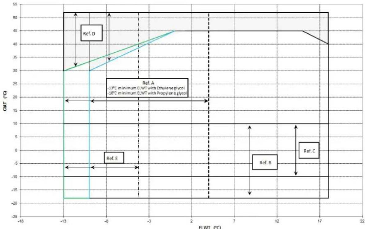
All units are supplied with the lifting points marked in yellow. Only these points may be used for lifting the unit, as shown in the following Figure 3.

Both the lifting ropes and the spacing bars must be strong enough to support the unit safely. Please check the unit's weight on the unit nameplate.
The unit must be lifted with the utmost attention and care following lifting label instructions; lift unit very slowly, keeping it perfectly level.
Positioning and assembly
All units are designed for installation outdoors, either on balconies or on the ground, provided that the installation area is free of obstacles that could reduce air flow to the condensers coil.
The unit must be installed on a robust and perfectly level foundation; should the unit be installed on balconies or roofs, it might be necessary to use weight distribution beams.
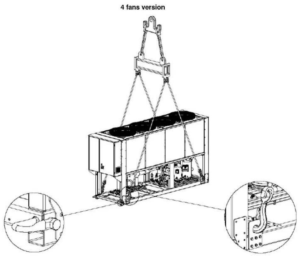
Figure 3 - Lifting the unit
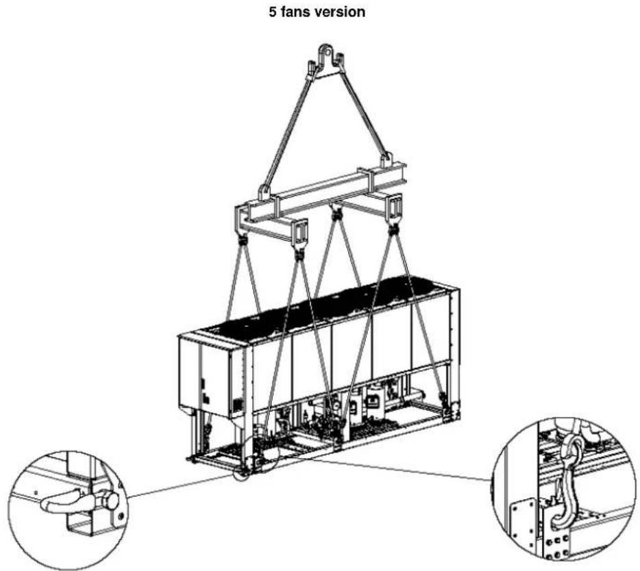
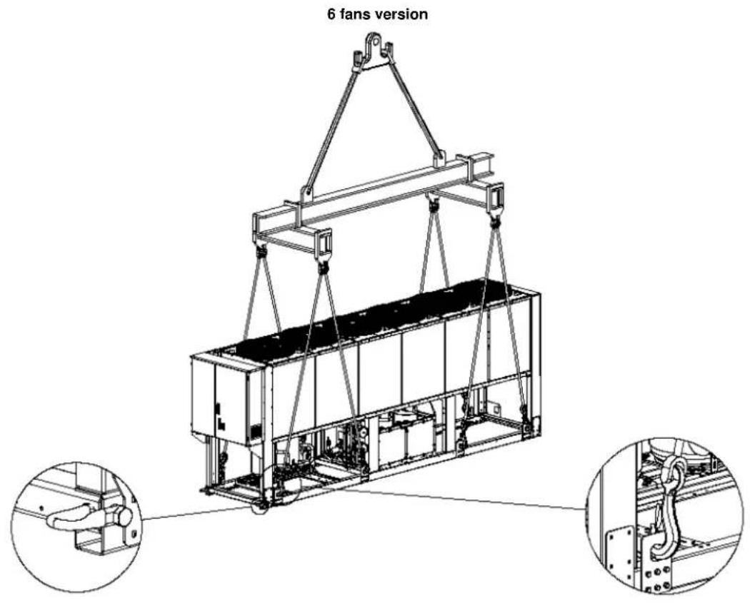
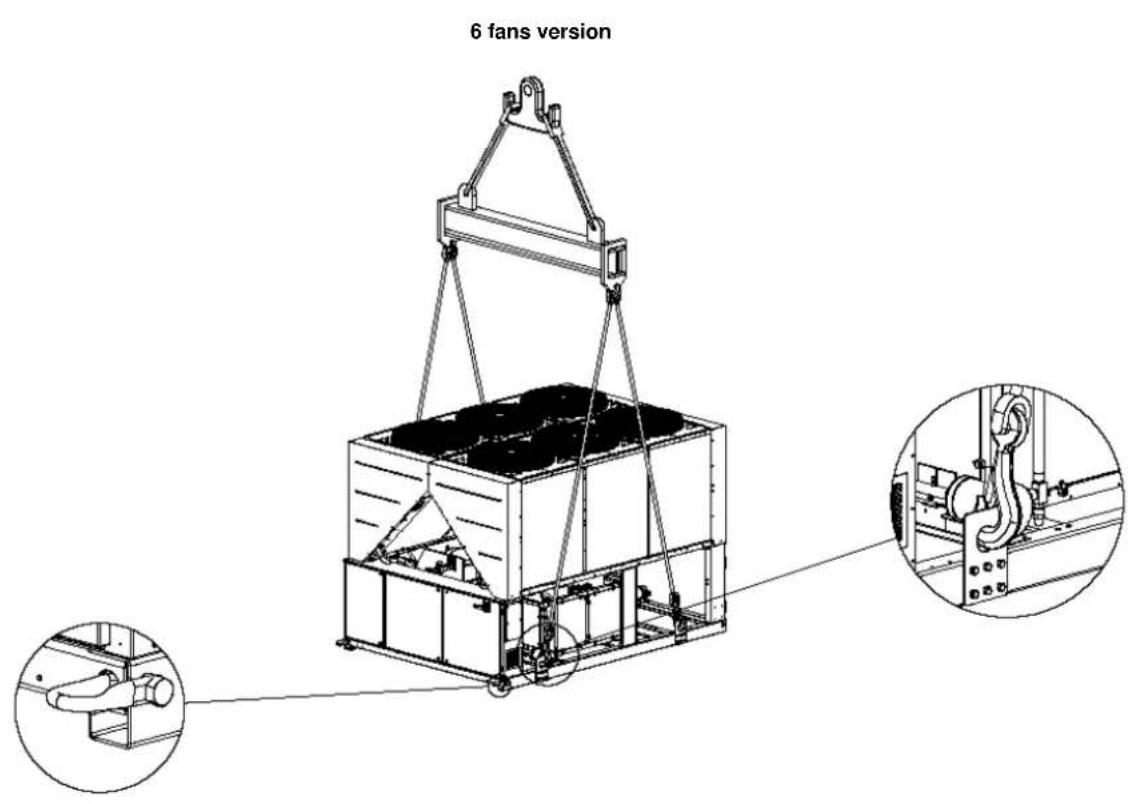
10-12 fans version
(The drawing shows only the 8 fans version. For the 10-12 fans version the lifting mode is the same)
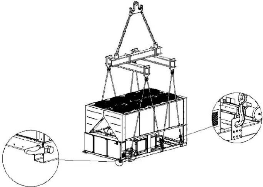
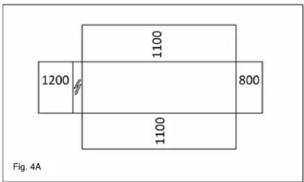
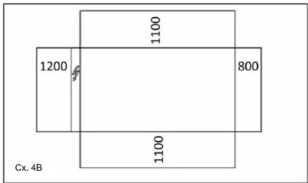
Figure 4 - Minimum clearance requirements
For installation on the ground, a strong concrete base, at least 250mm thickness and wider than the unit must be provided. This base must be able to support the weight of the unit.
If the unit is installed in places that are easily accessible to people and animals, it is advisable to install protection grids for the condenser and compressor sections.
To ensure best performance on the installation site, the following precautions and instructions must be followed:
- Avoid air flow recirculation.
- Make sure that there are no obstacles to hamper air flow.
- Make sure to provide a strong and solid foundation to reduce noise and vibrations.
- Avoid installation in particularly dusty environments, in order to reduce soiling of condensers coils.
- The water in the system must be particularly clean and all traces of oil and rust must be removed. A mechanical water filter must be installed on the unit's inlet piping.
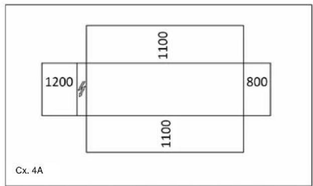
Minimum space requirements
It is fundamental to respect minimum distances on all units in order to ensure optimum ventilation to the condenser coils. When deciding where to position the unit and to ensure a proper air flow, the following factors must be taken into consideration:
- avoid any warm air recirculation
- avoid insufficient air supply to the air-cooled condenser. Both these conditions can cause an increase of condensing pressure, which leads to a reduction in energy efficiency and refrigerating capacity.
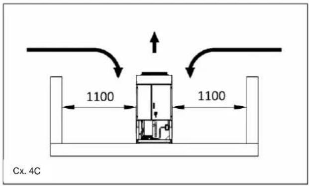
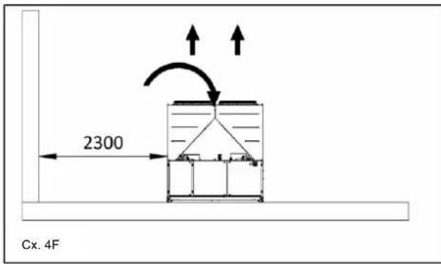
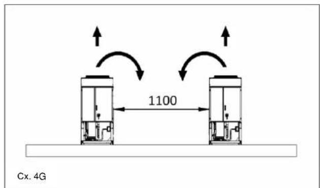
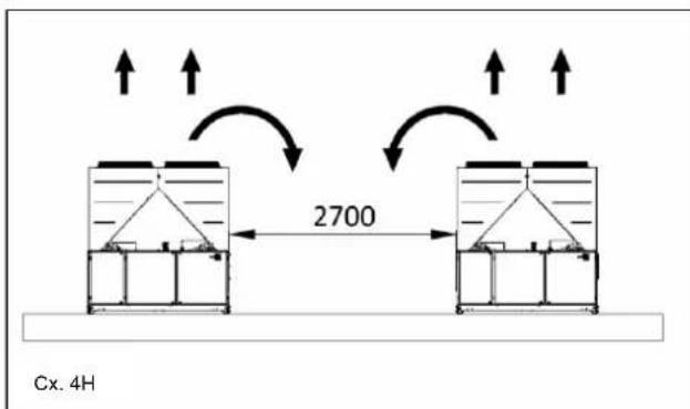
Any side of the unit must be accessible for post-installation maintenance operations. Figure 4 shows the minimum space required.
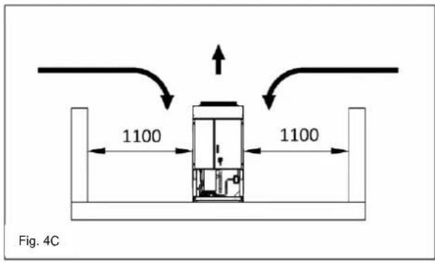
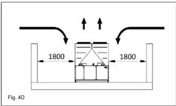
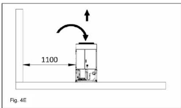
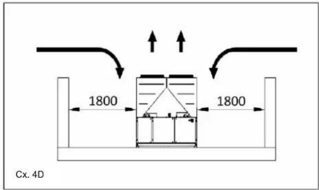
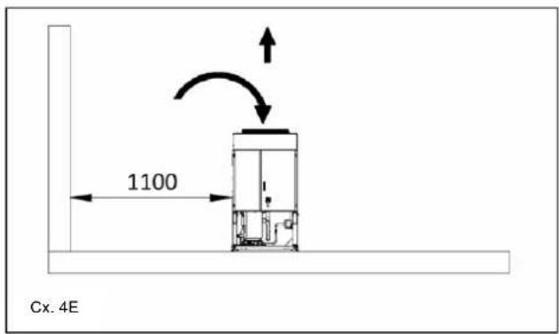
Vertical air discharge must not be obstructed. If the unit is surrounded by walls or obstacles of the same height as the unit, this must be installed at a distance no lower than (see Figure 4C or 4D). If these obstacles are higher, the unit must be installed at a distance no lower (see Figure 4E or 4F).
Should the unit be installed without observing the recommended minimum distances from walls and/or vertical obstacles, there could be a combination of warm air
recirculation and/or insufficient supply to the air-cooled condenser which could cause a reduction of capacity and efficiency.
In any case, the microprocessor will allow the unit to adapt itself to new operating conditions and deliver the maximum available capacity under any given circumstances, even if the lateral distance is lower than recommended, unless the operating conditions should affect personnel safety or unit reliability.
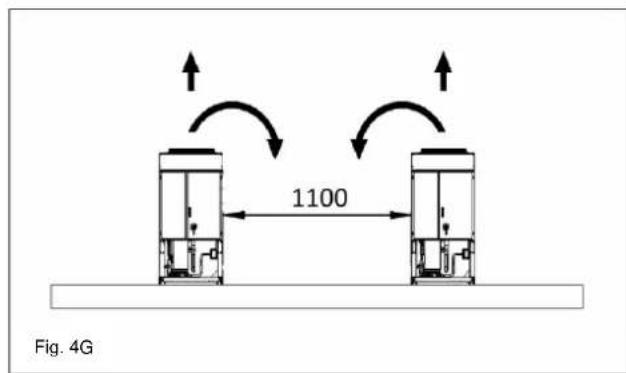
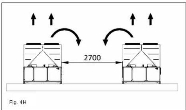
When two or more units are positioned side by side, a distance of at least (see Figure 4G or 4H) between condenser banks is recommended.
For further solutions, please consult manufacturer representative.
Sound protection
When sound levels require special control, great care must be exercised to isolate the unit from its base by appropriately applying anti-vibration elements (supplied as an option). Flexible joints must be installed on the water connections, as well.
Water piping
Piping must be designed with the lowest number of elbows and the lowest number of vertical changes of direction. In this way, installation costs are reduced considerably and system performance is improved.
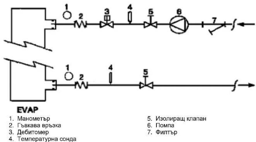
The water system must have:
1. Anti-vibration mountings in order to reduce transmission of vibrations to the structures.
2. Isolating valves to isolate the unit from the water system during service.
3. Manual or automatic air venting device at the system's highest point.; drain device at the system's lowest point.
4. Neither the evaporator nor the heat recovery device must be positioned at the system's highest point.
5. A suitable device that can maintain the water system under pressure (expansion tank, etc.).
6. Water temperature and pressure indicators to assist the operator during service and maintenance.


- A filter or device that can remove particles from the fluid. The use of a filter extends the life of the evaporator and pump and helps to keep the water system in a better condition.
- Evaporator has an electrical resistance with a thermostat that ensures protection against water freezing at ambient temperatures as low as -25^ . All the other water piping/devices outside the unit must therefore be protected against freezing.
-
The heat recovery device must be emptied of water during the winter season, unless an ethylene glycol mixture in appropriate percentage is added to the water circuit.
-
If case of unit substitution, the entire water system must be emptied and cleaned before the new unit is installed. Regular tests and proper chemical treatment of water are recommended before starting up the new unit.
- In the event that glycol is added to the water system as anti-freeze protection, pay attention to the fact that suction pressure will be lower, the unit's performance will be lower and water pressure drops will be greater. All unit-protection systems, such as anti-freeze, and low-pressure protection will need to be readjusted.
- Before insulating water piping, check that there are no leaks.
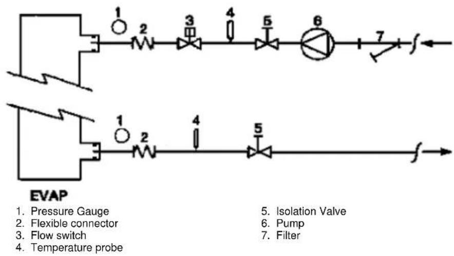
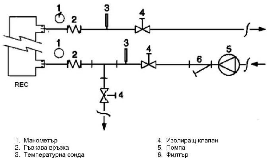
Figure 5 - Water piping connection for evaporator
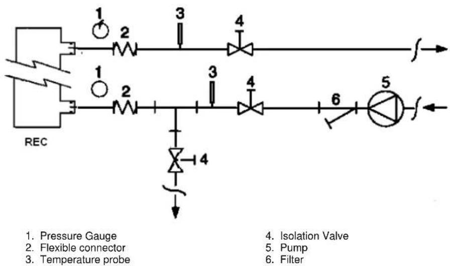
Figure 6 - Water piping connection for heat recovery exchangers
Water treatment
Before putting the unit into operation, clean the water circuit. Dirt, scales, corrosion debriets and other material can accumulate inside the heat exchanger and reduce its heat exchanging capacity. Pressure drop can increase as well, thus reducing water flow. Proper water treatment therefore reduces
the risk of corrosion, erosion, scaling, etc. The most appropriate water treatment must be determined locally, according to the type of system and water characteristics. The manufacturer is not responsible for damage to or malfunctioning of equipment caused by failure to treat water or by improperly treated water.
Table 1 - Acceptable water quality limits
| pH (25°C) | 6,8÷8,0 | Total Hardness (mg CaCO3/ l) | < 200 | |
| Electrical conductivity μS/cm (25°C) | <800 | Iron (mg Fe / l) | < 1.0 | |
| Chloride ion (mg Cl- / l) | <200 | Sulphide ion (mg S2- / l) | None | |
| Sulphate ion (mg SO42- / l) | <200 | Ammonium ion (mg NH4+ / l) | < 1.0 | |
| Alkalinity (mg CaCO3 / l) | <100 | Silica (mg SiO2 / l) | < 50 |
Evaporator and recovery exchangers anti-freeze protection
All evaporators are supplied with a thermostatically controlled anti-freeze electrical resistance, which provides adequate anti-freeze protection at temperatures as low as -25^ . However, unless the heat exchangers are completely empty and cleaned with anti-freeze solution, additional methods should also be used against freezing.
Two or more of below protection methods should be considered when designing the system as a whole:
- Continuous water flow circulation inside piping and exchangers
- Addition of an appropriate amount of glycol inside the water circuit
Additional heat insulation and heating of exposed piping - Emptying and cleaning of the heat exchanger during the winter season
It is the responsibility of the installer and/or of local maintenance personnel to ensure that described anti-freeze methods are used. Make sure that appropriate anti-freeze protection is maintained at all times. Failing to follow the instructions above could result in unit damage. Damage caused by freezing is not covered by the warranty.
Installing the flow switch
To ensure sufficient water flow through the evaporator, it is essential that a flow switch be installed on the water circuit. The flow switch can be installed either on the inlet or outlet water piping. The purpose of the flow switch is to stop the unit in the event of interrupted water flow, thus protecting the evaporator from freezing.
The manufacturer offers, as optional, a flow switch that has been selected for this purpose.
This paddle-type flow switch is suitable for heavy-duty outdoor applications (IP67) and pipe diameters in the range of 1" to 6".
The flow switch is provided with a clean contact which must be electrically connected to terminals shown in the wiring diagram.
Flow switch has to be tune to intervene when the evaporator water flow is lower than 50% of nominal flow rate.
Heat recovery
Units may be optionally equipped with heat recovery system. This system in made by a water cooled heat exchanger located on the compressors discharge pipe and a dedicated management of condensing pressure.
To guarantee compressor operation within its envelope, units with heat recovery cannot operate with water temperature of the heat recovery water lower than 28^ .
It is a responsibility of plant designer and chiller installer to guarantee the respect of this value (e.g. using recirculating bypass valve)
Electrical Installation
General specifications
All electrical connections to the unit must be carried out in compliance with laws and regulations in force. All installation, management and maintenance activities must be carried out by qualified personnel. Refer to the specific wiring diagram for the unit you have bough. Should the wiring diagram not be on the unit or should it have been lost, please contact your manufacturer representative, who will send you a copy. In case of discrepancy between wiring diagram and electrical panel/cables, please contact the manufacturer representative.
Only use copper conductors. Failure to use copper conductors could result in overheating or corrosion at connection points and could damage the unit.
To avoid interference, all control wires must be connected separately from the power cables. Use different electrical passage ducts for this purpose.
Before servicing the unit in any way, open the general disconnecting switch on the unit's main power supply. When the unit is off but the disconnecting switch is in the closed position, unused circuits are live, as well.
Never open the terminal board box of the compressors before having opened the unit's general disconnecting switch.
Contemporaneity of single-phase and three-phase loads and unbalance between phases could cause leakages towards ground up to 150mA , during the normal operation of the units of the series.
If the unit includes devices that cause superior harmonics (like VFD and phase cut), the leakage towards ground could increase to very higher values (about 2 Ampere).
The protections for the power supply system have to be designed according to the above mentioned values.
Operation
Operator's responsibilities
It is essential that the operator is appropriately trained and becomes familiar with the system before operating the unit. In addition to reading this manual, the operator must study the microprocessor operating manual and the wiring diagram in order to understand start-up sequence, operation, shutdown sequence and operation of all the safety devices.
During the unit's initial start-up phase, a technician authorized by the manufacturer is available to answer any questions and to give instructions as to the correct operating procedures.
The operator must keep a record of operating data for every installed unit. Another record should also be kept of all the periodical maintenance and servicing activities.
If the operator notes abnormal or unusual operating conditions, he is advised to consult the technical service authorized by the manufacturer.
If all power to the unit is turned off, the compressor heaters will become inoperable. Once power is resumed to the unit, the compressor and oil separator heaters must be energized a minimum of 12 hours before attempting to start the unit.
Failure to do so can damage the compressors due to excessive accumulation of liquid in the compressor.
Routine maintenance
Minimum maintenance activities are listed in Table 2
Service and limited warranty
All units are factory-tested and guaranteed for 12 months as of the first start-up or 18 months as of delivery.
These units have been developed and constructed according to high quality standards ensuring years of failure-free operation. It is important, however, to ensure proper and periodical maintenance in accordance with all the procedures listed in this manual and with good practice of machines maintenance.
We strongly advise stipulating a maintenance contract with a service authorized by the manufacturer in order to ensure efficient and problem-free service, thanks to the expertise and experience of our personnel.
It must also be taken into consideration that the unit requires maintenance also during the warranty period.
It must be borne in mind that operating the unit in an inappropriate manner, beyond its operating limits or not performing proper maintenance according to this manual can void the warranty.
Observe the following points in particular, in order to conform to warranty limits:
- The unit cannot function beyond the specified limits
- The electrical power supply must be within the voltage limits and without voltage harmonics or sudden changes.
- The three-phase power supply must not have unbalance between phases exceeding 3% . The unit must stay turned off until the electrical problem has been solved.
- No safety device, either mechanical, electrical or electronic must be disabled or overridden.
-
The water used for filling the water circuit must be clean and suitably treated. A mechanical filter must be installed at the point closest to the evaporator inlet.
-
Unless there is a specific agreement at the time of ordering, the evaporator water flow rate must never be above 120% and below 80% of the nominal flow rate.
Periodic obligatory checks and starting up of appliances under pressure
The units are included in category III of the classification established by the European Directive PED 2014/68/EU.
For chillers belonging to this category, some local regulations require a periodic inspection by an authorized agency. Please check with your local requirements.
Table 2 - Routine maintenance programme
| List of Activities | Weekly | Monthly (Note 1) | Yearly/Seas onal (Note 2) |
| General: | |||
| Reading of operating data (Note 3) | X | ||
| Visual inspection of unit for any damage and/or loosening | X | ||
| Verification of thermal insulation integrity | X | ||
| Clean and paint where necessary | X | ||
| Analysis of water (5) | X | ||
| Check of flow switch operation | X | ||
| Electrical: | |||
| Verification of control sequence | X | ||
| Verify contactor wear - Replace if necessary | X | ||
| Verify that all electrical terminals are tight - Tighten if necessary | X | ||
| Clean inside the electrical control board | X | ||
| Visual inspection of components for any signs of overheating | X | ||
| Verify operation of compressor and electrical resistance | X | ||
| Measure compressor motor insulation using the Megger | X | ||
| Refrigeration circuit: | |||
| Check for any refrigerant leakage | X | ||
| Verify refrigerant flow using the liquid sight glass - Sight glass full | X | ||
| Verify filter dryer pressure drop | X | ||
| Analyse compressor vibrations | X | ||
| Analyse compressor oil acidity (Note 6) | X | ||
| Condenser section: | |||
| Clean condenser banks (Note 4) | X | ||
| Verify that fans are well tightened | X | ||
| Verify condenser bank fins - Comb if necessary | X |
Notes:
1. Monthly activities include all the weekly ones.
2. The annual (or early season) activities include all weekly and monthly activities.
3. Unit operating values should be read on a daily basis thus keeping high observation standards.
4. In environments with a high concentration of air-borne particles, it might be necessary to clean the condenser bank more often.
5. Check for any dissolved metals.
6. TAN (Total Acid Number): ≤ 0,10: No action
Between 0.10 and 0.19 : Replace anti-acid filters and re-check after 1000 running hours. Continue to replace filters
until the TAN is lower than 0.10.
0,19 : Replace oil, oil filter and filter dryer. Verify at regular intervals.
Important information regarding the refrigerant used
This product contains fluorinated greenhouse gases. Do not vent gases into the atmosphere.
Refrigerant type: R410A
GWP(1) value: 2087,5
(1)GWP = Global Warming Potential
The refrigerant quantity necessary for standard operation is indicated on the unit name plate.
Real refrigerant quantity charged in the unit is listed on a silver sticker inside the electrical panel.
Periodical inspections for refrigerant leaks may be required depending on European or local legislation.
Please contact your local dealer for more information.
Factory and Field charged units instructions
(Important information regarding the refrigerant used)
The refrigerant system will be charged with fluorinated greenhouse gases.
Do not vent gases into the atmosphere.
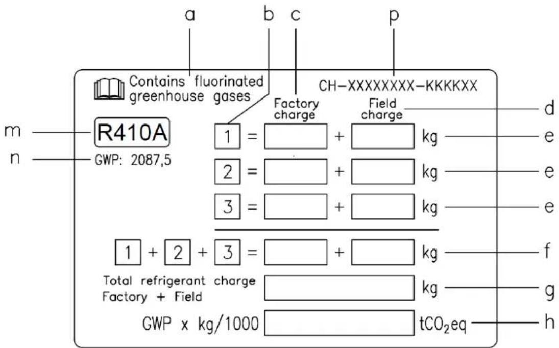
1 Fill in with indelible ink the refrigerant charge label supplied with the product as following instructions:
- the refrigerant charge for each circuit (1; 2; 3)
- the total refrigerant charge (1 + 2 + 3)
- calculate the greenhouse gas emission with the following formula:
GWP value of the refrigerant x Total refrigerant charge (in kg) / 1000
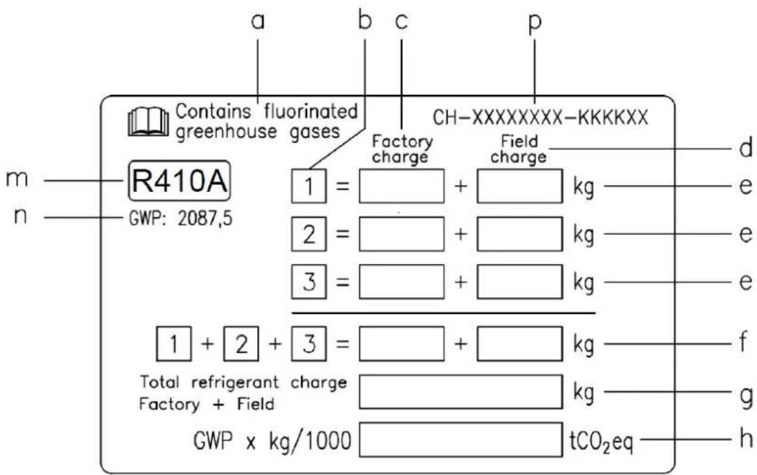
a Contains fluorinated greenhouse gases
b Circuit number
c Factory charge
d Field charge
e Refrigerant charge for each circuit (according to the number of circuits)
f Total refrigerant charge
g Total refrigerant charge (Factory + Field)
h Greenhouse gas emission of the total refrigerant charge expressed as tonnes of CO2 equivalent
m Refrigerant type
n GWP = Global Warming Potential
p Unit serial number
2 The filled out label must be adhered inside the electrical panel.
Periodical inspections for refrigerant leaks may be required depending on European or local legislation. Please contact your local dealer for more information.
NOTICE
In Europe, the greenhouse gas emission of the total refrigerant charge in the system (expressed as tonnes CO_2 equivalent) is used to determine the maintenance intervals.
Follow the applicable legislation.
Formula to calculate the greenhouse gas emission:
GWP value of the refrigerant x Total refrigerant charge (in kg) / 1000
Use the GWP value mentioned on the greenhouse gases label. This GWP value is
based on the 4th IPCC Assessment Report. The GWP value mentioned in the manual might be outdated (i.e.
based on the 3rd IPCC Assessment Report)
Disposal
The unit is made of metal, plastic and electronic parts. All these parts must be disposed of in accordance with the local regulations in terms of disposal.
Lead batteries must be collected and sent to specific refuse collection centres.
Oil must be collected and sent to specific refuse collection centres.

This manual is a technical aid and does not represent a binding offer. The content cannot be held as explicitly or implicitly guaranteed as complete, precise or reliable. All data and specifications contained herein may be modified without notice. The data communicated at the moment of the order shall hold firm. The manufacturer shall assume no liability whatsoever for any direct or indirect damage, in the widest sense of the term, ensuing from or connected with the use and/or interpretation of this manual.
We reserve the right to make changes in design and construction at any time without notice, thus the cover picture is not binding.
(1)GWP = Global Warming Potential
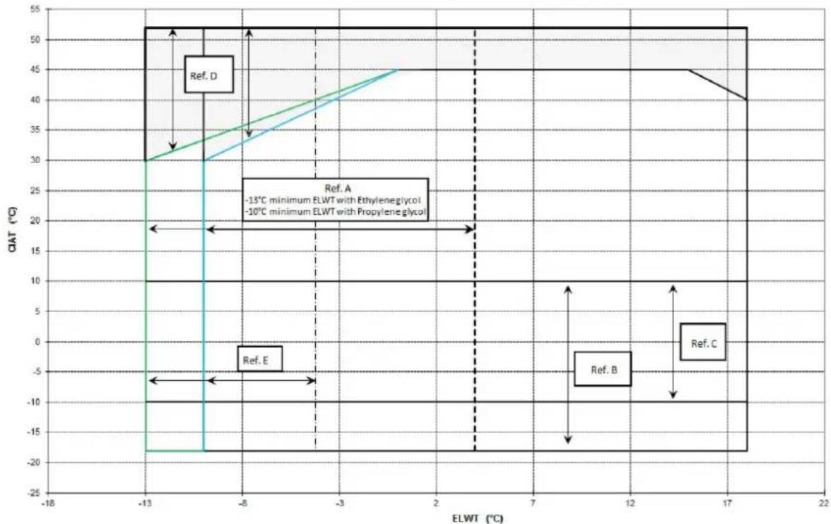
Figura 2 - Limits operatives
Nota
(1)GWP = Global Warming Potential
TtQukTe TIO OAKOUO AE CUM TY KATNYOPK, KKTIOI TOITKO KAVOWOIOTAIOTUOIOI KTEPOIKN ETEWUPON ATO JIA EQUAOBOMUEIN UTTPEO.
Iapakaiw tiopayirottoieote eayous ouipuwa ie ciattnoeis nTtepioxns oas.
NivaKas 2 - NpOypaMa TAKIKns OuvTnPnOns
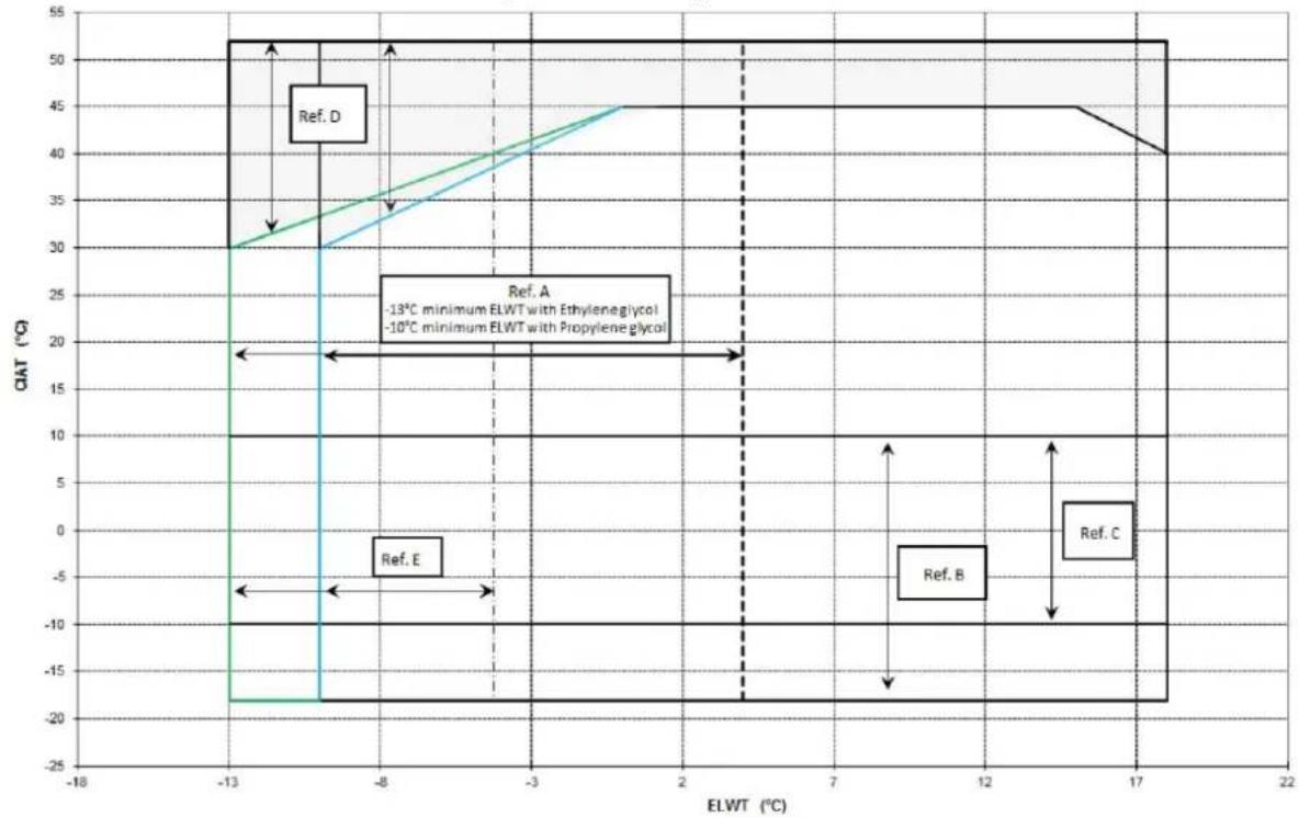
Figura 2 - Limits operatives
Nota
PemOHtheIpeaboTbNoycTpahEnHIO nobpeKHe He DoJxHbIpOBOuTBc, noka TpaHCnOpTHoe areHTCTBO He npOBEno OCMOTp.
Ipejde yem yctahOBnTB arperat y6eJntecb, 10To moenb n3neKtpueceKoe HapxkeHHe, yka3aHHoe Ha Tabnue, - npabunbHbI. N3rTOBnTeB He hecET OTBeCTBeHHOCTn 3a NobpeXdEHnHaHeCehHbI NoCne pnpema arperata.
PpeelbHbIe paobOye ycIOBn
Xpahene
YcnoBnOkpykaioeI cpebldoNkbl 6bItb npeJax Hxke yka3aHHbx napametpoB:
MIMIMaIbHaTemIepaTypaokpykaHOeIcpebl -20C
MaKmMabHbHaTEmnepaTypaOkpyKaHoueIcpebl 420
MaKcHmAbHaA OTHOHTeJIbHa BnaxHOCTb 95%6e3BvI.BaAM
XpaHeHne Pn TEmpeatype Hvcke MMHmAbbHoi MoKet PnBecTn K
NOBpeJeHIO KOMnHOHeTOB. XpaHeHne npI TemnepaType Bblue
MAKcIMaJIbHOJ MOKeT pINBecTN K OTKpbITIO ppeOxpaHHTeNbHbIX KJIanaHOB.
XpaHHe B KOHdEHCnpyIOeIcpeIe MoKTe npBecT N NOBpeKDeHHO 3JIeKTPOHHbIX KOMTOHOHTOB.
3Kcnnyataun
Arperat moKet 6bItb NcNoJIb3OBAH TOnIbKO B IpeJenax NapaMeTPOB, yka3aHHbIX Ha pnc.2.PacXoD BoIb B IcnapInTe -OT 50% Do 140% HOMHaJIbHOrO paXoJa (B CTAndApTbIX paOMyx ycNoBnx).
Pa6oTa Ipn 3naueHnIX, He COOTBeTCTBHyOuNX DaHHbIM, MoXeT IpnBecTN K NOBpeXJeHIO arperata.
PnB03HKnHOBeHHKakHX-Ni6o comHeHHO6paaIITecb K npedTabHTHO 13ROBtEJIa.
Pncyok 1 - OnncaHne 3HaKOB Ha 3NeKtpueecko nane
Onpeelenne npbIKOB
- Mahometp
- Rn6Koe rnnpabnueckoe
CoeINHeHne
3.ДачИК Temператypы
- CnB BoDbl OuNcTka TeNNoo6MeHHnKa B3MnHn nepNO.
OTBeTcBHeHocb 3a oecneueHene uIInpeOB 3auINToT OT o6MeP3aHnI
BOaIaeraTeHa MONTAKHyIO OPAHIm3aUHO WIMN MeCTbIo 06CnyKBAHOUI
nepcoHAn. PeKOMeHpyTe rne PNOIDuVEck N pOBEpTa npoBeDeHne
HaNDexKaIero 06CnyKBAHnARperata C CEJIbHO 3aUNtB ETO OT o6MeP3aHnI
HeBbINOHNHe Bblye yka3aHnOro Tpe6oBaHn MoKET nPiBcTn K
NoBPExJeHnO arperata. HeNCnpabHcOn, CB3aHHbIe C o6MeP3aHmE, He
nonadaHOT npapANTHo m3rOToBtEnra.
YcTaHOBka pene npotoKa
TtObI rapaHInpOBaTb DoCTaTOHbI npOTOK BObl K McnapTeHIO, HeoXoIMO UcTaHOBnTbepe nptOKa HbOJHM TpyobnpOBe. Pene npOTOKa MoKET 6Itb YcTAHOJIeHO Ha BXOJHM NIN BbIXOJHM TpyOBnpOBe BObl. Pene npOTOKa CnyKIn dnn OCTaHOBNk arperata B cNyae npEkpAueHn IOTOKa BObl, 3aUIma TaKIM o6Apom hncapTeJB ot O6MePAHn.
N30TOBNTbI NOCTABNtET CNEUANbHO NOIO6pAHnOe pene npoTOKa KAK ONUHO. 3To pene NIEcTKBIO TINa IpeDHAHHeHNO DnA NOCTOBHHORIO NIOBTOBBAHNI ONDOTKbIM He6OM (IP67) DnTpy6DmAMETPOM 1"O6"
Pene npotoka yKOMnIeKTOBaHO YcHbIM KOHTAKTOM IINI NOIKIOHeHNA K pa3bEaMaM, yKa3aHHbIM Ha 3neKTPnuCeCKO CXeMe.
Pene npotoka donxho 6bIb TaipnpoBaH ToKIM O6pa3OM, YTO6bl OHO cpabatbIbANO, KOJa NotOK BOJI NCTapntEn CTaHOBtBCr Mehee 50% HOMHaIbHO nponyckHO cnOco5HocTH.
PekynepaTop tenla
Ito 3anpoCy arperaTbI Mory T bItb yKomnneKToBaHbI yCTpOiCTBOM dna yTNIMSAUHN TEIIa.
3TO CHCTEMA COCTON I3 OJHORO TENNOO6MEHNKIA C BOJANBIM OXNAJDEHNEM, yCTAHOBENHHM HA CNBHNO Tpye KOJIpeccoppa, IN 3N cNeUanbHoro YCTOPCNBtA ynpABNEHN DaJIENHEMN KOJIENHCauIN.
TrobyrapaHTnpoBaTbpa0TyKOMnPecCoppaBHyTpNkoxyxA,yctpoiCTBa pekynepaun TEnJa He MoryTpa0TaTbpn Tempeatype Mehee 28°C.
OTBETCTBEHHOCb 3a c0bIOJcHMe 3TOro Tpe6OBaHM BcIaNarAeTcH NaPoeKTHIpOuBnKa O6OpyOBaHN MOnTAtXnHa KUnNepa (HAnp. McTOnb3OBaHne 6aIINaChOR KNaIanaHpeuNkUaun)
3neKtponpoBoka
O6zauHnΦopMaun

Bce 3eKtpoIOnIOKnIOUeHnArperata DoNkHbOcUyecTeBnTbCBA COOTBETCBM C DeIeCTBYOuMM 3aKOHAMn H OHPaMn.
Bce pa6bI no noKnHouEnHIO, ynpaBHeHIO nTexobcnyKBAHIO dONKbI npoBODTcKBAINnPPOBaHHm nepcoHaON.
O3nakoMbTeecb c 3nKeTpuecko cxemoi npno6peTehoro arperata. B Cnyahe OTCyTCTBIA CXEMbl NODKIOHEn Hmne e noTepri, CB8KHeTecb C MeCTbIM PnECDtBaNTeJIeM I3rTOBNTeJIa, KOTOpBI BblJlET Bam KOnIHO CXEMbl.
B cnyae HecooTBeCTBm Mekdy 3eKtpnuecko cxMoH n naHeIbO/3eJIeKTPoPBOdKO CBXHTecb C npEcdTaBntbCTBOM I3ROBOTeJIa.
IIOIOJIb3yIte TOLKBO MeHbIe IPOBQDMK, HnHe BO3MOXeH NpePpeB INN B03HKNHOBeHMe KoppoMn B MecTx CoeMHEnHMy, YTO MOxET PnVBectM K nobpeXdHnO arperata.
Bo 3660xHHe INHTpepepeHcM KabeN ynpaBneHn CnEpy npoklaDbBaTb OTeNbHOOTe NkPruecknx.C ToI cIbIO HcNOb3yIte OTeNbHbIe 3NeKTPnueckMeK KaHnJI.
Ipeep Hauanom npoBeDnna 3neKtpomOHTaxhblx paob068aTeHbHo pao3OMKHte IaBHypBbHK Ha OCHOBHM nITAHm arperata.
Ecn arperat BbKIOHcH, HO pyOBIbHc3AMKHyT, cENb HaxOHTOR noD, HanpJKeHnEM.
HnKoIa He otKpbBaIte KIeMMHyO KOp6ky KOMPpeocopOB, ecIn npedBaIepTeBHO He pa30MKNyI rnaBHy p6ynbHK arperata.
OndHbpeMeHHbe OndHoa3HaN TpExpa3HaN Harpy3K N Dc6baNaHC MeKdy
pa3aMn CTahOBraTc npMmHOyTreek Ha 3emIO ToKa Do 150 MAmnp Bo
BpEmr HopMaIbHO pa6oTb arperata.
Ecnn B coctab arperata BXOJAT yCTPOINCTBA, reHepnpyUHnne BbcUHne rapMOHnKu (Takme KAK, VFD n 3aMbKaHHe pa3b), yTeHka ToKa Ha 3emJIHO MOKet 3HaHTeNbHo YBENHtBCra (BNIOb Do 2 AMnep).
3aunita cncTeMbI 3nEeKTPoNTAHIN JOJNKA 6bITb pa3pa6OTaH B COOTBETCTBM C BBWeyNOMAryHTbM 3HaYeHMeY Te4KN.
3Kcnnyataa
OTBeTcBHeHocTh onepaTopa
Ppexd cem npctynt K kcnnytaun arperata onepatop donken npoHTn npocceohanbhyno nodrotobky u ocbotb cnctemy. Oepatop dokken BHMMaTeBHO npOHTATb daHnyu HCTpykUHIO, KpOMe TOrO, OH donken O3HAKOMITBCa NCHPTyUne no 3KcNlyataum MMKpOpnpueccOPHOR KOHTPnpeA, kYmTB CXEmbl 3NeKtPOnDkIOHEnH, YTObbl pa06paTbC B NOcNEOBaTeBHOCTaIpyCKa, pAOToB, OCTAHOBKn arperata N O3HAKOMITBCO BCEMy UCTPOINCTBAMN 6eONaCHOCTN.
Bo Bpem NepBoro 3anycka arperata DOJnxHe pncyTcBOBaTb TexHmecKn, yNtOHMOeHHbN H3rTOBtTeHem CnueuAInCT, KOTOpb MOKeT OTBeTb Ha Bo3NHKAoUne npn 3anycke BONpOcbI NaTaB peKOMeHaUNn No npabINbHO3KnpyaTaunn arperata.
Onepatop DOnJKeH BecTH 3aNcN TExNHIO-KcNpyTaUHOHBIX DaHHbIX KaKdOrO yCTaHOBHeHHoro arperata. TaKe DoXHbI BecTNC b3aNcN O npoBeeHNm nepNOuYeCKOrO cepBcHOrO Tex6cbyKmbAHn.
Ecnn onepatop 3aemaeet Henoiaikn B pa6ote aperata, OH donkeh o6paTbCBABTOIN3OBaHHy CEPBNCHy CnyKbI N3OTOBITEJI.
I Pn BkIOeHOM arpeTe HeB0MOXHO HcNOb3ObaTb OBorpeBaTeN B KOMPecoppa. Nocne NocoeDHeHnARperape Ta 3eKtpOniTaHIO OCTabTe OOBorpeBATEH NOMPecoppa IOTdENHTeMaCna dNRAZAPdKN KAK MNHMMy HA 12 cAcOB, INTOBko Nocne 3TOrO 3AnyCTMe arperat.
Hec6nIeHne3ToHOpMbMoKETPmBecTKNIOBpeKeHHoKOMnPceccopOB CBA3N Cype3MebpHbIM HAKONJIeHMeM XIKKOCTMHBYTPn HNX.
PernamEnHIOBaaHHbIe pa60TbI no cepBnCHOMy 06cnyKBAHmO
Heo6xqDmblpepa0bI no cepBmChomy 6cbnykmbaHnno nepeHncIeHb B Ta6nla2.
CepBnchoe n rapaHTmHoe 06cJyKbBaHne
Bce arperatb npoxoJt nCbtaHnHa Ha 3aBoe n NOnyauHOT rapaHTIO 12 MecaeB OT nepBoro 3aYcKa nn 18 MecaeB OT MOMeTa NOCTABKn.
3n arperatb6bln pa3pa0tahbln cKoHCTpynpobAHbIc yyTOM HauMblicux HAueCTbeHHbX CTaHdaptOB C zebblno rapaHTN nnlntelbHoro cpoKa cnYkb6 Be3 HenoLaoK. Tem He meNe, oeHb BaxHo npOboNTB npnoDneckoe TexoCpynkmbAHBe B COOTBECTBm C npOeUdpamYkaahHBMIN B daHHO INCHTPKIMN n C 6Oble pnnHToTn pApTKIO OcCnykmbAHn OBOpYDOBAHn.
Y6eHTeBnO peKOMeHnyEm 3akHOnHb Dorobop TExo6cnyBaHm C yIOTHOHcHbIM cepBbHbM CEHTPOM KTOBOITeR N C cEIOHOraHTN M cFpEKTHOBEOcePnp6bNmHO eOpBCHORO 06cnyBaHn, BnAorapr ObyT n KOMETEHCTNO hawero nepcoHana.
Kpome toro, Heo6xOIMO yHtBbAtb, YTO arperat donKeH noDBepraTbcn nepmoDueckomy 06cnykBaHIO taKae B TeHeMe rapaTmHoro nepnoa.
PpIMMTE K CBeDEHINIO, YTO HenPaBnIbHoe NcOJIb3oBaHne arperaTa, HApIMep C npBbIeHHeM pa6OuHX Bo3MOXHOCTeN INN 5E3 npOBeDHeN O6ClyKWBAHN B COOTBECTBm C yka3AHmM DAHHORO pyKOBoDCTBA, He NOKpbBAeTCra rapaHTNe. RapAHTNocCTaTeC TdEHTBteLbHO npCobIOHeHn CNEyOuNX Tpe6oBaHm:
- HeIb3a BbIXoDmTb 3a yKa3aHaHbIe 3KcNjyataLIOHHbIe npedeBbI arperata
- 3NeekTpuHecKoe nTaHHe DOnJHo COOTBcTcBOBaTb Tpe6yEmomy HapRaeHHo 6e rapMOHNu BHe3aNbIX NepenadOB HapRaeHHn.
- Dicapanacp 3pxePbA0BORI nTnAHA He IOnKHe npBbHAtb 3 % Arpcat OIOKeO octabcB BkIOHHeBIM, NOA He 6ydet BCocTaOHBeHa JKeTPrMecKa HENoJaKa.
4.HeOTKIOHaeIte HneOTMeHaeTHe NQHO MEXAHHEeCKHX, 3NEKTPnueckHX INN 3NEKTPoHHbIX yCTpoCTB 6eONaCHOCTH.
5.Boa,NCIOJIb3yEmaB INIpaBnueckOM KOHType,DOJINKa 6bItb YICCTOIN I npaBnIbHO 6bpa5oTaHHo.Kak MoXHo 6bnKe KO BXOy B INCnapntJIb DoJxKeH 6bItb yCTaHOBJeMexAHueckmФInTp. - PacxO B0dyB CnapmTene He DoJIxH NpeBbIaTb 120% H6Itb Hxke 80% OT HOMHaJIbHOrO pacxOda,3a NCKJIIOUeHHeM OTINuHO KOHKpeTHOH DOROBOpEHNOCTHa MoMeHT 3aKa3a.
O6a3aTeIbHbIe nepNoDmUeCKne npOBepKn 3aynck ycTpoiCTB, pa6oTaIOxN NOd DaBNeHHeM
ArperatbOthocraK III KateropnKnaccKaun cornaHcEbponeckoM npekTbePED2014/68/EU.
D-EIMAC00808-16EU-113
HeKOTOpBHe MeCTHbIe HOpMaTnBbI npeyCMaTpNBAOT nepoMDuecky npOBepKy YINNEPOB DaHHNo KaTeOpMn CO CTOpOHy yONHOOMOeHHbIX aRETCB.
IpoBepbTe, KaKHe TpeoBaHm DeCTByHOT Ha MeCeYcTaHOBKM.
Ta6nua2-ΓpaΦnk npoBeDeHnpeTnAmeHTbIX pa60T
DahHoe n3dJIne coOpKHT TOpupoBaHHbIe CoeINHeHn. He donyckaTe nx BbIbPOca B aTMocpepy.
TnXnaaareHtA: R410A
BelenuHaPiPi(1): 2087,5
1)πn:
TnHnann noabnbno notenneHn
KoIueCTBO xIaIareHTA, Heo6xOmmoro Ira cTaHapTHOH 3KcTnyatauIM, yka3bBaETcHa NaacnOpTHo TaBnUke arperata.
PealbHoe KOniueCTBO XnadareHTa Barperate Yka3aHO Ha cepepbHO HA KeIeKHe BHyTpI 3NeKtpuecko nHaHeIM.
B 3aBcIMOCnO t TpeBaHm Ebponeckoro nI MecTHoro 3aKoHdaTeJIbCTBa MoKet Bc3HMKHyTb Heo6xOIMOCt PbepOuHnecko IpoBepKn Ha npedMet
06HApyKeHH yTeueK xHaDareHTa.
Дяболп подрбов Информанno ДаднOMY BONPOCY CBKINTeCb C MeCTHBIM TOPROBIM aReHTOM.
Hnctpykncn no o6paueHIO c arperaTAM, 3apxkeHHbIMn Ha 3aBOde n Ha o6beKeTe
(BaXnHnVHΦOpMaunOTHOCHTeBHO NcNtB3yEmoTO XnaDareHTa)
CnCTema xnaadareHTa 6yET 3apxkeHa fTOpnpoBaHHbIMn npHnKOBbIMn r3amN.
He donyckatb BbIbpoca ra3OB bAtmocpepy.
1 NcnoB3yHeCMBIbAeMbIe UepHnla, 3aNoHNbTb 3TNKeTKy 3apJaXnaIaIaREHTa B COOTBeTCTBm CO CneDyUoSei HNCTpyKUnei:
- yka3aTb 3apd xnaadareHt dnn KaKdoRo KOHTya (1;2;3);
- yka3aTb 6uui 3apx xnaDarEHTa (1 + 2 + 3).
- BBHNCINb Bb6pocbI napHKOBbIX ra3OB no φopmyne: 3aueHnE IITX xlaareHTa x obuN 3apd XlaareHTa (B KInorpaMm) / 1000
a PnpCyTCTBnE @TopuPoBaHHbIX napHkoBbIX ra3OB
bHomep kOHTypa
c 3aBOdcko3ap
d 3apn Ha oBekTe
e 3apxnaaareHt aKkdoRo KOHTypa (B COOTBETCTBnC CYNCIM KOHTypOB)
f O6u3apx xlaaareHa
g O6u3apn XnaaReHTa (3apn Ha 3aOBe + 3apn Ha o6bKeTe)
h Bb6pocbI npHnKOBbIX ra30B nIaO mbero 3apra XnaDareHTa, BblpaXeHHbIE B TOHHAX B nepeCye Ta CO2
m Tyn xnaadareHta
n GWP = noteHuaan rnoBaabHoro noTepeHna (Pi)
p CepnHbH Homep arperata
23anolneHHyio 3TNKeTky npKNeIb BHyTp nEKeTpueckoro uHaTa.
Corlacho ebPoneckomy Hn MeTHOMy 3aKoHOnaTeNbCTBy, Ha 3OT arperat MoryT pacnpocpaHrTBcra Tpe6obAHnO nepnoDnueckon npOBepke Ha OTCyTCTBne yTeeK xnaIaReHTa. DOnONHInTehHyIO INOpMaunHO MOXHO NOLYHTb y MeCTHO DnJIepa.

PIMMEYAHNE
3NaueHne Bb6pocOB napHkoBbIX ra3OB, 3aBnCJee OE O6Iero 3apJa xJaIaReHTa B CnCTeMe
N BbipaxKaemoe B ToHHax B nepeCyeTe Ha CO 2, nCNoB3yeTcB Ebpone npn OnpeDeneHn INHePbaIOB
TexHueCKOrO o6CnyKuBaHn.
Co6nDaTb npmEHMbIe 3aKoHOdaTeIbHbIe HOpMbI.
ΦopMynaДЯВbIYncJIeHnBbIbPoCoB napHKnOBbIXra3OB: 3NaueHne IITXnaIaReHTa xO6uN 3apJxnaIaReHTa (B KINorpaMMax) /1000
Heo6xOIMo NcNoIb30BaTb 3aueHHe NII, yka3aHHoe Ha 3tNKeTke npHkoBbIX rA3OB. DaHHoe 3aueHne IINnOlyeHO Ha OCHOB MaTePnAnOB 4- ro 3KcpepTHoro OTeTa MekKnpaBntbCTBeHHo KOMnCCm No n3MeHeHIO KInMaTA. Yka3aHHoe B pyKobODCTBe 3aueHHe NII MoKet OKa3aTbCBy cTapeBUnM (HaNPmep, nOlyeHHbIM Ha OCHOB MaTePnAnOB 3- ro 3KcpepTHoro OTeTa MekKnpaBntbCTBeHHo KOMnCCm No n3MeHeHIO KInMaTa).
YTNIN3aun
Arperat 3roToBneH 3 MetaIInHeckxN, nactMaccoBix N 3eKtpoHHbIX KOMIOHeTob. Bce KOMIOHeHTbl DOnXHbI 6bITb yTNIN3nPoBaHbI B COOTBeCTBm C MeCTbIMM DeCTByOuMMn npabunamn.
CBNIOBBIEAkkmyIATOpbI DOnJXHbI yTNIM3MPOBaTcBcO TDeJIbHO IOTnpaBnTbcB CneUInaBHe ueHTpbl c0pa oTxOIOB.
Macno Heo6xOIMO yTuIN3npoBaTb OTdJIbHO nOTnpAIBTb CneUaIbHbIe CEHTpbI c6opa OTxOIOB.
Dahnoe pykOBoCTBO npOctAaBnE TEXHcKyo NOdepKy Hn RnreTc OBbBAHOHm npDIOXHEHM. HeB3n PnMbIM INN KOCBEHbIM oBaPOMRAPHTPOBAtb, nTO pyNOBCTBO coepKIn NoHtY, ToHy, BepHy INHcOpMaHb. Bc NHCOPMAu IN TEXHcNEe daHbIe, cOepKaUeCe B pyKObCTBe, MOryt bItb N3MeHeHb 6e3 npdypeKdHn. NHCOPMaH, nepaeha HA MoMeT 3Aka3a, CHtaETAc HEMMeHHoH.
H3TOBMTHe He HecET OTBeTcBEHHOCTH 3a pMHNHEHMe pPmoro HnN KocBHeHOro BpeDa, B WpOKOM CbKne 3ToI CNObA, 3aHcraero HnN CB3AHHO r c HcnoIb3OBAHem WnHn TpaKTOBkON daHHORo pyKOBOCTBa.
OCTABINEM 3a c06oPiabaBnCnCTpykTbHbIe N CTPyKtypHbIe IMaMeHHe B aIperat B IIObOMoment Be3 npDynpEckHeN. CnepOBateBbHO, H3oPaxKe He OboKke He RaBnTeC
(1)GWP = Global Warming Potential
(Global potensiell oppvarming)
(1)GWP = Global Warming Potential
(1)GWP = Global Warming
Potential (Potencijal Globalnog
Zatopljenja)
Kolicina potrebnog rashladnog sredstva potrebnog za standardne operacije se navodi na natpisnoj ploci uredaja.
Stvarna količina unesenog rashladnog sredstva u urežaj se navodi na srebrnoj naljepnici u unutrašnjosti elektrène poče.
Periodicna inspekcija curenja rashladnog sredstva moze biti potrebna s obzirom na Europske ili lokalne propise.
Molimo Vas dakontaktirate vaseg lokalnog zastupnika radi dodatnih informacija.
Upute o tvornickom punjenju jedinica i punjenju na terenu
He Tp6Ba Da mHa np6Bemn 3a N3BbpuBaHe Ha BepTmKaHOr OTBeXdaHe.
Korato ypeBt e orpaedH OT cTeHN mnn npeMeTn, cbc cbuata BnuCOnHa KaTo Ta3n Ha ypeDa, ToT Tp86Ba Da ce MOHTnpa Ha pactoHHe No-MaNko OT (BvKTe Cxema 4C mnn 4D). Korato npEeMetne ca no- 6. BucOKn, ypeBt Tpr86Ba da ce MOHTnpa Ha pactoHHe He No-MaNko OT (BvKTe Cxema 4E mnn 4F).
Korato ypeBt ce MOHTnpa 63 da ce cna3BAT MNHIMANHITne npenOpbYbaHn paTcOHHa 3a CTeHNTe N/INBepTKaHn PpeDMTe,MOKeJa de COnyUH KOMBUNAUMoT oPEuKNIPaHe Ha TOTbl Bb3DyX
BodonpoBOnHa cnCTema Tp8Ba da pa3noIaracbC:
- MoHTpaHa Ha aHTMnB6pAtOpn 3a HamaTnBaHe Ha npedBaHe Ha Bn6paunTe Ha KOHCTpyKUmaTa.
- 130mpaun KIanaHn 3a HzmpaHe Ha ypeDa OT BODonpoBOnHata
cnCTema, No Bpeme Ha onepaunite No o6cnykBaHe. - PmncIOOCbEHNTo 3a OeEBbAduBaHa He pbKa n ABTomAtHHo
Ha Hau-BnCOKATA TOKA Ha ONCTema, aypeDa 3a OTBeKdaB HnHnCKaTATOyKa. - V3oIaTOpBtN npMOnocObeHme 3a TOnmHHa eHepnV He Tp6Ba da ca pa3nIOXeHb HbHbCOKata TOHk HA OCTemata.
- PdOxopDnO npncIOoBHeHne, KoTo Da MoKe Da NpOdbPka BOOpnpOBODHaTcNCTema NoD HAnraHe (pa3wnpuTeJeH cbn
6.Индikatopma3a HanraHaeN TemnepatpaHa BOData,KOITO cnykar Ha onepatop,a no Bpeme Ha onepaunite no obcnykbae Hn ondpbxka.
Cxema4-И3nckBaHna 3a MmHmamHo paCToHHe
7.ФИNTbP ININ pnpCnOcO6JIeHHe 3a OTcTpaHraBaHe Ha YAcTHIuTeOT TeHIOCTTa.N3NoJ3BAHeTO HFaNITbYdJbXkaba XKBOtaHa N3oJAtopaH Na NOMNaT, KaTo NOMara 3a NoDlbpKaHa He BODOnPoBOdHaTcCTMeA B NO-Do6Po CbCTOrHHe.
8.ИЗолатура Има eнктпческ CBnpOTNBLNeHne C TePmocTa,OCIpyraBa 3aUnTc PceUy 3aMpb3BaHe H BODaT npINMHIMJIHa TemnepaTy Ha CpeDAt O T-25°C.BcnKn DpyrTp6bN 3a BODa/BbHUnBODOpOBDoH pncnocO6JIeHn KbMypeDa,Tp8Ba Da 6bDat3aUnTeHn O T3aMpb3BaHe.
9. Pnncoc6neHHeTo 3a TonnnnHa eHepnra Tpr6Ba Da ce n3npa3HN OT BODATA, NO BpEMe Ha 3mmHnT Ce3OH, OCBEN B Cnyuante KORATO KbM He 6De DoabaeHa Cmec OT ETNIOB IINKoI, B CbOTBEHTOPOeHTHO CbOTHOseHHe.
- Pn CMHa Ha ypea, pnaTb Odo npobOda nCTema Tp6Ba da ce n3npa3Hn NOnCHtN ppei NHCtANPnape Ha HOB ypeD. Ppei NpyckaHa HOBnT ypeD, ce npenOpbYBa, N8BbPbBaHe Ha 06buaHn TcTeOBe NPOXdoJnN ObpaBKn HA BOData.
11.Пи дбавгHe Ha mknKbM BODnpoBdHata CNTema KaTO 3aunTa OT 3aMp3BaHe,ObpHTe BnHaMaHne,HanraHTo Ha 3aCMyKBaHe DA 6bJe NO-HNcKO,XapakTePncTHKnTE Ha ypeDa ca NO-LOuN cnaIOBeT B HanaRaHTo Ca no-roEmN.BCnHm CNTeM 3aauTa HA ypeDa,KATO Ta3N OT 3aMp3BaHe,N 3aunTa OT HNCO HANrAHe,TP8Ba OTHOBa Da 6bDat HactpoEHN. - IpeHnI3OIIpaHe Ha BOHNITe Tpb6n, IpoBepTe 3a TEHOBe.
Cxema5-Cbbp3BaHeHa Tpb6nte 3a B0da KbM n3napnten
Cxema6-CBbp3BaHeHa Tpb6nTe 3a B0da 3a Tonnoo6MeHHnTe 3a TonnnHna eheprna
06pa60ka Ha BodaTa
Ipein 3aenCTBaHe Ha ypeHa, noocTeTe BODHnT KpbT. 3AmbpcBaHHBapOBHK,HacnARBaHHO T KOPO3N ININ Dpyr MATEpHAn, MORa Da ce HATpynAT OTBbTpHe HA TOONIO6MeHHnKa N da HAMaJIrKanAunTeTbT My 3a TOnIIHNHe 06mH. MoKe Da ce yBeJInu n Cnada B HANraHETo, KOeTO HAMaJIraNoTOKa Ha BOdTa. IOnXoJaUta Opa6oTKa Ha BOdTa,MOKe Da HAMaJIn OnaCHOCTTa OT KOPO3N, EPO3N,
06pa3yBaHe HbBfIepoN dpyr. Han-noDxOJaunT haHn 3a 06pa6Oka Ha BOdaT, Tp8Ba Da 6bJe onepdienHa MRCTo, B 3aBNCIMOCT OT Bua Ha CnCTeMaT a O T XapaKTePcNTknte Ha BOdaT.
Ipon3bOndTeHHeoNOTROBOPHOCT3aBb3MOXHNJETNI IIO naP0aGoTAHaypeDa,BCNeDCTBnE HaEN3BbPSeHaNN HEnpauNHaOpa6OToKA HA BOdTa.
Ta6nua1-OnyctmHrpaHn3aKaueCTbToHaBodaTa
| pH (25°C) KMSEINIHHOCCT | 6,8÷8,0 | ОБся Тьрдост (mg CaCO3 / l) | < 200 | |
| Енекгichtecke пюворимост μS/cm (25°C) | <800 | Желаязо (mg Fe / l) | < 1,0 | |
| Хлорадийони (mg Cl- / l) | <200 | Сулфандийони (mg S- / l) | Няма | |
| Сулфандийони (mg SO4- / l) | <200 | Аmonіевийони (mg NH4+ / l) | < 1,0 | |
| Акалноct (mg CaCO3 / l) | <100 | Силицhev діожcodи (mg SiO2 / l) | < 50 |
3aunita npotnb 3ampb3BaHe Ha o6MeHHn3n 3a tonnnnHa eHepnna H3oJatop
Bcnn H3oJatopn ca Ch6deHc eNeKtpueecko CbnpotnBHeHne, TepMocTaTnHpo perynpaHc, KoTo OcnrypBa NoDxoJaTa 3aUHTa npo 3ampb3aHaepnn MMmMaHn TEMpePAtypn OT-25°C. He3abmcmoT TOBA,
10OCBEN KORA TO TNOO6MeHHNtIe Ca HnTbNHO nPn3HN N NOUCTEH C p 2. I npOTNB 3aMpb3BaHe, MOrA Te Da ce H3NON3BaT N DOnbNHTeHNI MeN pNPOTNB 3aMpb3BaHe.
Pn npoeKtnpaHe Ha CNTeMaTa KaTo UaNo, Ce IMaT PpeBnD Dba MeT 3aunTa, ONNCAnH No-Dony:
IIOCTOHHO UINPKyNIPAHe HA BOJEN NOToK OTBbTpE Ha Tpb6nTe HAnTOIIIOoMeHHnTe
-Добаяне Ha noDxOJaIPO KOnIYeCTBO rIINKoI OTBbTpE Ha BOHnIaT KpbI.
TonnHn HAonlaHn n DOnbHnTeHn OtonneHa HnOKeHmTe Tpb6n
- IV3npa3BaHe I NOuInCTBaHe Ha TOnIIOo6MeHHnka No BpeMe Ha 3IMHncaC83OH
OTROBOPHOCT Ha HNCTaHINPAUHT N/IN HA MeCTHNT NEPCOHAN NO. NOIDpbKKa, e da OCNpyn N3NOIN3BAHETo HA METOIN pNOT 3aMpb3BaH INPOBepete Daan Ce npinarat peOBHO NOxODyu ONEpaunn, no NOIDpbKKa 3a 3auTn APOTN 3aMpb3BaHe. Hecna3BaHoTo Ha yka3aHn POtope, MoeJa NoBpeDypeDa NpBpeDte BcNDCTBHe Ha 3aMpb3BaHe He ca NOKPITN OT RAPAHUHTA.
MOHTIPAHe Ha De6bntOmeP
3a OcNrypBaHe Ha DoCTaBChEN NOTOK Ha BODaTa B CEINrT N3OAnBaBaxHO Da Ce MOHTIpe De6bITOMep BbB BODONPBOBDHNRT KpbT, KOITMOCe NoCTABn Ha BODHnTE TpbNnHa BxOJa INn HxOJa. De6bITOMepBb3A cInpaHe HA YpeDa, B CnyuAh Na PneKcBAeHa NOtOKa Ha BOpeNpEa3BaMnNo TO3n HauHH N3OAnTopo AT 3Ampb3BaHe.
PpOIN3BOIDNTeIaT npeIana, KaTO onuN, De6HTOMep noxOJaU 3a npINOJKeHne.
To3n De6ntomep BnI JbXnUka, e NoDxOJa 3a NoCToHHN npHIO HABH (IP67),cDnAmetbpHaTpbMeTeOT "do6."
IeBHTpePnTcHCTKIOTO TpBaDa ce CbPHe eNekTPnuCeKn KbM TepMNHaJIte, Yka3aHn Ha eneKTpuYeckaTa cXema.
1 De6bntOmept Tp8a Da ce kainbnpa, 3a da Moxe da ce n3BbpuH H pni cna Ha notoka Ha BodaT noDaBaHa Ha n3oNaTopa npd 50% paobToTHKanauTet.
OTdabaHe Ha ToTnHHa eHeprna
IIO JENAHNE, YpeBt MOKeJa 6bJe CHa6DeH, Cbc CnCTema 3a OTDaBA TOPNIHHA eHePnI.
Ta3n CnCTema Ce NOCTABRA 3aEHNo C TOnJIOOMeHHNK, C BoNDHO OXlaJaDa OTBExKaDaaTAt Ptb6a Ha KOMnPecopa, H Ha pNcNOC6JeHHeTo 3a NODxOyU npAbaHHe Ha HAJIraHaTe H KOHD3InPaHe.
3a OCMYPRABaHe pa6oTata Ha KOMNpeCopa, OTbBtpe Ha HerOBnT HypeBt 3a TonPINHHa eHeprna, He MoKe Da pa6oTn npn TemnepaTpa HbObaTata noD 28^
PoeKtnpuaHHT HCTanpaHtna HnCTanatopbTa HoxnAdTnH,HOaT OTTOBOPHoc3a CnBaHe Ha Ta3n CTOnHocT (HaNP. c NoctabRe Ha KNa peUKNIPAe BND bypass).
EneKtpuecka nHctanaucn
06uN3nCKBaHn
BcNk eIeKtpueeKn Bp3kn Ha ypeA, Tp86Ba da ce n3nblnHr CbOTBeTCTBNE, C deIeTBaUNTE 3aKOH N HOpMaTNB. BcNk DeHoctn No MoTAn, YnpabNeHne N noDp8kKa Tp86Ba ce n3bPbWbAT OT KbanuФuupan nepcohan.
Hanpabete cnpabka c KOHkpeTHaTa eNekTpneCecka cxema Ha 3akyneHnrt ypei. KoraTo He HAMnpaTe eNekTpneCkata CXEM 3aeHNO C ypeDa nIn npn 3ary6a, ce CBpKeTe C npedCTaBnTeJn npOn3BoDnTeJr OT KOITcE 3akynnnypeJa 3nNoNyabaH KONINE.
Pn Hecb0TBeCTBne MExdy eEnktpueckata cxema n nyNTa/eneKtpueckTe Ka6eN, ce CbbpxeTe c npedctabnten npoun3BOuNTeJ.
I3non3BaTe eINHCTBeHO MeHN IPOBOHNu, B IpoTUBeH CNYaM Oce nOlyuPiEepraBaHe Nn Kopo3Ha MeCtata 3a CBbp3BaHe, C onac NOBpexKaHe Ha ypeDa.
3a 6384BaHe Hb BnHnH, BcHnK KaBn 3a ynpabNeHMe Tpr6Ba D oBpHAT OTdHNO OT eKeTpneKeTte KaBn. 3a LpTa nOngBaIte pa3NHN eKeTpneckn KaHaJI 3a npokapBaHe.
Ppei NsBpuBaHe Ha 60cyKbaHe Ha ypeHa,OTBopTe IABHHT PneKcbBaay 3a OCHBOH PneKcbBaHe Ha UeHTpaHnHO To 3axpaHbAe Ha y
Pn IN3KNIIOUeH ypeD, H0 npn IINaBEN pKeBcBaay 3a IN3KNIOUbaHe B NIOXKeHne 3aTBOPeH, HEN3NOJ3BaHInTe BEpRnOCTaBAt AKTNBHn.
B HnKakBcnyaH He OTbapAte KJIeMbUHaTc KyTna HA KOMnPecOpTe, Ppei TbapAhe Ha NpeKbcBaYa 3a CEHTpaIIHO NkIIOuBaHe Ha ypeJa.
HepemnoHOTo DnCTBHe Ha eHHHn Hn TpOaHn HtOBaBaHe n 3100
PmHBaHa He pame, Mok Da oBepe do 3anyKbM 3emrta do 150mA
HbpeMe Ha HOpMaJIHa pa6Ota Ha ypeDa cepuHn Opon3BODCTBO.
Korato ypeBb BkIOHb PnncOcObeHm, HNO To THepePAP TNo-BKOOK
Ia 3a XAPMOHNI (KATO VFD N HAmaJIeHne Ha o3aa), 3ary6Nte KbM 3emTAt, MOrA
Ja HApactHaT Do IOCTrAHe Ha MHORo BnCOKn CToHOCn (OKONO 2 Amnepa).
3aUHTnte Ha CNCTeMaTa 3eNEKtpuCecko 3axpaHBAHe, Tp8Ba Da 6bDaT
PPOEKNPAHn HA OCHOBa HAnOooHHeNTe NO-TOpe CTOnHOCTn.
Pa6ota
OTROBOPHOCT Ha onepaTopa
Baxho e onepaTopbT da npntexaba NpOxOJaIO npopecnoHaHNO obyuHne, Na MoKe Da 3ayu CnCTeMaTa, npei HnON3BaHe Ha ypeA. OcBeH 3aOn3HaBaHe C To3n HapbYHK, opeTAPbT Tp6Ba Da 3ayu pa60THaR HapbYHK Ha MkPonpoecocu Ha enekTPnuCeKaTa CXMeA, 3a Da pa3Bepe
HocneobateHHoCTT npn nyckane, pabota, nocneobateHHoCTT npn cnpahe npabotata, HcBmPmPmOooBHeH3a 6eocnacHOCT.
118 BpeMe Ha pha3aTa Ha NpBPOHaayHIO NyckaHe Ha ypeDa, OToPn3IpaH TexNIK OT pOm3BOINTEe H a Pa3N0JoxKeHne, 3a OTROBapRHe Ha Bb3MOxHNbnpocn 3a DaBaHa He Na paBnHIn IHCTpykUIN, OTHOCHO npOceDypnTe Ha pa6ota.
TepaTopb TpBbDa BDO npertbHa onepaTHNHe daHHn 3a BCEKn HcHmpan yed. OtdenHO, TpBb Da BOIN pntb 3a BOM
Hn Hn DeHHocTN, No NpBkKa n 06cnyBahe.
(1)GWP = Global Warming Potential
(potencial segrevanja ozračja)
Kakovost hladilnega sredstva, potrebega za standardno delovanje, je označena na napisni plošćici enote.
The present publication is drawn up by of information only and does not constitute an offer binding upon Daikin Applied Europe S.p.A. Daikin Applied Europe S.p.A. has compiled the content of this publication to the best of its knowledge. No express or implied warranty is given for the completeness, accuracy, reliability or fitness for particular purpose of its content, and the products and services presented therein. Specification are subject to change without prior notice. Refer to the data communicated at the time of the order. Daikin Applied Europe S.p.A. explicitly rejects any liability for any direct or indirect damage, in the broadest sense, arising from or related to the use and/or interpretation of this publication. All content is copyrighted by Daikin Applied Europe S.p.A..