ST1610ET - Grass trimmer EGO - Free user manual and instructions
Find the device manual for free ST1610ET EGO in PDF.
User questions about ST1610ET EGO
0 question about this device. Answer the ones you know or ask your own.
Ask a new question about this device
Download the instructions for your Grass trimmer in PDF format for free! Find your manual ST1610ET - EGO and take your electronic device back in hand. On this page are published all the documents necessary for the use of your device. ST1610ET by EGO.
USER MANUAL ST1610ET EGO
BA2800T, BA3360T, CH7000E,
BA4200T, BA5600T, CH7000E-T
BA6720T
B1
B2


READ ALL INSTRUCTIONS!

READ OPERATOR'S MANUAL
SAFETY SYMBOL
The operation of any power tools can result in foreign objects being thrown into your eyes, which can result in severe eye damage. Before beginning power tool operation, always wear safety goggles or safety glasses with side shields and a full face shield when needed. We recommend a Wide Vision Safety Mask for use over eyeglasses or standard safety glasses with side shields.

Safety Alert

Wear Eye Protection-Always wear safety goggles or safety glasses with side shields and a full face shield when operating this product.

Wear Ear Protection—Always wear ear protection when operating this product.
Waste electrical products should not be disposed of with household waste. Take to an authorized recycler.
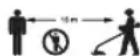
Keep safe distance -The distance between the machine and bystanders shall be at least 15m

Cutting width-The Max. cutting width of line trimmer

Disconnect the battery pack from the line trimmer before carrying out maintenance or cleaning work

This product is in accordance with applicable UK legislation.

To reduce the risk of injury, user must read the operator's manual.
IPX4 Protection from splashing water

Guaranteed sound power level.

Beware of thrown objects - Thrown objects can ricochet and result in personal injury or property damage. Ensure that other people and pets remain away from the line trimmer when it is in use.
Do not use the metal blades on the line trimmer

Line diameter-The Diameter of the nylon cutting line

This product is in accordance with applicable EC directives.
V Voltage
A Amperes mm Millimeter
cm Centimeter kg Kilogram

Direct Current ../min Per Minute
EN SPECIFICATIONS
| Voltage | 56 V = = | |
| No-Load Speed | Low speed range:3500-4800 min-1 | |
| High speed range:4000-5500 min-1 | ||
| Cutting Line Mechanism LINE-IQ FEEDING | ||
| Cutting Line Type 2.4 mm nylon | twist line | |
| Cutting Width 40 cm | ||
| Recommended Operating Temperature | 0°C - 40°C | |
| Storage Temperature -20°C - 70°C | ||
| Weight (without battery pack) 3.5 kg | ||
| Measured sound power level LWA | 90 dB(A)K=2.5 dB(A) | |
| Sound pressure level at operator's ear LPA | 77 dB(A)K=3 dB(A) | |
| Guaranteed sound power level LWA(measured according to 2000/14/EC) | 92 dB(A) | |
| Valuation of vibration ah | Front handle | 3.9 m/s2K=1.5 m/s2 |
| Rear handle | 2.7 m/s2K=1.5 m/s2 | |
The declared vibration total value has been measured in accordance with a standard test method and may be used for comparing one tool with another;
The declared vibration total value may also be used in a preliminary assessment of exposure.
NOTICE: The vibration emission during actual use of the power tool can differ from the declared value in which the tool is used; In order to protect the operator, user should wear gloves and ear protectors in the actual conditions of use.
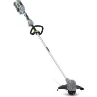
DESCRIPTION
KNOW YOUR LINE TRIMMER (Fig. A1)
- Variable Speed Trigger
- Rear Handle
- Locking Tongue
- 2-Speed Switch
-
Speed Indicator
-
Height Locking Collar
- Quick Adjustable Front Handle
- Quick-release Lever
- Hinge & Locking Bolt
- POWERLOAD™ Button
- Trimmer Head (with LINE-IQ Feeding)
- Cutting Line
- Release Tab
- Line-Cutting Blade
- Guard
- Ejection Mechanism
- Latch
- Battery Release Button
- Hex Wrench
- Shoulder Strap Loop
- Shoulder Strap
PACKING LIST (FIG. A1)
ASSEMBLY
WARNING: If any parts are damaged or missing, do not operate this product until the parts are replaced. Use of this product with damaged or missing parts could result in serious personal injury.
WARNING: Do not attempt to modify this product or create accessories not recommended for use with this line trimmer. Any such alteration or modification is misuse and could result in a hazardous condition leading to possibly serious personal injury.
WARNING: To prevent accidental starting that could cause serious personal injury, always remove the battery pack from the tool when assembling parts.
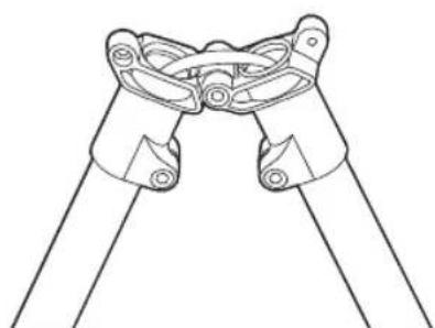
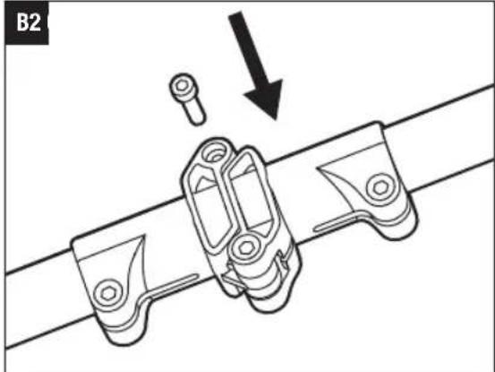
UNFOLDING THE SHAFT
WARNING: In order to avoid pinching your hands or fingers, do not hold the shaft at the joint.
WARNING: Do not attempt to start the trimmer until the shaft has been locked.
Unfold the shaft gently, ensuring the cable inside the shaft and lock it with the bolt by the supplied wrench (Fig. B1 & B2).
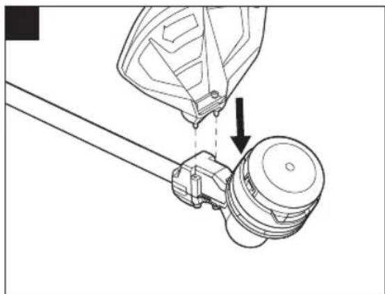
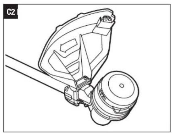
MOUNTING THE GUARD
WARNING: Always wear gloves when mounting or replacing the guard. Be careful of the blade on the guard and protect your hands from being injured by the blade.
WARNING: Never operate the tool without the guard firmly in place. The guard must always be on the tool to protect the user! When the guard is fixed, never attempt to remove or adjust the guard, if a replacement is needed, it should be performed by a qualified service technician!
Position your trimmer so that the trimmer head faces up (Fig. C1). Align the guard mounting holes with the assembly holes and then lock the guard on the shaft base with the two screws (Fig. C2).
NOTICE: Make sure the guard is fixed according to Fig. C1 & C2, any reverse fixing will cause great danger!
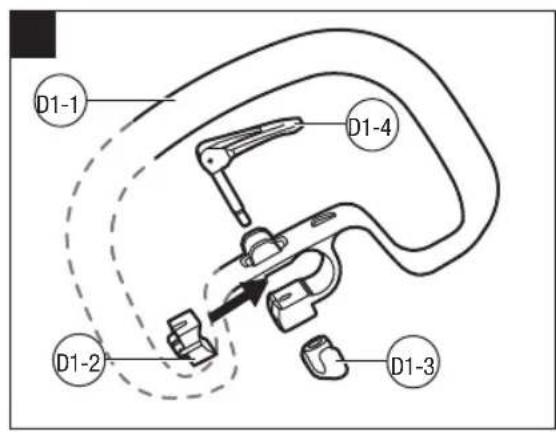
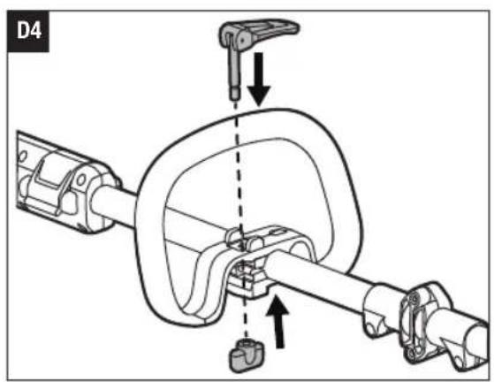
MOUNTING AND ADJUSTING THE FRONT HANDLE
- Loosen and remove the quick-release lever and wing nut from the front handle (Fig. D1).
D1-1 Front handle D1-2 Clamping block
D1-3 Wing nut D1-4 Quick-release lever
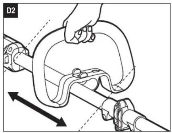
- Push the front handle onto the shaft within the mounting zone between the height locking collar and hinge (Fig. D2).
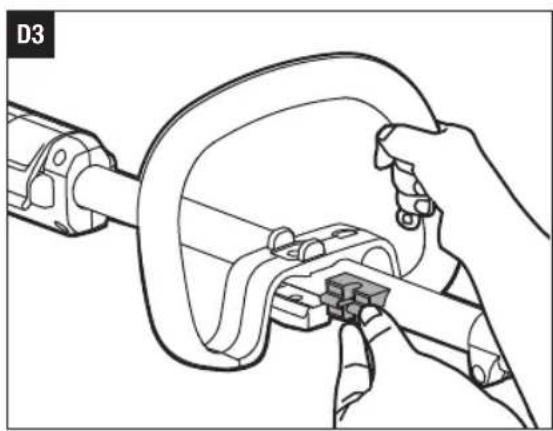
- Insert the clamping block into the handle slot (Fig. D3).
- Mount the quick-release lever and pretighten the wing nut. Make sure that the front handle is positioned upwards and points toward the top of the rear handle (Fig. D4).
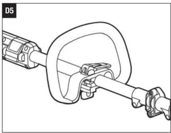
- Pull the quick-release lever up to move/rotate the front handle to a comfortable operating position, and then lock the quick-release lever (Fig. D5).
NOTICE: The front handle should be positioned on the shaft only within the mounting zone.
WARNING: The tool cannot be used without the front handle securely fixed.
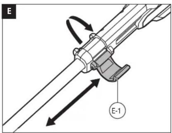
ADJUSTING THE TRIMMER HEIGHT
If the length of the shaft is not suitable for operation, you can adjust the length of the shaft through the height locking collar.
- Remove the battery pack from the trimmer.
- To adjust the trimmer height (i.e., shaft length), open
the height locking collar, and then slide the shaft up or down to desired height, securing it in place by depressing the height locking collar (Fig. E).
E-1 Height locking collar
NOTICE: The front handle may need to be repositioned after the trimmer height is changed.
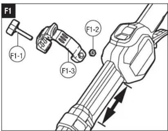
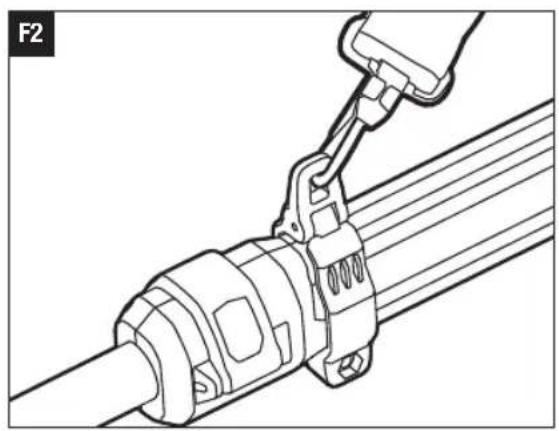
ATTACHING SHOULD STRAP
For safe and better operation, put the strap over one of your shoulders and across your back.
- Loosen screw knob and hex nut from the shoulder strap loop (Fig. F1).
F1-1 Screw knob F1-2 Hek nut
F1-3 Should strap loop
- Place the shoulder strap loop at a comfortable operating position within the installation zone, and then fix it by tightening the screw knob and hex nut.
- Depress the shoulder strap carabineer to open it and attach the shoulder strap to the hole on the strap loop (Fig. F2).
- Adjust the shoulder strap length and placement to a comfortable operating position.
WARNING: When an emergency occurs, take the shoulder strap off from your shoulder immediately, no matter what way the strap is on.
You should not use the single-shoulder strap and double-shoulder strap simultaneously.
When wearing the strap, make sure there is no other wearable interferes with the release and removal of the strap.
OPERATION
WARNING: Always wear safety goggles or safety glasses with side shield, along with hearing protection. Failure to do so could result in objects being thrown into your eyes and other possible serious injuries.
Trimming: grass and weeds from around porches, fences, and decks.
Cutting: grass that is difficult to reach using a normal mower.
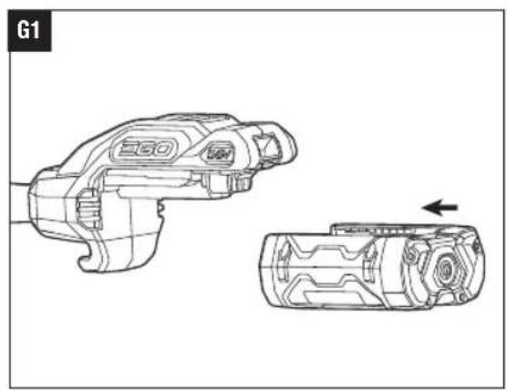
ATTACHING/DETACHING THE BATTERY PACK
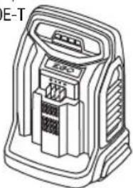
Use only with EGO's battery packs and chargers listed in Fig.A2
EN
Fully charge before first use.
To Attach
Align the battery ribs with the mounting slots and press the battery pack down until you hear a "click" (Fig. G1).
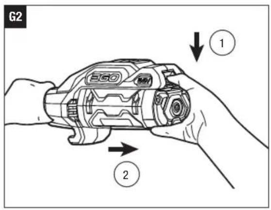
To Detach
Depress the battery-release button and pull the battery pack out (Fig. G2).
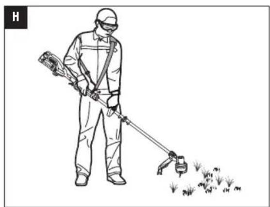
HOLDING THE LINE TRIMMER (Fig. H)
For safe and better operation, put on the shoulder strap across the shoulder. Adjust the shoulder strap length and placement to a comfortable operating position - hold the trimmer with both hands: one hand on the rear handle and the other hand on the front handle.
NOTICE: The trimmer head is parallel to the ground at a proper cutting distance without the operator bending over.
WARNING: When an emergency occurs, take the shoulder strap off from your shoulder immediately, no matter what way the strap is on.
STARTING/STOPPING THE LINE TRIMMER (Fig. I)
To Start
Move the locking tongue forward and then press the variable speed trigger.
The trigger is stepless speed adjusting. The more you pull up the trigger, the higher speed it is.
I-1 Locking tongue I-2 Variable speed trigger
To Stop
Release the variable speed trigger.
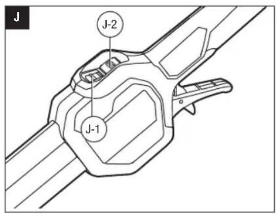
SPEED ADJUSTMENT FUNCTION (Fig. J)
The line trimmer has two speed setting. Press the 2-speed switch to change cutting speed between the low and high.
The speed indicator will display the active speed status: one light for low speed and two lights for high speed. The low speed range provides better control of the trimmer and longer operating time per charge.
J-1 Speed indicator J-2 2-Speed switch
USING THE LINE TRIMMER
Clear the area to be cut before each use. Remove all objects, such as rocks, broken glass, nails, wire, or lien that can be thrown or become entangled in the cutting
attachment. Clear the area of children, bystanders, and pets. At a minimum, keep all children, bystanders and pets at least 15m away; there still may be risk to bystanders from thrown objects. Bystanders should be encouraged to wear eye protection. If you are approached, stop the motor and cutting attachment immediately.
Before each use check for damaged/worn parts
Check the trimmer head, guard, shoulder strap, shoulder strap loop, and front handle. Replace any parts that are cracked, warped, bent, or damaged in any way.
The line-cutting blade on the edge of the guard can dull over time. It is recommended that you periodically sharpen it with a file or replace it with a new blade.
WARNING: Always wear gloves when mounting or replacing the guard or when sharpening or replacing the line-cutting blade. Note the location of the blade on the guard and protect your hands from injury.
Check for blockage of the trimmer head
- To prevent blockage, keep the trimmer head clean. Remove grass clippings, leaves, dirt and any other accumulated debris before and after each use.
- When blockage happens, stop the line trimmer and remove the battery, then remove any grass that may have wrapped itself around the motor shaft or trimmer head.
After each use, clean the trimmer.
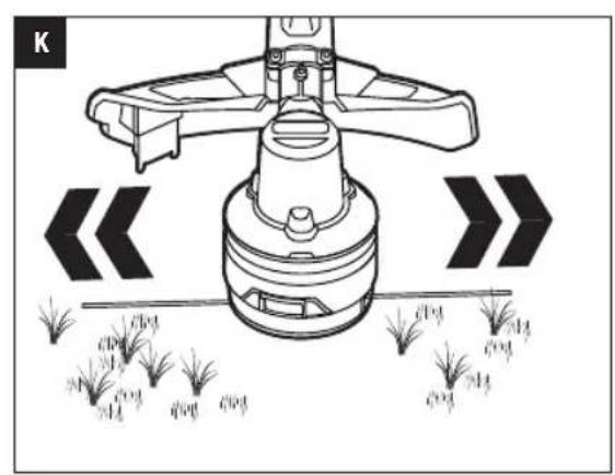
ADJUSTING THE CUTTING LINE LENGTH
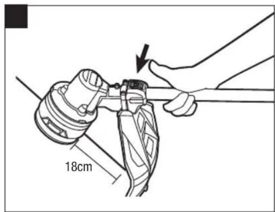
The Line-IQ feeding trimmer head is equipped with advanced technology.
If either end of the cutting line wears less than 18cm during trimming, the trimmer head will release cutting line automatically, and the extra part of the cutting line will be cut off by the line-cutting blade (Fig. K).
NOTICE: No need to tap the trimmer head to release the cutting line. If you feel a slight tremor of the trimmer head when trimming the grass, it is the cutting line being automatically released.
WARNING: Do not remove or alter the line-cutting blade assembly. Excessive line length will cause the motor to overheat and may result in serious personal injury.
LINE REPLACEMENT
NOTICE: Always use the recommended nylon cutting line with a diameter of 2.4mm
Using line other than that specified may cause the tool to overheat or become damaged.
WARNING: Never use metal-reinforced line, wire, or rope, etc. These can break off and become dangerous projectiles.
The line trimmer is equipped with an advanced POWERLOAD™ system. The cutting line can be wound onto the spool simply by pressing a single button. Loading a full spool can usually be completed in 12 seconds. Avoid repeated operation of the winding system in rapid succession to reduce the possibility of motor damage.
- Remove the battery pack.
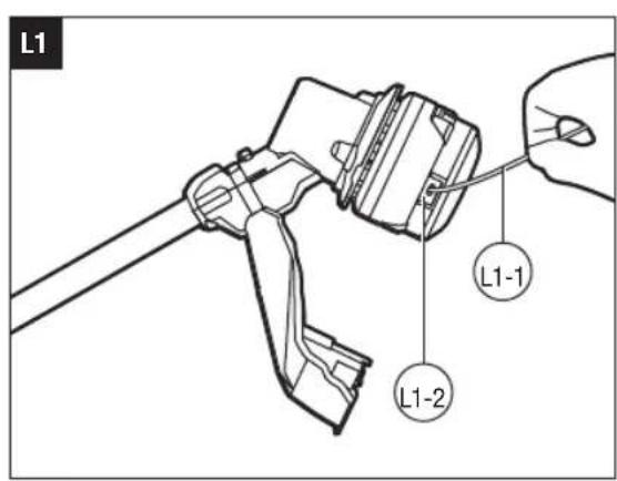
- Cut one piece of cutting line 4 m long.
- Insert the line into the eyelet and push the line until the end of the line comes out of the opposite eyelet (Fig. L1).
L1-1 Cutting line L1-2 Eyelet
NOTICE: It is not necessary to align the eyelets in order to insert the cutting line. If the line cannot be inserted into the eyelet, mount the battery pack onto the trimmer, then press the POWERLOAD button briefly to reset the winding mechanism.
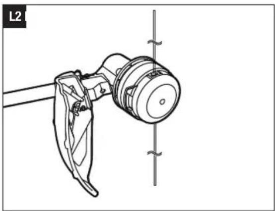
- Remove the battery pack if it has been mounted onto the trimmer in step 3.
- Pull the line from the other side until equal lengths of the line appear on both sides of the trimmer head (Fig. L2).
- Install the battery pack onto the line trimmer.
- Press and hold the POWERLOAD button to start the line-winding motor. The line will be wound into the trimmer head continuously.
- Watch the remaining line length carefully. Prepare to release the button as soon as approximately 22 cm of line are left on each side. Briefly press the line loading button to adjust the length until 18 cm of the line is showing on each side (Fig. L3).
NOTICE: In case the line is pulled into the trimmer head by accident, open the head and pull the cutting line out from the spool. Follow the section "RELOADING THE CUTTING LINE" in this manual to reload the line.
RELOADING THE CUTTING LINE
NOTICE: When the cutting line gets stuck in the trimmer head, you will need to remove the remaining
cutting line from the trimmer head and follow the steps below to reload the line.
- Remove the battery pack.
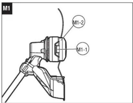
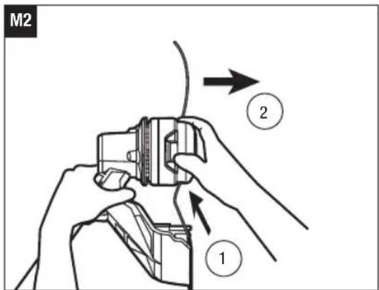
- Press the release tabs on the trimmer head and remove the lower cover assembly of the trimmer head by pulling it straight out (Fig. M1 & M2).
M1-1 Release tab M1-2 Lower cover assembly
- Remove the cutting line from the trimmer head.
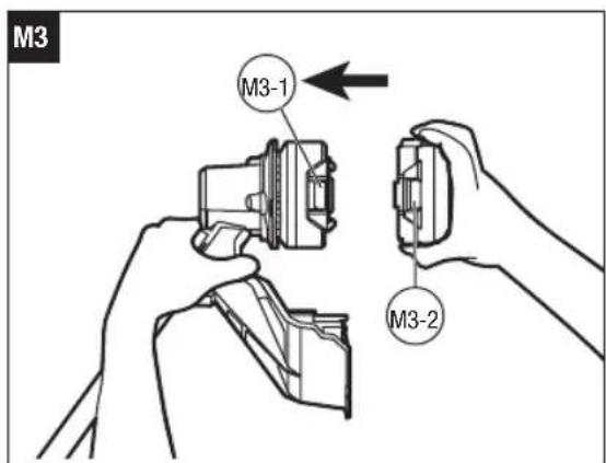
- With one hand holding the trimmer, use another hand to grasp the lower cover assembly and align the slots in the lower cover assembly with the release tabs. Press the lower cover assembly until it snaps into place, at which time you will hear a distinct click sound (Fig. M3).
M3-1 Release tab M3-2 Slot
- Follow the instructions in the "LINE REPLACEMENT" section to reload the cutting line.
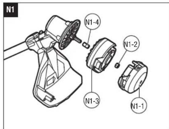
TRIMMER HEAD REPLACEMENT
WARNING: If the head loosens after it is fixed in position, replace it immediately. Never use a trimmer with a loose cutting attachment. Replace a cracked, damaged or worn-out cutting head immediately, even if damage is limited to superficial cracks. Such attachments may shatter at high speed and cause serious injury.
Know the trimmer head (Fig. N1)
| N1-1 | Lower cover N1-2 | Nut | |
| N1-3 | Spool assembly N1 | -4 Bushing |
To remove the trimmer head
- Remove the battery pack.
- Press the release tabs on the trimmer head and remove the lower cover of the trimmer head by pulling it straight out (see Fig. M1 & M2).
- Remove the cutting line from the trimmer head (Fig. N2).
- Wear gloves. Use one hand to grasp the spool assembly to stabilize it and use the other hand to hold an impact wrench (not included) to loosen the nut in a counterclockwise direction (Fig. N3).
| N3-1 | Nut N3-2 | Impact wrench (not included) |
EN
- Remove the spool assembly and bushing from the motor shaft. Save the bushing for later assembly.
- Replace with a new trimmer head and mount it in following steps.
To install the new trimmer head
- Mount the bushing in motor shaft and mount the spool assembly into place. Use an impact wrench to tighten the nut.
- Mount the lower cover assembly (see Fig. M3).
- Reload the cutting line.
- Start the tool to see whether the line trimmer will work normally. If it does not, reassemble as described above.
MAINTENANCE
WARNING: When servicing, use only identical replacement parts. Use of any other parts may create a hazard or cause product damage. To ensure safety and reliability, all repairs should be performed by a qualified service technician.
WARNING: To prevent serious personal injury, remove the battery pack from the tool before servicing, cleaning, or removing material from the unit.
CAUTION: Obstructions in the vents will prevent the air from flowing into the motor housing and result in overheating or damaged of the motor.
CLEANING THE UNIT
Clean the unit using a damp cloth with a mild detergent. Never let any liquid get inside the tool; never immerse any part of the tool into a liquid.
- Do not use any strong detergents on the plastic housing or the handle. They can be damaged by certain aromatic oils, such as pine and lemon, and by solvents such as kerosene. Moisture can also cause a shock hazard. Wipe off any moisture with a soft, dry cloth.
Use a small brush or the air discharge of a small vacuum cleaner brush to clean the air vents on the rear housing.
- Keep the air vents free of obstructions.
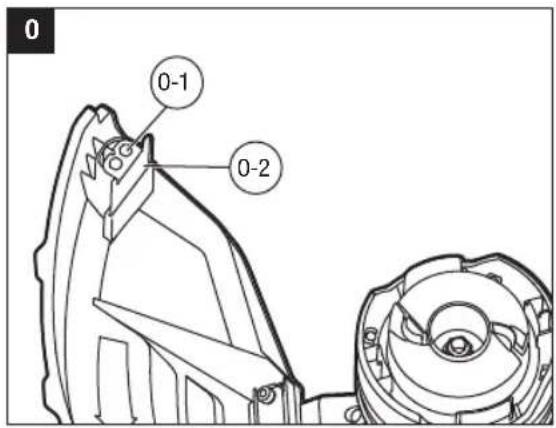
SHARPENING THE LINE-CUTTING BLADE
WARNING: Always protect your hands by wearing heavy gloves when performing any maintenance on the line-cutting blade.
- Loosen the two screws and remove the line-cutting blade from the guard (Fig. 0).
0-1 Screws 0-2 Line-cutting blade - Secure the blade in a vise.
- Carefully file the cutting edges of the blade with a fine-tooth file or sharpening stone, being careful to maintain the original cutting-edge angle.
- Replace the blade onto the guard and secure it in place with the two screws.
STORING THE UNIT
-
Remove the battery pack from the trimmer.
Clean the tool thoroughly before storing. -
Store the unit in a dry, well-ventilated area, locked-up or up high, out of the reach of the children. Do not store the unit on or adjacent to fertilizers, gasoline, or other chemicals.
Protecting the environment
Do not dispose of electrical equipment, used battery and charger into household waste! Take this product to an authorized recycler and make it available for separate collection. Electric tools must be returned to an environmentally compatible recycling facility.
TROUBLESHOOTING
EN
| PROBLEM CAUSE SOLUTION | ||
| Line trimmer fails to start. | The battery pack is not attached to the trimmer. No electrical contact between the trimmer and battery. The battery pack is depleted. The lock off switch is not being moved forward before depressing the variable speed trigger. The motor shaft or trimmer head is bound with grass. | Attach the battery pack to the trimmer. Remove battery, check contacts and reinstall the battery pack. Charge the battery pack. Move the locking tongue forward and then press the variable speed trigger. Remove the grass from the motor shaft and trimmer head. |
| Line trimmer stops while cutting. | The guard is not mounted on trimmer, resulting in an overly long cutting line and motor overload. Heavy cutting line is used. The battery pack or line trimmer is too hot. The battery pack is disconnected from the tool. The battery pack is depleted. | Remove the battery pack and mount the guard on the trimmer. Use recommended nylon cutting line with diameter 2.4 mm. Cool the battery or line trimmer. Re-install the battery pack. Charge the battery pack. |
| Trimmer head will not advance line. | The motor shaft or trimmer head is bound with grass. There is not enough line on the spool or the line breaks from the eyelet. The line is tangled. The line is too short. Heavy cutting line is used. Trimmer head malfunction. | Stop the trimmer, remove the battery, and clean the motor shaft and trimmer head. Remove the battery and replace the cutting line following “LINE REPLACEMENT” section in this manual. Remove the battery; remove the line from the trimmer head and rewind following “RELOADING THE CUTTING LINE” section in this manual. Remove the battery and pull the lines manually while alternately pressing down and releasing the trimmer head. Use recommended nylon cutting line with diameter 2.4 mm. Call EGO Customer Service for help. |
EN
| PROBLEM CAUSE SOLUTION | ||
| Trimmer head continues to release line automatically. | Light cutting line is used. | Use recommended nylon cutting line with diameter 2.4 mm. |
| Grass is wrapped around trimmer head and motor housing. | Cutting tall grass at ground level | Cut tall grass from the top down, removing no more than 20 cm in each pass to prevent wrapping. |
| The blade is not cutting the line. | The line-cutting blade on the edge of the guard has become dull. | Follow instructions to sharpen the line-cutting blade with a file or replace it with a new blade. |
| Cracks on the trimmer head | The trimmer head is worn out. | Replace the trimmer head immediately following “TRIMMER HEAD REPLACEMENT” in this manual. |
| The cutting line cannot be wound into the trimmer head properly. | Improper cutting line is used. Grass debris or dirt has accumulated in the trimmer head and blocked the movement of line spool. Motor is overheated due to repeatedly operating the line winding system. Low battery capacity The line is not wound into the spool assembly. Trimmer head is defective. | We suggest that you use EGO original nylon cutting line. If using EGO nylon line and the problem persists, please call EGO customer service for advice. Remove the battery, open the trimmer head clean it thoroughly. Let the line trimmer work under no load for a few minutes to cool the motor, then try to reload the line. Charge the battery Pull out the line and reinsert it. Call EGO Customer Service for help. |
| The cutting line cannot be passed through the trimmer head when inserting the line. | The cutting line is split or bent at the end. | Cut the worn end of line and reinsert. |
WARRANTY
EGO WARRANTY POLICY
Please visit the website egopowerplus.eu for full terms and conditions of the EGO Warranty policy.
ALLE ANWEISUNGEN LESENI!

m = 311 ;
LISTA DE PEÇAS (IMAGEM A1)
MONTAGEM
INHOUD VAN DE VERPAKKING (AFB.A1)
MONTAGE
HET APPARAAT SCHOONMAKEN
HET APPARAAT OPBERGEN
RENGORING AF APPARATET
OPBEVARING AF APPARATET
TapaHTnpOBaHHbI yPOBeHb 3ByKOBOI MOUHOCTN
HeicnpaBbIe 3nEKTpUeCKne
yCTpoiCTBa HeIb3ra BblbpacbIbTaB
BMecTe C6bl-TOBbIM MycopoM. CdaBaIte
INX BAbotu3OBaHHbIe NyHKtbi c6opa n
yTNIIN3aUN.

OcteperaItecb O6paCbIbAebMbxO6beKToB.
O6poWeHbIe npEIMTebl MOyT OTCKOHTb
n PnBeCTN K TpaBMam NIN NOBpeXdEHIO
mMyIecTBa.Y6eIMTeCb, YTO Dpyrme IIOu
n XkBOthie HaxoJrTCa Ha paccToHNOT
paboTaIoUero TpmmMepa C neckoi.
Co6HIOaIe 6e3oNaChyIO mNCTaHcHIO.
PacctOraHHe Mekdy yCTpoiCTBOM
nIOCTOpOHmIM NuaAMn DOJNKHO
coCTaBnTb He MeHee 15M.
He nCnoB3yIne CdaHHbIM TpMMepom C neckoM MetaIIHueCKne Je3BnA.

MaKc. ⅢpHa pe3aHn TpMMepa c JeCKoI

CoOTBeTCTByeT OCHOBbIM Tpe6oBaHnM CTaHdaptOB Be3onacHOCTN EbPone-cknx DupeKTHB.

JaHHeu3dJeIe COOTBETCTByeT DeNCTByIOUcemy 3aKoHOdaTeNbCTBy BeNKo6pntAHn.
B HanpajkeHne
AAMnep MM MmIIMMeTp
CM CaHTIMMeTp Kf KInOrpAMM

IOCTOHHbI TOK 06/MN H B MNHyTg
TEXHNUECKNEXAPAKTEPNCIKN
KOMJIeKT NOCTABKN (PNC.A1)
C5OPKA
A PEPENPPEKDEHNE. Ecn KaKe-Im6o cactn NOBpeKDeHb INN OTCyTCTBYOT, He NCNoJIb3yIte yCTPOINCTBO, NOKA OHN HE 6ydyT yCTaHOBnEHbI. IcNOb3OBaHHe YCTPOINCTBA B CNYuee NOBpeXdHn INN OTCYCTBnA ChTeM MoKeT PnIBeCTN K NOnyuHIO cepbe3HO TpaBMbl.
A NPEyPEXDEHNE. He nbTaItecb n3MeHb KOHCTpyKuHr TpMMepa HIN HCNoJIb3OBArB He peKoMeHDoBaHHbIe IINr Hero DOIOHNHTeNBHbIe npCnOCo6NeHn. IOno6HoE n3MeHeHne CnITaETcR HeHaNExKaUIM NCNoJIb3OBAHnEM nCnOCo6CTByET BO3NHKOHeHn OAnCHOH CNTyaU, KOTOPa PnpBEdet K nONyHeHIO cepBe3HO TpaBMbl.
A PEPENPEXDEHNE. UTo6bI PpeoTbpaTnTb cnUaHoe BkJIOueHne ycTroCBa nONUyeHne cepBe3HO TpABMbI, nepeD c6opKoN3BNeKeITe aKKyMJIaTOP.
PACKIADbIBAHNEBAJIA
A NPEUYPEXDEHNE.Bo n36eXaHne 3aemnEHHpyk nn naIbceB He depKHTe BAn 3a WapHnp.
A NPEyPExKdEHHe. He nIbTaIteC b3aNcyTnB TpMMep Do Tex nop, noka Ban He 6ydet 3aФuKKpOBaH.
Octopoxho pa3noxte Bn y6eInTeCb,TO Ka6eJb HaxoHITcB BYTPn Bala. 3aФNKCpyTe BAN 60TOM c nomoubI npnnaeraemoro raeHoro kNocha (Pnc.B1 n B2).
YCTAHOBKA LIMTKA
NPEDYNPEXDEHNE.BcerdaHaedeBaTe nepaTkn npn yctahOBKe n demoHTaxe uNTka. OcTepeaTecb le3Bna Ha uNTke n 6bePeIte pyknt onpe3OB.
A NPEYNPEXDEHNE. HnKoIa He nCnOJIb3yIte yCTpoiCTBO 6e3 HaedxHO yCTaHOBNeHHoro 5NTka. 5NTOK BCERda DOnJKeH 6bITb YCTaHOBNeH Na YCTpoiCTBO IIN 3aUNTbI NpIb3ObaTeN! He nbITaTEcb CHMaTa bNN perynipOBaTb yCTaHOBneHHbI 5NTOK. Ecnn 5NTOK Heo6xoIMMo 3aMeHtB, 3Ty paobTy DoJIkeH BblIOJIHHTb KBAInuΦnUPOBaHH b CnEuaNlncT no O6cnyKnBaHIO!
PacnoJoxnTe Tpmmpe rnoOBK BBepx (Pnc.C1). CoBmectnte KpenekHbIe OTBepCTna COTBepCTnMa nIyctahOBKn, a 3aTeM 3aΦNKcpyuTe IITOK Ha OCHOBAHIN Bala npn NOMOUs DByx BHTOB (Pnc.C2).
PIMMEUAHNE. Y6eHntecb, YTO uTOK yCTaHOBJEH TAK, KAK NOKa3aHO Ha Pnc. C1 n C2. IIO6oe dpyroe noOnKeHne MOXET 6bIb OUYH ONAChbIM!
YCTAHOBKA IN PEYINPOBKA INPEEDHEI PYKOKTNI
1.Ocna6bTe nCHIMnTe 6bICTropa3beMHbI pyHar n 6apaKoBvIO raKy c nepeDHepykoTKn (Pnc.D1).
PERYUNPOBKA BbICOTblTPMMEPA
Ecnn dInna BaNa He noxDxOuNT DnB BbINONHReMo pa6oTbI, ee MOxHO OTpeRyIpOBaTb C NOMOuHo MyΦTbI fKcAun BBICOTbl.
- 13BnKeTe akkymyIaTOp n3 TpmmMepa.
- TTo6bI OTperyInpoBaTb BbICOTy TpIMMepa (T.e. DnHy Bana), OTKpoTe MyfTy fNkCaunn BbcOTb IN CdBnHbTE BaB BBePx NIN BHN3 Ha HyKHyIO BbcOTy. 3aTEM 3aФNKcnpuYe erHOHa MeCTe C NOMOuMyfTbI fNkCaunn BbcOTbI (Pnc.E).
E-1 Mydta qikcaum BBICOTbl
PIMMEYAHNE. Bo3MOXHO, Nocpe peynpOBKn BbICOTbl TpMMepa notpe6yeTcra n3MeHnTb noIOxHeNne nepedne pykoRTkn.
YCTAHOBKA HANJIeHOro PEMHr
Ipeep nepBbIM HcNoB3OBAHEm NOJHOCTbIO 3apnTe aKKyMnyTOp.
YctaHObka
CoBmectItepe6paakkymyIaTopaCkpeneKhbIMOTBepCTnMMN BCTaBBTe akkymyIaTOp Do 9eNCHa(Pnc.G1).
ChyTne
Haxmte KhoNky fKcaun aKKymyIaTopa n3BneKeIte aKKymyIaTOp (Pc.G2).
OBPAUHEHNE CTPMMMEPOM C JIECKOIN (Pnc.H)
IJa 60one 6e3oanchoN u yO6HO pa6oTb nCNOB3yTe HAnneHb peMeH. Otperynpyte DnHy nNoIOKeHne HAnneHoro pEmHa. Bo3MITE TpIMMep o6eMM pyKaAM 3a3aHIOu INpeDHOIO pyKoTKn.
PIMMEUHNE. TOnOBKa TpMMepa DoJHKa
pacnojaraTbca npapnnelbHO 3emne Ha TAKOM
pacctOAHIN, pni KOTOpom OepaTopy He HxKHO TAYbCn nepeRn6aTbcra.
PPEyIPEXDEHNE.B Cnyae BO3HKnHOBENYpe3buiHcNtuaHn HEmeJeHHO CHMITE PeMeHbCIIeHa IIObIM CIOOCoM.
BKIOUOHEH N BbIKIOUOHEHNE TPUMMEPA C JIECKOIN (Pnc. I)
3anyck
IpepeMeCTe 3aOpHbI RaBcK Bneped N HaKMITE Ha Kypok.
Kypok no3B0JraET nIaBHO peryIinpoBaT bCKopocTb. Yem CnIbHee HaxaTne Ha Kypok, TEM BIIe CKOpocTb.
1-13aIopHbIy3bUOK1-2Kypok
OctaHOBka
Otnyctnte Kypok.
ФУHKLЯ PREGYIMPOBKN CKOPOCTN (Puc.J)
TpMMep cNeckoIMeET dBa ckopocThbIX peXIMMa.
IyBb6opa Hn3Ko IIN BbcOKO CKOPoCTn pa60tbl
NCIOJIb3yTe DByxN03uONHbI nepeKlnOHTeB.
Bb6paHnaCKopocbOTo6paXaETcNOMoUbHnHNkATOpOB:JnH3KoNCKOPoCTNCBETNTC ODNHnHKaTOp,JIbBICOKO-DABa.Dnana3OH Hn3KnxCKopocTe obecneuBaet NyuHn KOHTpOnb HaTrpMMepom 60onee DnntelbHoe BpeMa p60tbi 6e3IO43apAkn.
A PEPENPEXDEHNE. HnKoHa He nCnoB3yTe ycIneHHyMoMetaIOMNeCKy, npOBONky, BepEByN.T.D. Actn 3nx MaTePnaNoB MoryT OTdEnrTaCBn OnaCHO pa3NetatbCBA CTOpOHbl.
Tpmmep c IeckoOBopyOBOAH yCOBepHcHBoaHHO CnCTeMoI POWERLOADTM. JnHa HAMatbIbAHnJleckn Ha KaTyuKy DoctatoHNO HaxKaTb Ha KhoNkY. POnHoe HAMatbIbAHne KaTyuKn O6bUH0 3aHmAeT He 6oone 12 cekyHd. YTo6bl UMeHbWHT BepoTHocTB NOBpeXdEHHaDbIrataTe, He DonyckaTme MHOROKpAtho pa60tbl CNCTeMbI HAMOTKN B 6bICTPO nocJeDoBaTeNbHOCTn.
1.ИЗБЕКЛТЕаKKуМУЯТОР.
2. OTPeKbTe Kcok JneKn dInHOH 4 M.
3. Bctabte necky By uko n npotraHnte ee taK, YtO6bI KOHeLneckn BblweN3 npOTBONIOJXHO yuKa (Pnc.L1).
L1-1 Pexyuza necka L1-2 yuko
RU
PIMMEYAHNE. PnBCTABKE NCEKN HET Heo6xOIMOCN BbipabHnBaTb yuKn. EcnI neCKy He ydaTeC BCTaNTb B yuKo, yctahOBnTE akkMyJrTop Ha TpMMep, 3aTEM KpaTKOBpeMeHHo Haxmnte KHONky POWERLOAD, YTO6bl C6pocntb MExAHnM HamOTKn.
4.ИЗВЕКЛТЕ АKKUMYЛТОР,ecnON 6bln yCTAHOBNEH TpIMMep npBbINONHEHm Wara 3.
5. BbITaHIne necky C npryoC tOPOhbl TAKIM Opa30m, YTO6bI c 06Enx CTOPOH rONOBKN TpMMepa NcKa 6bIJa OINHakOBOn DnHbI (Pnc.L2).
6.YctaHOBHTe AKKyMnyTOp B TpMMep C neckoI.
7. Haxmte n ydepkmbaute KhONky POWERLOAD, YTO6bl 3aNyCTnTB MOTOp. Jecka 6ydet CMotaHa B rONoBky TpIMMepa.
8. BHIMATEJIbHO CNEIITE 3aДПИHON JNECK. ByIbTe rOTOBBI OTNCTNB KONK, KAK TOLBKO C KaKdoI CTOpOHbIOCTaHETcR np6JIN3NTeBHO 22 CM Jnck. Nocne 3TORO OTPeryNpyTE DNNHY NECK KpaTtMM NaKaTmMn HA KONKY 3aRpy3KN, YTO6bIC KaKdOro KOHua OCTanOCb NO 18 CM NECK (Pnc. L3).
PIMMEUHNE.EcnnBcRNeCKaOKa3anacbCnyauHo 3aTAYTaBRONBOKy TpMMepa,OTKpoIe TOnOBKY N BbITAHNTe IeCKy n3 KaTyuKn.ДЯperynopOBKn Ieckn BbINONHTe INCTpykUuBpaZdene YCTAHOBKA JIeCKN daHHOrO pyKOBoDCTBa.
YCTAHOBKA JIeCKN
PIMMEYAHNE. Ecn pekyaJe necka 3acptpnaB roNOBKe TpMMepa, Heo6xOIMMo ydaNTb OCTaTKn neckn n3 rOOBKn N BbIOONHTb CneDyUOme DeIeCTBnA, YTO6bl CHOBA yCTaHOBtBNecky.
1.ИЗнКиTeаKKуМлТОр.
2. Haxmte Ha qKcTOpbl Ha roJbKe TpMMepa n NotHnTe HxKHO KpbIbky B cOpe, YTObI CHrTb (Pnc.M1 mM2).
M1-1ФнсатopM1-2HнжЯКpbшkaВсбоpe
3.ИЗБЕКТЕ рекуюпecку n3 rOJOBKN TpIMMepa.
4. YdepKINBA TRPMMep OJHO pyKO, dpyroynykoB03bMNTecb 3a HNKHIO KpbIuKy u COBMCTnTe na3bIB NHKHe KpbIuKe CfNKCaTOpAMn. PnKmTe HNKHIO KpbIuKy TaKIM o6pa3OM, yTo6bl OHa 3aΦHKcUPOBaIacb Ha MeCTe C XapaKTepHbIM UeJIYKOM (Pnc.M3).
M3-1ФнкаTop M3-2Прорeь
5.Интуким no yctaHOBKe peKyuEe JIeCKn CM.B pa3deJe 3AMEHAJIeCKN daHHORO pyKOBOcTBa.
| N1-1 Hnxkhy Kpbuuka N1-2 Ga Ka |
| N1-3 KaTuuka N1-4 BTuka |
ChrTne rONOBKn TpMMepa
1.ИЗВЕКИТЕАKKIMУЛТОР.
2. Haxmte Ha qKcTopbHa rOBoKe TpMMepa nNotAHTe HxHHOIO KpbIuKy, YTO6bl CHrTb (Pnc.M1 uM2).
3.ИЗБЛЕКИТЕ рекуцю Леску ИЗ РОВКИ ТРIMМЕР (Pnc.N2).
- HadehTe nepaTKn. ODoH pyKoI kpenko yepKbAte KaTyuKy, a Dpyro pyKoI OTkpyTne raKy npOTN VacOBO cTpeKN npn NOMOuYdApHoro raKOBepTa (He BxOJNT B KOMPNeKT) (Pnc.N3).
3ATOUKAJIIE3BnIДIJIOBPE3KNJNECKN
A PEPENPEXDEHNE. Pn BbINONHEHN IIO6bx pa60 no 06cnyKBAHNO ne3BnI nI Ope3Kn IeCKN BCEgda HaeBaTe npOHyIe nepaTKn.
1.Ocna6bTe DBA BnHTa n CHMNTe C uNTKa Ie3Bne nn 06pe3Kn neckn (Pnc. O).
Prad staly .../min Na minute
SPECYFIKACJA
POLITYKA GWARANCYJNA EGO
A CSOMAG TARTALMA (A1 ABRA)
ÖSSZESZERELEŠ
HU
m = 311
IPOsAPTHsH KAI PYOMIEH THMIPoETINH XeipoABH
- Xaaapwote kai apaipeote to oxo ynpnyopns aotodoeaeuans kai tny tetaiaouda ato nvy pootivn xiepoala (Eik.D1).
LUGEGE KASUTUSJUHENDIT
OHUTUSSÜMBOL
LcBnBip6BjDnOBiJaeHHHOMy 3aKoHOdaBCTBy BENNKo6pntaHII.

3 MToIO 3MeHWeHH Hn3Nky OTPMaHH TpaBM KOpNCTyBaH NOBHeH IPOHTaTIN Noc6NHK 3 EcKnnyataa.
IPX43axnct BID 6pH3OK BOIN

TapaHTOBaHm piBHeB 3ByKOBoI notyKHOCTi.

OctepiraTecra BiKHyTnx npedmeti B- iDKNHyTI npedmetn MOKyb BiPINKoWETnCb i Pn3BcTe n Do TpaBM abo noKoKeHb MaHa. IpekoHaTecra, 0i iHsi IKnTa DomaHi TBapHH 3aNnaTObca Ha BiCTaHI Bi NICKOBOR TOpMepa, KOJI BII HIKOPNCTOBycBcR.
He BnKOpNCToBMyTe MeTaneBi ne3a 3 JICKOBIM TpMepom.

IiameTp nickn - iiametp HeJIOHOBOi pIXyOoi nickn

Ley Bnpi6 BiDnOBiJae YHHHm DnpeKTHBaM EC.
UK
B Hanpyra
AAMnepmMMMijimeTp
CM CaHTmEtprk KInorpamn

IocTINHnCTpym.../XBHa XBUNHy
PERYJIIOBAHHB BNCOTNTPMMEPA
KIO DOBXINHABaHE NIXOXOHTbIPO6OTN,BIMOKETe BIDPERYIOBATN DOBXINHY Bana 3a DONOMORHOCTONOPHOro KINb4nDnFAICauBVCOTN.
- BnMItb akymyTOpHy 6aTapeHo 3 TpImepa.
- Ⅲo6 BiDpeRyHOBaTH BNCOTy TpMepa (TObTo IOBxNHy CTpNKH), BiKpnIte CTOnOpHe KJIbue BNCOTn, a NOTIM NOcyHbTe CTpKKeH bROPy a60 BHN3 Ha Ntpi6Hy BNCOTy, 3aΦiKcYBaBm Ioro Ha MlCi JHaTnCKaHHaM Ha CTOnOpHe KJIbue BNCOTn (Pnc.E).
E-1 Komip i3 φikcaüe H BCOTn
PIMITKA. PpeHIO pyky, MoJINBO, noTpi6HO 6yde NOBTOPO BIDPERYIOBATN NICNA 3MHN BUCOT TpIMepa.
KPINJIENHHIJIeYOBOPOPEMEHRA
ДябзneуhoTаefeKTHBHIoipo6ToHaJaHITbpeMihbHaOHe nneye TaHa cnHy.
- Nocna6te TBnHT iueCTnIpaHny raHy netni nneYOBoro pemeHa (pnc.F1).
TPUMAHHTRPMATNJICKOBNI TPIMEP (pnc.H)
ДябзneHoI ta kpaIo pObTo nHaJaTae peMieUc ЧepeЗпес. BiPperyIouTe DOBxHNY Ta po3MiueHn ПлсоВOrO peMeHЯТak, 6yNo 3pyHNo pAciuBoTn - ТримаTe TpIMep oboma pykAm: OndHIO pyKIO 3a 3aHIO pyKoRtKy, a IHsoO pyKIO 3a NepeDHIpyKoRtKy.
PIMITKA. TOnOBkA TpImepa Mac 6yTu npapaneBHO 3emNi Ha DoCTaTHi BiDCTAHI dny piaHHn, OpeaTop He NOBHeH HArHHTCA.
A NONEPEDXEHHA. KOnI TpannIeTbcB
Ha3BnayHa CnTyauiz, HeraHNo 3HIMiT pNeouBn peMihb i3 pneua, He3aIeXHo BiD TORO, y kN cnocio odrgHeHO peMiNb.
3ANYCK/3YNIHKA JICKOBOTO TPIMEPA (pnc.1)
3anyck
IpeMeCiTb 3anipHn r3uOK Bnepe,notim HAtmChiB nyckOBn IepemKau 3i 3MHNOU WbNdkicTIO.
LcBaxinb cnyrE nnaabHoro peryIIOBaHH WbNkOci. 6iNbue BN niHimaTe Baxinb,TO Bnue WBnKICb.
IpepeBipTe, Hn HacaKny-tpmep He 3a6JIOKObaHO.
1063ano6iTn 3acMieHH,TPMaTe HacaKy-tpMe y nctoti.BuDAnIe o6pi3Kn TpaBn,PiCTa,6pyd i 6yDb-kae iHwe CMITTA,IO CKynHIOcA,do i niCnKoKHoro BkOPOUCTAHN.
KUcO CTaIOcRAcMueHHe,3yNnHtB NICKOBm TpIMep I BnMIb aKymyIaTOp,a NOTIM BuaJIb yCIO TpaBy, RaMa MoIHa HAMOTaTcH Ha BaI MoTop a 6o HacaIky-TPmep.
Picna Koxhoro BnKOpncTahn OuchTe TpMep.
PERYJIOBAHNNIOBXNHNPIXQOJIICKN
TOnOBKa TpMepa IJn noJauI Line-IQ OchauHa nepeoBmIM TexHONOTMI.
Kuio nuc o6p3aHn 6yNb-kyn KHeCb nickn 3HOwSyTbCm HnHa 18 cm, TpImepHa rOIOBka ABTomauHo BnUyCKae NICKY, i3aBa YactHa nickn BiDpiaeTbCn Jeom dno6p3aHHn IICKn (Pnc. K).
PIMITKA.He notpi6H NoCTyKbATn NO TpImepHiI roNoBci, uo6 3BilbHHTn NcKy. JkUO Bu BIDuyBaTe NeKe TpeMTHH RoNoBKn TpImepa NiJ cac CTpIKKn TpaBN, ce O3Haue, UO pIXyA NcKa ABToMaTHHO BnNyckaETbcra.
A NONEPEIXEHH. He BuaIaIte Ta He 3MiHouTe pixyue ne3o B 36opi. HAmipHa DOBxHnA Iickn np3BeDe Do nepepiBy MOTopa Ta MoKe cnpuHHTn cepno3Hi TpaBMn.
3AMIHA JICKI
PIMITKA.3aBXn BnKOpncToByTe peKoMeHDoBaHy HeJIoHOby pIKyU nicky 3 diametpom 2,4 MM.
BnKOpNCTaHnIHooI NCKn, BiDMHHoBI yka3aHOi, MoKe CnpuHHTn nepepiBaHH nctpyMeHa a6o Ioro NOWKoDKeHH.
NONEPEDXEHH. HikoJI He BnKOpNCToBnyTe apMOBaHy MeTAlOM NICKy,dpIT,MOty3KY TOIO.BOH MoKyTB 3IaMaTncb i cTaTN He6e3neuHMn ChapJaAMn. JickOBn TpIMep OcHaueHn nepeoBOHO CnCTeMoTO POWERLOADTM.PiKyy NICKy MOxHa HamOTaN Ha KOTUkY IpOCTNM HATNCKaHHM ONDHe KONKn. 3aBaHTaKeHHN NOBHOI KOTUKN MOKe 6TyN BnKOHaHO 3a 12 cekyHd.He BnKOpNCToBnyTe CnCTeMy HAMOTyBaHH KJIbka pa3IB nocinb,063MeHwNTn MmOBipHicTb nowKOxEHH MoTopa.
- BmmitbakmylantopHy 6atapeo.
- BiDpijXTe шMaTOK nickn 3aBdoBxKn 4 M.
3.ПрocуньтлickyуВУшкoviHaTиckайТеHaNicky,doKII KHeUbHeBnDE 3 npOTnEJxHOrO ByuKa (pnc.L1).
L1-1 PjxHa licka L1-2 Byuiko
PIMITKA. He 06OB'3KOBO BUPIBHOBaTN JIOBepCN, 0o6 BCTaBNTn pikyJ nicky. JKIo NICKy HE MOKH BCTaBNTn y ByuKo, BCTaHOBITb akymyIaTOp Ha TpIMep, a NOTIM KopoTko HATNCHTb KONkY POWERLOAD, 0o6 cKnHytn MEXaHI3M HAOTyBaHHA.
- 3HimTb akymyIaTOpHy 6BaTapeHO, kUIO ii 6byNO BCTAHOBJIeHO Ha TpIMep HA KpOci 3.
- BntyHnItb nicky 3 IHwO CTOpOH, DOKN He 3'ABtbcpibHa kInbKiCTb nickn 3 o6ox 6okIB roIOBKn TpIMepa(pnc.L2).
- YctahOBiB akymyIaTOp Ha JicKOBn TpIMep.
- Hatncihb i ytpmmye KhoNky POWERLOAD, 0o6 3anyctnMOTOpHAMOTyBaHnIa NICKI.Iicka 6yde 6e3nepepbHO HAMOTyBaTcH a TpImepHy rONOBky.
8.YBaXHO CTeXe 3a DOBXHNOIO NICK,IO 3aNuaTeBcI. PnroTpyTeCe BIDNyCTIn T KONky, 0oHIO 3 KOxHoro 6Oy 3aNnHTbCp npi6n3HO 22 cm NICK.HATNCiHb i BIDNyCTtB KONky 3aBaHTaKeHHa NICK,io6 BipeYJIOBAtn DOBXHny NICK Do 18 cm I3 KOxHoro 6Oy (Pnc.L3).
PIMITKA.YBnadky,AIO NOIcKa BnadkoBOB BTRHynacB rONOBKY TpIMepa,BIDKPNTE rONOBKy Ta BNTHb pIXyNICKY 3 KOTUKN. D0TPMUYTeCB po3DIny 《3APABJIeHHRAPIXyOJ NICK》B cBOMy nociHNky, 3o6 3anpaBnTn NICKy.
3ANPABNEHH PIKyuOJI NICKN
PIMITKA. KOnPiKyuNicKa 3aCtprB B roNoBci TpMepa, Bam nOpi6Ho 6yde BnDaJIInT pKiHy NICKy, 03aIImuNacra, 3 rONOBKn TpMepa i BnKOHaTu HabeDeHi HnKHe KpOKu, 5o6 3anpaBHTn NICKy.
- Bmmitb akymyIaTOpHy 6aTapeNo.
- Hatncitb Ha qikcatopn Ha tonobci Tpmepa Ta 3HIMtB HxKHO KpnuKy B 36opi, BntraHyBun ii (pnc. M1 i M2).
M1-1 FikcaTop M1-2 Hkhr KpUka B 36opi
- BnmiTb pixyuy nicy 3 roIobKn TpImepa.
- Tpmaouo odHIO pykoTO TpMep, iHIOy pkoio
B3bMtbc3a HNKHIO KPNUky B 36opi Ta cymicttBTBOPn B HNKHIN KPNUJI B 36opi 3phiKATOpAMnHaTNCaIte Ha HNKHIO KPNUky B 36opi,DOKN BOHHe 3aΦICyETBCBa HA MICU, I TOJi BN NOUYeTE Bnpa3HNI 3Byk KnaaHn (Pnc.M3).
M3-1Φikcatop M3-2Otpip
- DToPmMyTeCb IHcTpyKuJy po3dini «3AMHA JICKN》,06 3anpaBnpiKyjny Nicky.
3AMIHA TONOBKNTPMMEPA
A NONEPEDXEHHA. RaKo KpINHeHr rONOBKn nocna6nOeTbcra nicra fikcauiB II noJoxeHHi, HeraHIO 3amHITb II. HikoJI He BnKOpNCTOByTe TpMep i3 He3akPInNEHM pIXyHm npCtpoEM. HeraHIO 3amHITb TpichTy, noIKoDxEHy a60 3HOseHy pIXyHu rONOBKY, HabITb JkUO NOkOxDxEHNA8nEco6OIO Iwne NOBExHBeI TpiuHN. Taki HacaDNMOxyTB pyHyBaTHcH Ha BnCOki WbNkoCTi I npN3BecTN Do cepNo3Hnx TpaBM.
O3haHOMJIeHHraTOJIOBkoTo TpIMepa(pnc.N1)
| N1-1 Hижня кршka N1 | 2 Гаякa |
| N1-3 Ктушka в зборi N1 | 1-4 Втунka |
3HJTTI ROJOBK TpIMepa
- BnmiMbakmyIaTOpHy 6atapeko.
- Hatncitb Ha qikcatopn Ha ronobti pumepa Ta 3HIMtB HnKHHo Kpuu, BHTRhyu II (puc.M1 i M2).
- Bmmitb pikyu ncky 3 roNOBKn TpMepa (pnc.N2).
4.BdHnHb pyKabNKn. OndHcO pyKO b3bMItbcra 3a KOTyUkY B 36opi, uo6 CTa6i3yBaTn II, a IHuOpyKoTO TpMaIte ydApHn rAkoBepT (He BXoHTb y kOMnEKT), uo6 BiKpyTnTn rAky npOt IOnHHNKOBOI cTpiKN (Pnc.N3).
| N3-1 Γaɪka N3-2 | Удэрно raɪkoBERT (He BXODɪt b y KOMPNIekt) |
- 3HIMITb KOtyuKn B 36opi Ta BtynkY 3 BaNa MoTopa. 36epexitb BtynkY nna NoadanBworo 36npaHHa.
- 3amHbHa HOBY rONOBky TpMepa Ta BCTAHOBiB II, BnKoHabuN npeiueHi HxKy eii.
YCTAHOBJIeHHHOBoI rONOBKN TpIMepa
- YctahOBiTB BtyJKN y BaI MOTopa i BCTAHOBiTb KOtyuKy B 36opi Ha Micue. 3aTARHITb raiKy ydapHM raIKOBePTOM.
2.YCTaHOBIT HmKHHo KpMkky B36opi (mB.pnc.M3).
3. 3anpaBte pixkyu nicky.
4. 3aynctiB IHCTpymeHT, uo6 nepeBipuTn, uu NICKOBu TpIMep npauOe HOpMaIbHo. RaIoo Hi, NOBTOHO 36epiB Ioro, k ONcaHO Bnue.
OBCJYROBYAHH
A NONEPEDKEHHB.NBOKOPCCTOBYTe dIa
TEXHIOO 6cIyROBvAHnI IeIeHTNHi 3aIacTHn. BIKOPCTaHH 6yDb-IAKx IHINX YACTIN CTBOpIOE He63neky a50 MoKe npu3BeCTn Do nONOMKn BInpO6y. IIra rapaHTyBAHH 6e3NeKN Ta HadiHocTI Bci pemOHTHi po60TN NOBHeH NPOBODHT KBAJIΦIKOBAHn TEXHnI CneuaianCT.
PONEPENHEH.1063ano6irTcepno3HM
TpaBmam, BnMaTe akyMnyTopHy batapeo 3 IHCTpyMeHTa nepeD o6cnyroByaHHM, OOnuEHHM a60 BuIaNHeHHMaTepiAINiB i3 npNCTpO.
3ACTEPEXEHHH.3acmueHHBHTNRIHINX
OTBOPIB nepeuKOJkae npOHKeHHIO nobITpB KOpNc MOTopa i Moke np3BecTu do neperpby afo nowkoJKeHHa MOTopa.
OuHueHHNIPNUADY
OuHCTbTe npnnaBONTOIraHHIpKOIO 3MJKMMmHMM 3acobom.HikonHe donyckaiTe nOTpannnHp iDHN BcepeHy IHcTpMeHTa; HIKOn He 3aHypoHTe 6yNb-ky cactHy IHcTpMeHTa B pINHy.
He BnKOpNCbByTe CunBHi MmOci 3ac06Ha nlaCTNKOBOMy KOpNcI a6o pyuCi.BoH MoKyTb 6yt N OwKOJKeHI DeKMM apomatNHMM MacnAMn, HApNKlAxD XBOHMM I JIMMOHHM, a TAKOX PO3HNHKAMn, TAKMN YRac. Bonorictb TAKOX MOKe cTaHOBTN He6e3Neky ydApY. O6epExHo npotpiTB BOJORY M'KIO CYXIO TKaHHOHO.
BnKOpNCTOByIte HeBeENky uItkY a6o HeeBNKn nnnococ i3 BnDyBOM nobITpy dny OumueHHBENTNIaHnx OTbOpIB 33ady Ha Kopnyci.
He donyckaTe nepekptTBeHTnlaHmX OTbOpB.
3ATOUYBAHHIICKOBTOHOXA
PONEPEDKEHHA.3aBxdu 3axuauTe pykui
Ojrauoy Mlci npkabnki nI qac BkoHaHHa 6ydb-koTeXHiHO rO6cnyroBaHHa NICKOBOr HOxa.
- Nocna6Te DBA TBnHTn Ta 3HIMtB JICKOBn HIX i3 3axnCHoro kOxyxa (PNC.O).
0-1ΓBmHTnO-2IickOBmHix
2.3akpinitb hik y neaatax.
3. AkypaTHo 3aToCHb pixyHc KpOMKn HOxKa dpi6HM HAnnIKOM a60 ToCHNbHM KameHem, dbaUHN npO Te, Uo6 3epeRtn BuxiHN KyT pixyOi KpOMKn.
4.YctaHOBtB HIX Ha 3axuChn KOxuy Ta 3aipKcyIte IIMO DbOMA TBHNTAMN.
3BEPIAGHHIPIIADY
BnMItb akymyIaTophy 6aTapeo 3 TpImepa.
Ipepe36epirahnHm iNCTpymEnT Heo6xioHO peTeNbHO ONUCTNTN.
36epiraTe npunctpiy cyxomy,do6pe BEHTINbOBAHOMY,3aKPTOMy a6o BnCOKO p03taWOBAHOMY HeIOCTynOMy dIeTMeiMiCi. He 36epiraTe npunctpi 6iJIaMIhepaJIbHNx do6pmb, 6eH3nHy ta IHnx ximikatib.
3axncTdoBkinnn
He BkndaTe eNektpnHcO6naHaHH, akymyTOp i 3apAdnn npncptiy u no6yTOBI bIXoAn! BiHecitb ceBnpi6 abTopn30BaHOMy nepeo6nHyu HadaTe Ioro dIPOzDInbHorO 3bnpAHn. EJeKtpoiHCTpyMeHTn Heo6xIDHO nobepHyTN B nIpneMCTBO, 10 3aMa6Tbc8eKOnOriHcO63neUHO nepeo6ko.
UCYHEHHH HECIINPABHOCTEIN
He n3no3BaIte MeTaNHtE OCTpNtA H KOpDOBn TpIMep

山nHa ha p3aHe - MaKcImaHnHaTapekea 1nHa KaPdoB TpMep

A PEPDyPEXKHEHNE:3a da n36eHHeTepnuiuBaHe Ha pLcTe Hn npCTnTe CN, He dpkTeBana BcbneHaBeHO.
A NPEDyIPEXJEHNE:He ce onnBaIte da CTAPtIpate TpHMepe,doKATO BAHT e 3aKnIOeH.
Pa3bHETe Bana BHIMaTeJIHO, KATO OcNrypnte Ka6eNa BbTpE BbB Bana n ro fNkCpaIte C 6oNTa C DocTaBeHnraeueh knou (ΦIr. B1 n B2).
MOHTAX HA INPEINA3NTENIA
NPEyPEXDEHNE: BnHaHn Hocete pKaBnU, KOrato MOHTnpaTe NnN NOmehrTe npedna3nteJ. BHIMABaIte 3a HOka Ha npedna3nteN n npedna3BaIte pbueTe CNOT HapaHbAHe OT HOka.
A PEPENPEXDEHNE: Hkora He pa6oTe c MaunHata 6e3 npda3nteJrTa da e 3dpabO Ha mrcTO My. Ppda3nteJrT pr6Ba BNar Da e Ha MaunHata, 3a da npda3Ba NOpe6nte! Korato npda3nteJrT e fHKnpaH, Hkora He ce ONtBaIte Da n3BaJITe NIN da perynpate npda3nteJrA, aKO e Heo6xOIMma NOmHa, Tpr6Ba Da 6bJe n3BbpWeHa OT KBaINuPnpan cepBN3EH TEXHk!
Позиюнраite Trpimepa takaye rnaBata Ha trpimepa da coun Harope (ФИR.C1).ПОдразнete мontхнITE OTBOPuHa npedna3nteЯ cOTBOpTE 3a MOHTaxHm MEXAHn3bM n CJIeT TOBA 3axBaHete npedna3nteY BbpxOCHOBATA Ha BAana CDbata BnHTa (ФИR.C2).
BENEXKA: YBepete ce, Ye npednataeTeaakpenen Cbtnacho qnr. C1 nC2, BcraKo 3akpenBaHe Ha o6paTHO ige npuHn ronma onachocT!
MOHTIPAHE IN PEYINPAHE HA INPEHATA PbKOXBATKA
- Pa3xna6eTe n 3BaJeTe NoCTa 3a 6bP30 OCBO6OxJdAbaHe n KpNHaTata rAka OT npEHaTa pBkoXBAkA (ΦnR.D1).
| D1-1 | Рреда ръкхватуka | D1-2 3a | Тягац 6лок |
| D1-3 K | Кrimпача райка D1-4 | Лоста 6ьрзо освобождаване |
- Hatnche npedhata pkoBbTaKa Bbpy Bana B 3OHata 3a MOHTAK MeKdy 3aKIOyBaAsTa BnCOHHaTa
Yaka n NaHTata (Φn.r. D2).
- NocTabete 3aTgauu6IokB npope3aHa pkoXBtKaT (ΦnR.D3).
- MohtnpaIte NoCTa 3a 6bp3o OcB6oxkDaBaHe n npEbnPntEnHO 3aterHeTe KpUHaTATA raHa. YBepeTe ce, ye npEhHaT a pKoXBaTKa e no3nIOHpaHa Harope N CouN KbM BbpxHa Ha 3aHaTa pKoXBaTKa (Φnr.D4).
5.ИЗдрайе loctа 3a 6bp30 ocbo6xДаBaHarope,3a da npemecBaTe/3abpTne npedHaTa pkoXBaKaB yIObHO pa6TOHO nIOJKeHne, cIeKoETo 3aknOHTe loCTa 3a 6bp30 ocbo6xДаBaHep (ФИг.D5).
BENKKA: PpHnata pBkOXBtKa Tp8Ba Da 6bDe pa3noJKeHa BbpxY BaI cMoB 30HaTa 3a MOHTaK.
PPEyPExEHE: INHcTpymeHTbT He MoXe Da 6bIe n3no3BaH 6e3 CnrypHo 3aTeHa TpeHa pbkoXBAtka.
PERYJINPAHE HA BINGOHATA HA TPIMEPA
AkoIbIgHnHaTa Hbala He eNoxOJa 3a pa6ota, MoXeTe Da peryInpate IbJHKHaTa Ha Bana Ype3 JaKaTa 3a 3aKJIouBaHe Ha BcOChHata.
1.ИЗbaDéTe aKумlaTорнataбатepиOTТпмера.
2.3a da perynipate BncoHHata Ha Tpimepa (T.e. IbIIXHATA H BA),OTBOPETe RaTAt 3akIOvBaIa BnCOHNATA N CNEI TOBA IIb3HETe BAHaHRope Hn HAOny Do XeJHaHATA BnCOHnA, KATO 3akpeNITe Ha MRCTO Upe3 HaTNCaHe Ha RaKaTa 3akNHOBaIa BnCOHNATA (ΦmE).
E-1Ka3a3aknOuBaHeHaBnCOUHnHaTa
BENEXKA: PpeHaTa pkoXbKa MoKe da ce HaNoKn Da 6Ne pemeCTeHa CneI npOMraHa HbNcoUHata Ha TpIMepa.
3AKPENBAHE HA PEMbk 3A PAMO
3a 6e0nacna n no-do6pa pa6ota nocTabete peMbka Bbpxy eoHO OT pameHeTe HnapeHo Ha IbpaCn.
- Pa3xla6eTe BnHTOBTo KOnHe N IeCTOCTeHHata raKa ot KOHTypa Ha peMbka 3a pAmo (Φnr.F1).
| F1-1 | Кончеса вnett F1-2 | Лectureхетеня райka |
| F1-3 | Контур на ремька За памо |
- NocTabete KOHTypa Ha pembka 3a pamo B ydo6ho pa60THO NOIOXeHne B 3OHATA HA MOHTax n CJIed
TOBA rO fNkCpaIte, KaTo 3aTeHETe KOnHeTo 3a BnHTa N IeCTOCTeHHATA raKa.
- HatncheTe Kapa6nHepa Ha pembka 3a pamo, 3a da ro OTBOpnte n npKpeTe peMbka 3a pamo KbM OTbopa Ha pembka (fur.F2).
- PerynpaTe IbIINHaTn pa3noJoxHeHTo Ha peMbKa 3a pamo B yIO6Ho pa6oTHO nIOJoxHeHne.
PPEyPExEHE: Pn HnHnue Ha aBapnHa cnTuay, He3a6abHo rO CBanTe OT pAmTo CN, He3aBcIMNo NO K0n HauHH ce HAMpa pembla.
He Tp86Ba Da n3non3BaTe eHnueH n DBoe H pEmbK 3a pamo eHOBpeMeHNO.
Korato Hocnte pembka, HnKoe npyro npneHOCmO yctpoictbo He Tp86Ba Da npeu Ha oCbo6oxdabaHeTo n OCTpaHraBaHTo Ha pembka.
EKCPIIHOATAU
PENEPYPEXDEHNE:BnHaHn HocTe cTaHdapTHn npedna3Hn OuHa nHn npedna3Hn OuaHa CbC cTpaHnHa 3aunTa,3aeDNo CbC 3aunTa 3a cnyxa.AKo He ro HanpabNTe MoKe Da DoBedeDo N3xBbpIHe Ha npedMeTu KbM OUHTe BN dpyTN Bb3MOxHN cepno3HN HapaHbaHn.
Iopra3BaHe: TpeBa nPiIeBEn OTOKoIO BepaHn, orpaN nPiataFOpMn.
Kocene: TpeBa, KOTo e TpydHa 3a DoCTnTaHe npuynoTpe6a Ha oBnKHOBeHa Kocauka.
MOHTNPAHE/M3BAXDAHE HA AKMYJATOPHATA BATEPNA
H3non3BaIte eDnHCTBHeO aKymyIaTOpHN 6aTePmE G0 n 3apAHy uCtpoCTBa H36poeHH Bb A#r. A2.
3apeTe HanbIHO npedn PbBaTa ynotpe6a.
3a da 3akpennte
IopabhepepebataHaakymnatohpata6aepnna cMOHTaxhnte XneboBe HnatncheTe 6aepnra Haonny,doKaTo yyeTe "uPaKbaHe" (Phr.G1).
3a da n3BaJnte
HaTncheTe 6yToHa 3a ocBo6oxJaBaHe Ha 6aTepyraTa n3dbpnaIte akyMnyatopHata 6aTepyra HABbH (Φr. G2).
XBAUHAHE HA KOPDOBNA TPMEP (H)
3a 6e0nacna n no-dobpa pa6ota, noctabete pembka 3a pamo npes pamoto cn. Perynpaute nbjnxHaTa Ha pemka 3a pamo ro noctabete B ydoHo noIooxeHne 3a pa6ota -XbaHETepmepa c DBe pbue, eHnata pbka Ha
3aHaTa pBkoXBaTka, a DpyraTa Ha npedHaTa pBkoXBaTka.
BENEXKA: Tnabata Ha Tpimepa e ycnpedHa Ha 3emrHa npabINHO pa3ctOHe 3a p3aHe, 6e3 onepaTOpbT da ce npVBexda.
PPEUYPEXKDEHNE: PnHaJIyHe Ha abapnHa CNTyaUa, He3abHo CHEMeTe pembka 3a pAMO OT pAMOTo CN, He3aBNCMO NO KOI HauHH e NoCTaBeH pembka.
CTAPTIPAHE/CINPAHE HA KOPIOBNA TPMMEP (I)
3a da cTaptnupaTe
PpemecTe 3aKIOUbaIOTo eHne HnpeN i CneT OBa HATNCHe cNcybKa 3 npomEnnBa ckopocT.
Cnycbkbt perynipa 6e3cteneHNO ckopocTta. KOnkoto NOBEue n3dbpnbate Cnycbka, TOnkOBa No-BnCOKa e CKOPOCTTa.
GdDgBbBbBbBbBbBbBbBbBbBbBbBbBbBbBbBbBbBbBbBbBbBbBbBbBbBbBbBbBbBbBbBbBbBbBbBbBbBbBbBbBbBbBbBbBbBbBbBbBbBbBc
030030030030030030030030030030030030030030030030030030030030030030030030030030030030030030030030030030

bgsbgo bsgnoabagbsbg

gbs6gob Gob3o
gds0gogosdabdsogcds
g6os 000bduabdsogocob
gbGc.

03000003000b 00030
-g0300030b 0000
g030000080b 03c056360
5230000s 335680b 4063
g0300000b b03c05
o docmosfo sbob qdo30
b cysyymno 166gmeodbsb.
3000g yjgjogob 9d330
g300300b 30g0g gjgjogb
qdo3o 36mogdoo
bsagmmdolssb.
IPX4 ygcmabagbgygob85Qg33

JyDg 360000000000000000000000000000000000000000000000000000000000000000000000

g6s506ggymo bod boaddos36oB 96g.
Qo0300 yI6gmoBm
Qo0560s -bIuIbSyyIus Qo
Ub3s 3o6nab aMnob yIogmoBm
Qo0560s smob do6o0j15
Ooo

yogoooyooyooy
yaoyooyooyoobgoyooosb
odosongoo -gswdmoa dmbqob
yaoyooyooyoobgyegnoob
03mgo,ssdoagodogos
daoyofcbob 06s005d6g6030
boso. qofofofoo,
bgosyognoo bs60cmaobsb1bbs
osos680560560gb3c980
odoyogoo5 ossbob bs6fob85
doomgoo
KA
QsOg300 gbs300b m
QoB560s -bgbsyms 0s
bb3o60job aomob gbs60b m
QoB560s s0b do50a jd 15
0

60 600000000000000000000000000000000000000000000000000000

60bogog-gogdmo b00805
aogodmo 00805bogog

abbb600 s3gogosm60b
8cm30 8ccs6bol bss6n6
8jamalsb6gds6g56g560b
36mgbol g6y6d6g
560a6ymo 36mogyo
3dsyogocogbgs6noos6ggyo
bsdgmls55d6gogmo
gsag500 dmbo6g6b.
sda3gno 0a doomodgno
ba b56oogoo 38 00mmgdo
yQo0g60.../fQo0do
b30090380980
omnyo008aagus8sag8EC-OB
omjgogyogos
3ds83s
A 8060000000000000000000000000000000000000000000000000000000000000000000000
A aogmoobogos: saoaogomn bs3gfoB
Bss03s, b56d osno dmogog.
Qoogjbo6qgs.
360000000000000000000000000000000000000000000000000000000000000000000000000000000000
008gogogogogogogog
4 89606bomg85: y300030b 8d00g50
bgmonosds5g0, 6mogusg sambg
5g3000 gsd33g6b. g2606boc00
qds33gs6b gmbg qbs
qso3300 bgyo, 6s0s 6s0s3mm
obfo 850b 306b
A aogoboggs: 6g aodmoj5m0
bglshym agoogcog oosd8ogco
qos330 gsmol y6jdg. qos330 gso
gnoomgol y6os nyml osda6gyc
afoomgol6g amabdsgcmol qus33s
noos2g os330 osda6gycm0s,6
agocomn dmb5om 5g oufimom oog330
gohol 3600,mg l60ms dobo 963ms,
1660s 33s08004ds
adssbgogyfo3msds!
0g qofoqoo b3390, mdo ooo 330
8gos abssgb amb3ogb (5sb.C1). gboom
0g230 gnoob wam6ygm 5b36ydo
b6b6b0ab yggab gs dgoog
0ssagm goo y66bg mo b6b6b0s
bsaeggon (5sb.C2).
gbo36s:06h@5qoo,6md 0s33o 38o
os2ogmoos,6mgo 6b30g0s 6sb.C1
C2-b,60obogno ub3a3so no osagbs
Sob bsogsoo!
606b 1obgmy6du 0006y8oo 006gagcogdo
- aagd300 qs saomogon bfnssgo
gdoosobgycngds y6300q
j5bgyms 05s bsgcnoosb (5sb.D1).
| D1-1 | Бобь Бобъeguard�о | D1-2 | Бобъeguard� Бобъeguard�o |
| D1-3 | Бобъeguard�S D1-4 | Бобъeguard� Бобъeguard�o- Бобъeguard�S Бобъeguard�o |
A 8860000000: 10000000000
8860000000000000000000
8860000000000000000000
8860000000000000000000
8860000000000000000000
8860000000000000000
23000b 05680b qmb mbmdds b63
bs66000000s m 66000000dsscmbs
230000000s 05680000s
Jb3mssosos
三GO
A 8360000000: yg3000000a00000000000000000000000000000000000000000000000000000000000000000000000000000000000
sabmogbs: bsobu 8b6g3gsb amoo3s
Ssbol, mbo 5605ob gdo
f60: 82moyg6ds obgoo 8oosbobs
doosmoos, mgoog 6oogos
doosqamos B30gno603 8cssbols
bs36foobots.
3ggyc0006nBb88g0/8cbu6
aogmoog6goo aboocmoog 6ob.A2-0nfoaogcmocno
EGO-u oynmoeoouoao 00
co8og6gdo.
60gcooog600306gcooo 2000000000000000
a#n600s#y##o##b bss26gdo
yogob 63600gab oosgdo
30000000000b gomh, b55d s6 000800
"05336g0b" bds (byn6.G1).
aobu6
gooo 3y00000000000000000000000000000000000000000000000000000000000000000000
docobab lo66gol oog66oB Eguo (6b.H)
Jusnoo no 230010 aodbsnbo03ol,
8oo030000 Bdoos3000 8900 abss6g.
Ioofoo Iooaogooosd00 0068ymo00
abol 03000bogndg 0dsosglgo
mogooovcogds 30bogosdo -coogoo
Lsngto mOgbgmo: gmo bgo
3555 Lsbqogog, bcmn dgo-605s
Lsbqogog.
gbo365: 0000000000000000000000000000000000000000000000000000000000
A aabobos: aogooaobfo8o 000300060000000000000000000000000000000000000000000000
doomobol Loo6gol Bo6o0o/0o06o0o (Sob.1) Bo6ongo
800000000000000000000000000000000000000000000000000000000000000000000000000
Gnogmo yssgbsnoos 8s5303ooss
bojshob osyagmoogoboo3o.6s3
qss3gmo Gnoagmb,doa agos bojsgm.
| I-1 | 3000 | 5000 | I-2 |
2019高考考题
yoo oogayomgogdoo lojodob gongno.
Ugdofo 68ygo6gdoogy5goo (Sob.J)
bsbbsb 2 bdsos 00s00gco,
333000b0000000000
boBsmo 03g6gmo 8g6gbuBoBsmo
goy hoo yu: 000 500gos 08smo
boBsmo agoob3g3do 00 mo 500g
aessmo boBsmo agoob3g3do. 08smo
boBsmo qoos3bmo 66mygog
bsngob 390gb 36mmn 08gno
bsngodmog 36gdmog noom
gog
| J-1 | b0B-d6d0s a833g5g8g7m | J-2 | 2-b0B-d6d0s a833g5g8g7m |
doomobolwz6gfo10dmyg6do
a 30000000000000000000000000000000000000000000000000000000000000000000000000000000000000000000000000000
aassgmon dms30 cos bs32fo amgymdoomds.
yogmo 600006g60060006000600060006000600060006000600060006000600060006000600060006000600060006000600060006000600060006
0583236560g60s68608g 1589mo058g5d0mms g8m8g8g 0mms g56gcmssdo.6g3ooggog 0doa aag33gnoqosd odo 1589gnoo 566cno g6b0s686g
A 8gmoobogos: ym300030b 8amoyg600
bgmoosds500, 600gss3 606s200s5
G3000 G3000 56 Cg1530 56 G3000
Lg1530 G355b. 8003500500 G355b
G355b 1000 G355b 3000 G35
G355b
g0a589o 60aogol mgo3ol dmo36gds
Qs8o330b 0s3005bss60000000000000000000000000000000000000000000000000000000000000000000000000000000000000000
Og dgyoogos 80000000000000000000000000000000000000000000000000000000000000000000000000000
yo300 3000g600u 20003 300000000 o0000bu 1000 1000000000
Line-IQ 33080b bys6mb bs3600s330
s3600mss dmfo530d50000.
omfoob bsbo mdgmoq 18 bd
6b3c0869 863908, 863908o 0s330
30msds 863908o 863908o bs60
bsbl,bmmn bs600 bs600 bs600
bsfocnb bs60b bs600cs6s (Fig.
K).
850a36s: bfo 8600b 860b 8623g86g 860m s 860b 860g 860b 86330d 86g86.
Ogdsmbol fmsb 806g 8bsbbl
o45mao, s4 oombu bogos bsfmo bbsb
30mdsgo 8sdmgo
A aagobomgss: 6n oabbsn 5
aog3smmn bsno msb0s0s0s
mblgmdos. bsmo b0s0b0gdo
boaodg admofo dmo0s0gdo
oasdg aduoadmoaagogfoaogomgmo
boso.
b08ol 803m3gco
800806gds: g300030b 8a0mogg60
6300600060060060 b2008060
6000060060 2.4 8-6.
0000060060 856bb338gno 030b
b6b0s aamgy6gds 8gsdcmss 8amof3omls
bgmsy6gds 8cbsy6gds 8cbsos6gds.
A aobogos: sboogb gdooygmm
mombol sdoogbol ado5g dgoymo,
605so, 030 0s b63. o6o agsdmoa
8yogu cs fodjabsl bsbgom
8doyogfo 100
Bssbols 1536000000000000000000000000000000000000000000000000000000000000000000000000000000000000000000000
- aBBg600 3gagGgSogol 8gmo3o.
- 0000000000000000000040 b0869g9g.
- 8b300 b5b0 b3gmo (b5b.L1) 0s dosfjoo, b5ba dofo aomm 6gdo3s 03o00306b3gmoosb.
| L1-1 | L1-2 |
Oy806s: sfoa 66 66b36gogob
sboagos bsfoa b6b0 Bssubqemoe.
m5b36gdo bs0b Bbsd agdmoqno,
Qssan6goo sgyoosomob aom3o
U360, a2008 b6000 Qssfogoo
POWERLOAD ooc3b, 600s 800306000
Qsb30b afo60
三GO
U360, 2000-3000 b800
50000000000000000000000000000000000000000000000000000000000000000000000000000000000000000
| M3-1 | M3-2 |
- doy03om o6y6y6y6y6y6y6y6y6y6y6y6y6y6y6y6y6y6y6y6y6y6y6y6y6y6y6y6y6y6y6y6y6y6y6y6y6y6y6y6y6y6y6y6y6y6y6y6y6y6y6
dcbobab 0ggtgab oogztg 2003
A 86360606060606060606060606060606060606060606060606060606060606060606060606060606060606060606060606060606
0g06000000000000000000000000000000000000000000
| N1-1 | 30000000000000000000000000000000000000000000000000000000000000000000000000000000000000000000000000000 | N1-2 | 00 |
| N1-3 | 30000000000000000000000000000000000000000000000000000000000000000000000000000000000000000000000000 | N2-4 | 000000000000000000000000000000000000000000000000000000000000000000000000000000000000000000000000000 |
docmabob w36gol oogol acbub5
- aMbIgfoa 3yagogm6nob aMm30.
- qssfomg osmbob ss3mfob ms3s360
sboogc gddgocms3gds
dmbfoo d3qos bgyo smdj3ob 8000 (ob.6sb.M1 qS M2). - 0mbg600 b8f600 b860 85sbsb1 b3636065 (6b.N2).
- 80300 bgaosoads600 gnoo bgoosogoo 3mgs osbsds5b8000g 80690 bgoon bs6ydo j5b5b65b60 (66 1003d30g)600a2mb600 5500 lssnoob 600b5b60000 000000000000000000 (6sb. N3).
| N3-1 | J568o N3-2 | J568oJ568oJ568oJ568o(J56J56) |
- 0mb6b003m8s3m03m0000doomob do300000005.0g6sb00doomob do80s6000s6y680
- 330000000000000000000000000000000000000000000000000000
ab000000000000000000000000
- 0000000000000000000000000000000000000000000000000000000000000000000000000000000000
- 0m68g0 j39gs b890 (oboggo 5sb.M3).
- bgsbms gssbgoa sbgmo bsbo.
- B6000 b8eBbgy, 600s a0a0000
a0ydsmb oyn sbs sbols bs30
b600000000000000000000000000000000000000000
00503no aadssbgyos
A 8g0000000000000000000000000000000000000000000000000000000000000000000000000000000000000000000000000000
A aogobocg: bomgmo
osbsgolss os3o s0ogob 06500
aodmssbgsdgg, gdsgds
amgyoogooosdsaswmo dmoogds
ambgboon sdygmmo 0030
bgusyog.
A ygmoos: bssm bmygdoos 0sbaos bomb gdoos 3sgmoaogobds 0s063gdoo os aodmo3gdo 0s06gds oos bosgds.
bgcog5gocu 668g6c0u 6jlu
Qs 680mo b6gbo bsagcogoo.
Sb60mlo Qs300 bcnusymdo
BomobdQg233; Sb60mbl aosos3mo
bgmsfymn Soa g 5hfo mo boobdo.
s6 s6d0y6m dmo y6d0g5
L8s8y6m8o 3ensu8dsol 8yog8y5
L8s8c0y6bg. o8o 8gsdmo 8s6os6g
obno 6mo8o8o8o8oo, 6ma6o33
8sd0s 5 mo8o8o 8o0o, 5b3o0
8o3o 8a8b6o0o 8a8o8o00.
lo8o8o8o 8o0o8o8o 8j06o
cmo 8o3o 8o3o 8o3o 8o3o
do 8o3o 8o3o 8o3o
bgmsy6y6b8obogmo 6b8o.
aodmooy600 aogomg 86x0 5366
aogmulsy600 36mol f360,
sfoob
bocysyms bs36gm
b3600000000000000000
60gssbdo bgcbsyms bs3sgofo
Lgagmo b80u 050u gomuggo
A 8g60bocogos: g3c0m30b qo0s300
m3050 bccgno gds30 bcmssdsgoo,
6gs bsfo bsbob gs5b 8g60
6gboanoe yjdausbsyogos.
- amy300 m6 b6s65u cos ambg600
bsfno bs60u qo5s cosa30 ycoos5
(wo6.O).
| O-1 b | bɒsɒbʒəʊ O-2 | ɒsɒfɒgəʊ bɒsɒbʊ cɒsɒbʊ |
- agoogw gssdsggoos6s 86sdo
- 0600b000gJc0080005b0d0000
30600000005b0000
3553906000y6000000
346000005b0b00005b0b0
39600 - aosssgog 056s 03g3g6b9 g0s086gno b6b600
6030201 3g5b8g
a00032g0000000000000000000
- 13030050g yfo6000bqusy0 g6sbsd0g.
a06b00 b005y00 a06c0, 3688 8888888888888888
55053bgym 55053mao, 55g330b030
aogjgomgagcogosb. sh gobsbmon
bcbgbsbgbob,866060500s bbs
jodogno 5030096g8gob lnsbem3gl.
806g20mol 001330
60 000000000000
omfo0o008s,5bbsso
0a0g00s3g00s0
lsymgsgbm3gjm5s8s3do!
80g36g0 360g2g0
56Bg6gob 30mnofo6gym
0000000000000000000
y66y539y5300 sbgmo
656860u 86G33938g
g863g.
bgmsyymgno y6oos Bssmogb
Bg60000000000000000000
08ogj6.
Qos86mUo3s
| 360000000000000000000000000000000000000000000000000000000000000000000000000000000000000000000000000000 | 36000000000000000000000000000000000000000000000000000000000000000000000000000000000000000000000000 |
| 36000000000000000000000000000000000000000000000000000000000000000000000000000000000000000000000000 | 361000000000000000000000000000000000000000000000000000000000000000000000000000000000000000000000000000 |
| 45000000000000000000000000000000000000000000000000000000000000000000000000000000000000000000000000000 |
KA
| 360000000000000000000000000000000000000000000000000000000000000000000000000000000000000000000000000000 | 208g80 | ||||||||||||
| 15600000000000000000000000000000000000000000000000000000000000000000000000000000000000000000000000000 | 15600000000000000000000000000000000000000000000000000000000000000000000000000000000000000000000000 | 1564000000000000000000000000000000000000000000000000000000000000000000000000000000000000000000000000000 | |||||||||||
| 15600000000000000000000000000000000000000000000000000000000000000000000000000000000000000000000000 | |||||||||||||
| 15600000000000000000000000000000000000000000000000000000000000000000000000000000000000000000000 | |||||||||||||
| 1559999999999999999999999999999999999999999999999999999999999999999999999999999999999999999999999999999 | 15640000000000000000000000000000000000000000000000000000000000000000000000000000000000000000000000 | ||||||||||||
| 1479999999999999999999999999999999999999999999999999999999999999999999999999999999999999999999999999998 | |||||||||||||
| 147999999999999999999999999999999999999999999999999999999999999999999999999999999999999999999998 | |||||||||||||
| 1564000000000000000000000000000000000000000000000000000000000000000000000000000000000000000 | |||||||||||||
| 15640000000000000000000000000000000000000000000000000000000000000000000000000 | |||||||||||||
| 156400000000000000000 | 156400000000000000000 | 156400000000000000000 | 156400000000000000000 | 156400000000000000000 | 1564000000 | 1564000000000000 | 1564000000000000 | 156400000000000 | 156400000 | 1564000 | 156400 | 1564 | |
| 1564000000000000 | 1564000000 | 1564 | 1564 | 1564 | 1564 | 1564 | 1564 | 1564 | 1564 | 1564 | 1564 | ||
| 1564 | 1564 | 1564 | 1564 | 1564 | 1564 | 1564 | 1564 | 1564 | 1564 | 1564 | 1564 | ||
| 1564 | 1564 | 1564 | 1564 | 1564 | 1564 | 1564 | 1564 | 1564 | 1564 | 1564 | |||
| 1564 | 1564 | 1564 | 1564 | 1564 | 1564 | 1564 | 1564 | 1564 | 1564 | 1564 | 1564 | ||
| 1564 | 1564 | 1564 | 1564 | 15.64 | 1564 | 1564 | 1564 | 1564 | 1564 | 1564 | 1564 | ||
| 1564 | 1564 | 1564 | 1564 | 1564 | 1564 | 1564 | 1564 | 1564 | 1564 | 1564 | 156 | ||
| 1564 | 1564 | 1564 | 1564 | 1564 | 1564 | 1564 | 1564 | 1564 | 1564 | 1564 | 156 | ||
| 1564 | 1564 | 1564 | 1564 | 1564 | 1564 | 156 | 1564 | 1564 | 1564 | 1564 | 156 | ||
| 1564 | 1564 | 1564 | 1564 | 1564 | 1564 | 1564 | 1564 | 1564 | 1564 | 1564 | 156 | ||
| 1564 | 1564 1564 | 1564 | 1564 | 1564 | 1564 | 1564 | 1564 | 1564 | 1564 | 1564 | 156 | ||
| 1564 | 1564 | 1564 | 1564 | 1564 | 1564 | 1564 | 1564 | 15.64 | 1564 | 1564 | 156 | ||
| 1564 | 1564 | 1564 | 1564 | 1564 | 1564 | 1564 | 1564 | 1564 | 1564 | 1564 | 156 | ||
| 1564 | 1564 | 1564 | 15.64 | 1564 | 1564 | 1564 | 1564 | 1564 | 1564 | 1564 | 156 | ||
| 1564 | 1564 | 1564 | 1564 | 1564 | 1564 | 1564 | 1564 | 1564 | 1564 | 1564 1564 | 156 | ||
| 1564 | 1564 | 1564 | 1564 | 1564 | 1564 | 1564 | 1564 | 1564 | 1564 | 1564 | 156 | ||
| 1564 | 1564 | 1564 | 1564 | 1564 | 1564 | 1564 | 1564 | 1564 | 1564 | 156 | |||
| 1564 | 1564 | 1564 | 1564 | 1564 | 1564 | 1564 | 1564 | 1564 | 1564 | 1564 | 156 | ||
| 1564 1564 | 1564 | 1564 | 1564 | 1564 | 1564 | 1564 | 1564 | 1564 | 1564 | 1564 | 156 | ||
| 1564 | 1564 | 1564 | 1564 | 1564 | 1564 | 1564 | 15.64 | 1564 | 1564 | 1564 | 156 | ||
| 1564 | 1564 | 1564 | 1564 | 1564 | 1564 | 1564 | 1564 | 1564 | 1564 | 1564 | 156 | ||
| 1564 | 1564 | 15.64 | 1564 | 1564 | 1564 | 1564 | 1564 | 1564 | 1564 | 1564 | 156 | ||
| 1564 | 1564 | 1564 | 1564 | 1564 | 1564 | 1564 | 1564 | 1564 | 1564 1564 | 1564 | 156 | ||
| 1564 | 1564 | 1564 | 1564 | 1564 | 1564 | 1564 | 1564 | 1564 | 1564 | 1564 | 156 | ||
| 1564 | 1564 | 1564 | 1564 | 1564 | 1564 | 1564 | 1564 | 1564 | 1564 | 156 | |||
| 1564 | 1564 | 1564 | 1564 | 1564 | 1564 | 1564 | 1564 | 1564 | 1564 | 1564 | 156 | ||
KA
| 3660000000000000000000000000000000000000000000000000000000000000000000000000000000000000000000000000000 | 123456789000000000000000000000000000000000000000000000000000000000000000000000000000000000000000000000000000 |
| 12345678900000000000000000000000000000000000000000000000000000000000000000000000000000000000000000 | 123456789999999999999999999999999999999999999999999999999999999999999999999999999999999999999999999999999999 |
8ss68os
EGO-8o6ofoa 0a0bobygdoEglo
306b030 306-8366gug eogopowerplus.eu, 60s dooogmo EGO-b lss50om dabngjdo1 bgyo caggfoqdo 306mgo.
PROČITAJE SVA UPUTSTVA!

PROCTAJTE PRIRUCNIK ZARUKOVA- OCA
SIGURNOSNI SIMBOL
Rukovanje svakim elektricim alatom moze da dovede do izbacivanja stranih predmeta ka ocima, sto moze da dovede do ozbilnjog ostecenja ociju. Pre zapocinjanja rada sa elektricim alatom, uvek stavite sigurnosne naocare sa bočnim stitnicima ili po potrebj masku za celo lice.
Preporucjemo sigurnosnu masku Wide Vision za upotrebu preko naoara ili standardnih sigurnosnih naoara sa bočnim stitnicima.

Sigurnosno upozorenje

Nosite zastitu za oci. - Kada rukujete ovim proizvodom, uvek nosite zatvorene zastitne naocare ili zastitne naocare sa bočnim stitnicima i stitnik za celo lice.

| الإستعمال | ||
| الإستعمال الإستعمال الإستعمال الإستعمال الإستعمال الإستعمال الإستعمال الإستعمال الإستعمال الإستعمال الإستعمال الإستعمال الإستعمال الإستعمال الإستعمال الإستعمال الإستعمال الإستعمال الإستعمال الإستUTION الإستUTION الإستUTION الإستUTION الإستUTION الإستUTION الإستUTION الإستUTION الإستUTION الإستUTION الإستUTION الإستUTION الإستUTION الإستUTION الإستUTION الإستUTION الإستUTION الإستUTION الإستUTION الإستUTION الإستUTION الإستUTION الإستUTION الإستUTION الإستUTION الإستution الإستUTION الإستUTION الإستUTION الإستUTION الإستUTION الإستUTION الإستUTION الإستUTION الإستUTION الإستUTION الإستUTION الإستUTION الإستUTION ال,en ال,en ال,en ال,en ال,en ال,en ال,en ال,en ال,en ال,en ال,en ال,en ال,en ال,en ال,en ال,en ال,en ال,en ال,en ال,en ال,en ال,en ال,en ال,en ال,en ال,en ال,en ال,en ال,en ال,en ال,en ال,en ال,en ال,en | ||
| ال,en ال,en ال,en ال,en ال,en ال,en ال,en ال,en ال,en ال,en ال,en ال,en ال,en ال,en ال,en ال,en ال,en ال,en ال,en ال,en ال,en ال,en ال,en ال,en ال,en ال,en ال,en ال,en ال,en ال,en ال,en ال,en ال,en The list of the main categories of the paper is given in Table 2.4. The paper is organized as follows:1. The paper is organized as follows:2. The paper is organized as follows:3. The paper is organized as follows:4. The paper is organized as follows:5. The paper is organized as follows:6. The paper is organized as follows:7. The paper is organized as follows:8. The paper is organized as follows:9. The paper is organized as follows:10. The paper is organized as follows:11. The paper is organized as follows:12. The paper is organized as follows:13. The paper is organized as follows:14. The paper is organized as follows:15. The paper is organized as follows:16. The paper is organized as follows:17. The paper is organized as follows:18. The paper is organized as follows:19. The paper is organized as follows:20. The paper is organized as follows:21. The paper is organized as follows:22. The paper is organized as follows:23. The paper is organized as follows:24. The paper is organized as follows:25. The paper is organized as follows:26. The paper is organized as follows:27. The paper is organized as follows:28. The paper is organized as follows:29. The paper is organized as follows:30. The paper is organized as follows:31. The paper is organized as follows:32. The paper is organized as follows:33. The paper is organized as follows:34. The paper is organized as follows:35. The paper is organized as follows:36. The paper is organized as follows:37. The paper is organized as follows:38. The paper is organized as follows:39. The paper is organized as follows:40. The paper is organized as follows:41. The paper is organized as follows:42. The paper is organized as follows:43. The paper is organized as follows:44. The paper is organized as follows:45. The paper is organized as follows:46. The paper is organized as follows:47. The paper is organized as follows:48. The paper is organized as follows:49. The paper is organized as follows:50. The paper is organized as follows:51. The paper is organized as follows:52. The paper is organized as follows:53. The paper is organized as follows:54. The paper is organized as follows:55. The paper is organized as follows:56. The paper is organized as follows:57. The paper is organized as follows:58. The paper is organized as follows:59. The paper is organized as follows:60. The paper is organized as follows:61. The paper is organized as follows:62. The paper is organized as follows:63. The paper is organized as follows:64. The paper is organized as follows:65. The paper is organized as follows:66. The paper is organized as follows:67. The paper is organized as follows:68. The paper is organized as follows:69. The paper is organized as follows:70. The paper is organized as follows:71. The paper is organized as follows:72. The paper is organized as follows:73. The paper is organized as follows:74. The paper is organized as follows:75. The paper is organized as follows:76. The paper is organized as follows:77. The paper is organized as follows:78. The paper is organized as follows:79. The paper is organized as follows:80. The paper is organized as follows:81. The paper is organized as follows:82. The paper is organized as follows:83. The paper is organized as follows:84. The paper is organized as follows:85. The paper is organized as follows:86. The paper is organized as follows:87. The paper is organized as follows:88. The paper is organized as follows:89. The paper is organized as follows:90. The paper is organized as follows:91. The paper is organized as follows:92. The paper is organized as follows:93. The paper is organized as follows:94. The paper is organized as follows:95. The paper is organized as follows:96. The paper is organized as follows:97. The paper is organized as follows:98. The paper is organized as follows:99. The paper is organized as follows:100. The paper is organized as follows:101. The paper is organized as follows:102. The paper is organized as follows:103. The paper is organized as follows:104. The paper is organized as follows:105. The paper is organized as follows:106. The paper is organized as follows:107. The paper is organized as follows:108. The paper is organized as follows:109. The paper is organized as follows:110. The paper is organized as follows:111. The paper is organized as follows:112. The paper is organized as follows:113. The paper is organized as follows:114. The paper is organized as follows:115. The paper is organized as follows:116. The paper is organized as follows:117. The paper is organized as follows:118. The paper is organized as follows:119. The paper is organized as follows:120. The paper is organized as follows:121. The paper is organized as follows:122. The paper is organized as follows:123. The paper is organized as follows:124. The paper is organized as follows:125. The paper is organized as follows:126. The paper is organized as follows:127. The paper is organized as follows:128. The paper is organized as follows:129. The paper is organized as follows:130. The paper is organized as follows:131. The paper is organized as follows:132. The paper is organized as follows:133. The paper is organized as follows:134. The paper is organized as follows:135. The paper is organized as follows:136. The paper is organized as follows:137. The paper is organized as follows:138. The paper is organized as follows:139. The paper is organized as follows:140. The paper is organized as follows:141. The paper is organized as follows:142. The paper is organized as follows:143. The paper is organized as follows:144. The paper is organized as follows:145. The paper is organized as follows:146. The paper is organized as follows:147. The paper is organized as follows:148. The paper is organized as follows:149. The paper is organized as follows:150. The paper is organized as follows:151. The paper is organized as follows:152. The paper is organized as follows:153. The paper is organized as follows:154. The paper is organized as follows:155. The paper is organized as follows:156. The paper is organized as follows:157. The paper is organized as follows:158. The paper is organized as follows:159. The paper is organized as follows:160. The paper is organized as follows:161. The paper is organized as follows:162. The paper is organized as follows:163. The paper is organized as follows:164. The paper is organized as follows:165. The paper is organized as follows:166. The paper is organized as follows:167. The paper is organized as follows:168. The paper is organized as follows:169. The paper is organized as follows:170. The paper is organized as follows:171. The paper is organized as follows:172. The paper is organized as follows:173. The paper is organized as follows:174. The paper is organized as follows:175. The paper is organized as follows:176. The paper is organized as follows:177. The paper is organized as follows:178. The paper is organized as follows:179. The paper is organized as follows:180. The paper is organized as follows:181. The paper is organized as follows:182. The paper is organized as follows:183. The paper is organized as follows:184. The paper is organized as follows:185. The paper is organized as follows:186. The paper is organized as follows:187. The paper is organized as follows:188. The paper is organized as follows:189. The paper is organized as follows:190. The paper is organized as follows:191. The paper is organized as follows:192. The paper is organized as follows:193. The paper is organized as follows:194. The paper is organized as follows:195. The paper is organized as follows:196. The paper is organized as follows:197. The paper is organized as follows:198. The paper is organized as follows:199. The paper is organized as follows:200. The paper is organized as follows:201. The paper is organized as follows:202. The paper is organized as follows:203. The paper is organized as follows:204. The paper is organized as follows:205. The paper is organized as follows:206. The paper is organized as follows:207. The paper is organized as follows:208. The paper is organized as follows:209. The paper is organized as follows:210. The paper is organized as follows:211. The paper is organized as follows:212. The paper is organized as follows:213. The paper is organized as follows:214. The paper is organized as follows:215. The paper is organized as follows:216. The paper is organized as follows:217. The paper is organized as follows:218. The paper is organized as follows:219. The paper is organized as follows:220. The paper is organized as follows:221. The paper is organized as follows:222. The paper is organized as follows:223. The paper is organized as follows:224. The paper is organized as follows:225. The paper is organized as follows:226. The paper is organized as follows:227. The paper is organized as follows:228. The paper is organized as follows:229. The paper is organized as follows:230. The paper is organized as follows:231. The paper is organized as follows:232. The paper is organized as follows:233. The paper is organized as follows:234. The paper is organized as follows:235. The paper is organized as follows:236. The paper is organized as follows:237. The paper is organized as follows:238. The paper is organized as follows:239. The paper is organized as follows:240. The paper is organized as follows:241. The paper is organized as follows:242. The paper is organized as follows:243. The paper is organized as follows:244. The paper is organized as follows:245. The paper is organized as follows:246. The paper is organized as follows:247. The paper is organized as follows:248. The paper is organized as follows:249. The paper is organized as follows:250. The paper is organized as follows:251. The paper is organized as follows:252. The paper is organized as follows:253. The paper is organized as follows:254. The paper is organized as follows:255. The paper is organized as follows:256. The paper is organized as follows:257. The paper is organized as follows:258. The paper is organized as follows:259. The paper is organized as follows:260. The paper is organized as follows:261. The paper is organized as follows:262. The paper is organized as follows:263. The paper is organized as follows:264. The paper is organized as follows:265. The paper is organized as follows:266. The paper is organized as follows:267. The paper is organized as follows:268. The paper is organized as follows:269. The paper is organized as follows:270. The paper is organized as follows:271. The paper is organized as follows:272. The paper is organized as follows:273. The paper is organized as follows:274. The paper is organized as follows:275. The paper is organized as follows:276. The paper is organized as follows:277. The paper is organized as follows:278. The paper is organized as follows:279. The paper is organized as follows:280. The paper is organized as follows:281. The paper is organized as follows:282. The paper is organized as follows:283. The paper is organized as follows:284. The paper is organized as follows:285. The paper is organized as follows:286. The paper is organized as follows:287. The paper is organized as follows:288. The paper is organized as follows:289. The paper is organized as follows:290. The paper is organized as follows:291. The paper is organized as follows:292. The paper is organized as follows:293. The paper is organized as follows:294. The paper is organized as follows:295. The paper is organized as follows:296. The paper is organized as follows:297. The paper is organized as follows:298. The paper is organized as follows:299. The paper is organized as follows:300. The paper is organized as follows:301. The paper is organized as follows:302. The paper is organized as follows:303. The paper is organized as follows:304. The paper is organized as follows:305. The paper is organized as follows:306. The paper is organized as follows:307. The paper is organized as follows:308. The paper is organized as follows:309. The paper is organized as follows:310. The paper is organized as follows:311. The paper is organized as follows:312. The paper is organized as follows:313. The paper is organized as follows:314. The paper is organized as follows:315. The paper is organized as follows:316. The paper is organized as follows:317. The paper is organized as follows:318. The paper is organized as follows:319. The paper is organized as follows:320. The paper is organized as follows:321. The paper is organized as follows:322. The paper is organized as follows:323. The paper is organized as follows:324. The paper is organized as follows:325. The paper is organized as follows:326. The paper is organized as follows:327. The paper is organized as follows:328. The paper is organized as follows:329. The paper is organized as follows:330. The paper is organized as follows:331. The paper is organized as follows:332. The paper is organized as follows:333. The paper is organized as follows:334. The paper is organized as follows:335. The paper is organized as follows:336. The paper is organized as follows:337. The paper is organized as follows:338. The paper is organized as follows:339. The paper is organized as follows:340. The paper is organized as follows:341. The paper is organized as follows:342. The paper is organized as follows:343. The paper is organized as follows:344. The paper is organized as follows:345. The paper is organized as follows:346. The paper is organized as follows:347. The paper is organized as follows:348. The paper is organized as follows:349. The paper is organized as follows:350. The paper is organized as follows:351. The paper is organized as follows:352. The paper is organized as follows:353. The paper is organized as follows:354. The paper is organized as follows:355. The paper is organized as follows:356. The paper is organized as follows:357. The paper is organized as follows:358. The paper is organized as follows:359. The paper is organized as follows:360. The paper is organized as follows:361. The paper is organized as follows:362. The paper is organized as follows:363. The paper is organized as follows:364. The paper is organized as follows:365. The paper is organized as follows:366. The paper is organized as follows:367. The paper is organized as follows:368. The paper is organized as follows:369. The paper is organized as follows:370. The paper is organized as follows:371. The paper is organized as follows:372. The paper is organized as follows:373. The paper is organized as follows:374. The paper is organized as follows:375. The paper is organized as follows:376. The paper is organized as follows:377. The paper is organized as follows:378. The paper is organized as follows:379. The paper is organized as follows:380. The paper is organized as follows:381. The paper is organized as follows:382. The paper is organized as follows:383. The paper is organized as follows:384. The paper is organized as follows:385. The paper is organized as follows:386. The paper is organized as follows:387. The paper is organized as follows:388. The paper is organized as follows:389. The paper is organized as follows:390. The paper is organized as follows:391. The paper is organized as follows:392. The paper is organized as follows:393. The paper is organized as follows:394. The paper is organized as follows:395. The paper is organized as follows:396. The paper is organized as follows:397. The paper is organized as follows:398. The paper is organized as follows:399. The paper is organized as follows:400. The paper is organized as follows:401. The paper is organized as follows:402. The paper is organized as follows:403. The paper is organized as follows:404. The paper is organized as follows:405. The paper is organized as follows:406. The paper is organized as follows:407. The paper is organized as follows:408. The paper is organized as follows:409. The paper is organized as follows:410. The paper is organized as follows:411. The paper is organized as follows:412. The paper is organized as follows:413. The paper is organized as follows:414. The paper is organized as follows:415. The paper is organized as follows:416. The paper is organized as follows:417. The paper is organized as follows:418. The paper is organized as follows:419. The paper is organized as follows:420. The paper is organized as follows:421. The paper is organized as follows:422. The paper is organized as follows:423. The paper is organized as follows:424. The paper is organized as follows:425. The paper is organized as follows:426. The paper is organized as follows:427. The paper is organized as follows:428. The paper is organized as follows:429. The paper is organized as follows:430. The paper is organized as follows:431. The paper is organized as follows:432. The paper is organized as follows:433. The paper is organized as follows:434. The paper is organized as follows:435. The paper is organized as follows:436. The paper is organized as follows:437. The paper is organized as follows:438. The paper is organized as follows:439. The paper is organized as follows:440. The paper is organized as follows:441. The paper is organized as follows:442. The paper is organized as follows:443. The paper is organized as follows:444. The paper is organized as follows:445. The paper is organized as follows:446. The paper is organized as follows:447. The paper is organized as follows:448. The paper is organized as follows:449. The paper is organized as follows:450. The paper is organized as follows:451. The paper is organized as follows:452. The paper is organized as follows:453. The paper is organized as follows:454. The paper is organized as follows:455. The paper is organized as follows:456. The paper is organized as follows:457. The paper is organized as follows:458. The paper is organized as follows:459. The paper is organized as follows:460. The paper is organized as follows:461. The paper is organized as follows:462. The paper is organized as follows:463. The paper is organized as follows:464. The paper is organized as follows:465. The paper is organized as follows:466. The paper is organized as follows:467. The paper is organized as follows:468. The paper is organized as follows:469. The paper is organized as follows:470. The paper is organized as follows:471. The paper is organized as follows:472. The paper is organized as follows:473. The paper is organized as follows:474. The paper is organized as follows:475. The paper is organized as follows:476. The paper is organized as follows:477. The paper is organized as follows:478. The paper is organized as follows:479. The paper is organized as follows:480. The paper is organized as follows:481. The paper is organized as follows:482. The paper is organized as follows:483. The paper is organized as follows:484. The paper is organized as follows:485. The paper is organized as follows:486. The paper is organized as follows:487. The paper is organized as follows:488. The paper is organized as follows:489. The paper is organized as follows:490. The paper is organized as follows:491. The paper is organized as follows:492. The paper is organized as follows:493. The paper is organized as follows:494. The paper is organized as follows:495. The paper is organized as follows:496. The paper is organized as follows:497. The paper is organized as follows:498. The paper is organized as follows:500. The paper is organized as follows:501. The paper is organized as follows:502. The paper is organized as follows:503. The paper is organized as follows:504. The paper is organized as follows:505. The paper is organized as follows:506. The paper is organized as follows:507. The paper is organized as follows:508. The paper is organized as follows:509. The paper is organized as follows:510. The paper is organized as follows:511. The paper is organized as follows:512. The paper is organized as follows:513. The paper is organized as follows:514. The paper is organized as follows:515. The paper is organized as follows:516. The paper is organized as follows:517. The paper is organized as follows:518. The paper is organized as follows:519. The paper is organized as follows:520. The paper is organized as follows:521. The paper is organized as follows:522. The paper is organized as follows:523. The paper is organized as follows:524. The paper is organized as follows:525. The paper is organized as follows:526. The paper is organized as follows:527. The paper is organized as follows:528. The paper is organized as follows:529. The paper is organized as follows:530. The paper is organized as follows:531. The paper is organized as follows:532. The paper is organized as follows:533. The paper is organized as follows:534. The paper is organized as follows:535. The paper is organized as follows:536. The paper is organized as follows:537. The paper is organized as follows:538. The paper is organized as follows:539. The paper is organized as follows:540. The paper is organized as follows:541. The paper is organized as follows:542. The paper is organized as follows:543. The paper is organized as follows:544. The paper is organized as follows:545. The paper is organized as follows:546. The paper is organized as follows:547. The paper is organized as follows:548. The paper is organized as follows:549. The paper is organized as follows:550. The paper is organized as follows:551. The paper is organized as follows:552. The paper is organized as follows:553. The paper is organized as follows:554. The paper is organized as follows:555. The paper is organized as follows:556. The paper is organized as follows:557. The paper is organized as follows:558. The paper is organized as follows:559. The paper is organized as follows:560. The paper is organized as follows:561. The paper is organized as follows:562. The paper is organized as follows:563. The paper is organized as follows:564. The paper is organized as follows:565. The paper is organized as follows:566. The paper is organized as follows:567. The paper is organized as follows:568. The paper is organized as follows:569. The paper is organized as follows:570. The paper is organized as follows:571. The paper is organized as follows:572. The paper is organized as follows:573. The paper is organized as follows:574. The paper is organized as follows:575. The paper is organized as follows:576. The paper is organized as follows:577. The paper is organized as follows:578. The paper is organized as follows:579. The paper is organized as follows:580. The paper is organized as follows:581. The paper is organized as follows:582. The paper is organized as follows:583. The paper is organized as follows:584. The paper is organized as follows:585. The paper is organized as follows:586. The paper is organized as follows:587. The paper is organized as follows:588. The paper is organized as follows:589. The paper is organized as follows:590. The paper is organized as follows:591. The paper is organized as follows:592. The paper is organized as follows:593. The paper is organized as follows:594. The paper is organized as follows:595. The paper is organized as follows:596. The paper is organized as follows:597. The paper is organized as follows:598. The paper is organized as follows:599. The paper is organized as follows:600. The paper is organized as follows:601. The paper is organized as follows:602. The paper is organized as follows:603. The paper is organized as follows:604. The paper is organized as follows:605. The paper is organized as follows:606. The paper is organized as follows:607. The paper is organized as follows:608. The paper is organized as follows:609. The paper is organized as follows:610. The paper is organized as follows:611. The paper is organized as follows:612. The paper is organized as follows:613. The paper is organized as follows:614. The paper is organized as follows:615. The paper is organized as follows:616. The paper is organized as follows:617. The paper is organized as follows:618. The paper is organized as follows:619. The paper is organized as follows:620. The paper is organized as follows:621. The paper is organized as follows:622. The paper is organized as follows:623. The paper is organized as follows:624. The paper is organized as follows:625. The paper is organized as follows:626. The paper is organized as follows:627. The paper is organized as follows:628. The paper is organized as follows:629. The paper is organized as follows:630. The paper is organized as follows:631. The paper is organized as follows:632. The paper is organized as follows:633. The paper is organized as follows:634. The paper is organized as follows:635. The paper is organized as follows:636. The paper is organized as follows:637. The paper is organized as follows:638. The paper is organized as follows:639. The paper is organized as follows:640. The paper is organized as follows:641. The paper is organized as follows:642. The paper is organized as follows:643. The paper is organized as follows:644. The paper is organized as follows:645. The paper is organized as follows:646. The paper is organized as follows:647. The paper is organized as follows:648. The paper is organized as follows:649. The paper is organized as follows:650. The paper is organized as follows:651. The paper is organized as follows:652. The paper is organized as follows:653. The paper is organized as follows:654. The paper is organized as follows:655. The paper is organized as follows:656. The paper is organized as follows:657. The paper is organized as follows:658. The paper is organized as follows:659. The paper is organized as follows:660. The paper is organized as follows:661. The paper is organized as follows:662. The paper is organized as follows:663. The paper is organized as follows:664. The paper is organized as follows:665. The paper is organized as follows:666. The paper is organized as follows:667. The paper is organized as follows:668. The paper is organized as follows:669. The paper is organized as follows:670. The paper is organized as follows:671. The paper is organized as follows:672. The paper is organized as follows:673. The paper is organized as follows:674. The paper is organized as follows:675. The paper is organized as follows:676. The paper is organized as follows:677. The paper is organized as follows:678. The paper is organized as follows:679. The paper is organized as follows:680. The paper is organized as follows:681. The paper is organized as follows:682. The paper is organized as follows:683. The paper is organized as follows:684. The paper is organized as follows:685. The paper is organized as follows:686. The paper is organized as follows:687. The paper is organized as follows:688. The paper is organized as follows:689. The paper is organized as follows:690. The paper is organized as follows:691. The paper is organized as follows:692. The paper is organized as follows:693. The paper is organized as follows:694. The paper is organized as follows:695. The paper is organized as follows:696. The paper is organized as follows:697. The paper is organized as follows:698. The paper is organized as follows:699. The paper is organized as follows:700. The paper is organized as follows:701. The paper is organized as follows:702. The paper is organized as follows:703. The paper is organized as follows:704. The paper is organized as follows:705. The paper is organized as follows:706. The paper is organized as follows:707. The paper is organized as follows:708. The paper is organized as follows:709. The paper is organized as follows:710. The paper is organized as follows:711. The paper is organized as follows:712. The paper is organized as follows:713. The paper is organized as follows:714. The paper is organized as follows:715. The paper is organized as follows:716. The paper is organized as follows:717. The paper is organized as follows:718. The paper is organized as follows:719. The paper is organized as follows:720. The paper is organized as follows:721. The paper is organized as follows:722. The paper is organized as follows:723. The paper is organized as follows:724. The paper is organized as follows:725. The paper is organized as follows:726. The paper is organized as follows:727. The paper is organized as follows:728. The paper is organized as follows:729. The paper is organized as follows:730. The paper is organized as follows:731. The paper is organized as follows:732. The paper is organized as follows:733. The paper is organized as follows:734. The paper is organized as follows:735. The paper is organized as follows:736. The paper is organized as follows:737. The paper is organized as follows:738. The paper is organized as follows:739. The paper is organized as follows:740. The paper is organized as follows:741. The paper is organized as follows:742. The paper is organized as follows:743. The paper is organized as follows:744. The paper is organized as follows:745. The paper is organized as follows:746. The paper is organized as follows:747. The paper is organized as follows:748. The paper is organized as follows:749. The paper is organized as follows:750. The paper is organized as follows:751. The paper is organized as follows:752. The paper is organized as follows:753. The paper is organized as follows:754. The paper is organized as follows:755. The paper is organized as follows:756. The paper is organized as follows:757. The paper is organized as follows:758. The paper is organized as follows:759. The paper is organized as follows:760. The paper is organized as follows:761. The paper is organized as follows:762. The paper is organized as follows:763. The paper is organized as follows:764. The paper is organized as follows:765. The paper is organized as follows:766. The paper is organized as follows:767. The paper is organized as follows:768. The paper is organized as follows:769. The paper is organized as follows:770. The paper is organized as follows:771. The paper is organized as follows:772. The paper is organized as follows:773. The paper is organized as follows:774. The paper is organized as follows:775. The paper is organized as follows:776. The paper is organized as follows:777. The paper is organized as follows:778. The paper is organized as follows:779. The paper is organized as follows:780. The paper is organized as follows:781. The paper is organized as follows:782. The paper is organized as follows:783. The paper is organized as follows:784. The paper is organized as follows:785. The paper is organized as follows:786. The paper is organized as follows:787. The paper is organized as follows:788. The paper is organized as follows:789. The paper is organized as follows:790. The paper is organized as follows:791. The paper is organized as follows:792. The paper is organized as follows:793. The paper is organized as follows:794. The paper is organized as follows:795. The paper is organized as follows:796. The paper is organized as follows:797. The paper is organized as follows:798. The paper is organized as follows:799. The paper is organized as follows:800. The paper is organized as follows:801. The paper is organized as follows:802. The paper is organized as follows:803. The paper is organized as follows:804. The paper is organized as follows:805. The paper is organized as follows:806. The paper is organized as follows:807. The paper is organized as follows:808. The paper is organized as follows:809. The paper is organized as follows:810. The paper is organized as follows:811. The paper is organized as follows:812. The paper is organized as follows:813. The paper is organized as follows:814. The paper is organized as follows:815. The paper is organized as follows:816. The paper is organized as follows:817. The paper is organized as follows:818. The paper is organized as follows:819. The paper is organized as follows:820. The paper is organized as follows:821. The paper is organized as follows:822. The paper is organized as follows:823. The paper is organized as follows:824. The paper is organized as follows:825. The paper is organized as follows:826. The paper is organized as follows:827. The paper is organized as follows:828. The paper is organized as follows:829. The paper is organized as follows:830. The paper is organized as follows:831. The paper is organized as follows:832. The paper is organized as follows:833. The paper is organized as follows:834. The paper is organized as follows:835. The paper is organized as follows:836. The paper is organized as follows:837. The paper is organized as follows:838. The paper is organized as follows:839. The paper is organized as follows:840. The paper is organized as follows:841. The paper is organized as follows:842. The paper is organized as follows:843. The paper is organized as follows:844. The paper is organized as follows:845. The paper is organized as follows:846. The paper is organized as follows:847. The paper is organized as follows:848. The paper is organized as follows:849. The paper is organized as follows:850. The paper is organized as follows:851. The paper is organized as follows:852. The paper is organized as follows:853. The paper is organized as follows:854. The paper is organized as follows:855. The paper is organized as follows:856. The paper is organized as follows:857. The paper is organized as follows:858. The paper is organized as follows:859. The paper is organized as follows:860. The paper is organized as follows:861. The paper is organized as follows:862. The paper is organized as follows:863. The paper is organized as follows:864. The paper is organized as follows:865. The paper is organized as follows:866. The paper is organized as follows:867. The paper is organized as follows:868. The paper is organized as follows:869. The paper is organized as follows:870. The paper is organized as follows:871. The paper is organized as follows:872. The paper is organized as follows:873. The paper is organized as follows:874. The paper is organized as follows:875. The paper is organized as follows:876. The paper is organized as follows:877. The paper is organized as follows:878. The paper is organized as follows:879. The paper is organized as follows:880. The paper is organized as follows:881. The paper is organized as follows:882. The paper is organized as follows:883. The paper is organized as follows:884. The paper is organized as follows:885. The paper is organized as follows:886. The paper is organized as follows:887. The paper is organized as follows:888. The paper is organized as follows:889. The paper is organized as follows:890. The paper is organized as follows:891. The paper is organized as follows:892. The paper is organized as follows:893. The paper is organized as follows:894. The paper is organized as follows:895. The paper is organized as follows:896. The paper is organized as follows:897. The paper is organized as follows:898. The paper is organized as follows:899. The paper is organized as follows:900. The paper is organized as follows:901. The paper is organized as follows:902. The paper is organized as follows:903. The paper is organized as follows:904. The paper is organized as follows:905. The paper is organized as follows:906. The paper is organized as follows:907. The paper is organized as follows:908. The paper is organized as follows:909. The paper is organized as follows:910. The paper is organized as follows:911. The paper is organized as follows:912. The paper is organized as follows:913. The paper is organized as follows:914. The paper is organized as follows:915. The paper is organized as follows:916. The paper is organized as follows:917. The paper is organized as follows:918. The paper is organized as follows:919. The paper is organized as follows:920. The paper is organized as follows:921. The paper is organized as follows:922. The paper is organized as follows:923. The paper is organized as follows:924. The paper is organized as follows:925. The paper is organized as follows:926. The paper is organized as follows:927. The paper is organized as follows:928. The paper is organized as follows:929. The paper is organized as follows:930. The paper is organized as follows:931. The paper is organized as follows:932. The paper is organized as follows:933. The paper is organized as follows:934. The paper is organized as follows:935. The paper is organized as follows:936. The paper is organized as follows:937. The paper is organized as follows:938. The paper is organized as follows:939. The paper is organized as follows:940. The paper is organized as follows:941. The paper is organized as follows:942. The paper is organized as follows:943. The paper is organized as follows:944. The paper is organized as follows:945. The paper is organized as follows:946. The paper is organized as follows:947. The paper is organized as follows:948. The paper is organized as follows:949. The paper is organized as follows:950. The paper is organized as follows:951. The paper is organized as follows:952. The paper is organized as follows:953. The paper is organized as follows:954. The paper is organized as follows:955. The paper is organized as follows:956. The paper is organized as follows:957. The paper is organized as follows:958. The paper is organized as follows:959. The paper is organized as follows:960. The paper is organized as follows:961. The paper is organized as follows:962. The paper is organized as follows:963. The paper is organized as follows:964. The paper is organized as follows:965. The paper is organized as follows:966. The paper is organized as follows:967. The paper is organized as follows:968. The paper is organized as follows:969. The paper is organized as follows:970. The paper is organized as follows:971. The paper is organized as follows:972. The paper is organized as follows:973. The paper is organized as follows:974. The paper is organized as follows:975. The paper is organized as follows:976. The paper is organized as follows:977. The paper is organized as follows:978. The paper is organized as follows:979. The paper is organized as follows:980. The paper is organized as follows:981. The paper is organized as follows:982. The paper is organized as follows:983. The paper is organized as follows:984. The paper is organized as follows:985. The paper is organized as follows:986. The paper is organized as follows:987. The paper is organized as follows:988. The paper is organized as follows:989. The paper is organized as follows:990. The paper is organized as follows:991. The paper is organized as follows:992. The paper is organized as follows:993. The paper is organized as follows:994. The paper is organized as follows:995. The paper is organized as follows:996. The paper is organized as follows:997. The paper is organized as follows:998. The paper is organized as follows:999. The paper is organized as follows |
y
A
.(OJ.
aasssaaasaaasaaasaa
5.2ac 10 a111s bgsall
1 1
0-1jduo0-2b
y j
J 1 J 1 J 1 J 1 J 1 J 1 J 1 J 1 J 1 J 1 J 1 J 1 J 1 J 1 J 1 J 1 J 1 J 1 J 1 J 1 J 1 J 1 J 1 J 1 J 1 J 1 J 1 J 1 J 1 J 1 J 1 J 1 J 1 J 1 J
Aaallalal 1jai jai jai jai
a j 5g g i j g g g j j j j j j j j j j j j j j j j j j j j j j j j j j j j j j j j j j j j j j j j j j j j j j j j j j j j j j j j j j j j j
a 10000000000000000000000000000000000000000000
A 1
jgljll jdlsln
sglg 1 g 1 g 1 g 1 g 1 g 1 g 1 g 1 g
Jgla gala 1y y 1000 1111 1000 1000
aaii i 1
Jy
aLine-1Q 1
18 150 jj j j j j j j j j j j j j j j j j j j j j j j j j j j j j j j j j j j j j j j j j j j j j j j j j j j j j j j j j
jll jll jll jll jll y:abla
o 111 jll jll jll jll jll jll jll jll jll jll jll jll jll jll jll jll jll jll jll jll jll jll jll jll jll jll jll jll jll jll jll jll jll jll jll jll jll jll jll jll jll jll jll jll jll jll jll jll jll jll jell
B 100000000000000000000000000000000000000000000000000000000000
aJbll aeggag
EGO 2
5y jg aas
Jai 1
1
aeggagaaagaaagaaagaaagaaagaaagaaagaaagaaagaaagaaagaaagaaagaaagaaagaaagaaagaaagaaagaaagaaagaaagaaagaaagaaagaaagaaagaaagaaagaaagaaagaaagaaagaaagaaagaaagaaagaaagaaagaaagaaagaaagaa
(H Js) jyj yalal jj jll
y 1sll p j sll lal j sll k j sll lll
g a g a g a g a g a g a g a g a g a g a g a g a g a g a g a g a g a g a g a g a g a g a g a g a g a g a g a g a g a g a g a g a g a g a g a g a g a g a g a g a g a g a g a g a g a g a g a g a g a g a g a
j 10000000000000000000000000000000000000000000
aess 1 aas 1s 1 s 1s 1s 1s 1s
a. 与 j = 1
e 1
| a.e. | 1-1 |
aal aal aal aal aal aal aal aal aal aal aal aal aal aal aal aal aal aal aal aal aal aal aal aal aal aal aal aal aal aal aal aal aal aal aal aal aal aal aal aal aal aal aal aal aal aal aal aal aal aal aal
J-1
三GO
| E-18 | E-19 |
| D1-2 | D1-1 | D1-1 | |
| D1-3 |
aJus J.5
gL 6
Iulal 7
8
jiall jiauaa aia 9
POWERLOADTM .10
(LINE-IQ aaii g) 11
joll 12
- 1,2,3 1.1
buill baojia.14
15
16
J.17
18
( 4,512) ( 50,123) ( 1,2) . 19
i<1j0.20
ci < cj 且 j > 1 .
(A1)
e
1 1
1 1 1 1 1 1 1 1 1 1 1 1 1 1 1 1 1 1 1 1 1 1 1 1 1 1 1 1 1 1 1 1
y 1 y 1 1 1 1 1 1 1 1 1 1 1 1 1 1 1 1 1 1 1 1
5.15.12.45
i 1
Jaa 1a 2y 0j j Jn 4y:
aB2, B1
algal
| 1-4800-3500 | |
| 1-4800-3500 1-4800-3500-4000 | |
| 2.4 | |
| (A) | |
| (B) | |
| (C) | |
| (D) | |
| (E) | |
| (F) | |
| (G) | |
| (H) | |
| (I) | |
| (J) | |
| (K) | |
| (L) | |
| (M) | |
| (N) | |
| (O) | |
| (P) | |
| (Q) | |
| (R) | |
| (S) | |
| (T) | |
| (U) | |
| (V) | |
| (W) | |
| (X) | |
| (Y) | |
| (Z) | |
| (aa) | |
| (bb) | |
| (cc) | |
| (dd) | |
| (e) | |
| (f) | |
| (g) | |
| (h) | |
| (i) | |
| (j) | |
| (k) |
aegg gaaagall jiau 11 aai
1
a aai jia 1
aill plisw y elj jiay lclal aies 2 aolal y
ayl plaswl pi gill alall aeall jc aellal aolal
cl jaoe y pssllle e y y Jnnae ylaag
aall plasw y o
#
(A1 J) 1
18.2014acgss
2.2
jai jw .3
a jull lii liue 4
AR
aXuJg
a 1 a 1 1 1 1 1 1 1 1 1 1 1 1 1 1 1 1 1 1 1 1 1 1 1 1 1 1 1 1 1 1 1 1 1 1 1 1 1 1 1 1 1
!
J 1

piaaill 1y jai yjai jai jai jai jai jai jai jai jai jai jai jai jai jai jai jai jai jai jai jai jai jai jai jai jai jai jai jai jai jai jai jai jai jai jai jai jai jai jai jai jai jai jai jai jai jai jai


Aaall laii lae aaiia aaiia aaiia aaiia aaiia aaiia aaiia aaiia aaiia aaiia aaiia aaiia aaiia aaiia aaiia aaiia aaiia aaiia aaiia aaiia aaiia aaiia aaiia aaiia aaiia aaiia aaiia aaiia aaiia aaiia aaiia aaiia aaiia aaiia


a 1

yj yj yj yj yj yj yj yj yj yj yj yj yj yj yj yj yj yj yj yj yj yj yj yj yj yj yj yj yj yj yj yj yj yj yj yj yj yj yj yj yj yj yj yj yj yj yj yj yj yj yj

yolll no g sall jall jalil jalil

jai jia jia jia jia jia jia jia jia jia

a 1 (CE)

jolal jolal no ayjall a geao Jaa

V
aal aal 12

A. aimm jia
cmg
J.
| ### | ||
| EGO ### EGO ### EGO ### EGO ### EGO ### EGO ### EGO ### EGO ### EGO ### EGO ### EGO ### EGO ### EGO ### EGO ### EGO ### EGO ### EGO ### EGO ### EGO ### EGO ### EGO ### EGO ### EGO ### EGO ### EGO ### EGO ### EGO ### EGO ### EGO ### EGO ### EGO ### EGO ### EGO ### EGO ### EGO### EGO ### EGO ### EGO ### EGO ### EGO ### EGO ### EGO ### EGO ### EGO ### EGO ### EGO ### EGO ### EGO ### EGO ### EGO ### EGO ### EGO ### EGO ### EGO ### EGO ### EGO ### EGO ### EGO ### EGO ### EGO ### EGO ### EGO ### EGO ### EGO ### EGO ### EGO ### EGO ### EGO ### | ### ### ### ### ### ### ### ### ### ### ### ### ### ### ### ### ### ### ### ### ### ### ### ### ### ### ### ### ### ### ### ### ### ### ### ### ### ### ### ### ### ### ### ### ### ### ### ### ### ### ### ### ### ### ### ### ### ### ### ### ### ### ### ### ### ### ### ### ### ### ### ### ### ### ### ### ### ### ### ### ### ### ### ### ### ### ### ### ### ### ### ### ### ### ### ### ### ### ### ### ### ###
### ### ### ### ### ### ### ### ### ### ### ### ### ### ### ### ### ### ### ### ### ### ### ### ### ### ### ### ### ### ### ### ### ### ### ### ### ### ### ### ### ### ### ### ### ### ### ### ### ### ### ### ### ### ### ### ### ### ### ### ### ### ### ### ### ### ### ### ### ### ### ### ### ### ### ### ### ### ### ### ### ### ### ### ### ### ### ### ### ### ### ### ### ### ### ### ### ### ###### ### ### ### ### ### ### ### ### ### ### ### ### ### ### ### ### ### ### ### ### ### ### ### ### ### ### ### ### ### ### ### ### ### ### ### ### ### ### ### ### ### ### ### ### ### ### ### ### ### ### ### ### ### ### ### ### ### ### ### ### ### ### ### ### ### ### ### ### ### ### ### ### ### ### ### ### ### ### ### ### ### ### ### ### ### ### ### ### ### ### ### ### ### ### ### ### ### ###### EGO ### ### ### ### ### ### ### ### ### ### | ### ### ### ### ### ### ### ### ### ### ### ### ### ### ### ### ### ### ### ### ### ### ### ### ### ### ### ### ### ### ### ### ### ### ### ### ### ### ### ### ### ### ### ### ### ### ### ### ### ### ### ### ### ### ### ### ### ### ### ### ### ### ### ### ### ### ### ### ### ### ### ### ### ### ### ### ### ### ### ### ### ### ### ### ### ### ### ### ### ### ### ### ### ### ### ### ### #ELO### |
#
EGO
EGO ynnn nn nnnnnnnnnnnnnnnnnnnnnnnnnnnnnnnnnnnnnnnnnnnnnnnnnnnnnnnnnnnnnnnnnnnnnnnnnnnnnnnnnnnnnnnnnnnnnnnnnnnnnnnnnnnnnnnnnnnnn
HE
| ### | ||
| ### | ### | ### |
| ### | ### | ### |
| ### | ### | ### |
| ### | ### | ### |
| ### | ### | ### |
| ### | ### | ### |
| ### | ### | ### |
| ### | ### | ### |
| ### | ### | ### |
| ### | ### | ### |
| ### | ### | ### |
| ### | ### | ### |
| ### | ### | ### |
HE
nYyIyIyIy
| ### | ||
| . . . . . . . . . . . . . . . . . . . . . . . . . . . . . . . . . . . . . . . . . . . . . . . . . . . . . . . . . . . . . . . . . . . . . . . . . . . . . . . . . . . . . . . . . . . . . . . . . . . . .. . . . . . . . . . . . . . . . . . . . . . . . . . . . . . . . . . . . . . . . . . . . . . . . . . . . . . . . . . . . . . . . . . . . . . . . . . . . . . . . . . . . . . . . . . . . . . . . . . . .. . . . . . . . . . . . . . . . . . . . . . . . . . . . . . . . . . . . . . . . . . . . . . . . . . . . . . . . . . . . . . . . . . . . . . . . . . . . . . . . . . . . . . . . . . . . . . . . . .. . . . . . . . . . . . . . . . . . . . . . . . . . . . . . . . . . . . . . . . . . . . . . . . . . . . . . . . . . . . . . . . . . . . . . . . . . . . . .. . . . . . . . . . . . . . . . . . . . . . . . . . .. . . . . . . . . . . . . . . . . . . . . . . . . . . . . . . . . . . . . . . . .. . . . . . . . . . . . . . . . . . . . . . . . . . .. . . . .. . .. . .. . .. . .. . .. . . . . . . . . . . . . . . . . . . . . . . . . . . . . . . . . . . . . . . . . . . . . . . . . . . . . . . . . . . . . . . . . . . . . . . . . . . . . . . . . . . . . . . . . . . . . . . . . . . . . . 。 . 、 . . . . . . . . . . . . . . . . . . . . . . . . . . . . . . . . . . . . . . . . . . . . . . . . . . . . . . . . . . . . . . . . . . . . . . . . . . . . . . . . . . . . . . . . . . . . . . . . . . . . ? . . . . . . . . . . . . . . . . . . . . . . . . . . . . . . . . . . . . . . . . . . . . . . . . . . . . . . . . . . . . . . . . . . . . . . . . . . . . . . . . . . . . . . . . . . . . . . . . . . . - 10000000000000000000000000000000000000000000000000000000000000000000000000000000000000000000000000000 . . . . . . . . . . . . . . . . . . . . . . . . . . . . . . . . . . . . . . . . . . . . . . . . . . . . . . . . . . . . . . . . . . . . . . . . . . . . . . . . . . . . . . . . . . . . . . . . . . 25 25 25 25 25 25 25 25 25 25 25 25 25 25 25 25 25 25 25 25 25 25 25 25 25 25 25 25 25 25 25 25 25 25 100000000000000000000000000000000000000000000000000000000000000000000000000000000000000000000000000 25 25 25 25 25 25 25 25 25 25 25 25 25 25 25 25 25 25 25 25 25 25 25 25 25 25 25 25 25 25 25 25 25 25 25 25 25 25 25 25 25 25 25 25 25 25 25 25 25 25 25 25 25 25 25 25 25 25 25 25 25 25 25 25 25 25 . 25 25 25 25 25 25 25 25 25 25 25 25 25 25 25 25 25 25 25 25 25 25 25 25 25 25 25 25 25 25 25 25 25 10000000000000000000000000000000000000000000000000000000000000000000000000000000000000000000000000 24 24 24 24 24 24 24 24 24 24 24 24 24 24 24 24 24 24 24 24 24 24 24 24 24 24 24 24 24 24 24 24 24 24 10000000000000000000000000000000000000000000000000000000000000000000000000000000000000000000000000100000000000000000000000000000000000000000000000000000000000000000000000000000000000000000000000000101111111111111111111111111111111111111111111111111111111111111111111111111111111111111111111111111111 25 25 25 25 25 25 25 25 25 25 25 25 25 25 25 25 25 25 25 25 25 25 25 25 25 25 25 25 25 25 25 25 25 |
HE
三GO
wnnnn noon nn nnnn (M2-1 M1)
nnnn no nnnn nn nnnn nn nnnn nn nnnn nn nnnn nn nnnn nn nnnn nn nnnn nn nnnn nn nnnn nn nnnn nn nnnn nn nnnn nn nnnn nn nnnn nn nnnn nn nnnn nn nnnn nn nnnn nn nnnn nn nnnn nn nnnn nn nnnn nn nnnn nn nnnn nn nnnn
.3
4
1n7 n7 n7 n7 n7
nxnnn nn nnnn nn nnnn
yinnnnnnnnnnnnn
nannnnnnn nn n7 .nnnnn nn
7x,inn7 000n nn nn nnnn
.(M3nnn)nn"
M3-2nnnnuuM3-1
in no" nniin nn np 5 in nx uinn yonn nn "nn
wnnn nn noann
A 177777777777777777777777777777777777777777
(N1)wnnnn nn
| �丙 | N1-2 | �丙丙丙 | N1-1 |
| �丙丙 | N1-4 | �丙戊戊 | N1-3 |
POWERLOAD TM 100000000000000000000000000000000000000000000000000000000000000000000
in xinn ywn nyu cinn (L1) n nn
1.nion nn nnn
.2.4 4 1n 1n n 0n
3nntnyn
n n nn nnn nnn nnn nnn nnn nnn nnn nnn nnn nnn nnn nnn nnn nnn nnn nnn nnn nnn nnn nnn nnn nnn nnn nnn nnn nnn nnn nnn nnn nnn nnn nnn nnn nnn nnn nnn nnn nnn nnn nnn nnn nnn nnn nnn nnn nnn nnn nnn nnn nnn nann
DNNONX.0yN7yNNYNN 1nnnNnNnNnNnNnNnNnNnNnNnNnNnNnNnNnNnNnNnNnNnNnNnNnNnNnNnNnNnNnNnNnNnNnNnNnNnNnNnNnNnNnNnNnNnNnNnNnNnNnNn
y
n77,non nyin,pan,wnnn nn n 177
7nx 197nn. nTn nTn nnyn
ninn ninn
y nnnn nn nnnnnn nnnn nnnnnnnnnnnnnnnnnnnnnnnnnnnnnnnnnnnnnnnnnnnnnnnnnnnnnnnnnnnnnnnnnnnnnnnnnnnnnnnnnnnnnnnnnnnnnnnnnnnnnnnnn
nnn nn n 1990nn nn nn nn nn nn nn nn nn nn nn nn nn nn nn nn nn nn nn nn nn nn nn nn nn nn nn nn nn nn nn nn nn nn nn nn nn nn nn nn nn nn nn nn nn nn nn nn nn nn nn nn nn nn nn nn nn nn nn nn nn nn nn nn nn nn nn nn nn nn nn nn nn nn nn nn nn nn nn nn nn nn nn nn nn nn nn nn nn nn nn nn nn nn nn nn nn nn nn nn nn
DTHXHnONxN
y 109 177 , 77, 77 77 77 77
nON pnnn, nHON nnIpn 20 INN quy NINKUTN nn. dian kN IN yinn
wnnnn nn, vinw nn
innn nn nnnnn
nLine-IQnnnnnnnnnn
n"o 18-nin ninn nn nnnn nn nnnn nn nnnnnnnnnnnnnnnnnnnnnnnnnnnnnnnnnnnnnnnnnnnnnnnnnnnnnnnnnnnnnnnnnnnnnnnnnnnnnnnnnnnnnnnnnnnnnnnnnnnnnnnnnnnnnnnnnnnnnnnnnnn
ywnnnnynny nynn yinnn nnynnnn nnynnnn nn n,ynnnn nn nnnnnn nn nnnnnn
yynn nynin non yhnn nn nnnn nn nnnn
nion nn nnn
wuyonni hion nnwnn A2 nnnn EGO
JUINn 197 nnn nn y
Tn nn by
n nn n nn nn nn nn nn nn nn nn nn nn nn nn nn nn nn nn nn nn nn nn nn nn nn nn nn nn nn nn nn nn nn nn nn nn nn nn nn nn nn nn nn nn nn nn nn nn nn nn nn nn nn nn nn nn nn nn nn nn nn nn nn nn nn nn nn nn nn nn nn nn nn nn nn nn nn nn nn nn nn nn nn nn nn nn nn nn nn nn nn nn nn nn nn nn nn nn nn nn nn nn
mon
TNNNINININNnNnNnNnNnNnNnNnNnNnNnNnNnNnNnNnNnNnNnNnNnNnNnNnNnNnNnNnNnNnNnNnNnNnNnNnNnNnNnNnNnNnNnNnNnNnNnNnNnNnNnn
(H)innn nnn
yNnNnNnNnNnNnNnNnNnNnNnNnNnNnNnNnNnNnNnNnNnNnNnNnNnNnNnNnNnNnNnNnNnNnNnNnNnNnNnNnNnNnNnNnNnNnNnNnNnNnN
TINNNNNTN TNNTTOIN
nnnnn nn nnnnnnnnnnn
n nn n nn nn nn nn nn nn nn nn nn nn nn nn nn nn nn nn nn nn nn nn nn nn nn nn nn nn nn nn nn nn nn nn nn nn nn nn nn nn nn nn nn nn nn nn nn nn nn nn nn nn nn nn nn nn nn nn nn nn nn nn nn nn nn nn nn nn nn nn nn nn nn nn nn nn nn nn nn nn nn nn nn nn nn nn nn nn nn nn nn nn nn nn nn nn nn nn nn nn nn nn
(1) (2)
nhynh
n nn nnnn nn nnnn nnnn nnnn nnnn nnnn nnnn nnnn nnnn nnnn nnnn nnnn nnnn nnnn nnnn nnnn nnnn nnnn nnnn nnnn nnnn nnnn nnnn nnnn nnnn nnnn nnnn nnnn nnnn nnnn nnnn nnnn nnnn nnnn nnnn nn
nynnnn n nn
n nn nnnnnnnnnnnnnnnnnnnnnnnnnnnnnnnnnnnnnnnnnnnnnnnnnnnnnnnnnnnnnnnnnnnnnnnnnnnnnnnnnnnnnnnnnnnnnnnnnnnnnnnnnnnnnnnnnnnnnnnnnnnnn
NNTNIIOOOND NUT:NTXNTNNNOON DYNYNNTNUT:NIN
(D1) nTn nn nn
| D1-1 | |||
| D1-3 |
.(D2) (D3)
1
-1nTnD1-2nTnP 3nD1-4n
.2 0nn nn
.3nynnnnn
.4innn,nynnn n
"0000000000000000000000000000000

Annnn"un
"00000000000000000000
y
HE

POWER LINE TRIMMER
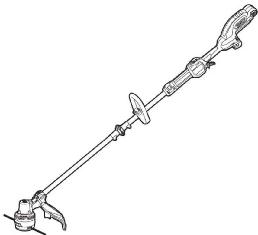
ST1610E-T
56 1-107n7oD y 1in7x uin DIA HE
56 1-2y