
V6320X2GB - Tumble dryer NEFF - Free user manual and instructions
Find the device manual for free V6320X2GB NEFF in PDF.
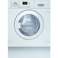



| Product type | Condensation dryer |
| Dimensions (H x W x D) | 84.5 x 60 x 60 cm |
| Weight | 45 kg |
| Power supply | 220-240 V, 50 Hz, 10 A |
| Load capacity | 8 kg |
| Main functions | Drying programs (Cotton, Synthetics, Mix, etc.), Delayed start, Anti-crease, Automatic drying with humidity sensor |
| Maintenance and cleaning | Clean the lint filter after each cycle, Empty the water tank, Clean the heat exchanger periodically |
| Safety | Child lock, Door safety, Overheat protection, Automatic shutdown in case of malfunction |
| Spare parts and repairability | Control panel, Front panel, Door, Door gasket, Door lock, Door hinge, Base cover. Parts available from customer service. |
| General information | Brand NEFF, Model V6320X2GB, repair manual available on notice-facile.com |
Frequently Asked Questions - V6320X2GB NEFF
User questions about V6320X2GB NEFF
0 question about this device. Answer the ones you know or ask your own.
Ask a new question about this device
Download the instructions for your Tumble dryer in PDF format for free! Find your manual V6320X2GB - NEFF and take your electronic device back in hand. On this page are published all the documents necessary for the use of your device. V6320X2GB by NEFF.
USER MANUAL V6320X2GB NEFF
SYMBOLS FOR DANGER AND SYMBOLS FOR IMAGES, WHICH GIVE INDICATION FOR THE TYPE OF DANGER.
In this document the following symbols for danger are used:
Mounting the heater.

Repair
4.2 Signal from the base channel
Checking:
Turn off the power supply. Turn off the circuit breaker.
4.2.1 Connecting the base channel
1. Screw in the screws.
2. Place the base of the channel and tighten the base of the channel downwards.
4.2.2 Mounting the base channel
Mounting the heater.

Repair
4.3 Changing the fuse
Checking:
The device is switched off. The device is disconnected from the mains. The primary circuit is disconnected. The control panel is disconnected. The door is closed. The door seal is closed. The base cover is closed.
4.3.1 Disconnect the primary circuit

CAUTION
Sharp edges on the housing!
Risk of injury
Wear protective gloves.
1.


CAUTION
Risk of falling parts due to loose screws! Risk of injury from falling parts.
Secure the component so that it does not fall.

WARNING!
Risk of falling parts due to loose screws!
The device is installed in the home and the client, see Fig. 1.
Secure the components so that they do not fall.
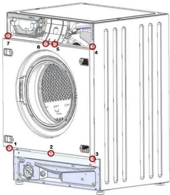
Remove the screws in sequence (1-2-3-4-5-6-7).
2. Installation
4.3.2 Mounting the device
Mounting the device.

Repair
4.4 Replacing the door
Removal:
The screws are removed from the locking mechanism. The device is disconnected from the water supply.
4.4.1 Removing the door
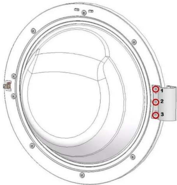
Remove the three screws.
4.4.2 Mounting the door
Mount the device.

Repair
4.5 Replacing the door seal


CAUTION
Sharp edges on the housing
HapaRaBaHnO Tnpa3BaHe
Hocete npednaa3n pkbauu.


BHMMATEIHO
Pnck O T npaun yactn npapn pa3xna6eHn BnHTOBe!
HapahBaHe npaui nadaun yactn.
3akpenete KOMnoHEHTa, Taka Ye da He naHe.

BHIMAHINE!
Pnck OT nadaaun yactn nopadn pa3xa6eHN BnHTOBe!
IobpeHa npytn Yactn Ha ypeHa nn B doma Ha knneHta, Hap. bHo
TO.
3akpeneTe KOMnoHEHTa, Taka Ye da He naHe.
N3nCKBaHe:
YpeDbTe N3KJIIOUeH OT 3aXpaHbAHeTO. YpeBt E N3KJIoueH OT BOOChA6DnTeHnHaT MaPexa
4.5.1 Cbajhe Ha ynnbTHEHnTo HA Bpata


BHMMATEIHO
Risk of falling parts when unscrewing screws!
Press down on the part.
Secure the component so that it does not fall.

WARNING!
Risk of falling parts when unscrewing screws!
Damage to the part or the tool or the clamp, e.g., due to
that.
Secure the component so that it does not fall.
1. Remove the cover for the first preparation. 2. Remove the control panel (two screws from the rear side and three screws in the 30- area of the preparation compartment). 3. REMOVE THE DOOR.
4. Remove the base cover.
5.

WARNING!
Risk of surface damage!
The surface of the tool may be scratched if you use incorrect tools.
Use only the specified tools for removal and installation.
Remove the seal from the filter and replace it with a new plastic seal.
- Removal

Repair
7. Loosen the filter connection with the hose for draining.
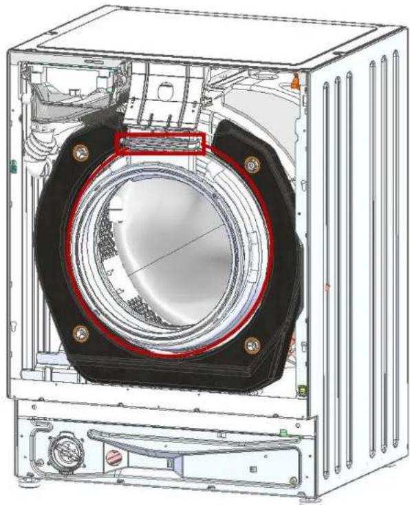
8. Remove the fixing screws of the filter on the drum flange (7 mm wrench). 9. Remove the filter.
Install the new filter.

Repair
4.6 Replacing the door lock
Requirements:
Disconnect the appliance from the power supply. Disconnect it from the water supply.
4.6.1 Removing the door lock
- Open the door.
2.

WARNING!
Risk of damaging the surface!
NoBpbxHcCTTa HyapeJaMoKeJa ce HAppacka, aKo N3non3BaTe HENPAJIINNHNCTpyMeHTN.
3non3BaIte cmo nactmacOBn HcTpyMeHTN.
N3BaTe npyKHHata n 136yTaIeYnTbTHHeHneTo.
3.CBaJIeTe BnHTOBeTe Ha KInOCHaNKaTa HA BpaTata. 4.Ocbo6oJeTe KIOHAnKaTa Ha BpaTata. 5. ⅢBaTe MexaHn3Ma 3a abapuHo OcBo6xDaBaHe Harope ot BoDauHa. 6.ИЗКПЮЧЕТКОЕТОРаHaKaбета.
4.6.2 MoThnpaHe Ha KInouaNkata Ha BpaTaTa
KNoHankataHaBpataTpr6BaDaEBnpaBnHTo nONOKeHHe,3a da OcNpynФyHKUra 3a ABapuHOOTbApAHe Ha BpataHa ypeda.
MoHTnpaTBeBobpaTeHpeI.

PemOH
4.7CMraHa Ha naHTata Ha BpaTaTa
BHIMATEJIHO
OTBOpTe 06nactTa Ha naHTnte!
Ppema3BaHe/3axBaUaHHe Hn pbcTNTe He nocaire Te KbM oBnaCTTa Ha naHTnte. HocTe npedna3n pbkabu.
N3NCKBaHe:
YpeBte n3KNIOUeHOT 3aXpaHbHeTo. YpeBte H3KNIOueHOT BOOCHaDNTenHaTa Mpeka. Me6eHnT nAHen eCBaHn. YeKMeDKeTo 3a nepnHnI npenapat e cBaIeHO. KoHTpOJIHnT nAHeI e CBAJIeH. Bparatae cbaneha. YnnbTheHneto Ha BpaTatae cBaJeHO, PpeHnT nHaen e cBaneH.
4.7.1 CBaJaHe Ha naHTaTa Ha BpaTaTa
1. CBane DaTa BnHTa.
- Cbane nata Hb pataTa.
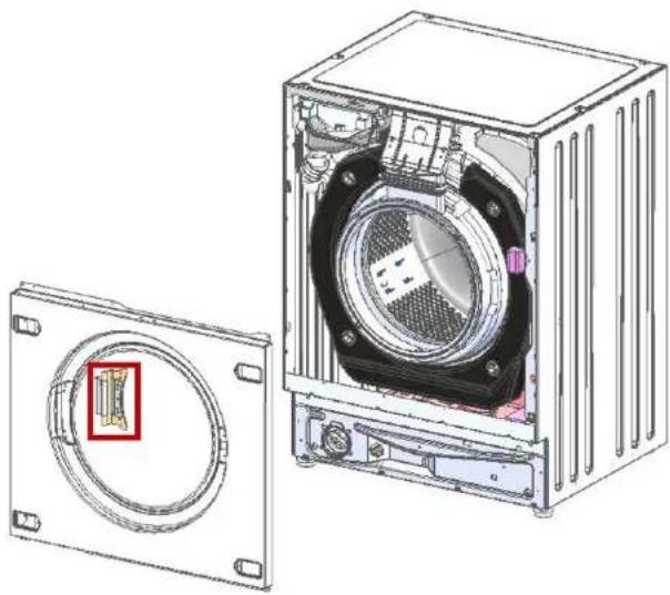
4.7.2 Mounting of the door panel
Mounting is done in reverse order.
4.3 Replacement of front panel
Presetting:
Make sure to secure the component against falling.

NOTE!
Risk of falling parts due to loose screws!
Make sure to secure the component against falling.
Presetting:

Make sure to secure the component against falling.

NOTE!
Risk of falling parts due to loose screws!
Make sure to secure the component against falling.
- Remove the detergent drawer.
- Remove the control panel (two screws on the rear side and four screws in the dispenser area).
- Remove the door.
- Remove the plinth cover.
5.

NOTE!
Repair hints - Washing machine
1 Concerning this document. 73
1.1 Important information 73
1.1.1 Purpose 73
1.2 Explanation of symbols 73
1.2.1 Danger levels.. 73 1.2.2 Hazard symbols 73 1.2.3 Structure of the warnings 74 1.2.4 General symbols 74
Safety. 75
2.1 General Safety instructions 75
2.1.1 All domestic appliances 75
Tools and aids. 76
Repair 77
4.1 Replacing control panel 77
4.1.1 Removing control panel 77 4.1.2 Installing control panel 78
4.2 Replacing base cover 79
4.2.1 Removing base cover 79 4.2.2 Installing base cover 79
4.3 Replacing front panel 80
4.3.1 Removing front panel 80 4.3.2 Installing front panel 80
Concerning this document
1.1 Important information
1.1.1 Purpose
These repair hints support consumers to repair appliances by themselves according to the applicable eco-design regulation (as of 03/2021).
They contain information on how to exchange defined spare parts, including warnings and risks.
In case of questions, please contact our customer service. We will only be liable for damages if the repair hints have been followed properly.
1.2 Explanation of symbols
1.2.1 Danger levels
The warning levels consist of a symbol and a signal word. The signal word indicates the severity of the danger.
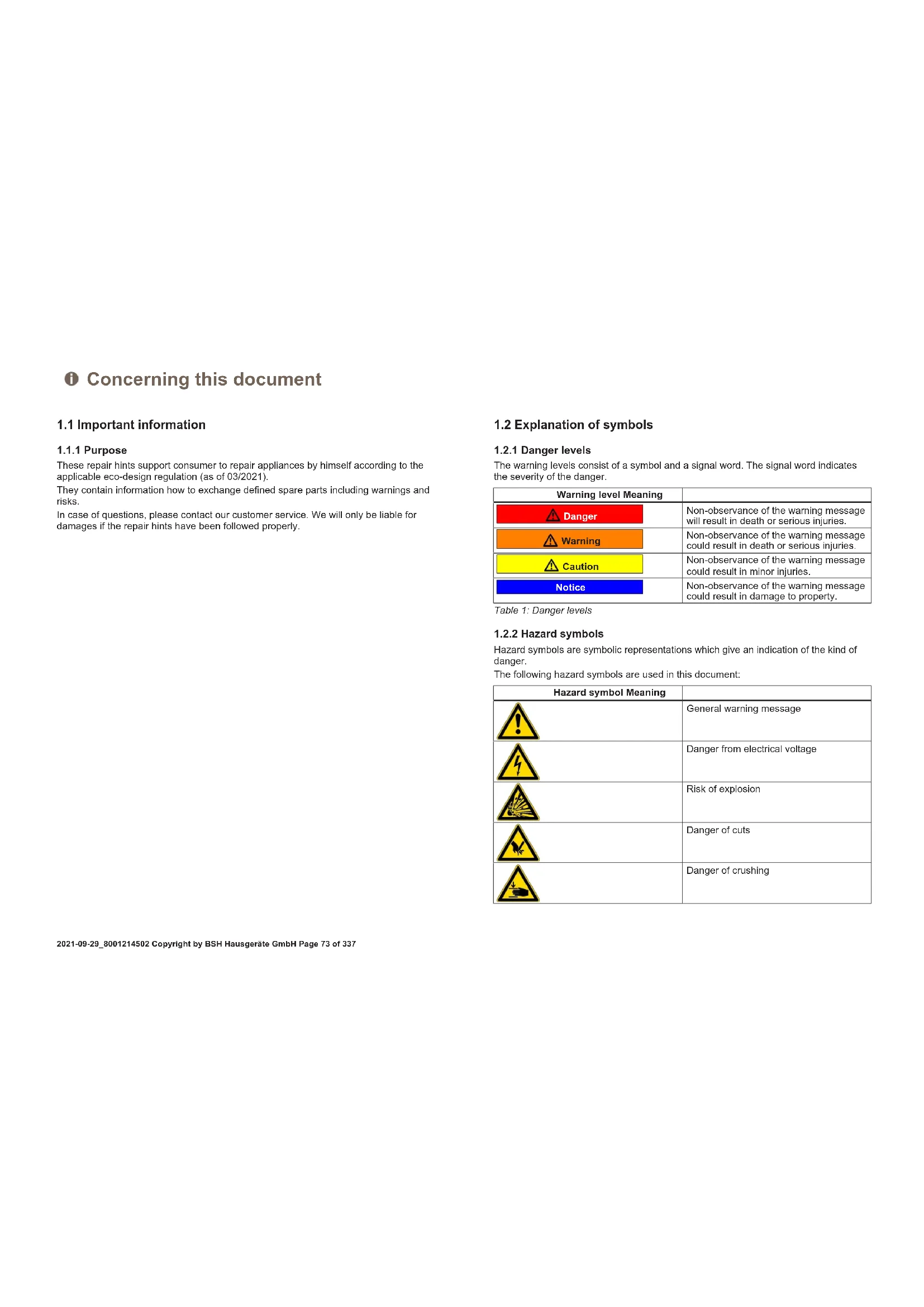
Table 1: Danger levels
| Warning level Meaning | |
| Danger | Non-observation of the warning message will result in death or serious injuries. |
| Warning | Non-observation of the warning message could result in death or serious injuries. |
| Caution | Non-observation of the warning message could result in minor injuries. |
| Notice | Non-observation of the warning message could result in damage to property. |
1.2.2 Hazard symbols
Hazard symbols are symbolic representations which give an indication of the kind of danger.
The following hazard symbols are used in this document:
| Hazard symbol Meaning | |
| ! | General warning message |
| Danger from electrical voltage | |
| Risk of explosion | |
| Danger of cuts | |
| Danger of crushing |
Concerning this document
| Hazard symbol Meaning | |
| Danger from hot surfaces | |
| Danger from strong magnetic field | |
| Danger from non-ionizing radiation |
Table 2: Hazard symbols
1.2.3 Structure of the warnings
Warnings in this document have a standardised appearance and a standardised structure.
Danger
Type and source of danger!
Possible consequences of ignoring the danger / warning.
Measures and prohibitions for preventing the danger.
The following example shows a warning that warns against electric shock due to live parts. The measure for avoiding the danger is mentioned.
Danger
Risk of electric shock due to live parts!
Death by electrocution
- Disconnect appliances from electrical supply at least 60 seconds before starting repairs.
1.2.4 General symbols
The following general symbols are used in this document:
| Gen. symbol Meaning | |
| 1 | Identification of a special tip (text and/or graphic) |
| i | Identification of a simple tip (only text) |
| Identification of a link to a video tutorial |
| Gen. symbol Meaning | |
| Identification of required tools | |
| Identification of required preconditions | |
| Identification of a condition (if ..., then ...) | |
| Identification of a result | |
| [Start]Identification of a key or button | |
| [00123456] Identification of a material number | |
| Status Identification of displayed text / window(in the appliance's display) | |
Table 3: General symbols
Safety
2.1 General Safety instructions
2.1.1 All domestic appliances
Risk of electric shock due to live parts!
Errors by repairs involving electrical components can lead to electrical shock! - Disconnect the appliance from the mains for at least 60 seconds before starting work. After the repair have a safety test according VDE 0701 or country-specific regulations performed.
Risk of injury from sharp edges!
Wear protective gloves.
Risk of crushing during repair, maintenance, troubleshooting and service due to heavy and moving components
Wear protective shoes. - Secure heavy components from falling down. - Do not stick body parts into moving components.
Risk to the appliance's safety / function! Only use original spare parts.
Risk of damage to electrostatically sensitive components (ESDs)! - Do not touch the modules, including connections and conductor paths.

Tools and aids
| Designation Details Images | ||
| Auxiliary tool [15000155] | Tool for loosening out of plastic parts | |
| Screwdriver Torx T20 with bore hole [00340764] | 100 mm, for screws with safety pin | |
| Torque spanner [15000441] | Torque spanner 20 - 100 Nm | |
| Slot screwdriver [00340854] | Blade 3.5 mm x 0.6 mm x 100 mm, Protective Insulation 1000 V AC | |
| Slot screwdriver [00340855] | Blade 5.5 mm x 1.0 mm x 125 mm, Protective Insulation 1000 V AC | |
| Needle-nose pliers, angled pattern [00341269] | Length 200 mm | |
| Side-cutting pliers [00342182] | Length: 200 mm | |
| Designation Details Images | ||
| Combination wrench [00340811] | Wrench size 10°mm, M6 | |
| Combination wrench [00340814] | Wrench size 13°mm, M8 | |
| Combination wrench [00340817] | Wrench size 17 mm, M10 | |
| Combination wrench [15000459] | Wrench size 16°mm, M10 | |

Repair
4.1 Replacing control panel
Prerequisite:
Appliance is disconnected from power supply. Appliance is disconnected from water supply. Furniture panel has been removed.
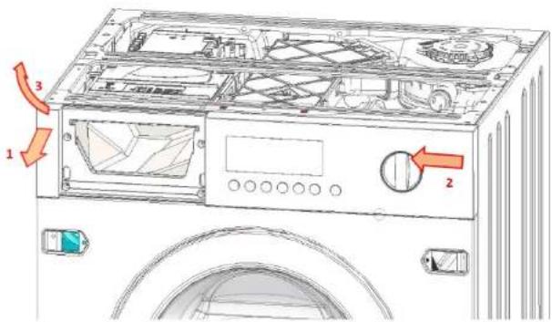
4.1.1 Removing control panel
- Remove detergent drawer.
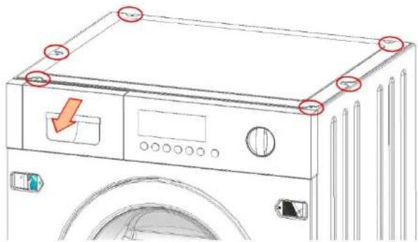
- Remove screws on metallic worktop and this last one.
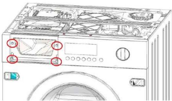
- Remove the screws on control panel (1-2-3-4).

Repair
- Grab control panel with hands on left and right side.
- Slightly pull out control panel on left side (1).
- Slightly push control panel to the left (2).
- Lift control panel to the front and upwards (3).
4.1.2 Installing control panel
Install in reverse order.

Repair
4.2 Replacing base cover
Prerequisite:
Appliance is disconnected from power supply. Appliance is disconnected from water supply.
4.2.1 Removing base cover
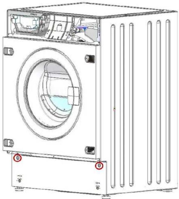
- Remove screws.
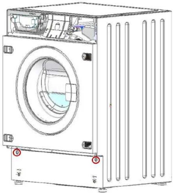
- Remove cover base by rotating base downward.
4.2.2 Installing base cover
Install in reverse order.

Repair
4.3 Replacing front panel
Prerequisite:
The appliance is disconnected from the power supply. The appliance is disconnected from the water supply. The detergent drawer has been removed. The control panel has been removed. The door has been removed. The door seal has been removed. The base cover has been removed.
4.3.1 Removing front panel

1.


Caution
Risk of falling parts due to released screws!
Injury because of falling parts. Secure the component from falling down.

Notice
Risk of falling parts due to released screws!
Damage to other parts of the appliance or at the customer's home, e.g., the bottom.
- Secure the component from falling down.
Remove screws in the following order (1-2-3-4-5-6-7).
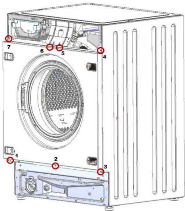
- Remove front panel.
4.3.2 Installing front panel
Install in reverse order.

Repair
4.4 Replacing door
Prerequisite:
Appliance is disconnected from power supply. Appliance is disconnected from water supply.
4.4.1 Removing door
Remove three screws.
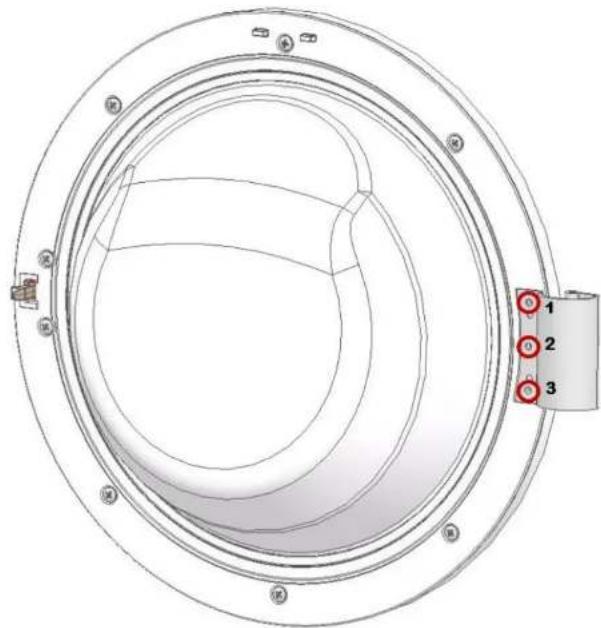
Install in reverse order.

Repair
4.5 Replacing door seal

Caution
Sharp housing edges! Cut injuries. Wear protective gloves.

Caution
Risk of falling parts due to released screws!
Injury because of falling parts. - Secure component from falling down.
Notice
Risk of falling parts due to released screws! Damage to other parts of the appliance or at customer's home, e.g., bottom. - Secure component from falling down.
Prerequisite:

Appliance is disconnected from power supply.

Appliance is disconnected from water supply.
4.5.1 Removing door seal

Caution
Risk of falling parts due to released screws! Injury because of falling parts. Secure component from falling down.
Notice
Risk of falling parts due to released screws!
Damage to other parts of the appliance or at customer's home, e.g., bottom.
Secure component from falling down.
Secure component from falling down.
- Remove detergent drawer.
- Remove control panel (two screws on right side and four screws on dispenser area).
- Remove door.
4. Remove base cover.


Notice
Risk of damaged surface!
Surface of appliance can be scratched by using wrong. Only use plastic tools to replace the tension ring.
Remove tension ring from gasket on front panel with a plastic tool.
6. Remove front panel.

Repair
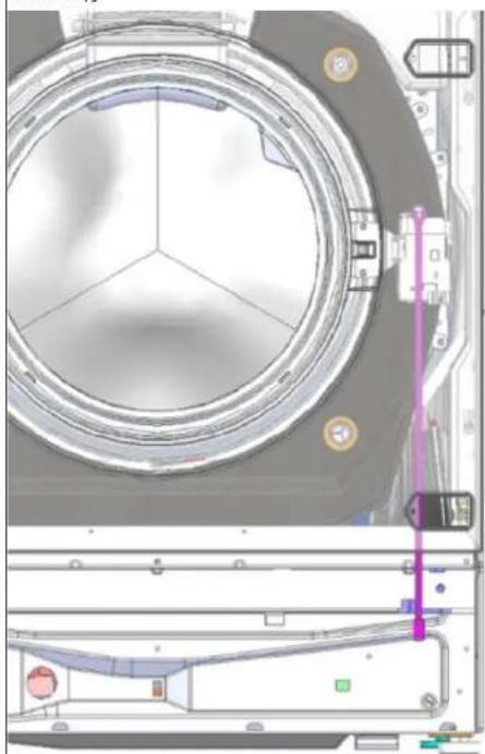
- Release gasket connection with dryer tunnel.
8. Remove fixation ring of gasket on plastic tub (7 mm socket wrench) 9. Remove gasket.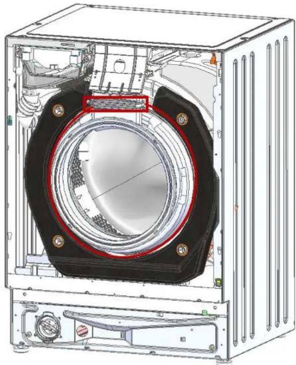
Install in reverse order.

Repair
4.6 Replacing door lock
Prerequisite:
The appliance is disconnected from the power supply. The appliance is disconnected from the water supply.
4.6.1 Removing door lock
- Open front door.
2

Notice
Risk of damaged surface!
The surface of the appliance can be scratched by using wrong tools.
Only use plastic tools.
Remove spring and push away seal.
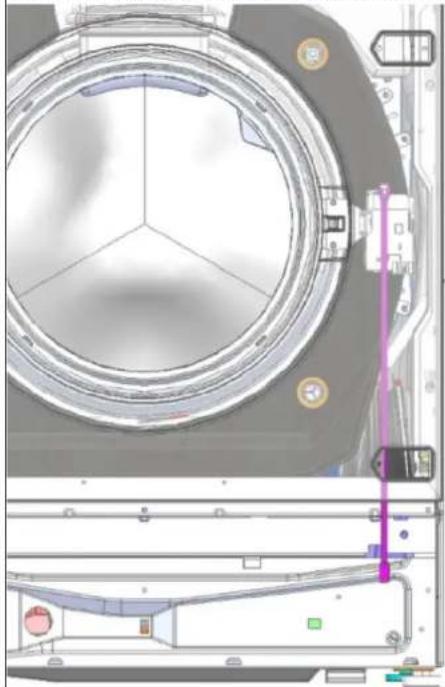
- Remove screws on door lock.
- Release door lock.
- Remove opening line upwards form guide.
- Disconnect cable connector.
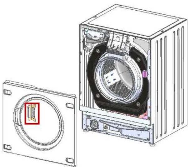
Door lock must be in the right position to ensure the emergency door opening function of the appliance.
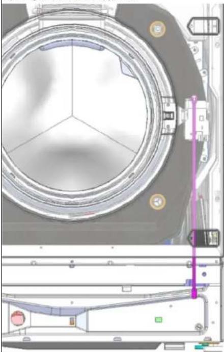
Install in reverse order.

Repair
4.7 Replacing door hinge

Open hinge area!
Finger crushing / entrapment Do not reach into the hinge area. Wear protective gloves.
Prerequisite:
Appliance is disconnected from power supply. Appliance is disconnected from water supply. Furniture panel has been removed. Detergent drawer has been removed. Control panel has been removed. Door has been removed. Door seal has been removed. Front panel has been removed.
- Remove two screws.
- Remove door hinge.
Install in reverse order.
Safety. 89
2.1 General safety instructions 89 2.1.1 Kitchen appliances 89
Table 1: Safety devices
1.2.2 Safety symbols
1. Avoid improper transport
2.
DANGER
The appliance can be used by children aged from 8 years and above and persons with reduced physical, sensory or mental capabilities or lack of experience and knowledge if they have been given supervision or instruction concerning use of the appliance in a safe way and understand the hazards involved.
The appliance can be used by children aged from 8 years and above and persons with reduced physical, sensory or mental capabilities or lack of experience and knowledge if they have been given supervision or instruction concerning use of the appliance in a safe way and understand the hazards involved.
Use only original spare parts.
Remove the plug from the socket.
3. Remove the plug from the socket. 4. Disconnect the appliance from the mains. 5. Remove the plug from the socket if the appliance is not in use. 6. Follow the instructions for use.
4.6.2 Safety device location
The safety device must be located in such a way that it is accessible for the safe operation of the appliance.
Install the device.

REMOVAL
4.7 Removing the device
WARNING
Before removing or installing the device, disconnect the power supply. Wear protective gloves.
Do not touch the contents with your bare hands. Wear protective gloves.
Procedure:
The device is disconnected from the power supply. The device is disconnected from the water supply. Check for water leakage. No water leakage. The drain hose is disconnected. The power cord is unplugged. No water in the drum. The filter is removed.
4.7.1 Removing the drain hose
- Remove two screws.
- Remove the drain hose.
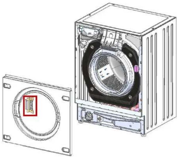
4.7.2 Installing the drain hose
Install the device.
- Remove the front panel.
4.3.2 Install the front panel


- REPAIR
- SIGNAL FROM THE BASE CHANNEL
- CONNECTING THE BASE CHANNEL
- MOUNTING THE BASE CHANNEL
- CHANGING THE FUSE
- DISCONNECT THE PRIMARY CIRCUIT
- CAUTION
- WARNING
- MOUNTING THE DEVICE
- REPLACING THE DOOR
- REMOVING THE DOOR
- MOUNTING THE DOOR
- REPLACING THE DOOR SEAL
- BHMMATEIHO
- BHIMAHINE
- N3NCKBAHE
- CBAJHE HA YNNBTHEHNTO HA BPATA
- REPLACING THE DOOR LOCK
- REMOVING THE DOOR LOCK
- MOTHNPAHE HA KINOUANKATA HA BPATATA
- PEMOH
- CMRAHA HA NAHTATA HA BPATATA
- BHIMATEJIHO
- CBAJAHE HA NAHTATA HA BPATATA
- MOUNTING OF THE DOOR PANEL
- REPLACEMENT OF FRONT PANEL
- NOTE
- PRESETTING
- REPAIR HINTS - WASHING MACHINE
- CONCERNING THIS DOCUMENT
- IMPORTANT INFORMATION
- PURPOSE
- EXPLANATION OF SYMBOLS
- DANGER LEVELS
- HAZARD SYMBOLS
- STRUCTURE OF THE WARNINGS
- DANGER
- GENERAL SYMBOLS
- SAFETY
- GENERAL SAFETY INSTRUCTIONS
- ALL DOMESTIC APPLIANCES
- TOOLS AND AIDS
- REPLACING CONTROL PANEL
- PREREQUISITE
- REMOVING CONTROL PANEL
- INSTALLING CONTROL PANEL
- REPLACING BASE COVER
- REMOVING BASE COVER
- INSTALLING BASE COVER
- REPLACING FRONT PANEL
- REMOVING FRONT PANEL
- NOTICE
- INSTALLING FRONT PANEL
- REPLACING DOOR
- REMOVING DOOR
- REPLACING DOOR SEAL
- REMOVING DOOR SEAL
- REMOVE BASE COVER
- REMOVE FRONT PANEL
- REPLACING DOOR LOCK
- REMOVING DOOR LOCK
- REPLACING DOOR HINGE
- OPEN HINGE AREA
- SAFETY SYMBOLS
- SAFETY DEVICE LOCATION
- REMOVAL
- REMOVING THE DEVICE
- PROCEDURE
- REMOVING THE DRAIN HOSE
- INSTALLING THE DRAIN HOSE
- INSTALL THE FRONT PANEL
Brand : NEFF
Model : V6320X2GB
Category : Tumble dryer