
SE 12115 - Polisher METABO - Free user manual and instructions
Find the device manual for free SE 12115 METABO in PDF.
| Brand | Metabo |
| Model | SE 12115 |
| Product type | Polisher / Satinizer |
| Power supply | Mains (230 V, 50 Hz) |
| No-load speed | 900 - 2810 rpm (adjustable in 6 positions) |
| Rated input power | Not specified in the manual |
| Compatible materials | Metal, wood, plastics and similar |
| Main functions | Polishing, satinizing, brushing, sanding, deburring |
| Included accessories | Collet chuck, fork wrench, spacer sleeves |
| Protective guard | Yes, included |
| Additional handle | Yes, adjustable |
| Switch | Sliding with continuous-run function |
| Spindle lock | Yes, for accessory change |
| VTC electronics | Speed maintenance under load |
| Restart protection | Yes (electronic indicator) |
| Motor cleaning | Blow compressed air through the ventilation slots |
| Brush maintenance | Autostop carbon brushes, replacement by specialized workshop |
| Weight | Not specified in the manual |
| Dimensions | Not specified in the manual |
| Compliance | European directives (see declaration) |
Frequently Asked Questions - SE 12115 METABO
User questions about SE 12115 METABO
0 question about this device. Answer the ones you know or ask your own.
Ask a new question about this device
Download the instructions for your Polisher in PDF format for free! Find your manual SE 12115 - METABO and take your electronic device back in hand. On this page are published all the documents necessary for the use of your device. SE 12115 by METABO.
USER MANUAL SE 12115 METABO
S 18 LTX 115 SE 12-115
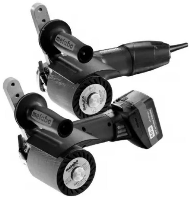

18 V...3,0 Ah 6.25594
18 V...4,0 Ah 6.25591
18 V...5,2 Ah ... 6.25592
etc.
| 17 | S 18 LTX 115 SE 12-115 *1) Serial Number: 00154...*1) Serial Number: 02115... | ||
| D mm (in) | 100 - 200 (4 - 8) | ||
| Bmax | mm (in) | 50 - 100 (2 - 4) | |
| M / I - / mm (in) | M 14 (5/8" - 11 UNC) / 20 (25/32) | ||
| n min | -1 (rpm) | 3000 900 - 2810 | |
| UV | 18 | - | |
| P1 | W | - 1200 | |
| P2 | W | - 720 | |
| m kg (lbs) | 3,1 (6.8) 3,0 (6.6) | ||
| ah,p/Kh,p | m/s2 | <2,5/1,5<2,5/1,5 | |
| LpA/KpA | dB(A) | 79/386/3 | |
| LWA/KWA | dB(A) | 90/397/3 | |
CE^*2) 2004/108/EC (->19.04.2016) /2014/30/EU (20.04.2016 ->), 2006/42/EC, 2011/65/EU ^ 3 EN 60745-1:2009+A11:2010, EN 60745-2-3:2011+A2:2013

Original instructions
1. Declaration of Conformity
We declare under our sole responsibility: These burnishing machines, identified by type and serial number 1 , comply with all relevant requirements of the directives 2 and standards 3 . Technical file at 4 - see page 3.
2. Specified Use
The burnishing machine is suitable
for burnishing, matting, texturing and brushing,
for polishing and smoothing,
- for sanding and deburring the following materials:
metal, wood, plastics and similar
The user bears sole responsibility for any damage caused by improper use.
Generally accepted accident prevention regulations and the enclosed safety information must be observed.
3. General safety instructions

For your own protection and for the protection of your power tool, pay attention to all parts of the text that are marked with this symbol!

WARNING - Reading the operating instructions will reduce the risk of injury.

WARNING Read all safety warnings and instructions. Failure to follow all safety warn
ings and instructions may result in electric shock, fire and/or serious injury.
Keep all safety instructions and information for future reference.
Pass on your electrical tool only together with these documents.
4. Special Safety Instructions
4.1 SafetyWarnings Common for Grinding, Sanding, Wire Brushing, Polishing or Abrasive Cutting-Off Operations:
a) This power tool is intended to function as a sander, wire brush or polisher. Read all safety warnings, instructions, illustrations and specifications provided with this power tool. Failure to follow all the instructions may result in electric shock, fire and/or serious injury.
b) Operations such as grinding or cutting-off are not recommended to be performed with this power tool. Operations for which the power tool was not designed may create a hazard and cause personal injury.
c) Do not use accessories which are not specifically designed and recommended by the tool manufacturer. Just because the accessory can be attached to your power tool, it does not assure safe operation.
d) The rated speed of the accessory must be at least equal to the maximum speed marked on the power tool. Accessories running faster than their rated speed can break and fly apart.
e) The outside diameter and the thickness of your accessory must be within the capacity rating of your power tool. Incorrectly sized accessories cannot be adequately guarded or controlled.
f) The arbour size of wheels, flanges, backing pads or any other accessory must properly fit the spindle of the power tool. Accessories with arbour holes that do not match the mounting hardware of the power tool will run out of balance, vibrate excessively and may cause loss of control.
g) Do not use a damaged accessory. Before each use, inspect accessories such as abrasive wheels for chips and cracks, backing pad for cracks, tear or excess wear, wire brush for loose or cracked wires. If a power tool or accessory is dropped, inspect for damage or install an undamaged accessory. After inspecting and installing an accessory, position yourself and bystanders away from the plane of the rotating accessory and run the power tool at maximum no-load speed for one minute. Damaged accessories will normally break apart during this test time.
h) Wear personal protective equipment. Depending on application, use a face shield, safety goggles or safety glasses. As appropriate, wear dust mask, hearing protectors, gloves and workshop apron capable of stopping small abrasive or workpiece fragments.
The eye protection must be capable of stopping flying debris generated by various operations. The dust mask or respirator must be capable of filtering particles generated by your operation. Prolonged exposure to high intensity noise may cause hearing loss.
i) Keep bystanders a safe distance away from work area. Anyone entering the work area must wear personal protective equipment. Fragments of workpiece or of a broken accessory may fly away and cause injury beyond immediate area of operation.
j) Hold power tool by insulated gripping surfaces only, when performing an operation where the cutting accessory may contact hidden wiring or its own cord. Cutting accessory contacting a "live" wire may make exposed metal parts of the power tool "live" and shock the operator.
k) Position the cord clear of the spinning accessory. If you lose control, the cord may be cut or snagged and your hand or arm may be pulled into the spinning accessory.
1) Never lay the power tool down until the accessory has come to a complete stop. The spinning accessory may grip the surface and pull the power tool out of your control.
m) Do not run the power tool while carrying it at your side. Accidental contact with the spinning
accessory could snag your clothing, pulling the accessory into your body.
n) Regularly clean the power tool's air vents. The motor's fan will draw the dust inside the housing and excessive accumulation of powdered metal may cause electrical hazards.
o) Do not operate the power tool near flammable materials. Sparks could ignite these materials.
p) Do not use accessories that require liquid coolants. Using water or other liquid coolants may result in electrocution or shock.
4.2 Kickback and RelatedWarnings
Kickback is a sudden reaction to a pinched or snagged rotating wheel, backing pad, brush or any other accessory. Pinching or snagging causes rapid stalling of the rotating accessory which in turn causes the uncontrolled power tool to be forced in the direction opposite to the accessory's rotation at the point of jamming.
For example, if an abrasive wheel is snagged or pinched by the workpiece, the edge of the wheel that is entering into the pinch point can dig into the surface of the material causing the wheel to climb out or kick out. The wheel may either jump toward or away from the operator, depending on direction of the wheel's movement at the point of pinching. Abrasive wheels may also break under these conditions.
Kickback is the result of power tool misuse and/or incorrect operating procedures or conditions and can be avoided by taking proper precautions as given below.
a) Maintain a firm grip on the power tool and position your body and arm to allow you to resist kickback forces. Always use additional handle, if provided, for maximum control over kickback or torque reaction during start-up.
The operator can control torque reactions or kickback forces, if proper precautions are taken.
b) Never place your hand near the rotating accessory. Accessory may kickback over your hand.
c) Do not position your body in the area where power tool will move if kickback occurs. Kickback will propel the tool in direction opposite to the wheel's movement at the point of snagging.
d) Use special care when working around corners, sharp edges etc. Avoid bouncing and snagging the accessory. Corners, sharp edges or bouncing have a tendency to snag the rotating accessory and cause loss of control or kickback.
e) Do not attach a saw chain woodcarving blade or toothed saw blade. Such blades create frequent kickback and loss of control.
4.3 SafetyWarnings Specific for Sanding Operations:
a) Do not use oversized sanding disc paper. Follow manufacturer's recommendations when selecting sanding paper. Larger sanding paper
extending beyond the sanding pad presents a laceration hazard and may cause snagging, tearing of the disc or kickback.
4.4 SafetyWarnings Specific for Polishing: Loose parts on the polishing guard, especially the fastening cords, are not permitted. Tuck away or shorten the fastening cords. Loose, spinning fastening cords may make contact with your fingers or become caught in the workpiece.
4.5 SafetyWarnings Specific for Wire Brushing Operations:
a) Be aware that wire bristles are lost by the brush even during ordinary operation. Do not overstress the wires by applying excessive load to the brush. The wire bristles can easily penetrate light clothing and/or skin.
b) If the use of a safety guard is recommended for wire brushing, do not allow any interference of the wire wheel or brush with the guard. Wire wheel or brush may expand in diameter due to work load and centrifugal forces.
4.6 Additional Safety Instructions

WARNING - Always wear protective goggles.
Use elastic cushioning layers if they have been supplied with the abrasive and if required.
Observe the specifications of the tool or accessory manufacturer!
Accessories must be stored and handled with care in accordance with the manufacturer's instructions.
Ensure that accessories are installed in accordance with the manufacturer's instructions.
The tool continues running after the machine has been switched off.
When sanding and working with the sheepskin polishing disc with cord drive always work with the safety guard installed.
Do not use separate reducing bushings or adapters to adapt tools with a large hole.
The workpiece must lay flat and be secured against slipping, e.g. using clamps. Large workpieces must be supported adequately.
If accessories with threaded inserts are used, the end of the spindle may not touch the base of the hole on the grinding tool. Make sure that the thread in the accessory is long enough to accommodate the full length of the spindle. The thread in the accessory must match the thread on the spindle. See page 3 and chapter 14. Technical Specifications for more information on the spindle length and thread.
Dust from material such as paint containing lead, some wood species, minerals and metal may be harmful. Contact with or inhalation of the dust may cause allergic reactions and/or respiratory diseases to the operator or bystanders.
Certain kinds of dust are classified as carcinogenic, such as oak and beech dust, especially in
ENGLISHen
conjunction with additives for wood conditioning (chromate, wood preservative). Material containing asbestos must only be treated by specialists.
- Use a dust extraction device where possible.
- The work place must be well ventilated.
- The use of a dust mask of filter class P2 is recommended.
Follow national requirements for the materials you want to work with.
Materials that generate dusts or vapours that may be harmful to health (e.g. asbestos) must not be processed.
When working in dusty conditions, ensure that ventilation openings are not blocked. If it becomes necessary to remove dust, first disconnect the power tool from the mains supply (use non-metallic objects) and avoid damaging internal components.
Damaged, eccentric or vibrating tools must not be used.
A damaged or cracked additional handle must be replaced. Never operate a machine with a defective additional handle.
Only use the machine if the safety guard is in place.
Always guide the machine with both hands on the handles provided
4.7 Reducing dust exposure:
WARNING - Some dust created by power sanding, sawing, grinding, drilling, and other construction activities contains chemicals known to cause cancer, birth defects or other reproductive harm. Some examples of these chemicals are:
- Lead from lead-based paints,
- Crystalline silica from bricks and cement and other masonry products, and
- Arsenic and chromium from chemically treated lumber.
Your risk from these exposures varies, depending on how often you do this type of work. To reduce your exposure to these chemicals: work in a well ventilated area, and work with approved safety equipment, such as those dust masks that are specially designed to filter out microscopic particles.
This also applies to dust from other materials such as some timber types (like oak or beech dust), metals, asbestos. Other known diseases are e.g. allergic reactions, respiratory diseases. Do not let dust enter the body.
Observe the relevant guidelines and national regulations for your material, staff, application and place of application (e.g. occupational health and safety regulations, disposal).
Collect the particles generated at the source, avoid deposits in the surrounding area.
Use suitable accessories for special work. In this way, fewer particles enter the environment in an uncontrolled manner.
Use a suitable extraction unit.
Reduce dust exposure with the following measures:
- do not direct the escaping particles and the exhaust air stream at yourself or nearby persons or on dust deposits,
- use an extraction unit and/or air purifiers,
- ensure good ventilation of the workplace and keep clean using a vacuum cleaner. Sweeping or blowing stirs up dust.
- Vacuum or wash the protective clothing. Do not blow, beat or brush.
4.8 Special safety instructions for mains powered machines:
Pull the plug out of the plug socket before any adjustments, conversions or servicing are performed.
Before connecting the mains plug, make sure that the machine is switched off.
During machining, of metals in particular, conductive dust can form deposits inside the machine. This can lead to the transfer of electrical energy onto the machine housing. This can mean a temporary danger of electric shocks. This is why it is necessary when the machine is running to blow compressed air through the rear ventilation slots of the machine regularly, frequently and thoroughly. Here, the machine must be held firmly.
We recommend using a stationary extractor system and connecting a residual current circuit-breaker (FI) upstream. When the machine is shut down via the FI circuit-breaker, it must be checked and cleaned. See chapter 9. Maintenance for more information on cleaning the motor.
4.9 Special safety instructions for cordless machines:
Remove the battery pack from the machine before any adjustments, conversions or servicing are performed.
Before fitting the battery pack, make sure that the machine is switched off.

Protect battery packs from water and moisture!
Do not expose battery packs to naked flame!

Do not use faulty or deformed battery packs!
Do not open battery packs!
Do not touch or short-circuit battery packs!
Slightly acidic, flammable fluid may leak from defective li-ion battery packs!
If battery fluid leaks out and comes into contact with your skin, rinse immediately with plenty of water. If battery fluid leaks out and comes into contact with your eyes, wash them with clean water and seek medical attention immediately.
If the machine is defective, remove the battery pack from the machine.
Transport of li-ion battery packs:
The shipping of li-ion battery pack is subject to laws related to the carriage of hazardous goods (UN 3480 and UN 3481). Inform yourself of the currently valid specifications when shipping li-ion battery
packs. If necessary, consult your freight forwarder. Certified packaging is available from Metabo.
Only send the battery pack if the housing is intact and no fluid is leaking. Remove the battery pack from the machine for sending. Prevent the contacts from short-circuiting (e.g. by protecting them with adhesive tape).
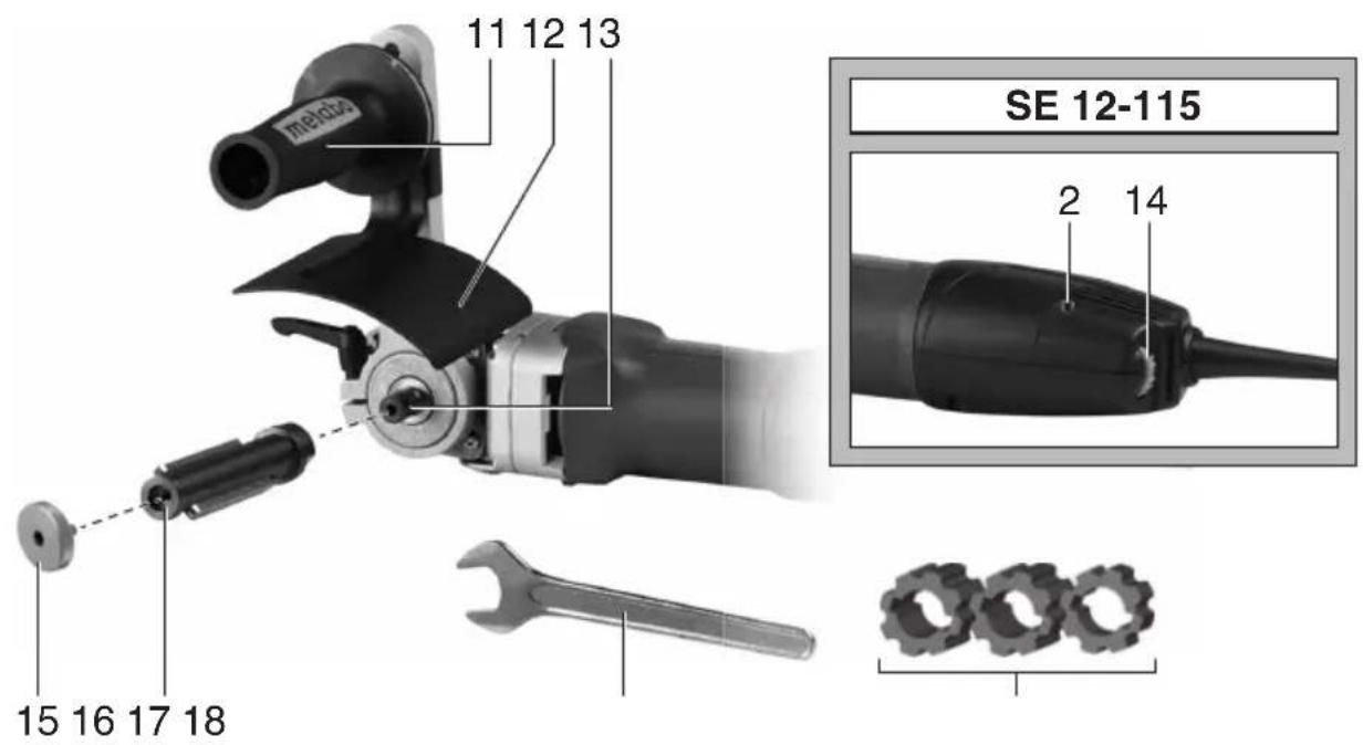
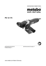
5. Overview
See page 2.
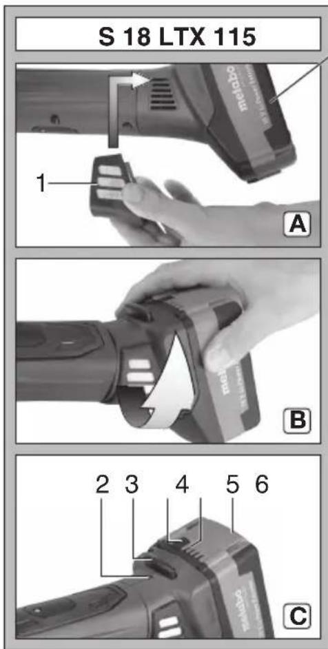
1 Dust filter (S 18 LTX 115)
2 Electronic signal indicator
3 Button to unlock battery pack (S 18 LTX 115)
4 Capacity indicator button (S 18 LTX 115)
5 Capacity and signal indicator (S 18 LTX 115)
6 Battery pack (S 18 LTX 115)
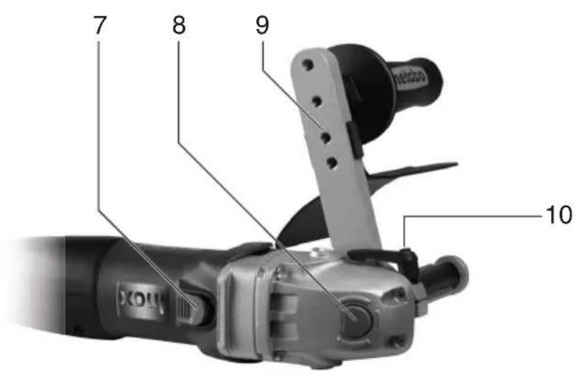
7 Sliding on/off switch
8 Spindle locking button
9 Handl e b a r
10 Clamping lever
11 Additional handle
12 Safety guard
13 Spindle
14 Speed adjustment wheel (SE 12-115)
15 Tool fixing screw
16 Tensioning spindle (with 2 captive fitted keys)
17 Open-ended spanner
18 Distance sleeves (for tools shorter than the tensioning spindle)
6. Initial Operation
Safety guard
As illustrated, screw the safety guard (12) with the additional handle (11) into one of the threaded holes of the handle bar (9). Keep the distance to the tool as short as possible. Tighten the additional handle by applying force.
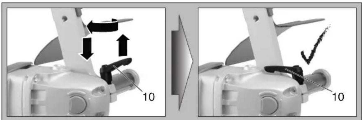
Handle bar
The handle bar (9) must be fitted as far as the limit stop on the gearbox flange.
After releasing the clamping lever (10), the handle bar (9) can be turned to the desired position. Firmly tighten the clamping lever (10) again. The position of the lever might need to be changed for this purpose.
The position of the lever can be changed without turning the clamping screw. For this purpose, raise the lever, turn it and then lower the lever again (see illustration, page 2).
When working, always position the lever in a way that it cannot come into contact with the tool.
Tensioning spindle
Screw the tensioning spindle (10) onto the spindle (4) while holding in the spindle locking knob (2) and tighten with an open-ended spanner (12).
6.1 For mains powered machines only Mains connection
Before plugging in the device, check that the rated mains voltage and mains frequency, as specified on the rating label, match your power supply.
The red electronics signal indicator (7) lights up briefly when the mains plug is inserted in the socket, indicating readiness for operation.
Setting speed
The speed can be preset via the setting wheel (14) and is infinitely variable.
Positions 1-6 correspond approximately to the following no-load speeds:
1 900 rpm 4 2050 rpm
2 1250 rpm 5 2410 rpm
3 1660 rpm 6 2810 rpm
The VTC electronics make material-compatible work possible and an almost constant speed, even under load.
The best way to determine the ideal speed setting is by performing a test.
6.2 For cordless machines only
Dust filter
Always fit the dust filter if the surroundings are heavily polluted (1).
The machine heats up faster when the dust filter is fitted (1). It is protected by the electronics system from overheating (see chapter10.).
Attaching: See page 2, illustration A.
Attach dust filter (1) as shown.
To remove: Holding the dust filter (1) by the upper edges, raise it slightly and then pull it downwards and remove.
Rotating battery pack
See illustration B on page 2.
The rear section of the machine can be rotated 270^ in three stages, thus allowing the machine's shape to be adapted to the working conditions. Only operate the machine when it is in an engaged position.
Battery pack
Charge the battery pack before use (6).
If performance diminishes, recharge the battery pack.
The ideal storage temperature is between 10^ and 30^ .
"Li-Power" li-ion battery packs have a capacity and signal indicator: (5)
- Press the button (4), the LEDs indicate the charge level.
- If one LED is flashing, the battery pack is almost flat and must be recharged.
ENGLISHen
Removing and inserting the battery pack
To remove: Press the battery pack release button (3) and pull the battery pack (6) downwards. To fit: Slide in the battery pack (6) until it engages.
7. Switching ON and OFF

Always guide the machine with both hands.

Switch on first, then guide the accessory towards the workpiece.

The machine must not be allowed to draw in additional dust and shavings. When switching
the machine on and off, keep it away from dust deposits. After switching off the machine, only place it down when the motor has come to a standstill.

In continuous operation, the machine continues running if it is forced out of your
hands. Therefore, always hold the machine with both hands using the handles provided, stand in a safe position and concentrate.
Switching on: Push the slide switch (7) forward.
For continuous activation, now tilt downwards until it engages.
Switching off: Press the rear end of the slide switch (7) and release.
8. Installing the tools

Press in the spindle locking knob (8) only when the spindle is stationary!
Tools with threaded insert:
- Remove the tensioning spindle (16) if necessary. Press in spindle locking button (8) and hold in place. Unscrew the tensioning spindle using the open-ended spanner (17).
- Press in spindle locking button and hold in place.
- Screw the tool onto the spindle and tighten.
Tools for tensioning spindle:
- Attach the tensioning spindle (16) if necessary. Press in spindle locking button (8) and hold in place. Tighten the tensioning spindle using the open-ended spanner (17).
- Slide the tool onto the tensioning spindle.
- Press in spindle locking button (8) and hold in place.
- Screw the tool fixing screw (15) onto the tensioning spindle and tighten (the spindle locking knob engages and the tool can be secured).

If the tools used are shorter than the tensioning spindle, insert the relevant distance
sleeves (18). This is the only way to properly secure the tool.
9. Maintenance
Disconnect the mains plug or remove the battery pack from the machine before starting any maintenance work.
Motor cleaning: blow compressed air through the rear ventilation slots of the machine regularly,
frequently and thoroughly. Here, the machine must be held firmly.
Mains powered machines: The Autostop carbon brushes must only be replaced in a specialist workshop. Always have checks and maintenance work carried out by Metabo Customer Service.
10. Troubleshooting
10.1 Mains powered machines
- Electronic restart protection
The red electronic signal indicator (2) starts flashing. If the mains plug is inserted with the machine switched on, or if the current supply is restored following an interruption, the machine does not start up. Switch the machine off and then back on again. - The electronic signal indicator (2) lights up and on-load speed is reduced.
Winding temperature too high. Run the machine in idling until the electronics signal indicator switches off. - High-energy, high-frequency interference
High-energy, high-frequency interference can cause the machine to deactivate. In this case, please switch off the machine, disconnect the plug and then reinsert. As soon as the interference is reduced, you can continue work.
10.2 Cordless machines
- The electronic signal display (2) lights up and the load speed decreases. The temperature is too high! Run the machine in idling until the electronics signal indicator switches off.
- The electronic signal display (2) flashes and the machine does not start. The restart protection is active. The machine will not start if the battery pack is inserted while the machine is on. Switch the machine off and on again.
11. Accessories
Use only original Metabo or CAS (Cordless Alliance System) battery packs and accessories.
Use only accessories that fulfil the requirements and specifications listed in these operating instructions.
For a complete range of accessories, see
www.metabo.com or the catalogue.
12. Repairs

Repairs to electrical tools must be carried out by qualified electricians ONLY!
If you have Metabo electrical tools that require repairs, please contact your Metabo service centre. For addresses see www.metabo.com.
You can download spare parts lists from www.metabo.com.
13. Environmental Protection
Observe national regulations on environmentally compatible disposal and on the recycling of disused machines, packaging and accessories.

Only for EU countries: Never dispose of power tools in your household waste! In accordance with European Directive 2012/
19/EU on used electronic and electric equipment and its implementation in national legal systems, used power tools must be collected separately and handed in for environmentally compatible recycling.
Special instructions for cordless machines:
Battery packs must not be disposed of with regular waste. Return faulty or used battery packs to your Metabo dealer!
Do not allow battery packs to come into contact with water!
Before disposal, discharge the battery pack in the power tool. Prevent the contacts from short-circuiting (e.g. by protecting them with adhesive tape).
LpA =Sound pressure level
Explanation of details on page 3. Subject to changes serving technical progress.
D = Permitted wheel diameter
Bmax =Maximum wheel width
M= S p i n d I e t h r e a d 1 = L e n g t h o f s p i r
n = No-load speed (maximum speed)
U = Voltage of battery pack
P1 =Nominal power input
P2 =Power output
m = Weight with smallest battery pack/weight without cord
Measured values determined in conformity with EN 60745.
Direct current (cordless machines)
Alternating current (mains powered machines)
Machine in protection class II (mains powered machines)
The technical specifications quoted are subject to tolerances (in compliance with the relevant valid standards).
A Emission values
Using these values, you can estimate the emissions from this power tool and compare these with the values emitted by other power tools. The actual values may be higher or lower, depending on the particular application and the condition of the tool or power tool. In estimating the values, you should also include work breaks and periods of low use. Based on the estimated emission values, specify protective measures for the user - for example, any organisational steps that must be put in place.
Vibration total value (vector sum of three directions) determined in accordance with EN 60745:
a_h, P = Vibration emission value (polishing)
K_h,P =Uncertainty (vibration)
Typical A-effective perceived sound levels:
FRANÇAISfr
Kh.D =Incertitude (vibration)
Transport van Li-ion-accupacks:
Programa completeness of accessories véase www.metabo.com o CATALOGO.
12. Reparación
M = R o s c a d I = C o m p r
Transport at Li-ion-batteripakker:
Transport at Li-ion-batteripakker:
Reservedelsestiner kan downloads paa www.metabo.com.
a_h, P = Vibrationsemission (polering)
K_h,P = Usikkerhed (vibration)
a) He nCnoJb3yIte 7nHΦNCTbI CnHkOM 6oJbWOrO pa3Mepa, npHepeHNBaHTecb 3aDaHHbIX 3HaueHn pa3MepOB JInCTOB.
IINΦNCTbI, BbICTyNaIOUne 3a KpaTapeLOK, MOrY CTaTb PnUHNO TpaBM, pa3OpBaTbcR, a TaKHe PpNBecTN K 3aJMy NIn K OTdaYe.
4.4 Oco6bIe yka3aHnno TeXnHe 6e30nac-HocTH npu wlnfoBaHH n HcNoJIb3OBAHHem HaJdaHOn 6yMaHn:
PpocleHte, TTo6bI He CBncaJIyactn noJIpOBAJIbHOro KOJINaHa, OcO6eHNo UHyPKN IJRAero KpeJIeHHa. Y6epHTe BCTOPHYIIIN 06peHbTe uHyPKN. CBncaIOUne H BpaUaIOuIuce npi paBoTe KOHcBi UHyPKOB MOryt HaMoTAtbCra Ha naJIbCuI INI 3aROTOBHy.
PYCCKHru
4.5 Oco6bIe yka3aHnno TeXnHe 6e3onac-HocTH nIpa60TbIC KapdouTeKamn:
a) HmeIte B BVdu, YTO n3 HapdoUeTHN BbINA daOT KycOuHN IpBOJOnH N npn OsbIyHOJ 3KcNlyatauH. He neperpyHaTe npoBOLKy n3JIuHHe BbICOKHM daBJIeHNem npHHMa.
OTleTaIOUe KycOuKN npOBOLOKMOrTy IerKo npOHKnHyTb CKB03b TOHkyO ODeJy NnN KoKy.
6) Ecnn peHomeHDoBaHO npHmEHeHne 3aunTHoro KOHyxa, He dOnychaIte CoPnHOcoHOBeHHra 3aunTHoro KOHyxa HapdoUeTHN.
IiAmEtP TapeJIbYaTbIX NHaIeUHbIX UTeTOK MoKET YBeIINuBaTbCn IOB O3JeNCTBnEM DaBLeHnI npHHMa n CEHTPo6eHHbIX CnI.
4.6 DoONHHTeJbHbIe yKa3aHnA NO TEXHnKe 6e3OnaCHOCTN:

PNEyPENKDEHNE-BceRda Hocnte 3aunTHbIe OUK.
B clyuayx, Tpe6yUoInx npIMeHHeNHaJIaCTnHbIX npOMeKHyTOUhBX 3JIeMeHTOB, HcNoJIb3yIte npOKlaIKN, NOCTaBJIeMbIe BMeCTe C INHCTpyMeHTOM.
Co6IIOdaIte yka3aHnna n3rOToBnteIra pa6oUnx HHCTpyMeHTOB nn npHaJNeXHOcTe!
XpaHnTb n npmEnrTa paOChn HcTpMeHTbl Heo6xOaIMO aKHypaTHo N B COOTBcTCTBn C ppeIINCAHNMI npOn3BOIDTeJI.
Y6eHITecb, YTO pa6OuNe HNCTpyMeHTbI yCTaHOBJIeHbIB COOTBETCTBnC INHCTpyKUJHM NpON3BOIDNTeJI.
IocJe BbIKNoeHnpa6OuN HNCTpyMeHT eUe HeKOTOpoe BpeMa pa6OtaT no INHePcun.
PnIuNFOBaHnIpa6oTe c nCNoJIb3OBAHNEMexOBOro NIOIpOBaJIbHOrO KOJINaKa CO UHypKOMBCERda yCTaHaBNIbaIte 3aUHTbI KOKyX.
IcnoJb3OBAtB OTdJIbHbIe nepExoHbIe BTyIKN IIN aAnTepbl B CEJIAX NOIROHN pa6OHyX HCTpyMeHTOB K OTBepCTnIO 60JIbWeRo pa3Mepa 3anpe-aaETCA.
O6pa6aTbIbAemyIO DeTaIb HyKHO npOuHO 3akpeNITb H 3aΦHKcHPOBaT b OT cDnIra, HApPIMep, C NOMOJIbIO 3aJHHbIX pIpcNOCo6JeH.N. KpyNbIE 3aROTOBH DOLKHBI IMeT b DOCTaTOUHyO ONOpY.
EcIn HCNoB3yIOTc pa6OHe INHCTpyMeHTbICpe3b60BON BCTaBKOJ, KOHeU WnHDeJIr HeDOLKeH KAcTaBCa OCHOBaHNr OTBepCTNr WnHCHTPymeHa. CJeMyET ObpaAaTb BnMaHne Ha To, YTObI pe3b6pa6oOre HnCTpyMeHTa HmelaDOCTaTOUY DnHy DnI PrnEma DnHbI WnHdJIe. Pe3b6pa6oOre INHCTpyMeHTa DOJHKHACOBnAdATb C pe3b6oWnHdJIe.YKa3AHnnoDInHe n pe3b6e WnHdJIe CM. Ha c. 3 n B rI. 14. «Texnueckne xapaKTePncSTnH»
Пьл, ВОЗнkaюая пи обрабOTke MaTeрnaIOB, COdEpKaUx CBnHeu, HeKOTOpbIX BnIOB DpeBecInHbl, MInHepaIOB N MeTaNIOB, MoKET npedCTaBnTb CO6OJ ONaCHOCTbДЯ 3dopoOBb.ВдыхаHne qactTu TAKO JblN nIIN KOHTaKT C HeM MoKET CTaTb pRnHOnI NOAJIeHnAJIePruYeCKHX peAkCnN H/IIIN 3a6OJIeBaHn DblXaTeMbHbIXpyTei.
HeKOTOpbIe BnDbI PbIIN (HaNPmEp Nblb, BO3HnKaIOUaJ npn Opb6OThe Dyba HIn 6yka) CHTaOTc KaHcpeOReHHbIMN,OCo6eHHO B KOM6HnAuznC DOpOHnHTeJIbHbIMN MaTePnaJAMN, NCNoJIb3yeMbIMN DJIa Opb6OThN DpeBecnHbI (COJIxPOMOBONKNCJIoTbI, CpeDCTBa 3aUHTbI DpeBecnHbI).O6pa6OtKa MaTePnaJIOB C COdepKaHNem ac6EcTa DOJIXHa BblNOJHrTBcR TOJIbKO CneuHaJIncTaMn.
- IIO BO3MOXHOCTN HcNoJIb3yIte NpIXOJaUHn IpbJIeOTcAcBIAuOuIa annapaT.
- 06ecneyTe xopouyu BENTnlaucu pa6oey 30Hbl.
- PeKOMeHnyetcHaIeBaTb peCnnpaTop c Φnltprom Klaacca P2.
Co6IIOdaIte DeIcTByIOUne HaCIOHOHaJIbHbIe npednncaHnno o6pa6OTKe MaTePnaIob.
He donyckaetc o6pa60Ka MaTePnaIOB, BbIeJIaIOx ONaChbIe IJIr 3DOpOBbI NbIb NII Napbl (B YaactHOCTN, ac6ecTa).
CJIeIte 3a TEM, YTO6bIB yCJIOBnIX 3aJIbIeH HOCTH pa6OtaII BCE BEHTINRAUHOHHbIe OTBepCTN. PIn Heo6xOIMocTn OOnCTKn INCTpyMeHTa OT IIIN OTKIOUHTe EROOT CETNI CJIeNTe 3a TEM, YTO6bIPn OOnCTKe He IpON30UIO NOpeKdEHN BHyTpeHHNX DeTaJe (NCNoJIb3yIte HeMeTaJInuue- cKHe npedMeTbI).
He donyckaetc npimehene NOBpeJdeHHbIX, DeΦopMnPOBaHHbIX nIN Bn6pnpuyuux pa6oynx INHCTpymEnTOB.
NoBpeKdEHHyIO HnN noTpeCKaBsyIOc DOOnHInTeIbHyIO pyKoRTky CneDyET 3aMeHHTb. He nCNoJIb-3yIte 3JIeKToPHCTpymEt C DeΦeKTHOJ DOnOIHNHeIbHOH pyKoRTKOJ.
Bcerda pa6oTaIe c yCTaHOBJIeHHbIM 3aUHTHBIM KOxOM.
Bende 3neKtpoHcTpymeHT, ydepKnBa er0 o6eHMn pyKaMn 3a NMeIOUncEra pyKoTKn.
4.7 CHINKHeHne nbIeBoH Harpy3Kn:
PPEyPENHEHNE 一PiIb,
O6pa3OBaBsaJcB pe3yJbTaTe WlnΦOBKn
HaKDaUHO6ByMaRoJ, paCnJIINBaHNr, WInΦOBKn,
CBepJeHnI IN DpynX BnIOB pa6OT, CoDEpKHT
XIMNueCKHe BeuectBa, Bbl3bIBaIOUne paK,
BPOxDeHHBe DeΦeKTbI INn DpyrNe NOBpeJDeHnR
pePNOyKTNBHO CnCTeMbI. PnIMepbI TaKnx
XIMNueCKHX BeuectB:
- CBNHecB KpaChe C COdepeKaHneM CBNHca,
-MHepaIbHaN IbIb CO CToPnteIbHOrO KInpNnua, cEmeHTa N Dpyrnx BeuectB KInpNnHOr KlaAKn, a TaKKe
-MbIbIbIbIK XpOM I3 XIMnueckN O6pa6oTaHHoJ DpeBecnHbl.
CTeneHb pNcKa 3aBnCnT OT TOrO, KaK Yaacto Bbl BbINOJIHReTe 3OT BnD pa60t. YTo6bl yMeHbIHTb BO3DeIcTBnE XIMnuecknx BeIeCTB: pa60TaIte B NOMEuEHnX C DOCTaTOUHO BEHTNJLauNei N yTBepJKeHHbIM JInhBIM 3aunTHbIM ChapRKeHNem, HanpImep, peCnnpaTOp, pa3pa60taHHbI CneuaJIbHo IJa FInlbTpauNN MKNPOCKONHeCKNX YaCTNu.
3TO TAKHe KacaetcIbIIN OT Dpyrnx MaTePnaIOB, HAnpImep, HeKOTOpbIX BnIDOB DepeBa (DpeBeCha
NbIb dy6a nn 6yka), MeTalna, ac6ecTa. pyrne
n3BecTHbIe 3a6oJebAHnra — 3TO, HAnpImep,
aJIpeRnueCHe peakun, 3a6oJebAHnra
dbIXaTeNbHbIX nyTei. He donyckaIte nonaHaHnra
NbIIN BHyTpB opraHn3Ma.
Co6IIOdaaTe dIpeKTHBbI, OTHOscAunecK BaHIM yCIOBnM, n HaUHOHaJIbHbIe IpeDnIcAHN, BHIouyA OpbabTaIBaEmbI MaTePnAI, nepCOHaI, BApNaHTbI npImHeHn I MeCTO pOBeDeHN pa60T (HaNPmep, noLOXeHnO6 OxpaHe Tpyd a nn 6 yTNI3aun).
OBeCneBte ydaIeHne o6pa3yUoIcxr qactn, He donyckaIte o6pa3oBaHnO TIOJKeHn B OKpyKaIoUeM npocTpaHCTBe.
IJIa CpeuHaBbIX pa6OT HcNoJb3yIte NOxOJaUyIO OChAcTky. 3TO N03BOJNT COKpaTHTb KOJIInueCTBO YaCTN, HeKOHTPOJnpyeMo Bbl6paCbIbAembIX B OKpyKaIOU cyEly.
IcnoIb3yIte nOxOJaee yCTpoiCtBO ydaJIeHnIbIIN.
He nCnoJb3yIte DeeKTHbIe HIN DeOpMnpoBaaHbIe aKKMyJIaTOpHbIe 6JIOKn! He BCKpbIbAaTe aKKMyJIaTOpHbIe 6JIOKn! He KacaIaTeCb KOHTaKTob aKKMyJIaTOpHbIX 6JIOKOB/He 3aMbIkaIte IN HAkopoTko!

H3 HeNCnpaBHOrO IHTN-NOHOro aKHyMyJIaTOpHOro 6Ioka MoKeT BbITEKaTb Cna60Kncla ropoua KNDKocTb!

Ecnn 3neKtpoJnt npolncn y nonaHa KOxy, HemeJeHHo npomOte 3OT yacToK 60bHIM KOnueCTBOM BObbl. Pn nona
dAHnn 3JIeKTpOJnTa B rIa3a npOMoTe Hx YnCTOn BOdo n CpoH0 O6paTnTEcb K BpaCy!
B clyuae noIOMKn HnCTpyMeHTa n3BneKeHte n3 Hero aKKymyTOpHbI 6Jok.
TpaHcnpTnPOBbA JNTN-NOHHbIX aKHyMylrTOPbIX 6JOKOB
TpaHcnpTnPOBkA JNTn-NOHHbIX
aKMyJrTOPbIX 6LOKOB NOJaDAeT NOd
DeiCTBHe IpaBn nepeBo3Kn ONaChbIX rpy3OB
(UN 3480 n UN 3481).PpO OTnpaBKe IHTnI
HOHHbIX aKKMyJrTOPbIX 6LOKOB yTOHHTe
DeiCTByUoJIne IpeDnIscAHN. PpN
HEo6XoDMOCtN pOKOHcyJbTnPyITeCb CO CBOeI
TpaHCnOpTHoKOMnAHNe. CeTpNPhiuPoBaHHyIO
yNaKOBky MoKHO npNoBpeCTN B fIpme Metabo.
TpaHcnpTnpoBka aKHyMylaTOpHbIX 6IIOKOB BO3MOxHa ToIbKO B TOM Cnyae, ECIN KOpNyc He NOBpeJKeH N I3 HeO He BbITeKaet HnIDKocTb. JIOTnpaBKn aKHyMylaTOpHoro 6IOKa BbIHbTe eO n3 IHCTpyMeHTa. PpIMTe Mepbl dIy NCKIIOUeHn KOpOTKOrO 3AmbIKaHn KONTaHTOB (HaNPmEp, I30JIpyTe KLeiKOJIeHTOn).
5.0630p
CM.C.2.
1Пылевовфпльтр(S18LTX115)
2 ΘeKtpoHHbI cHrHaBbI nHdNkATOp
3 KhoJa pa36IoKnpOBKn aKKymyIaTOpHOro 6Joka (RB 18 LTX 115)
4 KhoNka HndKaacn EMcOCTn (RB 18 LTX 115)
5 CnHnHaJIbHbI INHnKaTOp EMHoCTN (RB 18 LTX 115)
6 AHHMyIaTOpHbI 6LoK (RB 18 LTX 115)
7 NepeKIOUaTeIb IaB BKIOUeHn /BbIKIOUeHn
8 KhoNka 6loKnpOBKn IINHdJIa
9 PyuKa
03aJHHMHOpbHr
PYCCHNru
11DOnoJIHnTeJIbHaŋ pyKoIrKa
12 3aunTHbI KOxHyX
13 WnHdJIb
14 KonecnopepylnpoBn yacToTBbpaueHna (SE 12-115)
15 KpenKnBnHT pa6oery nHcTpymeHa
16 3aJHmHaonpaBka(c2HeBbIaJaHOUHMn npn3MaTuYeCKMn WIOHkAmn)
17TaeuHbIKIou
18 PacnOpHbIe BTyIKN (IJIpa6oUHX INHCTpyMeHTOB KOpOe 3aKIMHOJ ONpaBKn)
6. BbOaB 3KcNpyatauHIO
3aunTHbI KOHyx
PnBepHnTe 3aunTHbI KOxUx (12) BMeCTe C DOnoHNHeJIbHOpyKOrTkoI (11), KaK NOKa3aHo Ha pncyHKe, YpeE3 OJHO n3 pe3b6ObIX OTBepCTn B pyuKe (9). PaccToHHeOT pa6OeRo IHCTpyMeHTa DOJIHHo 6bITb MNHmAlbHbIM. PIoTHO 3aTnHnTe DOnoHNHeJIbHyIO pyKOrTKy.
Pунka
Pyka (9)doJIHHa 6bITb HacaKeHa Ha
fIaHeu peDyKTopa Do ynpa.
Pocne pa36loKnpOBKn 3aXHMHOro pbIyara (10) pyky (9) MOxHO NOBepHyb B IIO6oe NIOJOKeHHe. ChOba do KOHca 3aTAHnTe 3aXHMHO pbIyar (10). Dnra 3TOrO cLeDyET n3MeHNb NIOJOKeHne pbIyara.
NoJKeHne pbyaRa MoHHo N3MeHrTb, He BbIBOpaYnBa 3aKHMHO BNHT: NOTAHNTe pblar BBepx, NOBepHnte erO n CHOBA npHKMTe BHN3y (CM. pncyHok, c. 2).
Для pa60tbycTaHaBnBaIte pyHar Bcerda TaKIM O6pa3OM, YTO6bI OH He Kacalr pa6o-yero HNCTpyMeHTa.
3aHMMHa onpaBha
HabeHNTe 3aJHMHyO onpaBky (10) npn haKaToN KhoNKe (2) cTOnopa 7nnHdJIa Ha 7nnHdJIb (4) n 3aTaNHe raeHbIM KJIIOvOM (12).
6.1 CneuaJIbHO JIA cTeBOrO HnCTpyMeHTa IopKIIouHeHne K CETn 3/NTaHHN
IpeB BBODOM B 3KcNllyaTaunIO npOBepbTe COOTBeTCTBnE HAnpRKeHn I YaCTOBy CETN, yKa3aHHbIX Ha 3aBoDcKo Ta6nUHe, Napametpam CETn 3JIeKTPoPNTaHnI.
Pn BkIIOeHn CeTeBOB BNIKN B PO3ETKy KpaChbI 3JIeKTOHHbI CnHaJIbHbI INHINKaTOP (7) Ha KOPOTKoe Bpem 3aRopaTcR, CnHaJIIN3npyr TEM CAMbIM O rTOBHOCTN K pa6Ote.
PerylnpOBbHa qactOtBbpaueHnA
C NOMOJIbU yCTaHOBOUHOro KOJecnHa (14) MoKHO BblOpaTb HIIaBHO I3MeHrTa YacTOTy BpaJeHnA.
NoJKeHn 1-6 COOTBeTCTByIOT CJeDyUOuM 3HaueHnMaTcTObI BpaueHn 6e3 Harpy3Kn:
- 90006/MNH
4.....2050 06/MNH
- 1250 06/MNH
5.....2410 06/MNH
- 1660 06/MNH
6.....2810 06/MNH
3JIeKToHHbI 6LoK VTC o6ecneHbAeT onTNMaJIbHyIO pa6Oу B 3aBnCmOCTN OT O6pa6aTbIbAe
MOROMaTePnHaI INoHTN NOCTOHHHyU YaCTOTy BpaueHna DaKe npn Happy3ke.
OnTImaJIbHaIpeYInpOBKa YacToTbI BpaUeHnI LyUWe BCero onpeJeIeTcR NyTeM npo6Horo IcNoJIb3OBAHnI.
6.2 CneuaIbNo IaAnHcyMylrTopHoro HnHcTpymeHTa
Пьлевофнльтр
Ipn pa6oTe B yCIOBnX CNbHO3aNbJIeHHOCTn BcERDa yCTaHaBnBaHTe NbJIeBOHΦnJIbTp (1).
Ipn yctaHOJIeHHOM nbIEbOM fHJIbTppe (1) INHCTpyMeHT HArpeBaetc 6bICTpee.3JeK- TPOHHbI 6JOK 3aunuaet INHCTpyMeHT OT NepeRpeBa (cm. rnaby 10.).
YcTaHOBbA:CM.C.2,pucyHOK A.
YCTaHOBnTe nbIeBOH fNtP (1), KaK nOKa3aHo Ha pncyHke.
ChrTHe: CnerKa notaHnTe nbIeBoNΦnbTp (1) 3a BepxHn Kpa, a 3aTeM CHHmTe ero DBNKeHNEM BHn3.
IobopothbI aHHymyTophB6JOK
CM.pncyHOKBHa c.2.
3aHnY qactb HNCTpyMeHTa MOKeT yCTaHaBnBaTcB 3 NOLOXeHNrxC yrIOM NOBOPoTa 270^ 6laOapra Yemy OBeCneuBaETcR NoDROHKa FOpmbl HNCTpyMeHTa KycIOBnM pa6Otbl. PpnaPabote HNCTpyMeHT DOJIKeH 6bITb 3aΦHKcIpOBaH B ODHOM N3 NOLOXeHN.
AHHMyJIaTOpHbI 6JIOH
IpepeH nCnoB3OBAHHe m 3apAInTe aKHyMyJIaTOpHbI 6Jok (6).
Pn CHNKeHm MOUHOCTn 3apAaTe aKHyMylTOpHbI 6loK.
OnTmAbHnA TeMnepaTypa xpaHeHH coCTaBJIaTeT 10 ^ C do 30^
ЛИТП-НОHHBIE aKKуMЛЯТOPHьIe 6лOKN «Li-Power» IMeHT cHrHaJIbHbI INHДИКaTOP eMHKOCTN(5):
- HaKMnte Ha KHONky (4), IN CBeToDnOdbI NOKaKHyT CTeNeHb 3apra.
- ODNH MINGAIOU CBEODNOY HA3bIaEe H A TO, YTO aKKyMylTophBn 6LOK NOHTN pa3pRKeH N Tpe6yeT 3apRKn.
Charne u yctahOBha aKHyMylrTopHOro 6Ioka
I3BneHHe:HaKMnTe KHOHky pa36IOKnPOBKn (3) aKKyMylTOpHoro 6LOKa N 3BNeKeHTe aHHMyJITOpHbI 6LOK (6) DBNHexHEm BHN3.
YCTaHOBka:BCTaBBTe aHHMyJIaTOpHbI 6JOK (6) DOΦHKCaUH.
7. BhloueHne N BblKIOUeHne
HCTpyMeHT Heo6xOdmo Bcerda DepeKaTb 0beMn pykam.
I OJBOJNTe 3JIeKTHPOINHCTpyMeHT K O6paBaTbI- BaemOn DeTaJIH TOJIbKO BKNIOUeHHbIM.
CleIte 3a TeM, TTo6bI HcTpymeHT He BTAIBaI N3JIINHIOI PbIb I ONIIKn. PpN BKIOUChEN IN BbIKIOUChEN DEpKNTe erO NOdaJIbwe OT CKoINBWeiCn PbIIn. He KlaInte IHCTpyMeHT DO NOJHOJ OCTaHOBKn DBNrataTJIa.
B HenpebIBHOM peHmE HHCTpyMeHT npoJHaet pa60TaTb, daHe ecn OH BbIPBeTc n3 pyK. NToTMy BCerDa HaJeKHO yDepKHBaTe 3JIeKTPoHCTpyMeHT DByMry PyKaMn 3a pyKoTKn, 3aHMaIte yCTOuHBOe NOIOKeHne I CkOHcHTpnpuYTe BCE BHImaHne Ha BblOnHЯ- emo pa6Ote.
BkIoueHne:peEaBnHbTe nepeKIOHaTeJIb (7) Bnepd.ДЯ HepepebIBHO pa6Otbl HaKMITE nepeKIOaTeJIb BHN3 DoФHKcaUN.
BbIKIOUeHHe:HaKMHTe Ha 3aJHn KOHeu, nepeKIOUOaTeJI (7), a 3aTEM OTNyCTNTe.
8. YctaHOBka pa6OuNX HhCTpyMeHTOB
KhoKy (8) cToNopa WnHdJIe MoKHO HaMAtb TOnbKO npu HEnoDbNkHOM WnHdJe!
Pa6oHne HnCtpymeHTbI C pe3b6OBoB BCTaBHO:
- Пи Heo6xOdHMOCTn CHIMnTe 3aXHMHyO onpaBky (16).ДЯ 3TOrO HaKMnTe KHOHKy cTOnopa WnHnDEJI (8)И ydePknBaIte HaKaToI. OTBePHnTe 3aXHMHyO onpaBky raeuHbIM KJIOyOM (17).
- HaxMMTe n ydepeKnBaIe KHONky cTOnopa WnHdJIa.
- HabepHnTe pa6oyn HnCtpymeHT Ha IINHeIb n 3aTAHnTe.
Pa6oUHe HnCtpymeHTbI DJIa3aHmHOJ onpaBKn:
- Pn Heo6xOIMOCTH yCTaHOBNTe 3aKHMHyO onpaBky (16).ДЯ 3TOrO HaKMNTe KHONKy cTOnopa WnHdJIe (8)и ydeprKNaIte HaKaToI. PnpBePHTe 3aKImHyO onpaBky raeyHbIM KIOUcOM (17).
- Hadehbe pa6oHn HnCTpyMeHT Ha 3aHmHyIO onpaBky.
- HaKMMTe n ydepKnBaIe KHONKy cTOnopa ⅢnnHdJIa (8).
BBePHTe BnHT (15) KpeHJIeHna pa6Oeero HhCTpyMeHTa B 3aKHMHyO ONpaBky N 3aTAHHTe (PnN 3tOM KHNka CTOnopa WnHdJeN BOJET B 3aueJIeHne N MOxHO 6yDeT 3aKpeHNTb pa6OuHn HhCTpyMeHT).
IpnncnoJb3OBAHn pa6oHx IHCTpyMeHTOB Kopoye 3aKHMHO ONpaBKn yCTaHOBNTe NOxOJaune paCnOpHbIe BtUkn (18).ToJIbKO TaK MOHNO pRaBnIbHO 3aKpeNITb pa6oHn IHCTpyMeHT.
9. TexHnuechoe o6cIyJHHBaHne
Ipeed npoBeHnem IIObix pa60T NO TEXHnueCKomy 06ClyKnBaHHIO N3BLeKaHTe CeTeByIO BnIKy N3 PO3ETKN NIN aKKymJrTOpHbI 6LOK N3 INCTpyMeHTa!
Ynctka MoTopa:peyIpaHNO (doCTaTOUHO yacto) N TuaTeIbHo npOdyBaIte 3JIeKTPoIHCTpyMeHT CHaTbIM Bo3DyXOM yepe3 3aDHne BEHTnlaOn OHhIe npope3n. PpN 3tOM depKInTe HnCTpyMeHT Kpenko.
CteBbIe HNCTpyMeHtbl: yroJIbHbIe IcETKn C aBTOMaTHueckm OTKIOUcHHeM pa3peWaeTcMaHrTB TOIbKO B CNEuJAN3NPOBaHHbIX MaCTepCKHX. PpeOCTaBbTe npOBedeHne npOBepOK nTexo6cLyKHBaHne cepBnCHOn cLyX6e Metabo.
10. YcTpaHHe HeNCnPaBHOcteI
10.1 CeteBbie HhctpyMeHtbl
-3aunTa OT NOBTOPO NcHa Mnaet KpacbI 3JeKTPoHbI CNrHaNbHbI HnDnHaTOp (2).Ecn CeTeBa BnIka BCTaBnE TcB P03eTHy pRn BkJIIOUeHHOM INCHTpMeHTe IIN6blA BOCCTaHOBJIeHa NODaY 3JeKTPoNt TaHnI NOcIe C6OJ, INCHTpMeHT He 3aNyCkaeTcB. BbIKIOuHTe n CHOBA BkJIIOUHTe INCHTpMeHT.
- Θленьточыньи снговьни Индэнтор (2) 3агораетс, И часота врашени по HarpyзкоуMeньшаetс.
TemnepaTypo 6MOK CNIHOM BbICKa.
JaTe npa60TaTb INHCTpyMeHTy Ha XOIOCTOM
XOy, NOka 3JIeKTPOHHB INHdIKaTOP He NOra-
CHET.
- Moцьtie BBICOKOyactOTHbIe NOMEXN
MoIhIe BbICOKOaCTOTHbIe NOMExn npINBOJr K BbIKIOueHNI OJIeKTPoINHCTpyMeHTa. B 3TOM Clyuae BbIKIOUHTe 3JIeKTPoINHCTpyMeHT, BbIHbTe I CHOBa BCTaBbTe CeTEByIO BVInKy. IocNe 3aTyXaHHa NOMex MOJHO npOdoJHKnTb pa60Ty.
10.2 AkhymyIaTOPHbIe HNCTpyMeHTbI
-3JeKtpoHbI INHdHaTOp (2) 3aropaetc, n Yactota BpaueHn NOJ Harpy3HOYMeHbwaETc. CInuKOM BbICOKa TEmnpaTyPA! DaIte NopabOToTb INCTpymEnTy Ha XOLOCTOM XOy, NOKa 3JeKtpoHbI INHdHaTOp He NoracHT.
-3JeKToHbI CNrHaJIbHbI HdNHaTOp (2) Mnrae, n HcTpymEt He pa6oTaet. Cpa6o-TaIa 3aunTa OT NOBTOpHOrO nycKa. EcIn aKKyMyJrTOpHbI 6LoK BCTaBnReTcR npn BkIo- YEHHom IHCTpymEt, INCTpymEt He 3anyCkaeTcR. BblKnUoyTe n ChOba BkLIOuHTe INHCTpyMeHt.
11.Принодлжноctn
CleNyET HcNoIb3ObaTb ToIbKo OpInHaJIbHbIe aKKymyIaTOpHbIe 6IoKn I npHaJdIeXHoCTn Metabo nn CAS (Cordless Alliance System).
NcnoJb3yIe ToIbKO Te npHaJeKHOCTN, KOToPbIE OTBeuAOT Tpe6OBAHnM nnapaMeTpam, yKa3aHHbIM B HAcTOrIeM pyKOBOdCTBe IIO 3KcIly-atau.
Полины accoPTHMENT npHnAДLEнHOCTeM CM. HacaiTe www.metabo.com ИИВ KataIore.
12. PeMoHT

K pemOHy 3JIeKTpOHnHCTpyMeHTa dOnyckaIOTcra TOLbKO KBaJIInΦuNpOBAHHbIe Cneua-bI-3JIeKTpNIH!
Cnncn 3aNaChbIX YacTeM MoHNO cKaaTa b Ha caIte www.metabo.com.
13. 3auntata okpykaioe cpebl
BbnoHnIe HaunOHaJIbHbIe npaBnla yTnIN-3aunn n nepepa6OTKn OTCJyKHBWero 3JeKTPoHNCTpyMeHTa, ynaKOBnN n npHaJNeXHOCTeN.

Tolbko dIra cTpaH EC: He Bbl6paCbIbaIte 3JIeKTPoHHCTpyMeHTb I BmecTe C 6bITOBbIMn OTXoamn! Corlacho DnpeKtNbE 2012/19/
EU no OTxodam 3JKeKtpnueckoro n 3JKeKtpoHHoro
06OpdyobAHnI rapMOHN3HPOBaHHbIM HaCIOHO
HaJIbHbIM cTaHApTAM 6bIBWne B yNtpe6JeHN
3JKeKtpOnpnbOpbl I 3JKeKtpOHNCTpyMeHTbl
NoJIeKaT pa3DeJIbHOyTININ3aCnC C eJIbIO IN
NoCleJeUOSeE 3KOLOrnueckn 6e3ONaCHO nepe
pa6OTKn.
Oco6bIe yHa3aHnI dIaAHHyMylrTophblX HNCTpyMeHTOB:
He yTnIIN3npyIte aKHyMylrTopHbIe 6LOKN BMeCTe C 6bITOBbIMN OTXoDAMN! CdabaIte HeNCpPaBHbIe IINOTClyKHBWne aKKMyJrTopHbIe 6LOKN dInlepy fHmbl Metabo!
He BbI6paCbIbAaHTe aKHyMylrTopHbIe 6JIOHN BBOIOEMbl!
PpeJde Yem npOn3BecTn yTHIn3aCnIO aKKymyIaTOpHOro 6Loka, pa3paInte erO b 3JIeKtpoHnCTpyMeHTe. PpIMNTe Mepb BO n36eKaHne KOpOTko 3aMbIkaHn KOHTaKTOB (HaNPmEp, n3OlnpyTe KJIeIKoN JeHToN).
14. Texnuechne xapaHTepnCTnHn
Iorchen Hn KaHbIM Ha c. 3. OcTaBJIeM 3a co6oI npaBO Ha TexHnueckne n3MeHeHn.
D =ДОпусТиMbIДиAmeTp a6pa3HBHOrO nHCTpyMeHTa
Bmax =MaKc.卍nHa a6pa3nBHoro nHCTpyMeHTa
M pe3b6a IINHdJIa
1 ⅡIINHa IINHdJIa
n =yactotaBpaueHn863HaRpy3KN (MaKcImaJIbHaayactotaBpaueHn8)
U =HaŋpЯЖeHne aKHyMylTOpHOrO 6JIOKa
P1 =HOMHaJIbHaJ NoTpe6JIaEma MoUHOCTb
P2 =BbIXOHaMOLHOCtB
m =Macca C cAmbIM MaJIeHbKIM aKKyMyJr-TopHbIM 6IOKOM/Macca 6e3 ceTeBORO Ka6eJr
Pe3yIbTaTbI H3MepeHn NJIyueHb I COOTBETCTBn CO CTAHpTOM EN 60745.
NOCTOHHbI TOK (aKHyMyJIaTOpHbIe HcHTpyMeHTbl)
nepemehhblnTOK (ceTeBbIe HNCTpyMeHTbl)
3JIeKToHHCTpyMeHT KlaCCa 3auNTbI II (ceTeBbIE HnHCTpyMeHTbl)
Ha yka3aHHbIe TexHnueckne XapaKTepeNtIKn pacnpoCTpaHraTc DOnyCKn, npeDyCMOTpeHHbIe DeiCTByUOIMN CTaHdApTaMn.

3haeHnIyMaN Bn6paun
3TN 3NaueHnI NO3BOJIoT OceHNBaTb N CpaBHBaTb Wym IN Bn6paCNUO, CO3DaBAeMbIe npi pa6ote pa3NHybIX 3JeKTPoNHCTpymENTOB. B 3aBNCIMOCtN OT yCIOBNI 3KcNlyaTaUIN, COCTOHN IJIeKTPoNHCTpymEHTa NII pa6OuNX (CMeHHbIX) INCTpyMEnTOB fakTNueckna Harpy3Ka MOKeT 6bITb Bblwe NII HNKe. Pn ONpeJelenH NpImepHO rpoBH Wym IN Bn6paCNUYHTbIBaNTe nepepbIBbIB pa6OTE Nf a3bl pa60TbIC NOHNJKeHHo (WymBOH) harpy3KO. ONpeJInTe nepuehOpraHn3aCNOHHbIX MEP NO 3aUNTE NOJIb3OBaTeJI C yyeTOM TEX NII INHbIX 3HaueHNI Wym IN Bn6paCNU.
CymMapHoe 3HaueHHe Bn6paunn (BeHTOpHaa Cymma TpEx HAnpaBJeHn) paCCuHTbIbaeTcB COOTBeTCTBnN CO CTaHapTOM EN 60745:
ah,P =3MnCCNOHHOe 3HaueHne BN6paun (npn NOIpOBaHN)
Kh,P =Ho3ΦΦnueHNT norpeuHocTN (Bn6paun)
YpOBeHbUyMaNoMeToyA:
LpA =ypOBeHb 3ByKOBOr DaBHeHn
LwA =ypoBHeH 3ByKOBOI MOUHOCTN
KpA, KW = KO3ΦΦHnIeHT nOprpeHocTn

HaedeBaIe 3aunTHbIe HayuHnKn!
EAC
HΦopMaζηДЯ nokynataTeλ:
CepTnФнкAT COOTBeTcTBnA; No TC RU C-DE.AH30.B.01486, cpoK DeiCtBnA c 24.03.2015 no 23.03.2020 r., BbIaH opraHOM nO cepTnФнkaun npoDyKnUn «INBAHOBO-CEPTNΦHKAT» OOO «INbaHOBcKnФOnD CepTnФнkaun»; AApEc(Iop. HpaKT.): 153032, PocchckaJrФepepaun, INBaHOBcKaObl. r. INBaHOBO, yI. CTahkoCTponTeJe, d. 1; TeI. (4932)77-34-67; E-mail: info@i-f-s.ru; ATTecTaT aKKpeDHTaun Np POCC RU.0001.11AN30 ot 20.06.14 r., BbIaH FpepepbHoi Clyk6oN o aKKpeDHTaun CtpaHa n3rotOBJIeHnR: KItaI
ПОНЗВОДИТЕЛБ: "Metabowerke GmbH", Metaboallee 1, D-72622 Nuertingen, Германя
HmnpTeB Poccn:
OOO "MeTa6o EBa3nI"
Poccn,127273,MochBa
yI. BepezOBa aIJIe, I 5 a, cTp 7, oΦnc 106
TeI.: +7 495 980 78 41
IaTa IpoIN3BOIDCTBa yKa3aHa Ha INHΦOpMaUHOHHoT Ta6JIuYKe IHCTpyMeHTa B φOpMaTe MM/rrrr
Cpok cnyk6bI n3dennia coctabnreT 7 let. HpeKoMeHdyeTcR K kcnlyaTaun no nCTeueHN 5 let XpaHEnr C DaTb I N3ROTOBLeHn 6e3 npedBaPHTeJIbHOI npOBepKn (daTy n3ROTOBLeHn cm. Ha aTNKeTke).

- Original instructions
- Declaration of Conformity
- Specified Use
- General safety instructions
- Special Safety Instructions
- SafetyWarnings Common for Grinding, Sanding, Wire Brushing, Polishing or Abrasive Cutting-Off Operations:
- Kickback and RelatedWarnings
- SafetyWarnings Specific for Sanding Operations:
- SafetyWarnings Specific for Wire Brushing Operations:
- Additional Safety Instructions
- ENGLISHen
- Reducing dust exposure:
- Special safety instructions for mains powered machines:
- Special safety instructions for cordless machines:
- Transport of li-ion battery packs:
- Overview
- Initial Operation
- Safety guard
- Handle bar
- Tensioning spindle
- For mains powered machines only Mains connection
- Setting speed
- For cordless machines only
- Dust filter
- Rotating battery pack
- Battery pack
- Removing and inserting the battery pack
- Switching ON and OFF
- Installing the tools
- Tools with threaded insert:
- Tools for tensioning spindle:
- Maintenance
- Troubleshooting
- Mains powered machines
- Cordless machines
- Accessories
- Repairs
- Environmental Protection
- Special instructions for cordless machines:
- A Emission values
- FRANÇAISfr
- Transport van Li-ion-accupacks:
- Reparación
- Transport at Li-ion-batteripakker:
- Oco6bIe yka3aHnno TeXnHe 6e30nac-HocTH npu wlnfoBaHH n HcNoJIb3OBAHHem HaJdaHOn 6yMaHn:
- PYCCKHru
- Oco6bIe yka3aHnno TeXnHe 6e3onac-HocTH nIpa60TbIC KapdouTeKamn:
- DoONHHTeJbHbIe yKa3aHnA NO TEXHnKe 6e3OnaCHOCTN:
- CHINKHeHne nbIeBoH Harpy3Kn:
- TpaHcnpTnPOBbA JNTN-NOHHbIX aKHyMylrTOPbIX 6JOKOB
- 5.0630p
- PYCCHNru
- BbOaB 3KcNpyatauHIO
- 3aunTHbI KOHyx
- Pунka
- 3aHMMHa onpaBha
- CneuaJIbHO JIA cTeBOrO HnCTpyMeHTa IopKIIouHeHne K CETn 3/NTaHHN
- PerylnpOBbHa qactOtBbpaueHnA
- CneuaIbNo IaAnHcyMylrTopHoro HnHcTpymeHTa
- Пьлевофнльтр
- IobopothbI aHHymyTophB6JOK
- AHHMyJIaTOpHbI 6JIOH
- Charne u yctahOBha aKHyMylrTopHOro 6Ioka
- BhloueHne N BblKIOUeHne
- YctaHOBka pa6OuNX HhCTpyMeHTOB
- Pa6oHne HnCtpymeHTbI C pe3b6OBoB BCTaBHO:
- Pa6oUHe HnCtpymeHTbI DJIa3aHmHOJ onpaBKn:
- TexHnuechoe o6cIyJHHBaHne
- YcTpaHHe HeNCnPaBHOcteI
- CeteBbie HhctpyMeHtbl
- AkhymyIaTOPHbIe HNCTpyMeHTbI
- 11.Принодлжноctn
- PeMoHT
- 3auntata okpykaioe cpebl
- Oco6bIe yHa3aHnI dIaAHHyMylrTophblX HNCTpyMeHTOB:
- Texnuechne xapaHTepnCTnHn
- 3haeHnIyMaN Bn6paun
- HaedeBaIe 3aunTHbIe HayuHnKn!
- EAC
- HΦopMaζηДЯ nokynataTeλ:
Brand : METABO
Model : SE 12115
Category : Polisher