
M 100 - Drill METABO - Free user manual and instructions
Find the device manual for free M 100 METABO in PDF.
| Product type | Magnetic drilling stand |
| Brand | Metabo |
| Model | M 100 |
| Intended use | Drilling with Metabo B 32/3 drill on magnetic metal surfaces |
| Power supply | Mains, 110-120 V or 220-240 V, 50/60 Hz |
| Protection class | I (requires grounded outlet) |
| Max. current for drill on socket (4) | 12 A (110-120 V) / 9 A (220-240 V) |
| Adhesive force | Maximum on mild steel thickness ≥ 12 mm |
| Maximum stroke (Hmax) | Refer to rating plate |
| Weight (without cable) | Refer to rating plate |
| Magnetic foot dimensions | Refer to rating plate |
| Main functions | Magnetic drilling, magnet fixation, safety chain for overhead work |
| Start-up order | First activate the magnet (switch 11), then the drill (switch 9) |
| Anti-restart protection | The drill does not restart automatically after power cut or magnet deactivation |
| Maintenance | Regular cleaning, lubrication of the rack and slide with oil and universal grease |
| Safety | Use safety chain for overhead work, wear PPE (goggles, gloves, helmet) |
| Accessories | Use only Metabo accessories |
| Repairs | Carried out only by a Metabo authorized workshop |
| Environmental protection | 100% recyclable, do not dispose of in household waste (WEEE) |
Frequently Asked Questions - M 100 METABO
User questions about M 100 METABO
0 question about this device. Answer the ones you know or ask your own.
Ask a new question about this device
Download the instructions for your Drill in PDF format for free! Find your manual M 100 - METABO and take your electronic device back in hand. On this page are published all the documents necessary for the use of your device. M 100 by METABO.
USER MANUAL M 100 METABO
Director Innovation, Research and Development
Responsible Person for Documentation
© 2011 Metabowerke GmbH, 72622 Nürtingen, Germany
Original instructions
Dear Customer,
Thank you for the trust you have placed in us by buying a Metabo power tool. Each Metabo power tool is carefully tested and subject to strict quality controls by Metabo's quality assurance. Nevertheless, the service life of a power tool depends to a great extent on you. Please observe the information contained in these instructions and the enclosed documentation. The more carefully you treat your Metabo power tool, the longer it will provide dependable service.
Contents
1 Declaration of Conformity
2 Specified Conditions of Use
3 General Safety Instructions
4 Special Safety Instructions
5 O v e r v i e w
6 Initial Operation
6.1 Assembly
6.2 Power-supply connection
7 Use
7.1 Installing safety chain
7.2 Switching on / switch-on sequence
7.3 Switching off drill
7.4 Switching off magnet
7.5 Mounting on the workpiece
7.6 Drilling
8 Cleaning, Maintenance
9 Troubleshooting
10 Accessories
11 Repairs
12 Environmental Protection
13 Technical Specifications
1 Conformity Declaration
We, being solely responsible, hereby declare that this product conforms to the standards and directives specified on page 2.
2 Specified Use
The magnetic drill stand is designed for use with the Metabo drill B 32/3.
The magnetic drill stand is designed for fastening to magnetisable metal and must therefore have perfect adhesion. In conjunction with the supplied safety chain, also suitable for working on vertical and angled surfaces and overhead.
The user bears sole responsibility for damage caused by improper use.
Generally accepted accident prevention regulations and the enclosed safety information must be observed.
3 General Safety Instructions

WARNING - Reading the operating instructions will reduce the risk of injury.

WARNING Read all safety warnings and instructions. Failure to follow all safety warn-and instructions may result in electric shock, and/or serious injury.
Keep all safety instructions and information for future reference.
Before using the power tool, carefully read through and familiarise yourself with all the enclosed safety information and the Operating Instructions. Keep all enclosed documentation for future reference, and pass on your power tool only together with this documentation.
4 Special Safety Instructions

For your own protection and for the protection of your power tool pay attention to all parts of the text that are marked with this symbol!

When working on angled and vertical surfaces and overhead, the magnetic drill stand must be secured with the supplied chain so that it cannot fall down if the supply is interrupted.
When switching of the magnet, or if the power supply is interrupted, the magnet loses its holding power. The device executes a dangerous heaving movement.
Always wear a hard hat when working overhead.
Always wear a safety harness when working on scaffolds.
Always wear protective goggles, gloves, and suitable shoes when working.
Ensure there is no damage to the mains connection cables, switch and anti-kink device.
The magnet produces magnetic and electromagnetic fields that can have a negative effect on medical implants.
The surface for the electromagnet must be clean and flat.
The magnet holding power depends on material thickness and condition.
Paint, zinc and oxide layers reduce the magnet holding power.
Do not expose the magnetic drill stand to rain and do not use in wet or potentially explosive rooms.
Before any setting or maintenance work on the drill, pull the drill plug from the socket of the magnetic drill stand.
Caution! When the mains plug of the magnetic drill stand is disconnected, the magnet loses its holding power.
Observe the Operating Instructions of the drill.
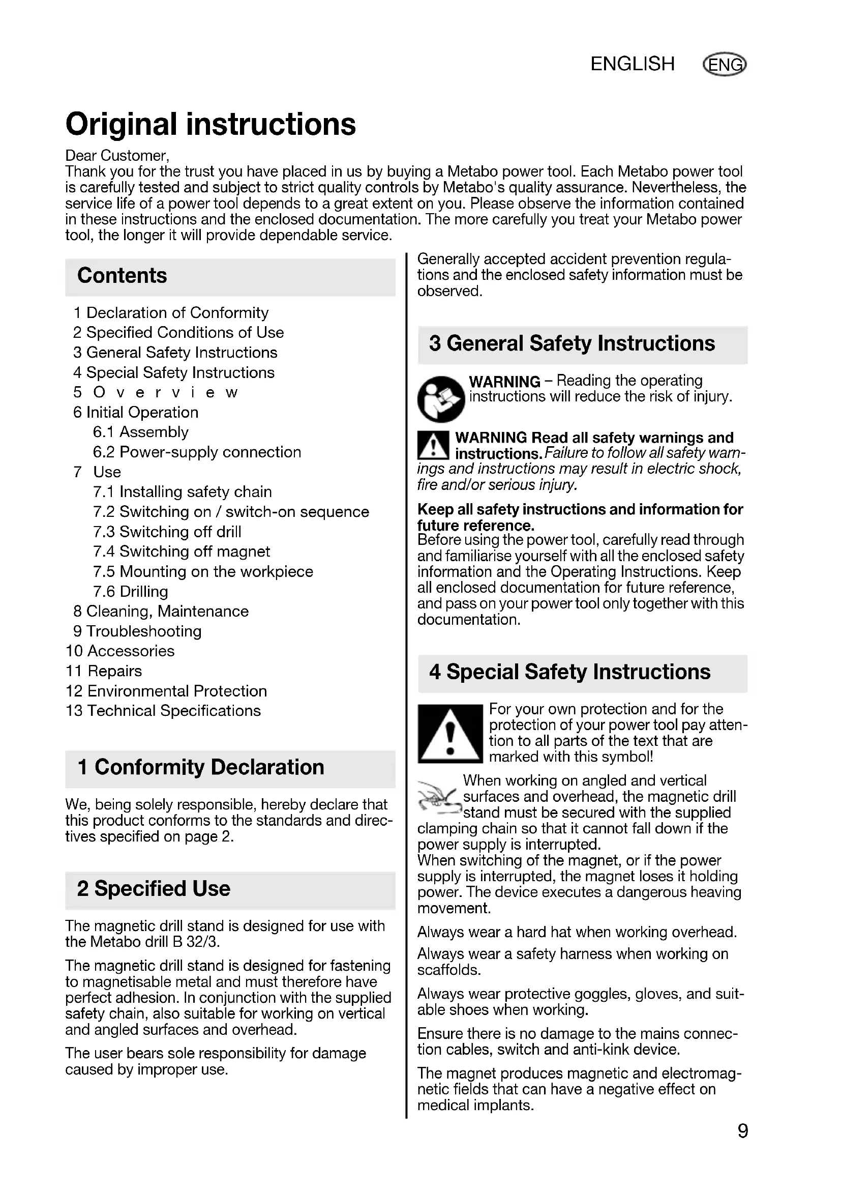
At the socket (4), only connect drills with the following current consumption:
at 110-120 V: maximum 12 ampere; at 220-240 V: maximum 9 ampere.
Before use, always check that the eccentric (13) is firmly clamped so that accidental displacement or rotation of the upper section is not possible.

Wear protective goggles.
Danger - electrical voltage.
Danger - magnetic field.

Persons with pacemakers prohibited.
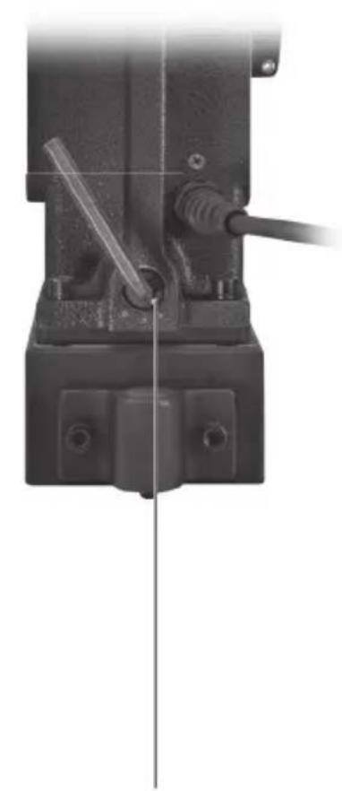
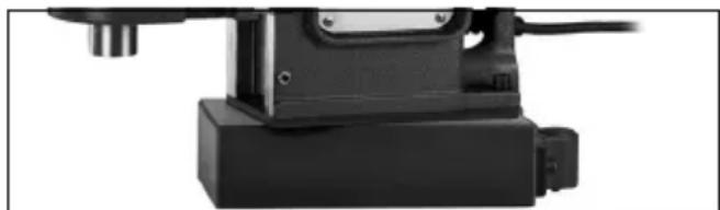
5 O v e r v i e w
See page 3.
1 Snap hook of safety chain
2 Safety chain
3 Holding points
4 Drill socket
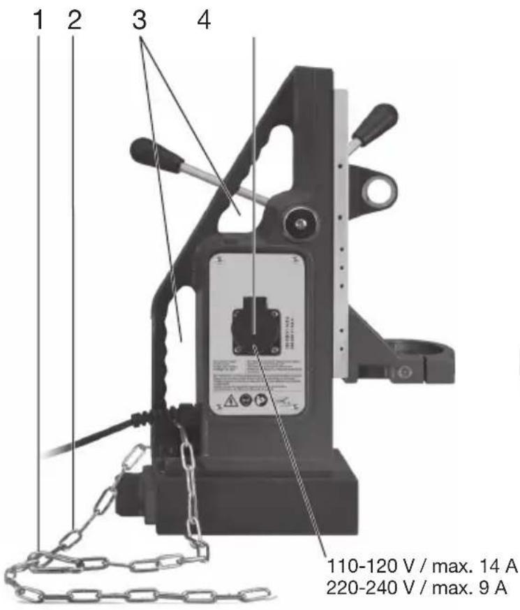
5 Slide plate
6 Threaded pins for adjusting backlash of the side plate
7 Lever
8 Spindle
9 Switch for switching on the drill
10 Switch for switching off the drill
11 Switch for switching magnet on and off
12 Magnet block / Magnet
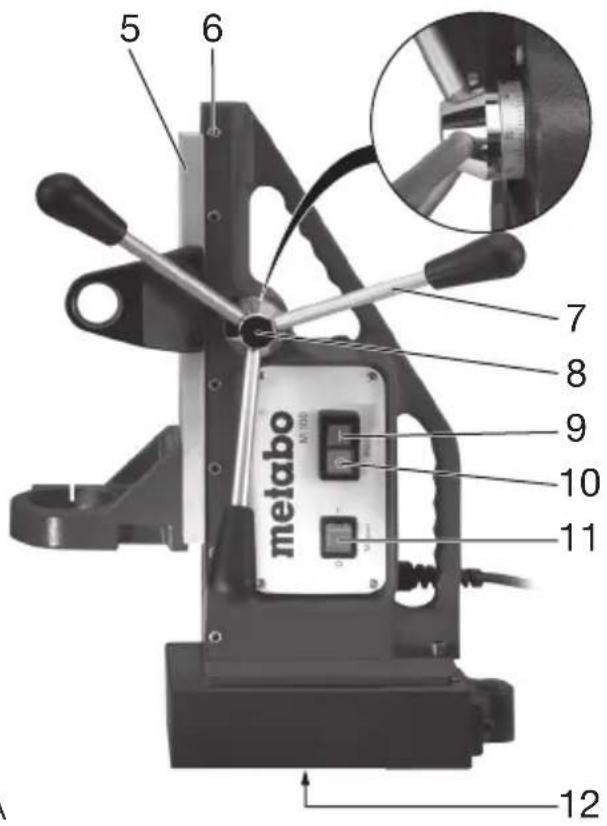
13 Eccentric
14 Screw for securing the drill
15 Holder for securing the drill
16 Clamping ring
17 Clamping ring screw
6 Commissioning
Before plugging in, check to see that the rated mains voltage and mains frequency, as specified on the rating label, match your power supply.
Check the unit for possible damage: Before using the unit, protective devices or slightly damaged components must be carefully checked for perfect and specified operation. Check that moving parts are in perfect working order and do not jam and check whether parts are damaged. All parts must be correctly installed and fulfil all conditions necessary to ensure perfect operation of the unit. Damaged protective devices and parts must be repaired or replaced according to specifications by an authorised specialist workshop.
6.1 Assembly
- Screw the 3 levers (7) firmly into the spindle (8).
-
Inserting drill B 32/3:
-
Unscrew additional handle from drill (observe the Operating Instructions of the drill).
- Align the drill so that the thread (into which the additional handle was screwed) faces the holder (15).
- Insert the drill collar into the clamping ring (16).
- Screw the drill with screw (14) onto holder (15).
- Tighten screw (17) of clamping ring.
- Press switch (10) and set switch (11) to "0" (so that the drill cannot start up).
- Insert mains plug of drill into socket (4) of magnetic drill stand.
- Set continuous operation at the drill. (Observe the Operating Instructions of the drill).
6.2 Mains connection
The magnetic drill stand is in protection class I and must therefore only be connected to sockets earthed according to specifications.
If an extension cord is needed, it must be a three-core lead with a protective (earth) contactor that is properly connected to both the plug and the coupler of the cord.
When working outdoors, only use the correspondingly marked extension cable approved for this purpose.
Regularly check extension cables and replace if damaged.
The extension cable must be suitable for the drill and magnetic drill stand power ratings (see Technical Specifications). If using a roll of cable, always roll up the cable completely.
7 Use
7.1 Installing safety chain

When working on angled and vertical surfaces and overhead, the magnetic drill must be secured with the supplied safety in (2) so that is cannot fall down if the power supply is interrupted.

Fit the safety chain (2) so that if the mains voltage fails the magnetic drill stand is fired away from the operator.

Caution! Check the safety chain (2) for damage. Before using the safety chain (2), check it carefully to ensure it is operating properly and as specified. If the safety chain (2) is damaged or the snap hook (1) is no longer in direct working order, replace the safety chain immediately.
- F i t safety chain (2) on one of the two holding points (3) of the magnetic drill stand.
- Then secure the safety chain to another suitable fastening point or to the material being processed. Hook the snap hook (1) of the safety chain into one of the chain links so that the chain is as taut as possible.
- Check that the snap hook (1) is completely closed.

The safety chain does not substitute the magnetic force of the magnetic drill stand, as simply used to secure against falling in the face of a voltage failure.
7.2 Switching on / switch-on sequence

For safety reasons, the drill can only be switched on after the magnet has been shed on. Please observe the switch-onence.
- First switch on the magnet: set switch (11) to "1". When the magnet is switched on, the indicator lamp built into the switch (11) lights up.
- Wait until this occurs before turning on the drill at the switch (9).
See also chapter 9.
Note: The full holding power of the magnet is available when the drill is switched on.
7.3 Switching off drill
Press switch (10). Wait until the drill has come to a complete standstill.
7.4 Switching off magnet

When the magnet is switched off, the magnet loses its holding power.
Set switch (11) to "0".
7.5 Mounting on the workpiece
To permit the magnetic drill stand to adhere properly to material that is to be drilled, the surface must be clean and smooth. Loose rust, dirt or grease must be removed before mounting the magnetic drill stand; any welding beads or surface irregularities must be smoothened. Thin coats of paint will not impair adhesion. Clean the magnet block as well (12) if necessary.
After switching the magnet on, hold the handle of the magnetic drill stand and shake it firmly to ensure that the unit is adhering properly. If it is not, then check the condition of the surface of the material and that of the bottom of the magnet block. Clean as necessary and try again.
Use on thin steel
The unit adheres best to low-carbon steel that is at least 12mm thick.
For drilling a hole into thin steel, a steel plate measuring at least 100 × 200 × 12 ~mm can be secured under the material at the place where the magnetic stand is to be positioned.
Non-ferrous metals
To drill a hole in non-ferrous metal, the steel plate should be secured on the surface of the material and the magnetic drill stand then placed on the steel plate.
Round or cambered surfaces
If you need to drill into a round or cambered surface, then the magnet block (12) should be positioned with its longitudinal axis parallel to the axis of the camber.
The open space between the magnet block and the camber should be packed with steel wedges or rods on both sides along the entire length of the magnet block so that after switching on the magnet as many as possible magnetic lines of force are conducted from the magnet pole through the wedges (or rods) and the material to the magnet block housing.
Ensure that the steel wedges (rods) on both sides of the magnet block are distributed such that the axis of the drill bit is aligned directly to the centre of curvature; otherwise it could be diverted to one side.
By shaking the handle of the magnetic drill stand, make sure that the stand adheres properly to the material.
7.6 Drilling
-
Observe the Operating Instructions of the drill.
-
Centre the position at which the hole is to be drilled.
- Align the magnetic drill stand so that the drill bit is near the centre marking.
- Switch on the magnet of the magnetic drill stand (switch (11)).
- After releasing the eccentric (13), the upper section of the magnetic drill stand can be rotated and laterally shifted so that the drill bit is exactly above the centre marking. Important! Firmly clamp the eccentric (13) again.


Before use, always check that the eccentric (13) is firmly clamped so that accidental placement or rotation of the upper section is not possible.
- Then switch on the drill (switch (9)).
- Start the drilling operation with minimum feeding force.
- When the drill bit has started to drill, slightly higher feeding force can be applied. Excessive feeding force leads to premature wear of the drill bit. Ensure that the chip flow is regular
- The graduated collar at the spindle (8) is used to determine the drilling depth.

If (after use) the magnetic drill stand is placed on a material with low heat-dissipation characteristics for a long period (e.g. plastic), the net must not be switched on because this will lead to overheating of the magnetic coils.
8 Cleaning, Maintenance
Perform regular maintenance work, cleaning and lubrication.
Disconnect the mains plug before starting any setting, maintenance or repair work.
For lubricating the rack and pinion that moves the slide plate (5) up and down, a few drops of oil should be applied occasionally to the rack.
Coat the sliding surfaces of the slide plate (5) with multi-purpose grease.
Backlash of the slide plate
The backlash of the side plate is set ex works.
The side plate (5) must be adjusted so that while the slide plate (with motor installed) can still be moved freely up and down, it will remain in any position without the weight of the drill pulling it down.
The backlash of the side plate (5) can be adjusted as required using the seven threaded pins (6).
Release lock nuts, tighten threaded pins and retighten lock nuts.
9 Troubleshooting
Electronic restart protection (for preventing accidental restarting)
If, with the drill switched on,
a) the magnet is switched off or
b) the power supply is interrupted, the drill comes to a standstill.
If the magnet is then reactivated or the power supply restored, for safety reasons the drill does not restart automatically (electronic restart protection). Turn the drill back on at the switch (9).
See also chapter 7.2.
10 Accessories
Use only genuine Metabo accessories.
If you need any accessories, check with your dealer.
For dealers to select the correct accessory, they need to know the exact model designation of your power tool.
For a complete range of accessories, see www.metabo.com or the main catalogue.
11 Repairs
Repairs to electrical tools must be carried out by qualified electricians ONLY!
The connection cable must only be replaced by Metabo or an authorised customer service workshop.
Contact your local Metabo representative if you have Metabo power tools requiring repairs. For addresses see www.metabo.com.
You can download a list of spare parts from www.metabo.com.
12 Environmental Protection
Metabo's packaging can be 100% recycled.
Scrap power tools and accessories contain large amounts of valuable resources and plastics that can be recycled.
These instructions are printed on chlorine-free bleached paper.

Only for EU countries: Never dispose of power tools in your household waste! In accordance with European Guideline 2002/
96/EC on used electronic and electric equipment and its implementation in national legal systems, used power tools must be collected separately and handed in for environmentally compatible recycling.
13 Technical Specifications
Explanatory notes on the specifications on page 2. Changes due to technological progress reserved.
H_ = Maximum stroke
P1 = Nominal power input
F_ = Maximum adhesive force
A = Dimensions of magnet block
m = Weight without mains cable
The technical specifications quoted are subject to tolerances (in compliance with the relevant valid standards).
Notice originale
Cher client,
Varning for livsfarlig elspanning!
Varning for magnetfalt!
Forbjudet for dig som har pacemaker.
5 Överversikt
Se sid. 3.
Fmax = max. faskraft
A=Mattpamagnetfoten
m = Viktutan sladd
Reservedelslicer kan downloads pa www.metabo.com.
12 Miljøbeskyttelse
TOLOBOM MaHHTbI WtTaTbN CLeDyET
3aKpeNTb C NOMOUsb BxOJaueB KOMNJIeKT NOCTaBKn CTJXHOI CEIN, YTO6bl NCKJIIOHTb BO3MOXHOCTb eO NaDeEHnB CJIyuae C60B B NOdaue 3/NTaHnA.
PnBbIKIOueHm 3/MaHHTa NIN B CNYae C60B IOnaue 3/NTaHn MaHNT TepeT CBOU yDepKbBAIOUcNny. INCTpyMeHT BbINOJHReT ONaCHOE MaTHNKOBOE DBNKHeHne.
Pn BbINOnHeHn pa60T HaI rOIOBcJIeDyET HaDeBaTb 3aUHTHyIO KACKy.
Pn pa6oTe Ha Iecax noIb3yItecB CTpaxOBOHbIM pemHEM.
Ipepe pa60ToBcerdaHaDeBaTe 3aunTHbIe OoKN, 3aunTHbIe nepaATKn I NOxOJaUyIO 0byBb.
Y6eHnTeCb B OTCyTCTBnN IOBpeXJeHn CeTeBOKa6eI, BbIKJIOuHaTeJI N OTCyTCTBnN Cn6OB.
Bo3HnkaOuIe MaHHTbIe n 3/MaHHTbIe NOJI MOryT OTPnCaTeJIbHO BO3DeIcTBoBaTb Ha pa6O TY MednUHCKNX MMJIaHTaHTOB.
IobepxHOCTb IJyYCTaHOBKn 3/MaHHTa DOJXHa 6bITb YNCTOINPOBHOJ.
YdepxnBaOuaCnnaMaHnTa3aBnCTOT TOJIuHbI MaTePnAnaN erO CBOICTB.
PnHaJIuHcNcIeKpackn,unHka nOKaIIINbI ydepXNBauOuaCnla 3/MarHNTa CHNXaETCA.
He nCNoJIb3yIte MaHnTHbI MtTaTbN IOd DOxKdE, a TaKxE BO BNaXHbIX NIN B3pbIOONaCHbIX NOMeUeHNrX.
IpepeBbIOpJIHeHnEM pa6oT no peryJnIPOBKe IIN TeXO6CnyKuBAHNIO CBepJIbHOY yCTaHOBKn BbIHMaIte eE BUNKy N3 PO3eTKM MaHHTHO TtATNaBa.
BHHMaHHe!PnN3BLeueEHmCeTeBOB BUNKuWtTaTbVa ydepXNBaIOUaCnJa MaHHTaNCe3aeT.
Co6JIIOdaIte pyKOBOcTBO NO 3KcJIpyaTauN CBePnJIbHOJ yCTaHOBKn.
K po3eTke (4)doJXHbI NOkJIIOuTaBcra TOLbKO CBepNJbHbIE yCTaHOBKn CO CJeDyIOUIM NOTpe6JIeHNEM TOKa:
PnHapJxKeHN 110-120 B:MaKc.12A;
Pn HapJxKeHN 220-240 B:MaKc.9 A.
Ipepe KaKdbIM NcNoJIb3OBAHHeM npOBepaTe HaJExHOCTb 3aXIma 3KcUeHTpNka (13) BO n36exHaHne ClyuahHoro CMeueHnI INBbaSeHnB BepxHeY qactn.

HaedeBaIte 3aunTHbIe OUKN.

IpeDynpexKdHne o6 onachOM 3JeKtpnueckom HapnxKeHH!

PpeynpeKdHne 06 3/MaHnTHOM noJe.

3anpetdIJI Nc 3/kapDIOCTMMyJATOpOM.
50630p
CM.c.3.
1 KpIOK-Kapa6Hn CTpaxOBOuHOHcENI
2 CtpaxoBOuHaIeIb
3TocknKpenneHn
4 Po3eTka dIa CBepInbHOyCTaHOBKn
5 KapeTka
6 LnnIbKn dIepeRynipOBKn 3a3opa KapeTkn
7 Pbl qar
8UnnHdJIb
9 BbIKJIOUaTeIb IJI BKJIIOUeHINCBepnIbHOYyCTaHOBKN
10 BbIKIOUaTeJIb DnB BbIKIOUeHnA CBePINbHOy yCTaHOBKn
11 BbIKIOUaTeJIb IJRA BKIOUeHnI N BBIKIOUeHnI 3/MaHHTa
12 MarHHTHa nOdoWbA/marHnT
13 ΘκιεHTρικ
14 BnHT dIa KpeIeHna CBeprIbHOyCTaHOBKn
15 DepxkaTeIb Ia KpeIJIeHn CBeprIINbHOYcTaHOBKn
16 3axkIMHoe KOJIbIcO
17 BnHT 3axmHoro KoJbua
6 BbO B 3KcPnyatauHIO

IpeB BBOOM B 3KcNJIyatauIO npOBepbTe COOTBETCTBNE HAnpJKeHnI uACTOTbICETn, aHHbIX Ha 3aBOIDCKoTbINuKHe, npaMeTpam 3JeKTPoPNTaHnI.

PpOBepbTe HNCTpyMeHT Ha OTCyTCTBne BO3MOXHbIX NOBpeKdEHN: nepeD
JaIbHeIMNCIOJIb3OBAHnEMNHCTpyMeHTa CNeIyET TuaTeJIbHO IPOBepNTb IpaBnJIbHOe N 6e3yIpueHoe yHKUHOHnPOBaHne 3aUNTHbIX npICNOCO6JeHn nn DeTaNen, IMeIOUX He3NaHTeJIbHbIE NOBpeKDeHn. IPOBepTe CBO6Ody XoJa IOdBnXhBX DeTaNen. Y6eJntEcsB OTCYCTBn INx 3aKJIINHBaHn INI IOBpeKDeHn. BCE DeTaNcNEyET IpaBnJIbHO CMOTnpOBaTB n BblINOHNb BCE ycNOBnI NO ObecneHuN IX
6e3ynpueHno pa6oTbI. NObpeXdEHHbIe 3aunTHbIe npncnOcObeHn I DeTaJI NOpJExKAT peMOHTy nJI 3aMeHe B CneuaJIuN3IpOBaHHOM cepBnCHOM ueHTpe.
6.1 C6opka
- BvepHnte 3 pbyara (7) B wnnHdJIb (8).
- YCTaHOBnTe CBepnIbHyIO yCTaHOBky B 32/3:
-OTBepHnTe DOONHnTeIbHyIO pyKoRTKy CBepNlNbHOY yCTaHOBKn (CM. pKOBOIDCTBO NO 3KcNJIyatauIN CBepNlNbHOY yCTaHOBKn).
- BbipOBHnTe CBepnNbHyO yCTaHOBky TaKIM O6pa3OM, YTO6bl pe3b6a (pe3b60BOe OTBepCTne DnI DOONHHTenbHOn pyKoRTKn) 6blna HAnpaBHeHa DepxKaTeNb (15).
- BCTaBbTe 3axmHyU weKy CBepnIbHOn yCTaHOBKn B 3axmHoe KOJIbO (16).
- PnBepHnte CBePnJIbHyIO yCTaHOBky BnHTOM (14) K DePkaTeJIO (15).
- 3aTAHNTe BnHT (17) 3axmHOrO KoIbua.
-HaxMMTe BbIKNIOUaTeIb (10) n yCTaHOBnTE BbIKNIOUaTeIb (11) Ha «O» (BO n36eKaHne 3anycka CBePnINbHOJ yCTaHOBKn).
- BCTaBbTe ceteByIO BnIKy CBepnIbHOn yCTaHOBKn Bpo3eTky (4) uTaTnBa.
- YCTaHOBInTe Ha CBepINbHOJ yCTaHOBKepeKIM HeNpePBIBHOJ paBOtbl. (Co6JIIOJaIte pyKOBoDcTBO no 3KcIIpyTaUIM CBepINbHOJ yCTaHOBKn).
6.2ПодключенkeCetTu/NTaHnA
UtaTb C MaHHTOM COOTBETCTBYET KNaCcy 3aUntbl N NO3Tomy DOJXeH NOKJIIOuATbcA TOIbKO K COOTBETCTBYOUIM O6pa3OM 3a3eMJIeHHbIM p03eTKam.
Pn nCNoJb3OBAHn ydInHnteHbHO Ka6eN Bbl6paIte 3-xxnbHbIK Ka6eIb (ero 3aunTHbIM npBOoD dONKeH nMeTb NCpabHoe COeINHeHne C 3aunTHbIM KOHTaKTOM CoeINHNTbHO p03ETKN C BNKo).
PpnaPabotax BHe NOMeHnN nCNoB3ynte TOnbKO dOnyuEHHbIe K 3KcNlyaTaunu yDInHnTeNbHbIe Ka6JInc C COOTBeTCTByIOUeM MapKnropOBkO.
PeryIaRHO npOBepaTe ydINHInTeJbHbIe Ka6JIu I npHaJIuHn NOBpeKDeHn 3aMeHAnTe INX.
YdINHHTeBHeI KabeN DoJXHbI COOTBETCTBOBaT NOTpe6JIReMOI MOUHOCTN CBepnIbHOYcTaHOBKNu WtTaTnBa (cp. TexHueckne XapaKTePncTnKn).Ppn IcNoB3OBAHH KabeJI B 6yXTe O6a3aTeJIbHO IONHOCTbIO CMaTbIBaNTe Ka6eJIb.
7 3ксплуataця
7.1 UctaHOBka CtpaxOBOUHOIeH
Для pa60Ты HaHaKJIIOHbIXи ВерTKaJIbHbIX NOBepxHOCTX ИИн Нд ГОВОй STaTNB CNeIyET 3akpeNTb C NOMOьIO BXODIeB B KOMNJIeKT NOCTaBKN CTpaxOBOHON ueN (2), YTO6bl NCKIIOUHTb BO3MOJXHOCTb eE NaDEHn Iprn BO3HnKHOBEHm C6OB B NODaYe 3/NTaHn.
YCTaHOBnTE CTPaxOBOHyU cIb (2) TaKIM O6pa3OM, YTO6bl WtTaTnB pIe OTCyTCTBnN 3/ NITaHnHe CMeuJcR B CTOpOHy OT ONEpaTOPa.
BHNMaHHe!PpOBepbTeCTpaxOBOUHyIO ueb (2)HaOTcyTCTBne NOBpeJdeHn.Ipeed KaKdbIM NcNoJIb3OBAHNEM TuaTeJIbHO npOBepaIte CTPaxOBOUHyIO ueb (2).B clyuae IOBpeXdEHHa CEIN (2)NJN HApUWeHHa FyHKuIN KpIOKa-Kapa6bHa (1) CTPaxOBOUHyIO ueb CNe dyET HeMeJeHHo 3aMeHHTb.
- 3akpennte ctpaxoBOUHy zuB (2) 3a OndHy n3 Touek KpenneHn (3) wTaTnBa.
-3aTeM 3aKpeNITe CTPaxOBOCHUo CEbB DpyroI NOxOJaIeT OUKe KpeJIeHnI NnHa 06pa6aTbIbAemOM MaTePnaIe. 3aKpeNITe KpIK-Kapa6bHa (1) CTPaxOBOCHo CEIIIN B ODHOM I3 3BeHbE B CEII TAKIM O6pa3OM, YTO6blcIb 6blIa NIO BO3MOXHOCTN Tyro HATryTa.
-Проверът,зakрьтлкрюк-Kapабн(1).
CTpaxoBOUHnAeHbHe3aMeHHet cyHKUIO MarHNTa WtTaTINBa; OHa CnyXHT TOIbKO DnA 3aUNTbI OT NaDeHNB CNYuae C60B B NOdaYe 3/NTaHnA.
7.2 BkIouHeH/npaOK BkIOueHnA
IIO COO6paXeHnM 6e3OnaChocTn BKIOUaTb CBePJIINbHyIO YCTaHOBky MOxHO TOIbKO NOCIE BKIOUeHnMaHnTa. Bcerda CO6IIOdaIte 3TOT NoprIDOK BKIOUeHnR.
-
Chauana BkIIOUHTe 3/MaHNT: yCTaHOBNTe BbIKIOUaTeNb (11) Ha «1». Nocne BkIIOUeHnMaHNTa 3aropaeTc CnHaJIbHaJ lamna, BCTpoEHHaB B BbIKIOUaTeNb (11).
-
TóJBko NOCne 3TOrO MOxHOb BKJIIOuHaTb CBePJIINbHyIO yCTaHOBky C NOMIoUbIO BBIKIIOuHaTeJIa (9).
Takke m. 9.
IpimMeaHHe:MaHHT OblaJaET NOHOn ydepxnBaIOSei CnIOI pR NkIIOueHHoCBePnJIbHOY UCTAHOBKe.
7.3 BbIKIIOUeHne CBepINbHOyCTaHOBKn
HaxMnte BbIKIOuateJIb (10).NoOxKnTe, noka yCTaHOBka He OCTaHOBnTCr NOJHOCTbIO.
7.4 BbIKIOUeHne 3/MaHRHTa

Pn BbIKIOueHm MaHHTa ydepKNaIOua Cnla MaHHTa Ncye3aeT.
YctahOBNTe BbIKNoUaTeIb (11) Ha «0».
7.5 YcTaHOBKa Ha 3arOToBky
UtaTb C MaHNTOM ydeXnBaetcHaJaEHO Ha MaTePnaJe, B KOTOpOM BbIOnHReTcCBepNeHHe, TObKO B TOM Cnyaee, ecn erO NOBepxHOCTb YnCTa N POBHa. Pepey cTaHOBKO uTaTbA CLeDyET ydaJIHTb CLeDbI PkAbuHbI, rpa3b N CMa3Ky, BblPOBHATb BO3MOXhBl rpaT, O6pa3yUoJmCn Prn CBapKe, IInn HbIe HEPOBHocTN. ToKni CNoi KpackN Ha UdepXnBaHne He BnIeT. Ppi Heo6xOIMOCtN CLeDyET TaKke OUnCTntb MaHHTHyIO NoDOUBY (12).
Iocne BkIoUeHn 3/MaHnTaNoepraTe C ycnInem 3a pyKoAry MaHnTHOJ CToKn, YTO6bI yBeiHTbcB TOM, YTO uTAtNb HaJeXHO yDepxNBaeTcH Na MaTePnaJIe. Ecnn 3To He TaK, nPOBepbTe NOBepxHOCTb MaTePnaJIa N HIXHIO CTOpOHy MaHnTHOJ NDoOWBbl; PpN Heo6xoDMOCtN OuNCTNTe N BkIoUChTE 3/MaHnT NOBTOpHO.
CTaJIb He6oJbwoi ToIuHbI
OnTmMaIbHoe ydepxKBaHne Ha
Hn3KoyrIepoNCTOcTaN ObecneuBaetc npn eToJIuHe He MeHee 12 MM.
Дя CBepнЯВ Cталс MeHbWeJ TOJIINHO MOxHo yCTaHOBnTb NOД MaTePnaJ (В TOM MecTe, Ге уCTaHaBnBaEcR MaHHTHaN NOOwBa) CTalbHyIO nIacTHNu (MnH. pa3Mepbl 100 x 200 x 12 MM).
UBeTHbIeMeTaJIbI
Дя CBepнь B UBeTHbIX MeTaJIax Ha MaTePnAne 3aKpeNJIeTc RAJIbHЯ ПlaCTnHa, Ha KOTopyU yCTaHaBJIbBaETc WtATNB.
Kpyrln nn rHytbmatepnaI
Длгсверленя крглори ИлгHyTORO MaTePnaja MaHHTHa NOdoWbA (12) ycTaHaBnBaeTcHa MaTePnaj TAKIM O6pa3OM,чTObI eE npOdoJbHaN OCb npOXoJna napaJIeJIbHO npOdoJbHO NcMaTePnaja.
3a3op MeKdy NOOWBOn I MaTePnAOn MHa OBeX CTOpOHax N0 BceN DInHe NODoWBbl CNeDyET 3aONHnTb CtaJbHbIMN KINHBaMn INNCTePKHM TaKIM Obpa3OM, YTO6bl NocIe BKJIIOUChENr 3/ MaHTa Chepe3 KInHbI (INN CTEpKHN) IN Chepe3 MaTePnAJI K KopnCy MaHTHOI NOoWBbl OT MaHTHORO NOIIOCA npOXoDnla NO BO3MOxHOCTN 6OJIb7aYacTb CINOBbIX INHm MaHTHOrO NOJIA.
CTaJIbHbIe KInHbIa (CTepxHn) CneDyET
pacnpedeJIbTb IO OBeIM CTOpOHam NDoOWBbl
TaKIM 6bpa3OM, YTo6bl Ocb CBepNa 6bla
HaPpABJIeHa IprAMo Ha CEHTp rHyTORo MaTePnaJa,
Tak KaK B IpOTNBHom Cnyae BO3MOKeH yBOd CBepNa B CTOpOHy.
IOneprab 3a pykoTky uTaTnBa y6eNITecb B TOM, yTO OH HaJExKHO 3akpePnE H aMaTepnae.
7.6 CbepeHne
-CobIIOdaIte pyKOBODCTBO NO 3KcNpyaTcuIN CBepJIbHOY yCTaHOBKN.
-C NOMOJIbIO KepHa BblIOJHnTe pa3MeTKy 6byduero OTBepCTnIa.
-BbipOBHnTe WtTaNb TaKIM O6pa3OM, YTO6bI BepuHa CBePJa HaxOdiJacb B6JIn3N OTMeTKn.
-BKJIIOUHTe 3/MaHHT WTaTnBa (BbIKJIIOuHaTeJb (11)).
-ПослеслабеленяЗкцentриka(13)ВерхиюЧаctь Магнштого StTaTиBa MoxHо NOBepHytв ИСдВиHTb B CTopoHу TaKIM OБразOM,чTOбI Вершиha CBepla HaxOДиJaCb TOHо HaDOTMETKO. BHIMaHne! ChOba 3aTЯнITEЗКсцentриK(13).

IpeepKaKdbIMNCIOJb3OBAHnEm npOBepaTe HaDeXHOCTb 3aXnMa
3KcEHTpika (13) BO n36ekajnne cnyaHoro CMeueHnna nnBpaueHnna BepxHe Yaactn.
- 3aTeM BKJIIOUHTe CBepINJbHyO yCTaHOBky (BbIKJIIOUHTeJIb (9)).
- NaHnTe CBePJIb c He6OJIbIIM yCNIeM nOdaun.
- KaTToIbKO CBepNo BOiDET B MaTepeNaI, ycNIne IoJaH MoXHo CJIeKa YBeJIuHnTb. CInuKOM BoJbOoe ycNIne IoJaH nPnBOJNT K npExdEBPeMeHHOMy N3HOcy CBepNa. PeryIpaH O ydaIraIte oNnKn.
-Дя onpeDeHnI rIy6uHbI OTBepCTn CnyKNT KOJIbO CO uKaIOn Ha uINHeIe (8).

ПинхжденишТиВа(пocгИСПОЛБ3OBAHN)ВTeчEHNE
PPOJONKHTeJIbHO BpeMeHn Ha MaTePnaJe C HeOCTaTOUHbIM TeNIOOTBODOM (HaIpIMep, PNaCTMaCCa) BKIOUcTa MArHNTbI 3aIpeuaeTcR, TAK KAc 3TO MOKeT pINBecTu K NpeperpeBy KaTyweK 3/MaHNTa.
8 OuNTka, TexHnueckoe 06cIyXnBaHne
CJeNyEt pEryIaRpHo BbINOJIHaTb TexHnueeCKoe 06cIyXnBaHHe, OuNCTKy I CMa3Ky WtTaTnBa.
Ipepe npoBeHnem IIO6bIX pa60T no
peynilpoBKe, pemOHTy nIN TexHnueCKOMy
OcnyKuBaHnIO CNeDyeT BbIHytb CeTeByIO BuNKy
n3 po3eTKn!
Дя Смдзубчatoштанишостepн Дяпдьеми ONyckaня Kapetkn (5) Hahecnte Heckoьko Kanelb Macna Ha Stahry.
CmaKbTe NOBepxHocTn cKoJIbXeHnA KapeTKn (5) yHnBepCaJIbHOJ CMA3KOJ.
3a3op Kapetkn
3a3op Kapetkn yctaHaBnBaETcHa 3aBOe.
Kapetky (5) cne dyet OTperynpoBaTb TaKIM
6bpa30M, yTObI OHa (npi ycTaHOBJIeHHO
CBepnIbHOY UCTaHOBKe) IeTKO nepemeuaacb
BBepx IN BHN3, OCTaHAbINBaJACb B JIO60
IO3nCmN H He ONyckaJAcB IOd CInNo TjXeCTN
yCTaHOBKn.
Pn Heo6xOAnMoCTN MoXHO OTperyIInpoBaTb 3a3Op Kapetkn (5) c NOMOuBIO cEmu IINIEK (6). Ocna6bTe KOHTprAKn, 3aTaNHTe IINIBKN I CHOBA 3aTaNHTe KOHTprAKn.
9 YcTpaHeHne HenCnpaBHOCTeI
3aunTa OT NOBTOPHORO Nycka (BO n36exKaHne cnyaHoro BKIOUeHnA)
Ecn npn BkIIOeHHo CTaHka
a) 3/MaHHT BbIKJIOUaETCNJIIN
6) IMeET MeCTO C60B B NOdaYe 3/INTaHnCBepnIbHaYcTaHOBKa OCTaHaBnBaETCa.
При NOВTOPHOM BKЛIOUeyHIM 3/MaHHTa NII BO306HOBJIeHIM NOdaH 3/NTaHIN YCTaHOBka (NOCOo6paxKeHnM 6e3OpaCHOCTn) ABTOMaTnueCKN He BKNIOuayTeC (3aUNTa OT NOBTOPO Nycka). BKJIIOUYte CBepINbHyO yCTaHOBky C NOMOUsBO BBKIOUaTeTЯ (9).
Takke cm. 7.2.
10Пинадлжноctn
IcnoJb3yIe ToJIbKO opuHaJIbHbIe npHaJdLeXHoCTn Metabo.
EcnBam Tpe6yOTc npHaJnHexHocTn,
ObaaataTeCb K Baawemy dInepy.
A = pa3Mepbl MaHHTHO NOOWBbl
m = Macca 6e3 ceTeBOrO Ka6eJr
Ha yka3aHHbIe TexHnueckne xapaKTepeNTIKn pacnpocTpaHIOCTdONyCKN, npEynCMOTpeHHbIE DeiCTByUOIMN CTaNapTaMn.
metabo®
Metabowerke GmbH, 72622 Nürtingen, Germany
www.metabo.com