USER MANUAL PW 360 HUSQVARNA


natural_image
Two identical mechanical devices with wheels and handles, shown in side-by-side assembly, no text or symbols present.
natural_image
Mechanical assembly diagram showing a connector inserted into a housing with a directional arrow indicating motion (no text or symbols present)

natural_image
Illustration of a handheld device with a magnified inset showing a close-up of its internal components (no text or symbols present)
natural_image
Mechanical device with rotating dial and mechanical components, no visible text or symbols
flowchart
graph TD
    A["Tool Insert"] --> B["Rotation"]
    B --> C["Assembly"]
    C --> D["Ordering"]
    D --> E["Assembly"]
    style A fill:#f9f,stroke:#333
    style B fill:#ccf,stroke:#333
    style C fill:#cfc,stroke:#333
    style D fill:#fcc,stroke:#333
    style E fill:#ffc,stroke:#333
28
natural_image
Diagram of a firearm being inserted into a cylindrical device, showing mechanical components and motion arrows (no text or symbols)
30
natural_image
Technical illustration of a handheld device with a close-up view showing internal components (no text or symbols)
31
GENTLE NOZZLE ROUGH NOZZLE SHORT NOZZLE


32
natural_image
Diagram showing two mechanical components with arrows indicating direction (no text or symbols)
natural_image
Diagram of a connector with arrows indicating direction (no text or symbols)
34
35
natural_image
Diagram showing a hand tool and its internal components, with arrows indicating motion or assembly (no text or symbols present)

natural_image
Diagram showing a device being inserted into a cable, with arrows indicating the process (no text or symbols present)
natural_image
Illustration of a firearm being inserted into a cylindrical device, showing step-by-step assembly (no text or symbols)
natural_image
Diagram of a faucet with a tap and arrow indicating upward movement (no text or symbols)
natural_image
Illustration of a double faucet with two arms and one valve, showing fluid flow direction (no text or symbols)
natural_image
Technical diagram of a mechanical component with two threaded fasteners and directional arrows indicating assembly (no text or labels)
natural_image
Mechanical component diagram showing a valve assembly with directional arrows indicating movement (no text or symbols)
natural_image
Line drawing of a fuel nozzle and plug assembly (no text or symbols)
natural_image
Technical illustration of a handheld device with a lever and plug, showing a mechanical assembly and a separate component (no text or symbols)
natural_image
Illustration of a faucet with a tap and arrow indicating water displacement (no text or symbols)
natural_image
Mechanical assembly diagram showing a tool inserted into a car's head panel with a screw and valve (no text or symbols)
natural_image
Line drawing of a plug with a cable and two padlock icons (no text or symbols)
natural_image
Line drawing of a fuel pump with lock and plug, showing a valve mechanism and lock icons (no text or symbols)
natural_image
Diagram of a circular device with internal bands and directional arrows indicating motion (no text or symbols)
natural_image
Mechanical device with directional arrows indicating motion or rotation (no text or symbols)
natural_image
Technical diagram of a vehicle's engine and water spray bottle assembly (no text or symbols)
natural_image
Illustration of a spray gun with three sequential action arrows showing the motion of the gun's tip and handle (no text or symbols present)
natural_image
Diagram of a mechanical device with a rotating arrow indicating rotation (no text or symbols present)
natural_image
Three technical diagrams showing a mechanical component being inserted, with one being reduced by a downward arrow (no text or symbols present)
natural_image
Two technical diagrams of a vacuum cleaner with arrows indicating assembly or operation (no text or symbols present)
natural_image
Mechanical assembly diagram showing a tool inserted into a component with a magnified inset detail (no text or symbols)

natural_image
Illustration of a faucet with a tap drop and a mechanical component (no text or symbols)
natural_image
Technical diagram of a mechanical component with arrows indicating motion or force direction (no text or symbols)
natural_image
Illustration of a hand tool applying force to a mechanical component, showing a needle inserted into a cylindrical part (no text or symbols present)
natural_image
Technical illustration of a mechanical device with a cylindrical component and directional arrow indicating motion (no text or symbols)
natural_image
Technical illustration of a mechanical component with a cylindrical part and threaded end, showing an arrow indicating direction (no text or symbols)
natural_image
Technical illustration of a mechanical assembly with threaded shaft and housing (no text or symbols)
natural_image
Technical illustration of a mechanical assembly with threaded components and a separate clamped part (no text or symbols)
natural_image
Mechanical assembly diagram showing a cylindrical component being inserted into a spring-loaded housing with directional arrows indicating motion (no text or symbols present)
natural_image
Illustration of a hand holding a textured cylindrical object and a faucet spraying water (no text or symbols)
natural_image
Mechanical assembly diagram showing gear and wheel components with directional arrows (no text or labels)
natural_image
Technical illustration of a mechanical device with gear and belt assembly (no text or symbols)
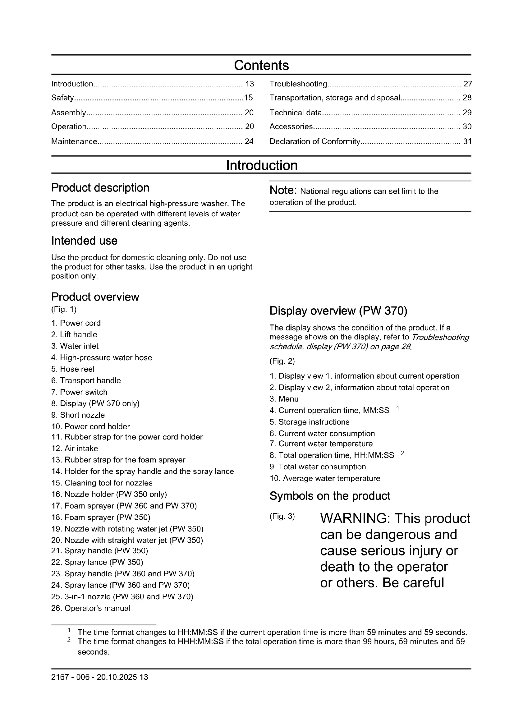
Contents
Introduction.... 13
Safety....15
Assembly.... 20
Operation.... 20
Maintenance.... 24
Troubleshooting.... 27
Transportation, storage and disposal.... 28
Technical data.... 29
Accessories.... 30
Declaration of Conformity.... 31
Introduction
Product description
The product is an electrical high-pressure washer. The product can be operated with different levels of water pressure and different cleaning agents.
Intended use
Use the product for domestic cleaning only. Do not use the product for other tasks. Use the product in an upright position only.
Product overview
(Fig. 1)
-
Power cord
-
Lift handle
-
Water inlet
-
High-pressure water hose
-
Hose reel
-
Transport handle
-
Power switch
-
Display (PW 370 only)
-
Short nozzle
-
Power cord holder
-
Rubber strap for the power cord holder
-
Air intake
-
Rubber strap for the foam sprayer
-
Holder for the spray handle and the spray lance
-
Cleaning tool for nozzles
-
Nozzle holder (PW 350 only)
-
Foam sprayer (PW 360 and PW 370)
-
Foam sprayer (PW 350)
-
Nozzle with rotating water jet (PW 350)
-
Nozzle with straight water jet (PW 350)
-
Spray handle (PW 350)
-
Spray lance (PW 350)
-
Spray handle (PW 360 and PW 370)
-
Spray lance (PW 360 and PW 370)
-
3-in-1 nozzle (PW 360 and PW 370)
-
Operator's manual
Note: National regulations can set limit to the operation of the product.
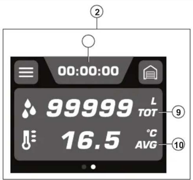
Display overview (PW 370)
The display shows the condition of the product. If a message shows on the display, refer to Troubleshooting schedule, display (PW 370) on page 28.
(Fig. 2)
-
Display view 1, information about current operation
-
Display view 2, information about total operation
-
Menu
-
Current operation time, MM:SS 1
-
Storage instructions
-
Current water consumption
-
Current water temperature
-
Total operation time, HH:MM:SS 2
-
Total water consumption
-
Average water temperature
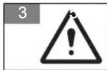
Symbols on the product
(Fig. 3)
WARNING: This product can be dangerous and cause serious injury or death to the operator or others. Be careful
and use the product correctly.
(Fig. 4)
Read the operator's manual carefully and make sure that you understand the instructions before you use this product.
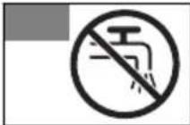
(Fig. 5)
The product is not suitable for connection to the potable water mains.
(Fig. 6)
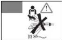
High-pressure water jets can be dangerous if subject to misuse. The jet must not be directed at persons, electrical equipment or the product.
(Fig. 7)
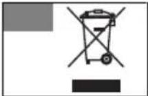
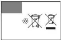
Environmental mark.
The product or
package of the product
is not domestic
waste. Recycle it
at an approved
disposal location for
electrical and electronic
equipment.
(Fig. 8)
Class II tool.
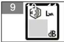
(Fig. 9)
Noise emission to the environment label as per
EU and UK directives and regulations, and New South Wales legislation "Protection of the Environment Operations (Noise Control) Regulations 2017". The guaranteed sound power level of the product is specified in Technical data on page 29 and on the label.
(Fig. 10)
Protected against low pressure water stream from any angle.
(Fig. 11)
Keep away from frost.
(Fig. 12)
The product agrees with applicable EC directives.
Note: Other symbols/decals on the product refer to certification requirements for some markets.
Product damage
We are not responsible for damages to our product if:
• the product is incorrectly repaired.
- the product is repaired with parts that are not from the manufacturer or not approved by the manufacturer.
- the product has an accessory that is not from the manufacturer or not approved by the manufacturer.
- the product is not repaired at an approved service center or by an approved authority.
Support
For support about the product, go to the Support section on www.husqvarna.com to access instructions, troubleshooting guides, or to use the Husqvarna Self-Service and the Product Assistant (if available in your market). For more support about the product, speak to your Husqvarna servicing dealer.
Safety
Safety definitions
Warnings, cautions and notes are used to point out specially important parts of the manual.

WARNING: Used if there is a risk of injury or death for the operator or bystanders if the instructions in the manual are not obeyed.

CAUTION: Used if there is a risk of damage to the product, other materials or the adjacent area if the instructions in the manual are not obeyed.
Note: Used to give more information that is necessary in a given situation.
General safety instructions

WARNING: Read the warning instructions that follow before you use the product.
- This product is dangerous if used incorrectly or if you are not careful. Injury or death can
occur if you do not obey the safety instructions.
- Always be careful and use your common sense. If you are not sure how to operate the product in a special situation, stop and speak to your Husqvarna service agent before you continue.
- Keep in mind that the operator will be held responsible for accidents that involve other persons or their property.
- Keep the product clean. Make sure that you can clearly read signs and decals.
- Never allow children or people unfamiliar with these instructions to use the appliance. Local regulations may restrict the age of the operator.
- Within EU: This product can be operated by persons with reduced physical, sensory, or mental capabilities if they are supervised or given the instructions for how to operate the product safely and understand the hazards involved.
- Within EU: This product can be operated by persons who do not have the necessary
experience or knowledge if they are supervised or given the instructions for how to operate the product safely and understand the hazards involved.
- Outside EU: This product must not be operated by persons with reduced physical, sensory, or mental capabilities.
- Outside EU: This product must not be operated by persons who do not have the necessary experience or knowledge.
- Do not use the product if you are tired, ill, or under the influence of alcohol, drugs or medicine. This has a negative effect on your vision, alertness, coordination and judgement.
- Do not use the product if it is defective.
- Do not change this product or use it if it is possible that it has been changed by others.
Safety instructions for operation

WARNING: Read the warning instructions that follow before you use the product.
- Do not use the product if the power cord, high-pressure hose, power trigger lockout or spray handle is damaged.
- Do a check for damage before you operate the product. Do not use the product if parts are damaged or missing.
- Hold the spray handle tightly with both hands. A kickback force occurs when you pull the power trigger.
- Be careful when you operate the product. The high pressure supplied by the product is dangerous and can cause injury.
- Do not point the jet in the direction of you, other persons or animals.
- Do not point the jet in the direction of yourself or others to clean footwear.
- Do not point the jet in the direction of electrical equipment or the product itself.
- Use personal protective equipment when you operate the product. Refer to Personal protective equipment on page 18.
-
Do not operate the product near persons unless they wear protective equipment.
-
If you use a cleaning agent, follow the safety instructions for the cleaning agent.
- Use only cleaning agents recommended by Husqvarna. Other cleaning agents or chemicals can affect the safety of the product.
- Use correct water pressure and cleaning agents, and use the product only for the tasks given in this manual. If you use incorrect water pressure, cleaning agent, or use the product for other tasks than the tasks given in this manual, it can cause damage to the product, surfaces, materials or other devices. Husqvarna does not accept liability for damage that is caused by incorrect use.
- It is not recommended that you connect the product to potable water mains. If you must connect the product to potable water mains, obey local and national regulations. Use a backflow preventer (not included) if it is necessary. Water that has flowed through a backflow preventer is considered to be non-potable.
- Do not spray flammable liquids. Risk of explosion.
- Do not let children operate the product.
• Children must be supervised not to play with the product.
- Do not let persons operate the product without training.
- Use only accessories and spare parts that are approved by Husqvarna.
- Make sure that the electric connection is made by an approved electrician and that it complies with IEC 60364-1.
- Use a residual-current device that stops the electricity if the leakage current is more than 30 mA for 30 ms. If you do not have a residual-current device, use a device that will prove earth circuit.
- Use motor start/delayed fuses with characteristic C or D according to IEC 898-1 or IEC947-2, or corresponding standards outside IEC.
- PW 370 impedance information: When connecting the high pressure washer PW 370 to a power supply, the maximum allowed impedance is 0.144 Ω (Zmax). Consult with the power supply authority to make sure that the equipment is connected only to a power supply that has the maximum allowed impedance or less.
- No actions are needed for adjusting products marked
with dual voltage and frequency.
Personal protective equipment

WARNING: Read the warning instructions that follow before you use the product.
- Personal protective equipment cannot fully prevent injury but it decreases the degree of injury if an accident does occur. Let your dealer help you select the right equipment.
- Use heavy-duty, slip-resistant, boots or shoes. Do not use open shoes or go with bare feet.
- Use protective clothes.
- Use approved hearing protection.
- Use protective goggles.
- During operation of the product, aerosols can be formed. Inhalation of aerosols
can be dangerous to the health. Use breathing protection with class FFP2 or equivalent if you operate the product in environments where dangerous aerosols can be formed.
Safety devices on the product

WARNING: Read the warning instructions that follow before you use the product.
- Do not use a product with safety devices that are damaged or do not operate correctly.
- Do not remove or make modifications to safety devices.
- Do a check of the safety devices regularly. If the safety devices are damaged or do not operate correctly, speak to your Husqvarna service agent.
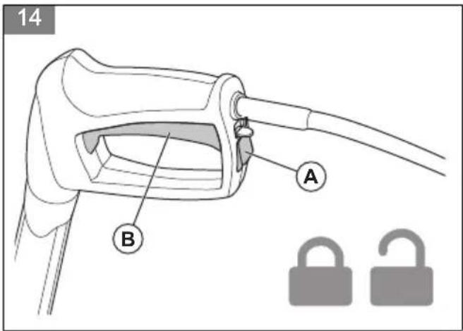
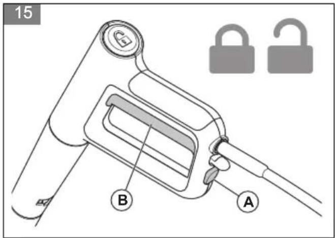
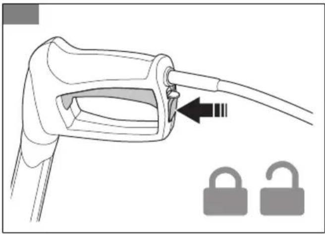
Power trigger lockout
The power trigger lockout (A) prevents accidental operation of the power trigger (B). When the power trigger lockout is in the locked position, the power trigger cannot be pushed in.
- PW 350
(Fig. 14)
• PW 360 and PW 370
(Fig. 15)
Power trigger
The product starts when the power trigger is pushed in. The product stops when the power trigger is released.
Thermal protector
The product has an automatic thermal protector. If the product becomes too hot, the thermal protector will stop the power supply to the product. If the thermal protector has stopped the power, wait until the product is cool. The thermal protector will reset automatically when the product is sufficiently cool.
Hydraulic relief valve
The product has an integrated hydraulic relief valve that prevents too high pressure in the system.
Safety instructions for maintenance

WARNING: Read the warning instructions that follow before you do maintenance on the product.

CAUTION: Always do maintenance before you start the product after a long time in storage.
- Put the power switch in the off (0) position and disconnect the power plug from the power source before you do maintenance on the product.
- Disconnect the product from the water source and make sure that all parts are dry before you do maintenance on the product.
-
Do the maintenance work written in this operator's manual only.
-
Use only spare parts recommended by Husqvarna. High pressure water hoses, fittings and couplings are important for the safety when you operate the product. Use only hoses, fittings and couplings that are recommended by Husqvarna.
- Do not repair the product. Speak to your Husqvarna service agent.
- Speak to your Husqvarna service agent if the power plug or power cord is damaged.
- Do not let children clean or do maintenance on the product.
Assembly
Introduction

WARNING: Read and understand the safety chapter before you assemble the product.
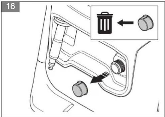
To install the garden hose adapter
- Remove the transport cover from the water inlet and discard it. (Fig. 16)
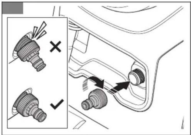
- Install the garden hose adapter on the water inlet.
(Fig. 17)

CAUTION: Make sure that you install the garden hose adapter straight on the water inlet. If the garden hose
adapter is not installed straight, it can cause damage to the threads and leakage can occur.
- Tighten the garden hose adapter fully.
- Remove the garden hose adapter in the opposite sequence.
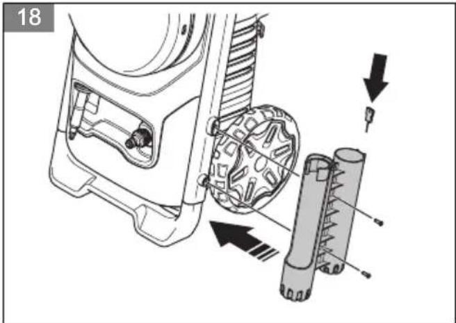
To install the holder for the spray handle and the spray lance
- Put the holder for the spray handle and spray lance in position. (Fig. 18)
- Install the 2 screws.
- Put the cleaning tool in its holder.
Operation
Introduction

WARNING: Read and understand the safety chapter before you use the product.
Husqvarna Connect
Husqvarna Connect is a free app for your mobile device. The Husqvarna Connect app gives extended functions for your Husqvarna product:
- Extended product information.
• Information about, and help with, product parts and servicing.
To start to use Husqvarna Connect
- Download the Husqvarna Connect app on your mobile device.
- Register in the Husqvarna Connect app.
- Follow the instruction steps in the Husqvarna Connect app to connect and register the product.
Note: Husqvarna Connect app is not available for download in all markets. Speak to your servicing dealer for more information.
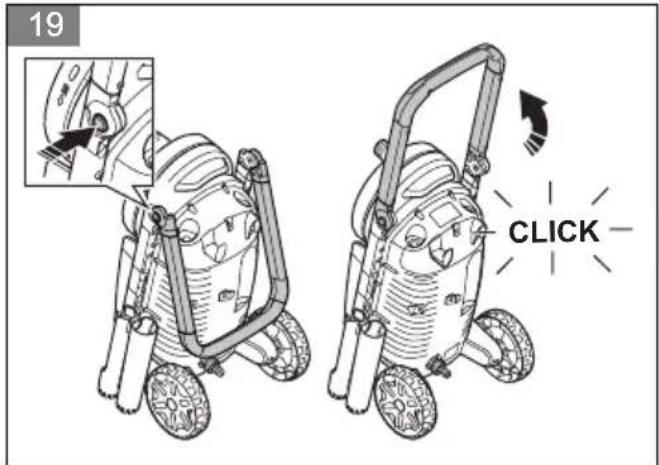
To unfold and fold the transport handle
- To unfold the transport handle, push the buttons on the left and right side and pull up the transport handle. (Fig. 19)
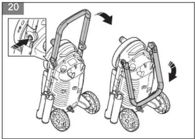
- To fold the transport handle, push the buttons on the left and right side and push down the transport handle. (Fig. 20)
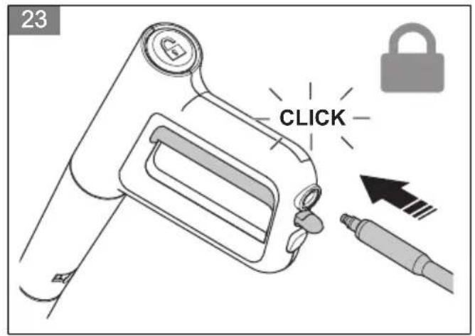
To install the spray handle
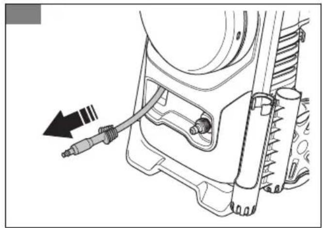
- Pull out the high-pressure water hose. (Fig. 21)
- Hold the spray handle tightly with one hand and push the high-pressure water hose into the quick connection on the spray handle.
a) PW 350 (Fig. 22)
b) PW 360 and PW 370 (Fig. 23)
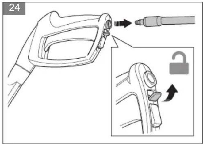
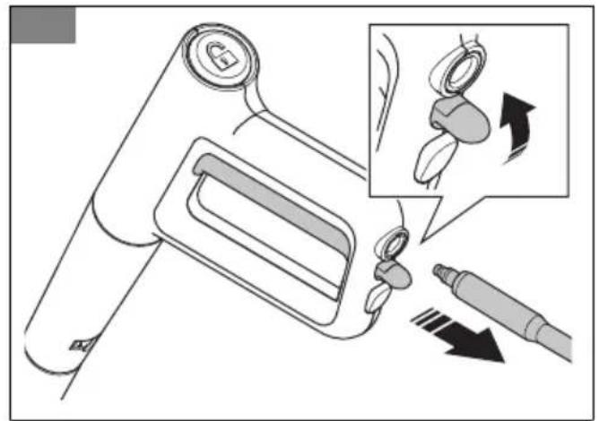
To remove the spray handle
- Push the tab in the direction of the quick connection on the spray handle and pull out the high-pressure water hose.
a) PW 350 (Fig. 24)
b) PW 360 and PW 370 (Fig. 25)
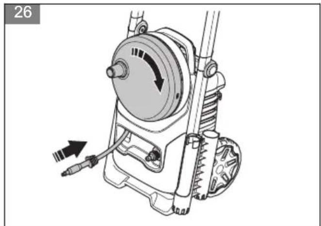
- Turn the hose reel clockwise until the high-pressure water hose is fully wound. (Fig. 26)
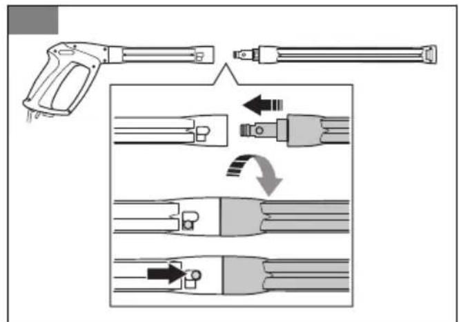
To install the spray lance
- Hold the spray handle with one hand and push the coupling on the spray lance into the spray handle.
a) PW 350 (Fig. 27)
b) PW 360 and PW 370 (Fig. 28)
- Turn the spray lance clockwise and release the spray lance. The spray lance locks in position.
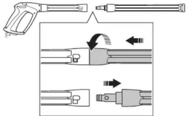
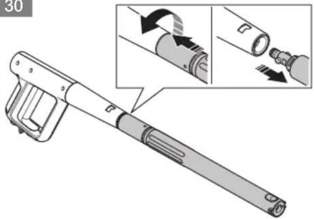
To remove the spray lance
- Push in the spray lance and turn it counterclockwise.
a) PW 350 (Fig. 29)
b) PW 360 and PW 370 (Fig. 30)
- Pull out the spray lance from the spray handle.
Nozzles (PW 350)
The product is supplied with 3 nozzles:
- One nozzle with a rotating water jet, identified with "ROUGH NOZZLE".
- One nozzle with straight water jet, identified with "GENTLE NOZZLE".
- One nozzle with straight water jet, identified with "SHORT NOZZLE".
The nozzle identified with "ROUGH NOZZLE" can be used to clean surfaces that are not sensitive, for example driveways. The nozzle identified with "GENTLE NOZZLE" can be used to clean sensitive surfaces, for example vehicles. The nozzle identified with "SHORT NOZZLE" has a straight water jet with low pressure that can be used to lightly flush a surface. It cannot be installed on the spray lance.
(Fig. 31)
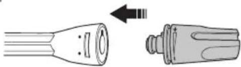
To install and remove a nozzle on the spray lance (PW 350)

CAUTION: Do not use the nozzle with a rotating water jet on sensitive surfaces, for example painted surfaces on a vehicle. The rotating water jet can cause damage to the surface.
- To install a nozzle, hold the spray lance with one hand and push in the nozzle until it locks in position. (Fig. 32)
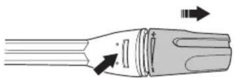
- To remove a nozzle, push in the tab on the spray lance and pull out the nozzle from the spray lance. (Fig. 33)
To adjust the pressure of the water jet (PW 350)
The nozzle with a straight water jet has adjustable pressure.
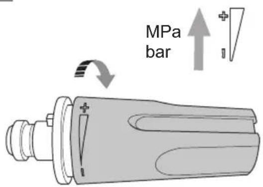
• To increase the pressure of the water jet, turn the nozzle clockwise. (Fig. 34)
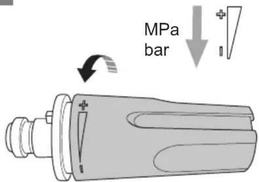
- To decrease the pressure of the water jet, turn the nozzle counterclockwise. (Fig. 35)
To install and remove the short nozzle for the spray handle (PW 350)
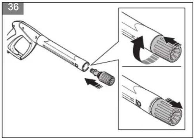
- To install the nozzle, hold the spray handle with one hand and push the coupling on the nozzle into the spray handle. Turn the nozzle clockwise and release the nozzle. The nozzle locks in position. (Fig. 36)
- To remove the nozzle, push in the nozzle and turn it counterclockwise. Pull the nozzle from the spray handle. (Fig. 37)
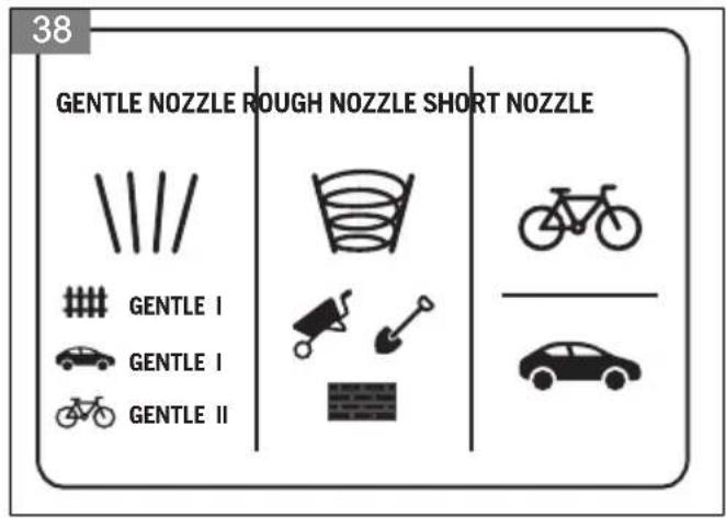
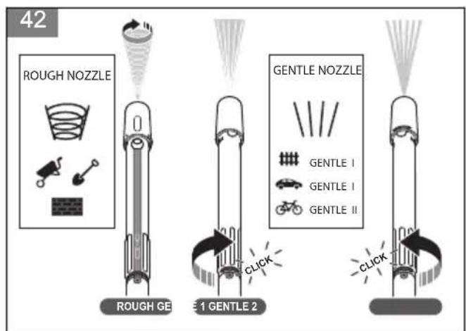
Nozzles (PW 360, PW 370)
The product is supplied with 2 nozzles:
- One 3-in-1 nozzle that can be installed on the spray lance.
- One short nozzle with a straight water jet that can be installed on the spray handle.
The 3-in-1 nozzle has 3 adjustments:
- "ROUGH"
- "GENTLE I"
- "GENTLE II"
The "ROUGH" adjustment has a rotating water jet and can be used to clean surfaces that are not sensitive, for example driveways. The "GENTLE I" adjustment has a straight water jet that can be used to clean sensitive surfaces, for example painted fences. The "GENTLE II" adjustment has a straight water jet that can be used to clean sensitive surfaces, for example vehicles. For PW 370, refer to the display on the product for recommended use.
The nozzle identified with "SHORT NOZZLE" has a straight water jet with low pressure that can be used to lightly flush a surface. It cannot be installed on the spray lance.
(Fig. 38)
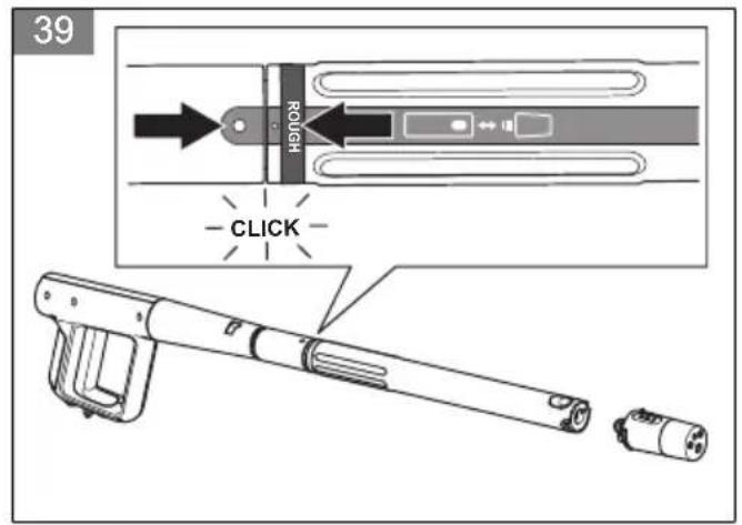
To install and remove the 3-in-1 nozzle for the spray lance (PW 360, PW 370)
- To install the 3-in-1 nozzle, do the steps that follow.
a) Turn the spray lance until the nozzle symbol aligns with the mark on the spray handle. (Fig. 39)
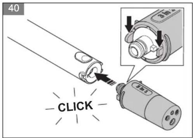
b) Hold the spray lance with one hand and push in the 3-in-1 nozzle until it locks in position. Make sure that you align the tab that has a square shape with the notch that has a square shape. (Fig. 40)
- To remove the 3-in-1 nozzle, do the steps that follow.
a) Turn the spray lance until the nozzle symbol aligns with the mark on the spray handle. (Fig. 39)
b) Push in the button on the spray lance and pull out the 3-in-1 nozzle from the spray lance. (Fig. 41)
To adjust the water jet (PW 360, PW 370)
Note: When the 3-in-1 nozzle is installed on the spray lance, the rotating water jet is selected.

CAUTION: Do not use the rotating water jet on sensitive surfaces, for example painted surfaces on a vehicle. The rotating water jet can cause damage to the surface.
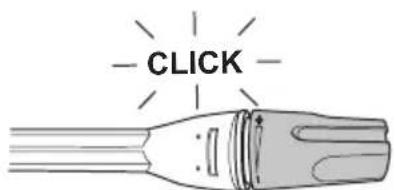
- Turn the spray lance to select the necessary adjustment. The adjustment is selected when you hear a click. (Fig. 42)
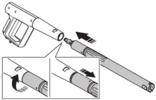
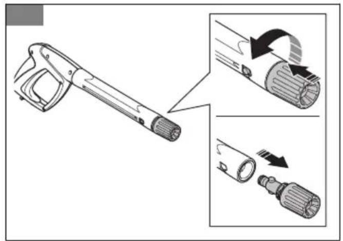
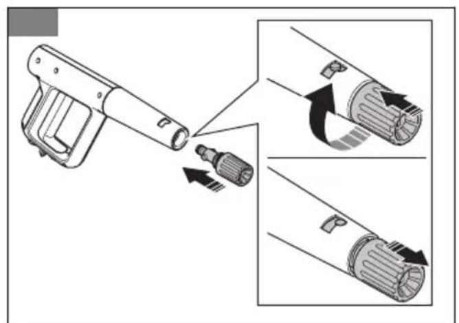
To install and remove the short nozzle for the spray handle (PW 360, PW 370)
- To install the nozzle, hold the spray handle with one hand and push the coupling on the nozzle into the spray handle. Turn the nozzle clockwise and release the nozzle. The nozzle locks in position. (Fig. 43)
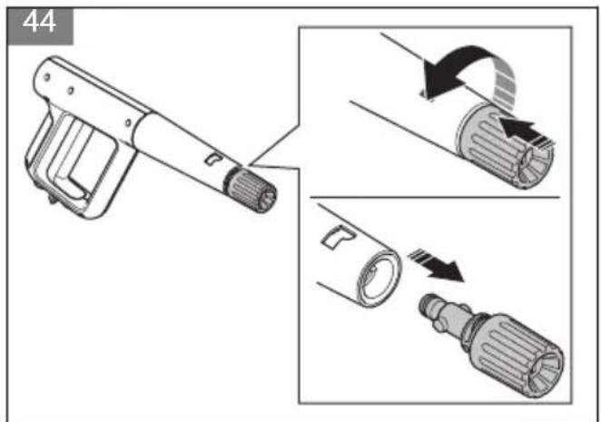
- To remove the nozzle, push in the nozzle and turn it counterclockwise. Pull the nozzle from the spray handle. (Fig. 44)
To operate the product
- Connect the product to a water source. Refer to To connect the product to a water source on page 22.
- Bleed the system. Refer to To bleed the system on page 23.
- Start the product. Refer to To start the product on page 24.
To connect the product to a water source
The product can be used with water from the water mains or water from an open water source, for example a lake or a water barrel.
- To connect the product to the water mains, refer to To connect the product to the water mains on page 22.
- To connect the product to an open water source, refer to To connect the product to an open water source on page 23.
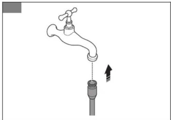
To connect the product to the water mains
- Install the garden hose adapter to the water inlet on the product. Refer to To install the garden hose adapter on page 20.
- Connect the garden hose to the water mains. Use a 12 in. garden hose that is 10–25 m long. (Fig. 45)

CAUTION: The water pressure in the water mains must not be more than 1 MPa (10 bar).

CAUTION: The water temperature in the water mains must not be more than 40^ C.
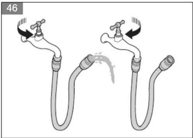
- Open the valve on the water mains and make sure that water can flow freely from the garden hose. (Fig. 46)
- Close the valve on the water mains.
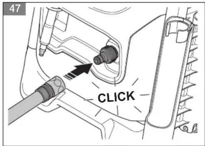
- Connect the garden hose to the water inlet on the product. (Fig. 47)
-
Connect the power plug to the power source.
-
Hold the spray handle tightly with one hand and push the high-pressure water hose into the quick connection on the spray handle.
a) PW 350 (Fig. 22)
b) PW 360 and PW 370 (Fig. 23)
-
Open the valve on the water mains.
-
Bleed the system before you operate the product.
Refer to To bleed the system on page 23.
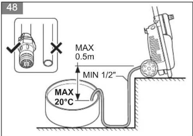
To connect the product to an open water source
The product can be used with water from an open water source, for example a lake or a water barrel. Use a 12 in. suction hose (not included) that is maximum 3 m long.
(Fig. 48)

CAUTION: The water temperature in the water source must not be more than 20^ C.

CAUTION: The product must not be more than 0.5 m above the water source.
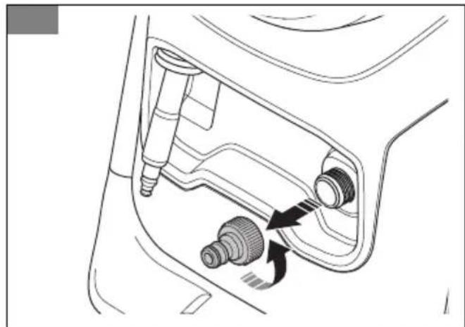
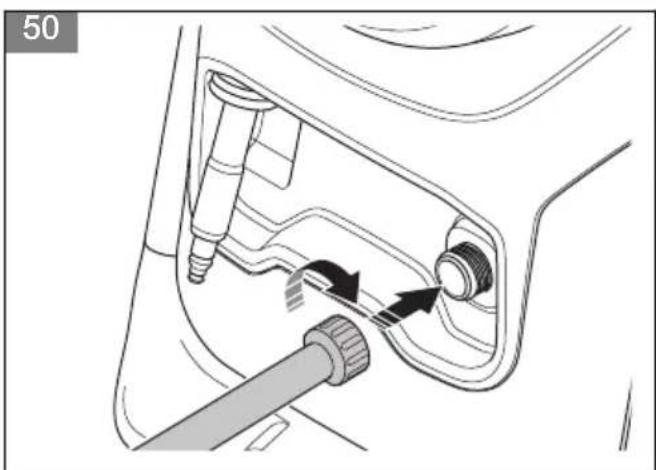
- If the garden hose adapter is installed, remove it from the water inlet on the product. (Fig. 49)

CAUTION: Do not remove the water filter in the water inlet.
-
Connect a suction hose (not included) to the water inlet on the product. (Fig. 50)
-
Put the suction hose in the water source and make sure that the filter is fully submerged.

CAUTION: Do not use a suction hose without a filter.
- Push the tab in the direction of the quick connection on the spray handle and pull out the high-pressure water hose.
a) PW 350 (Fig. 24)
b) PW 360 and PW 370 (Fig. 25)
-
Connect the power plug to a power source.
-
Turn the power switch to the on (l) position and let the product operate for 2 minutes.
-
Turn the power switch to the off (0) position.
-
Hold the spray handle tightly with one hand and push the high-pressure water hose into the quick connection on the spray handle.
a) PW 350 (Fig. 22)
b) PW 360 and PW 370 (Fig. 23)
- Bleed the system before you operate the product.
Refer to To bleed the system on page 23.
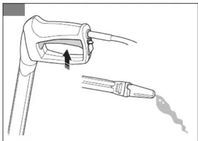
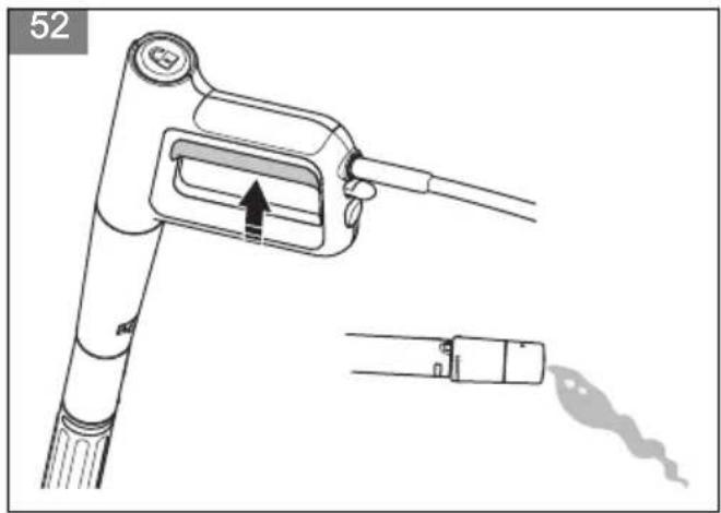
To bleed the system

CAUTION: Make sure that the power switch is in the off (0) position before you bleed the system.
-
Connect the product to a water source. Refer to To connect the product to a water source on page 22.
-
Install the spray lance on the spray handle. Refer to To install the spray lance on page 21.
-
Disengage the power trigger lockout. Refer to To engage and disengage the power trigger lockout on page 23.
-
Push the power trigger and keep it pushed in until water comes out of the nozzle on the spray lance.
a) PW 350 (Fig. 51)
b) PW 360 and PW 370 (Fig. 52)
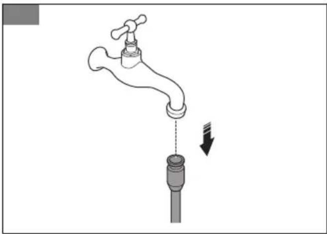
To disconnect the product from the water source
-
Turn the power switch to the off (0) position.
-
If the product is connected to the water mains, close the valve on the water mains.
-
If the product is connected to the water mains, disconnect the garden hose from the water mains. (Fig. 53)
-
If the product is connected to an open water source, remove the suction hose from the water source.
-
Push the power trigger and keep it pushed in until no water comes out of the nozzle.
-
Disconnect the garden hose from the water inlet on the product.
-
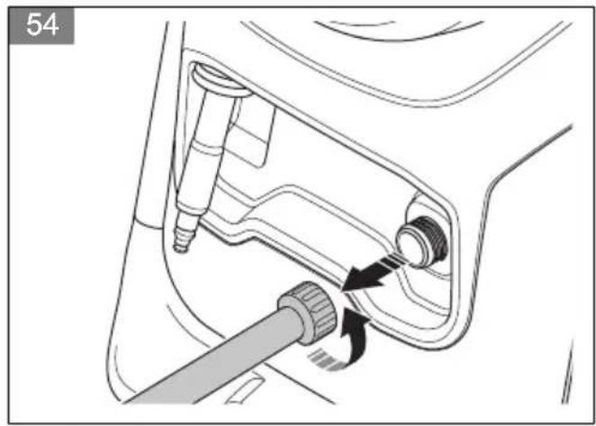
If the product is connected to an open water source, disconnect the suction hose. (Fig. 54)
-
Push the tab in the direction of the quick connection on the spray handle and pull out the high-pressure water hose.
a) PW 350 (Fig. 24)
b) PW 360 and PW 370 (Fig. 25)
-
Turn the power switch to the on (I) position. Let the product operate until no water comes out of the high-pressure hose.
-
Turn the power switch to the off (0) position.
-
Let the spray handle, the spray lance, and the nozzles become dry before you put the product in storage.
To engage and disengage the power trigger lockout
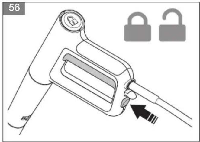
- To engage the power trigger lockout, push the button to the locked position.
a) PW 350 (Fig. 55)
b) PW 360 and PW 370 (Fig. 56)
- To disengage the power trigger lockout, push the button to the unlocked position.
To start the product

CAUTION: Use the product only in upright position. Using the product in horizontal position can damage the product.
- Connect the product to a water source. Refer to To connect the product to a water source on page 22.
- Connect the power plug to a power source.
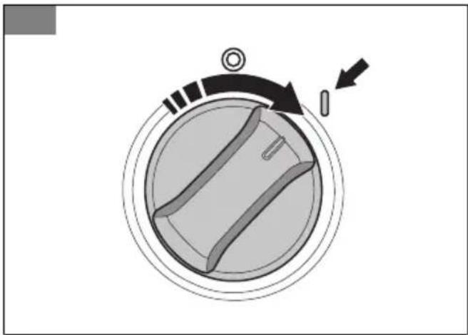
- Turn the power switch to the on (I) position. (Fig. 57)
- Disengage the power trigger lockout. Refer to To engage and disengage the power trigger lockout on page 23.
- Push the power trigger on the spray handle.
Note: The product stops automatically when you release the power trigger.
To stop the product
Note: The product stops automatically when you release the power trigger.
- Release the power trigger on the spray handle.
- Engage the power trigger lockout. Refer to To engage and disengage the power trigger lockout on page 23.
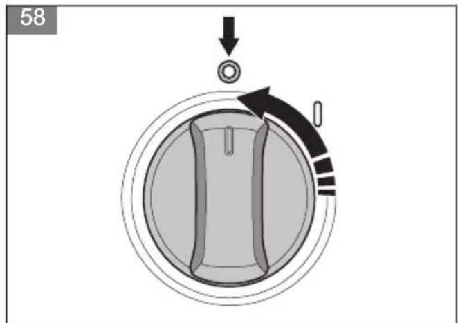
- Turn the power switch to the off (0) position. (Fig. 58)
- Disconnect the power plug from the power source.
- Disconnect the product from the water source. Refer to To disconnect the product from the water source on page 23.
Note: Always disconnect the product from the water source if you go away from the product for more than 5 minutes.
To adjust the angle of the spray handle (PW 360, PW 370)
-
Push the button and turn the handle clockwise or counterclockwise. (Fig. 59)
-
Release the button. The handle locks in position.
To use the foam sprayer (PW 350)
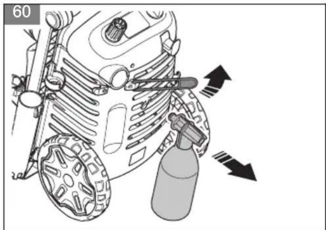
- Remove the foam sprayer from its holder. (Fig. 60)
- Fill the container on the foam sprayer with cleaning agent.

CAUTION: Use only cleaning agents that are recommended by Husqvarna.
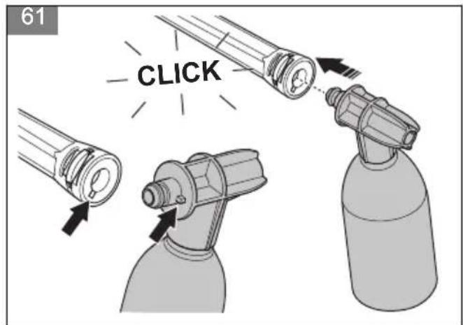
- Push the quick connection on the foam sprayer into the quick connection on the spray lance until it locks in position. The flange on the foam sprayer must align with the groove in the spray lance. (Fig. 61)
- Connect the product to a water source. Refer to To connect the product to a water source on page 22.
- Start the product. Refer to To start the product on page 24.
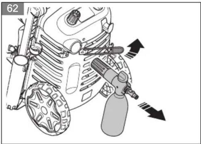
To use the foam sprayer (PW 360, PW 370)
- Remove the foam sprayer from its holder. (Fig. 62)
- Fill the container on the foam sprayer with cleaning agent.

CAUTION: Use only cleaning agents that are recommended by Husqvarna.
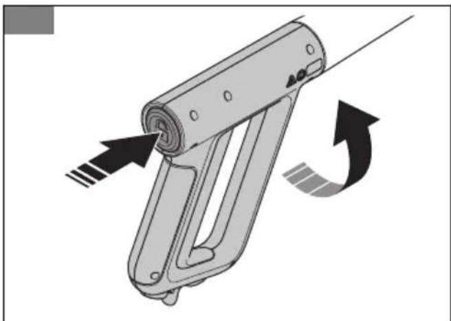
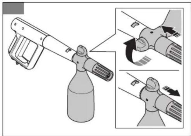
- Push the coupling on the foam sprayer into the spray handle. Turn the foam sprayer clockwise and release the foam sprayer. The foam sprayer locks in position. (Fig. 63)
- Connect the product to a water source. Refer to To connect the product to a water source on page 22.
- Start the product. Refer to To start the product on page 24.
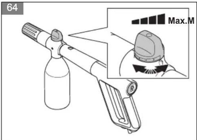
- Turn the knob on the foam sprayer to adjust how much foam is used. Turn the knob clockwise to use more foam. Turn the knob counterclockwise to use less foam. (Fig. 64)
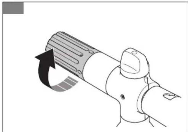
- Turn the nozzle cover to adjust the foam spray pattern. Turn the nozzle cover clockwise for a smaller foam spray pattern or counterclockwise for a wider foam spray pattern. (Fig. 65)
Maintenance
Introduction

WARNING: Before you do maintenance, you must read and understand the safety chapter.
For all servicing and repair work on the product, special training is necessary. We guarantee the availability of professional repairs and servicing.
For more detailed information, refer to www.husqvarna.com.
Maintenance schedule
| Maintenance Before | use | After use | Before storage |
| Do a general inspection. Refer to To do a general inspection on page 25. | X | | |
| Clean the product. Refer to To clean the product on page 25. | | X | |
| Clean the spray lance and the nozzles. Refer to To clean the product on page 25. | | X | |
| Clean the water filter. Replace the water filter if it is damaged. Refer to To clean the water filter on page 26. | | X | |
| Lubricate the O-rings on the couplings. Refer to To lubricate the O-rings on the couplings on page 26. | | X | |
| Clean the filter in the foam sprayer. X | | | |
To do a general inspection

WARNING: Put the power switch in the off (0) position and disconnect the power plug from the power source before you do maintenance on the product.

CAUTION: Disconnect the product from the water source and make sure that all parts are dry before you do maintenance on the product.
• Make sure that the nuts and the screws on the product are tightened.
- Make sure that the cables on the product are not in a position where they can become damaged.
- Examine the high-pressure hose for wear and damage.

WARNING: Do not operate the product if the high-pressure hose is worn or damaged.
To clean the product

WARNING: Put the power switch in the off (0) position and disconnect the power plug from the power source before you do maintenance on the product.

CAUTION: Disconnect the product from the water source and make sure that all parts are dry before you do maintenance on the product.
- Clean all external parts with a dry cloth.
- Do not use a high-pressure washer to clean the product.
- Keep the air inlets clean to make sure that the product always has sufficiently cool temperature.
To clean the spray lance and the nozzles (PW 350)

WARNING: Put the power switch in the off (0) position and disconnect the power plug from the power source before you do maintenance on the product.

CAUTION: Disconnect the product from the water source before you do maintenance on the product.
- If a nozzle is installed on the spray lance, remove it from the spray lance. Refer to Nozzles (PW 350) on page 21.
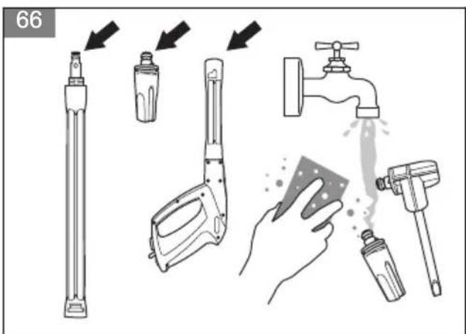
- Clean the nozzles, the coupling on the spray lance, and the coupling on the spray handle with soap and water. (Fig. 66)
- If there is blockage in the nozzles, remove it with the cleaning tool. (Fig. 67)
To clean the spray lance and the nozzles (PW 360, PW 370)

WARNING: Put the power switch in the off (0) position and disconnect the power plug from the power source before you do maintenance on the product.

CAUTION: Disconnect the product from the water source before you do maintenance on the product.
- If a nozzle is installed on the spray lance, remove it from the spray lance. Refer to Nozzles (PW 360, PW 370) on page 22.
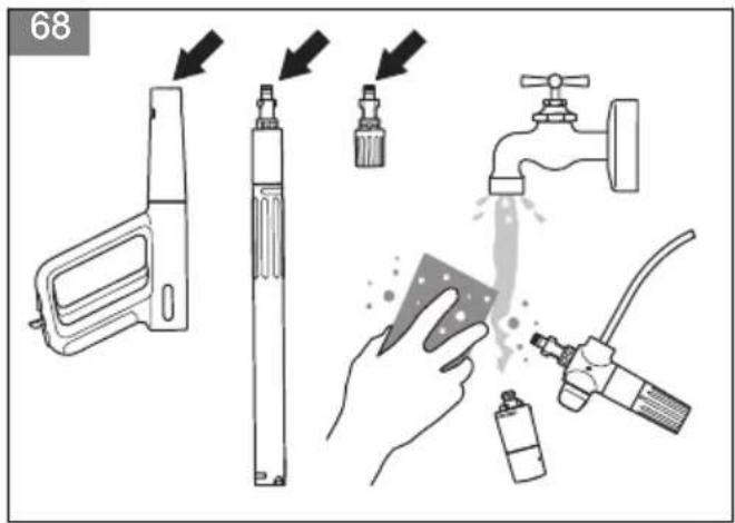
- Clean the nozzles, the coupling on the spray lance, and the coupling on the spray handle with soap and water. (Fig. 68)
- If there is blockage in the nozzles, remove it with the cleaning tool. (Fig. 69)
To clean the water filter

WARNING: Put the power switch in the off (0) position and disconnect the power plug from the power source before you do maintenance on the product.

CAUTION: Disconnect the product from the water source before you do maintenance on the product.
- If the garden hose adapter is installed, remove it from the water inlet on the product. (Fig. 49)
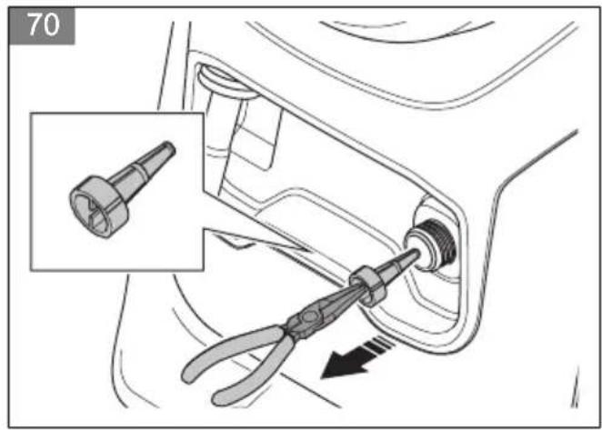
- Pull out the water filter. Use a pair of pliers. (Fig. 70)
- Do a check for damage on the water filter. Replace the water filter if it is damaged. (Fig. 71)
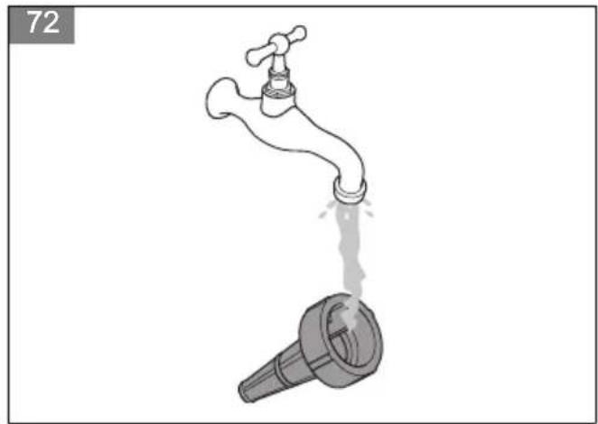
- Flush the water filter with clean water. (Fig. 72)
- Install the water filter in the opposite sequence.
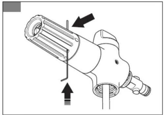
To clean the filter in the foam sprayer
- Carefully push out the pin a small distance with a small hex key or equivalent tool. (Fig. 73)
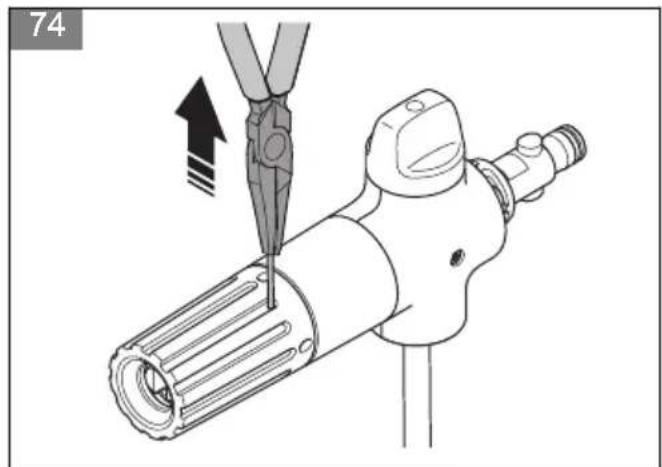
- Pull out the pin with a pair of pliers. (Fig. 74)
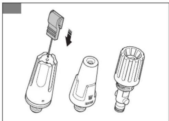
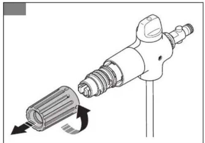
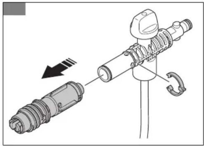
- Turn the nozzle cover counterclockwise and remove it from the foam sprayer. (Fig. 75)
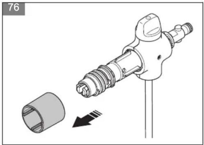
- Remove the ring. (Fig. 76)
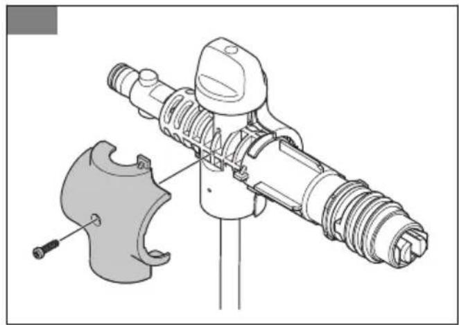
- Remove the screw and the cover on the right side.
(Fig. 77)
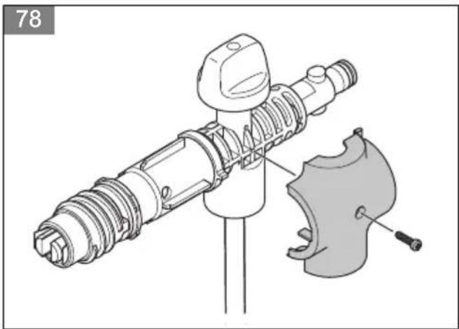
- Remove the screw and the cover on the left side.
(Fig. 78)
- Remove the clip and the nozzle assembly. (Fig. 79)
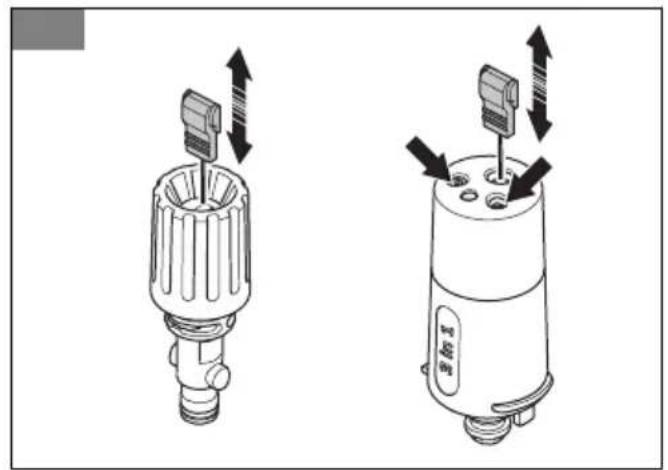
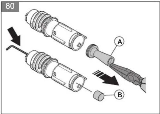
- Pull out the filter holder (A) with a pair of pliers. (Fig. 80)
- Carefully push out the filter (B) with a small hex key or equivalent tool.
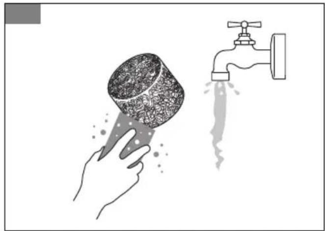
-
Flush the filter with clean water. Replace the filter if it is damaged or cannot be fully cleaned. (Fig. 81)
-
Assemble the foam sprayer in the opposite sequence.
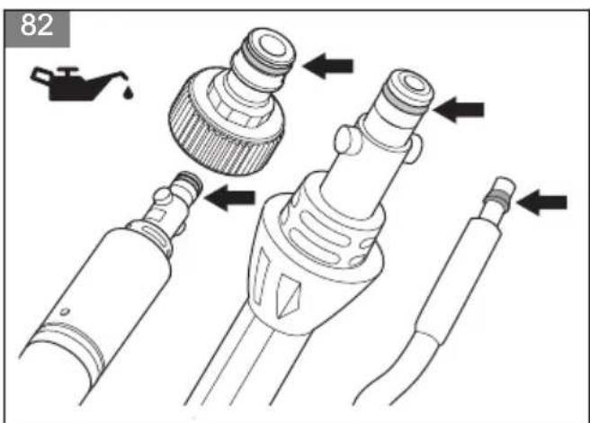
To lubricate the O-rings on the couplings

WARNING: Put the power switch in the off (0) position and disconnect the power plug from the power source before you do maintenance on the product.

CAUTION: Disconnect the product from the water source and make sure that all parts are dry before you do maintenance on the product.
- Remove the spray lance from the spray handle and the spray handle from the high-pressure hose. Refer to To remove the spray lance on page 21 and To remove the spray handle on page 21.
- Lubricate the O-rings on the garden hose adapter, the spray lance, and the high-pressure hose with grease. Refer to Technical data on page 29 for the correct type of grease.
(Fig. 82)
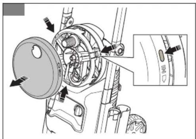
To remove and install the hose reel cover

WARNING: Put the power switch in the off (0) position and disconnect the power plug from the power source before you do maintenance on the product.

CAUTION: Disconnect the product from the water source and make sure that all parts are dry before you do maintenance on the product.
The hose reel cover is attached with 3 snap locks.
- Push in the 3 snap locks and carefully remove the hose reel cover. (Fig. 83)
- To install the hose reel cover, carefully push it until the snap locks locks it in position.
Troubleshooting
Troubleshooting schedule
| Problem Possible cause Solution | | |
| The product does not start. The power | plug is not connected to a power source. | Connect the power plug to a power source. |
| The power switch is in the off (0) position. | Turn the power switch to the on (1) position. |
| There is no electricity in the power source. | Speak to an approved electrician. |
| The power cord is damaged. Speak to | an approved service agent. |
| The thermal protector has stopped the power. | Wait until the product becomes cool before you operate the product again. |
| An incorrect type of extension cable is used. | Make sure that the extension cable is unwound fully and that the voltage supply agrees with the voltage of the product. |
| The display does not start when the power switch is set to the ON (1) position. | The power plug is not connected to a power source. | Connect the power plug to a power source. |
| The fuse blows during start or operation. | An incorrect type of fuse is used. Make sure that you use a slow-blow fuse that has class "C" or "K". |
| The product does not stop. The product is damaged. Disconnect the power plug and speak to an approved service agent. |
| The product becomes too hot. The air flow is not sufficient. Clean the air intakes. |
| The product does not operate smoothly. | There is air in the system. Bleed the system. |
| The water pressure is unsatisfactory. | The hose is bent. Make sure that there are no bends on the hoses. |
| The power switch is in the off (0) position. | Turn the power switch to the on (1) position. |
| The water flow is not sufficient. Make sure that the product is connected to the water source correctly. Make sure that the water flow is sufficient. |
| The water filter is clogged. Clean the water filter. |
| There is air in the system. Bleed the system. |
| The accessory is not correct. Make sure that you use the correct accessory. |
| The high-pressure water hose is not possible to pull out.There is leakage in the couplings. The | The hose reel is blocked. Remove the hose reel cover and remove the blockage. Clean the hose reel.O-rings are worn or damaged. Replace the O-rings. |
Troubleshooting schedule, display (PW 370)
| Problem Possible cause Solution | | |
| Red temperature symbol. Refer to the error message on the display for more information. |  | The ambient temperature in the work area is too low. | Only operate the product when the ambient temperature is 4 °C or more. |
| The ambient temperature in the storage is too low. | Keep the product in a dry and frost-free environment. Make sure that the ambient temperature in the storage is more than 0 °C. |
| The water inlet temperature is too high. | Make sure that the water inlet temperature is max. 40 °C. |
| Red tool symbol. Refer to the error message on the display for more information. |  | The water sensor cannot register the water level. | Stop the product and wait for 5 minutes before you start the product again. If the problem continues, speak to an approved service agent. |
| The temperature sensor cannot register the water temperature. |
| Yellow tool symbol. Refer to the error message on the display for more information. |  | It is recommended to replace the O-rings. | Replace the O-rings. |
| It is recommended to clean the water filter in the water inlet on the product. | Clean the water filter in the water inlet on the product. |
Transportation, storage and disposal
Transportation
- Disconnect the power plug from the power source before transportation of the product.
- Disconnect the product from the water source before transportation of the product.
- Attach the product to prevent movement during transportation.
Storage
- Drain all water from the product, the high-pressure water hose, and the accessories before you put the product in storage. Refer to To disconnect the product from the water source on page 23.
- Prepare the product for storage. Refer to To prepare the product for storage on page 28.
- Keep the product in a dry and frost-free environment.
To prepare the product for storage
- Stop the product and disconnect the power plug from the power source.
- Disconnect the product from the water source. Refer to To disconnect the product from the water source on page 23.
- Make sure that all accessories are dry.
- Put the spray handle, the spray lance, the foam sprayer, and the nozzles in their holders.
-
Disconnect the high-pressure water hose from the spray handle and wind the high-pressure water hose on the hose reel. (Fig. 26)
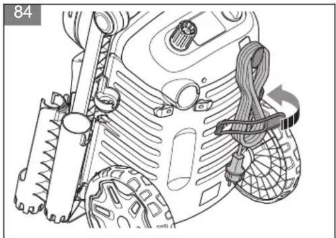
-
Put the power cord on its holder and attach the strap. (Fig. 84)
- Fold the transport handle. Refer to To unfold and fold the transport handle on page 21.
Disposal
The symbol means that the product is not domestic waste. Recycle it through your local collection system for electrical and electronic equipment. This contributes to proper end of life waste management. Contact
local authorities, domestic waste services, your dealer or retailer for information. Incorrect disposal may have potential negative effects on the environment and human health, due to the potential presence of hazardous substances.
(Fig. 13)
Note: The symbol shows on the product or package of the product.
Technical data
| PW 350 PW 360 P | W 370 | |
| Motor and pump |
| Type Series AC Motor Series AC Motor Series AC Motor | | | |
| Power, W 2100 2100 2300 | | | |
| Voltage range, V 230–240 230–240 230–240 | | | |
| Frequency, Hz 50 50 50 | | | |
| Rated current, A 10 10 10 | | | |
| Max. water flow, l/min 7.5 7.5 8.3 | | | |
| Water output pressure, during operation, bar/MPa 125/12.5 | 125/12.5 135/13.5 | | |
| Max. water output pressure, bar/MPa 150/15 | 160/16 | 170/17 | |
| Max. water inlet pressure, bar/MPa | 10/1 | 10/1 | 10/1 |
| Max. water inlet temperature, °C/°F | 40/104 | 40/104 | 40/104 |
| Max. water inlet temperature (in suction mode), °C/°F | 20/68 | 20/68 | 20/68 |
| IP rating | IPX5 | IPX5 | IPX5 |
| Safety class | Class I | Class 1 | Class 1 |
| Lubrication |
| Type of grease for lubrication of O-rings | Universal white silicone grease | Universal white silicone grease | Universal white silicone grease |
| Weight |
| Weight, kg | 21.7 | 22.1 | 22.7 |
| Noise emissions3 |
| Sound power level, measured dB(A) | 86.3 | 86.3 | 86 |
| Sound power level, guaranteed LWA dB(A) | 85±3 85±3 | 86±3 | |
| Sound levels4 |
| PW 350 PW 360 P | PW 370 | |
| Sound pressure level LpA, dB(A) 71.1±2 71.1±2 70.8±2 | | | |
| Vibration levels ^5 |
| Hand/arm (with standard nozzle) m/s ^2 | <2.5 <2.5 <2.5 | | |
Accessories
Approved accessories
| Approved accessories Art. no. | |
| Surface cleaner SC 400 590 65 78-01 | |
| Surface cleaner SC 300 590 65 79-01 | |
| Water filter 590 65 93-01 | |
| Backflow preventer 590 65 95-01 | |
| Suction hose 590 65 97-01 | |
| Foam sprayer FS 400 546 87 18-01 | |
| Foam sprayer FS 300 590 66 04-01 | |
| Water suction nozzle 590 66 05-01 | |
| Rotating brush kit 590 66 06-01 | |
| Vehicle kit 590 66 07-01 | |
| Extension hose, textile reinforced, 8 m 590 66 08-01 | |
| Extension hose, steel reinforced, 10 m 590 66 09-01 | |
| Pipe cleaning hose, 15 m 590 66 10-01 | |
| Angled spray lance 590 66 11-01 | |
| Stone and wood cleaner | 590 66 12-01 |
| Vehicle cleaner and wax | 590 66 13-01 |
| O-ring kit | 591 10 64-01 |
We, Husqvarna AB, SE-561 82 Huskvarna, Sweden, tel: +46-36-146500, declare on our sole responsibility that the product:
| Description Pressure washer | |
| Brand Husqvarna | |
| Type / Model PW 350, PW 360 | |
| Identification Serial numbers | dating from 2023 and onwards |
complies fully with the following EU directives and regulations:
| Regulation Description | |
| 2006/42/EC "relating to machinery" | |
| 2014/30/EU "relating to electromagnetic compatibility" | |
| 2000/14/EC Annex V "relating to the noise emissions in the environment" | |
| 2011/65/EU | “on the restriction of the use of certain hazardous substances in electrical and electronic equipment” |
and that the following standards and/or technical specifications are applied: EN 60335-1:2012/A11:2014/A13:2017/A1:2019/A14:2019/A2:2019/A15:2021, EN 60335-2-79:2012, EN 62233:2008, EN 55014-1:2021, EN 55014-2:2021, EN IEC 61000-3-2:2019/A1:2021, EN 61000-3-3:2013/A2:2021, EN IEC 63000:2018.
For information relating to noise emissions, refer to Technical data on page 29.
Huskvarna, 2023-11-20
$$
\Delta \cdot \mathrm {d u}
$$
Claes Losdal, Development Manager/Garden Products, Husqvarna AB
Responsible for technical documentation
CE
We, Husqvarna AB, SE-561 82 Huskvarna, Sweden, tel: +46-36-146500, declare on our sole responsibility that the product:
| Description Pressure washer | |
| Brand Husqvarna | |
| Type / Model PW 370 | |
| Identification Serial numbers | dating from 2023 and onwards |
complies fully with the following EU directives and regulations:
| Regulation Description | |
| 2006/42/EC "relating to machinery" | |
| 2014/30/EU "relating to electromagnetic compatibility" | |
| 2000/14/EC Annex V "relating to the noise emissions in the environment" | |
| 2011/65/EU | “on the restriction of the use of certain hazardous substances in electrical and electronic equipment” |
and that the following standards and/or technical specifications are applied: EN 60335-1:2012/A11:2014/A13:2017/A1:2019/A14:2019/A2:2019/A15:2021, EN 60335-2-79:2012, EN 62233:2008, EN 55014-1:2021, EN 55014-2:2021, EN IEC 61000-3-2:2019/A1:2021, EN 61000-3-11:2019, EN IEC 63000:2018.
For information relating to noise emissions, refer to Technical data on page 29.
Huskvarna, 2023-11-20
$$
\Delta \cdot 2 m
$$
Claes Losdal, Development Manager/Garden Products, Husqvarna AB
Responsible for technical documentation
CE
Съдържание
Въведение.... 33
Безопасност....35
Монтаж....42
Операция.... 42
Поддръжка....47
BEMÆRK: Sørg for, at
A2:2021, EN IEC 63000:2018.
Claes Losdal, Development Manager/Garden Products, Husqvarna AB
Claes Losdal, Development Manager/Garden Products, Husqvarna AB
- Extended product information.
• Information about, and help with, product parts and servicing.