
PW 130 - Pressure washer HUSQVARNA - Free user manual and instructions
Find the device manual for free PW 130 HUSQVARNA in PDF.

| Product type | Electric pressure washer |
| Brand | Husqvarna |
| Model | PW 130 |
| Power supply | 230 V ~ 50 Hz |
| Power | 1300 W |
| Maximum pressure | 130 bar |
| Water flow rate | 400 L/h |
| Working pressure | 100 bar |
| Motor type | Induction electric |
| Dimensions (L x W x H) | 30 x 25 x 50 cm |
| Weight | 6 kg |
| Hose length | 5 m |
| Hose type | Reinforced high-pressure |
| Included nozzles | Adjustable nozzle and rotary nozzle |
| Detergent tank | 1 L integrated |
| Main functions | High-pressure washing, detergent use, automatic shut-off |
| Noise level | 75 dB(A) |
| Protection class | IPX5 |
| Maintenance and cleaning | Regular cleaning of the water inlet filter, draining after winter use |
| Safety | Anti-start device, child safety on trigger |
| Spare parts | Lance, hose, nozzles, seals |
| Repairability | Repairability index 7.5/10 |
| Warranty | 2 years |
| General information | Designed for domestic cleaning: patios, cars, garden furniture |
Frequently Asked Questions - PW 130 HUSQVARNA
User questions about PW 130 HUSQVARNA
0 question about this device. Answer the ones you know or ask your own.
Ask a new question about this device
Download the instructions for your Pressure washer in PDF format for free! Find your manual PW 130 - HUSQVARNA and take your electronic device back in hand. On this page are published all the documents necessary for the use of your device. PW 130 by HUSQVARNA.
USER MANUAL PW 130 HUSQVARNA
EN Operator's manual 8-24


Contents
Introduction....8
Safety....9
Assembly.... 15
Operation.... 15
Maintenance.... 18
Troubleshooting.... 19
Transportation, storage and disposal.... 20
Technical data.... 20
Accessories.... 22
Declaration of Conformity.... 23
Introduction
Product description
The product is an electrical high-pressure washer. The product can be operated with different levels of water pressure and different cleaning agents.
Intended use
Use the product for domestic cleaning only. Do not use the product for other tasks. Use the product in an upright position only.
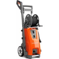
Product overview
(Fig. 1)
- Nozzle with straight water jet
- Nozzle with rotating water jet
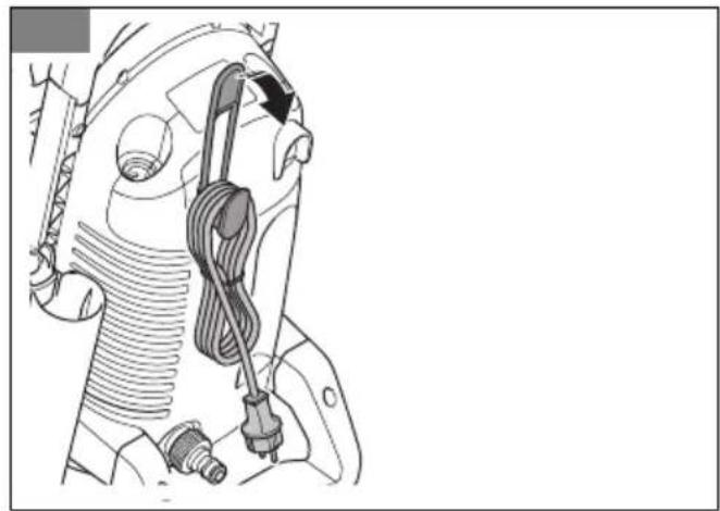
- Rubber strap for power cord holder
- Holder for spray handle and spray lance
- High-pressure water hose
- Water inlet
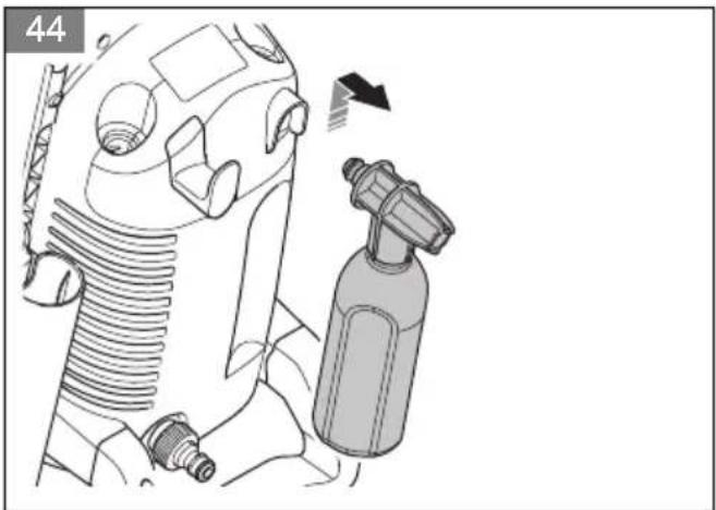
- Foam sprayer
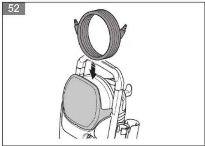
- Storage for high-pressure water hose
- Power switch
- Power cord
- Water outlet with quick connection
- Cleaning tool for nozzles
- Transport handle
- Air intake
- Spray handle
- Spray lance
- Operator's manual
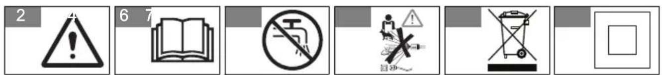
Symbols on the product
(Fig. 2)
WARNING: This product can be dangerous and cause serious injury or death to the operator or others. Be careful and use the product correctly.
Note: National regulations can set limit to the operation of the product.
(Fig. 3)
Read the operator's manual carefully and make sure that you understand the instructions before you use this product.
(Fig. 4)
The product is not suitable for connection to the potable water mains.
(Fig. 5)
High-pressure water jets can be dangerous if subject to misuse. The jet must not be directed at persons, electrical equipment or the product.
(Fig. 6)
Environmental mark. The product or
| package of the product is not domestic waste. Recycle it at an approved disposal location for electrical and electronic equipment. | legislation "Protection of the Environment Operations (Noise Control) Regulations 2017". The guaranteed sound power level of the product is specified in Technical data on page 20 and on the label. | ||
| (Fig. 7) | Class II tool. | ||
| (Fig. 8) | The product agrees with applicable EC directives. | (Fig. 13) | Protected against low pressure water stream from any angle. |
| (Fig. 9) | The product agrees with applicable Eurasian Customs Union directives. | (Fig. 14) | Keep away from frost. |
| (Fig. 15) | This product conforms to the applicable UK regulations. | ||
| (Fig. 10) | The product agrees with applicable UkrSEPRO directives. | ||
| (Fig. 11) | The product agrees with applicable RCM directives. Applies to AU/NZ only. | Note: Other symbols/decals on the product refer to certification requirements for some markets. | |
| (Fig. 12) | Noise emission to the environment label as per EU and UK directives and regulations, and New South Wales | Product liabilityAs referred to in the product liability laws, we are not liable for damages that our product causes if:the product is incorrectly repaired.the product is repaired with parts that are not from the manufacturer or not approved by the manufacturer.the product has an accessory that is not from the manufacturer or not approved by the manufacturer.the product is not repaired at an approved service center or by an approved authority. | |
Safety
Safety definitions
Warnings, cautions and notes are used to point out specially important parts of the manual.
WARNING: Used if there is a risk of injury or death for the operator or bystanders
if the instructions in the manual are not obeyed.

CAUTION: Used if there is a risk of damage to the product, other materials or the adjacent area if the instructions in the manual are not obeyed.
Note: Used to give more information that is necessary in a given situation.
General safety instructions
WARNING: Read the warning instructions that follow before you use the product.
- This product is dangerous if used incorrectly or if you are not careful. Injury or death can occur if you do not obey the safety instructions.
- Always be careful and use your common sense. If you are not sure how to operate the product in a special situation, stop and speak to your Husqvarna service agent before you continue.
- Keep in mind that the operator will be held responsible for
accidents that involve other persons or their property.
- Keep the product clean. Make sure that you can clearly read signs and decals.
- Never allow children or people unfamiliar with these instructions to use the appliance. Local regulations may restrict the age of the operator.
- This product can be operated by persons with reduced physical, sensory, or mental capabilities if they are supervised or given the instructions for how to operate the product safely and understand the hazards involved.
- This product can be operated by persons who do not have the necessary experience or knowledge if they are supervised or given the instructions for how to operate the product safely and understand the hazards involved.
-
Do not use the product if you are tired, ill, or under the influence of alcohol, drugs or medicine. This has a negative effect on your vision, alertness, coordination and judgement.
-
Do not use the product if it is defective.
- Do not change this product or use it if it is possible that it has been changed by others.
Safety instructions for operation
WARNING: Read the warning instructions that follow before you use the product.
- Do not use the product if the power cord, high-pressure hose, trigger lockout or spray handle is damaged.
- Do a check for damage before you operate the product. Do not use the product if parts are damaged or missing.
- Hold the spray handle tightly with both hands. A kickback force occurs when you pull the power trigger.
- Be careful when you operate the product. The high pressure supplied by the product is dangerous and can cause injury.
- Do not point the jet in the direction of you, other persons or animals.
-
Do not point the jet in the direction of yourself or others to clean footwear.
-
Do not point the jet in the direction of electrical equipment or the product itself.
- Use personal protective equipment when you operate the product. Refer to Personal protective equipment on page 13.
- Do not operate the product near persons unless they wear protective equipment.
- If you use a cleaning agent, follow the safety instructions for the cleaning agent.
- Use Husqvarna cleaning agents only.
- Use correct water pressure and cleaning agents, and use the product only for the tasks given in this manual. If you use incorrect water pressure, cleaning agent, or use the product for other tasks than the tasks given in this manual, it can cause damage to the product, surfaces, materials or other devices. Husqvarna does not accept liability for damage that is caused by incorrect use.
- It is not recommended that you connect the product to potable water mains. If you must connect the product to potable water mains, obey local and national regulations.
Use a backflow preventer (not included) if it is necessary. Water that has flowed through a backflow preventer is considered to be non-potable.
- Do not spray flammable liquids. Risk of explosion.
- Do not let children operate the product.
- Do not let children play with the product.
- Do not let persons operate the product without training.
- Use only accessories and spare parts that are approved by Husqvarna.
- Make sure that the electric connection is made by an approved electrician and that it complies with IEC 60364-1.
- Use a residual-current device that stops the electricity if the leakage current is more than 30 mA for 30 ms. If you do not have a residual-current device, use a device that will prove earth circuit.
- Use motor start/delayed fuses with characteristic C or D according to IEC 898-1 or IEC947-2, or corresponding standards outside IEC.
- No actions are needed for adjusting products marked with dual voltage and frequency.
- If it is necessary to use an extension cable, make sure that it is applicable for operation outdoors. Make sure that the socket is at a minimum distance of 60 mm from the ground. The connection must always be kept dry.
- Put the power switch in the off (0) position, disconnect the power plug, and engage the power trigger lockout before you go away from the product.
- Put the power switch in the off (0) position and disconnect the power plug before you change accessory.
- Put the power switch in the off (0) position and disconnect the power plug before you clean or do maintenance on the product.
- Do not operate the product in environments where the ambient temperature is less than 0° C.
- Do not start a frozen product.
- Do not operate the product indoors.
- Do not put objects on the product when it is in operation.
- Do not drink water that has been used with the product.
- Do not operate the product near open windows.
- Watch out for thrown objects. Stones and loose objects can be thrown up into the eyes causing blindness or serious injury.
- If the product does not operate correctly, refer to Troubleshooting schedule on page 19.
Personal protective equipment

WARNING: Read the warning instructions that follow before you use the product.
- Personal protective equipment cannot fully prevent injury but it decreases the degree of injury if an accident does occur. Let your dealer help you select the right equipment.
- Use heavy-duty, slip-resistant, boots or shoes. Do not use open shoes or go with bare feet.
- Use protective clothes.
- Use approved hearing protection.
- Use protective goggles.
- Use breathing protection with class FFP2 or equivalent if you operate the product in environments where
dangerous aerosols can be formed.
Safety devices on the product
WARNING: Read the warning instructions that follow before you use the product.
- Do not use a product with defective safety devices.
- Do not remove or do modifications to safety devices.
- Do a check of the safety devices regularly. If the safety devices are defective, speak to your Husqvarna service agent.
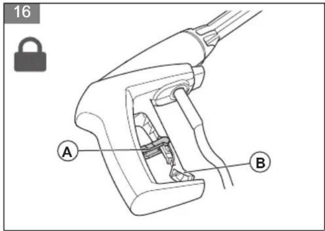
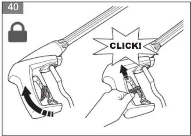
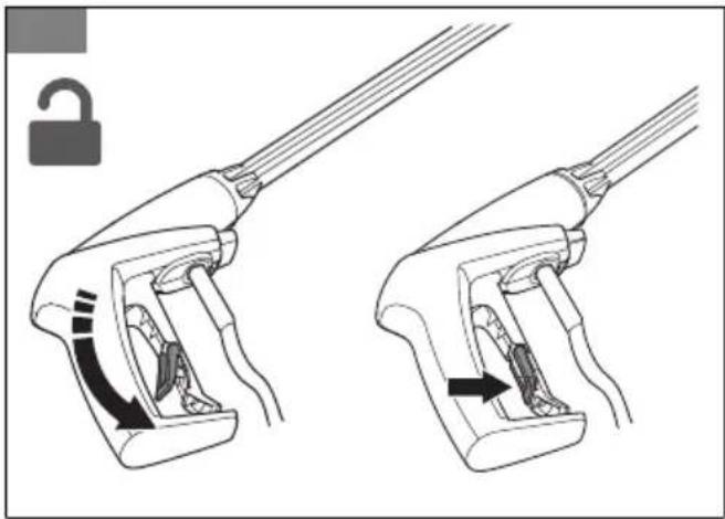
Power trigger lockout
The power trigger lockout (A) prevents accidental operation of the power trigger (B). When the power trigger lockout is in the locked position, the power trigger cannot be pushed in.
(Fig. 16)
Power trigger
The product starts when the power trigger is pushed in. The product stops when the power trigger is released.
Thermal protector
The product has an automatic thermal protector. If the product becomes too hot, the thermal protector will stop the power supply to the product. If the thermal protector has stopped the power, wait until the product is cool. The thermal protector will reset automatically when the product is sufficiently cool.
Hydraulic relief valve
The product has an integrated hydraulic relief valve that prevents too high pressure in the system.
Safety instructions for maintenance
WARNING: Read the warning instructions that follow before you do maintenance on the product.
CAUTION: Always do maintenance before you start the product after a long time in storage.
- Put the power switch in the off (0) position and disconnect the power plug from the power source before you do maintenance on the product.
- Disconnect the product from the water source and make sure that all parts are dry before you do maintenance on the product.
- Do the maintenance work written in this operator's manual only.
- Use only spare parts recommended by Husqvarna. High pressure water hoses, fittings and couplings are important for the safety when you operate the product. Use only hoses, fittings and couplings that are recommended by the manufacturer.
- Do not repair the product. Speak to your Husqvarna service agent.
- Speak to your Husqvarna service agent if the power plug or power cord is damaged.
- Do not let children clean or do maintenance on the product.
Assembly
Introduction

WARNING: Read and understand the safety chapter before you assemble the product.
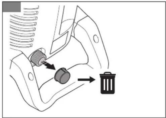
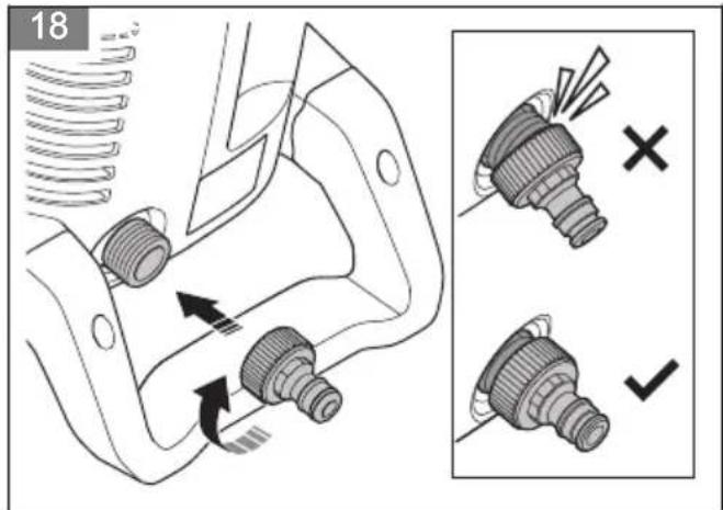
To install the garden hose adapter
- Remove the transport cover from the water inlet and discard it. (Fig. 17)
- Install the garden hose adapter on the water inlet. (Fig. 18)
CAUTION: Make sure that you install the garden hose adapter straight
on the water inlet. If the garden hose adapter is not installed straight, it can cause damage to the threads and leakage can occur.
- Tighten the garden hose adapter fully.
- Remove the garden hose adapter in the opposite sequence.
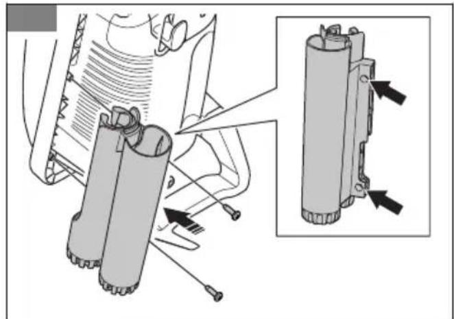
To install the holder for the spray handle and the spray lance
• Install the holder with the 2 screws. (Fig. 19)
Operation
Introduction
WARNING: Read and understand the safety chapter before you use the product.
Husqvarna Connect
Husqvarna Connect is a free app for your mobile device. The Husqvarna Connect app gives extended functions for your Husqvarna product:
- Extended product information.
• Information about, and help with, product parts and servicing.
To start to use Husqvarna Connect
- Download the Husqvarna Connect app on your mobile device.
- Register in the Husqvarna Connect app.
- Follow the instruction steps in the Husqvarna Connect app to connect and register the product.
Note: Husqvarna Connect app is not available for download in all markets. Speak to your servicing dealer for more information.
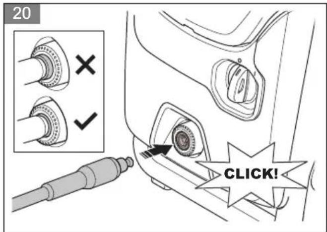
To install the spray handle
- Push the high-pressure water hose into the quick connection until it locks in position. (Fig. 20)

CAUTION: To prevent leakage, make sure that the high-pressure hose
is fully connected to the quick connection on the product.
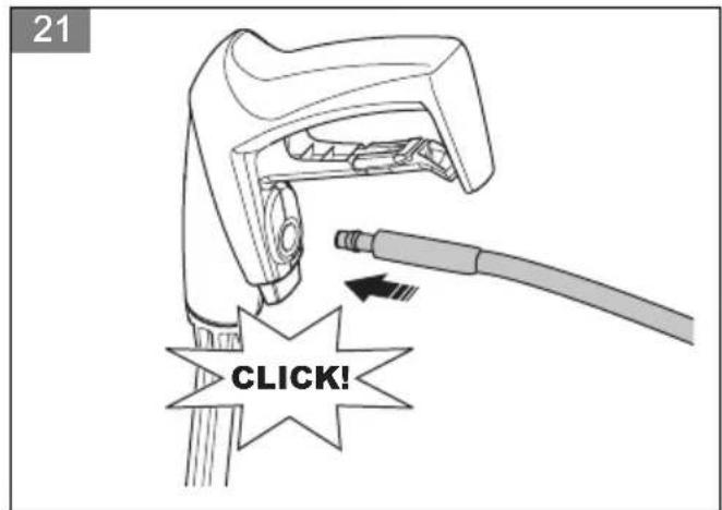
- Hold the spray handle tightly with one hand and push the high-pressure water hose into the quick connection on the spray handle. (Fig. 21)
To remove the spray handle
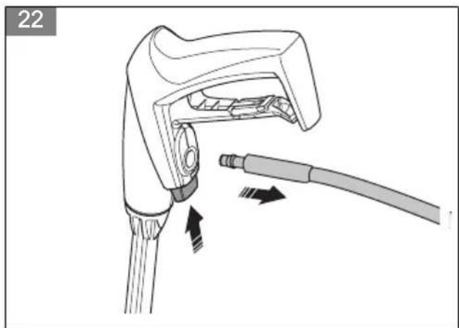
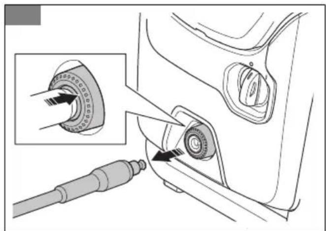
- Push the button on the spray handle and pull out the high-pressure water hose. (Fig. 22)
- Push the outer ring on quick connection and pull out the high-pressure water hose. (Fig. 23)
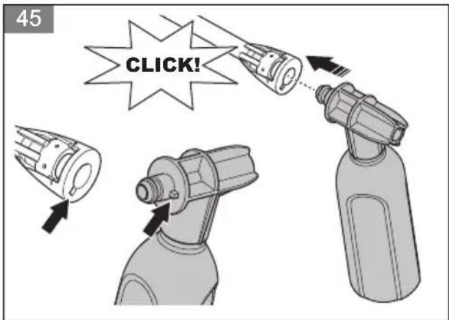
To install the spray lance
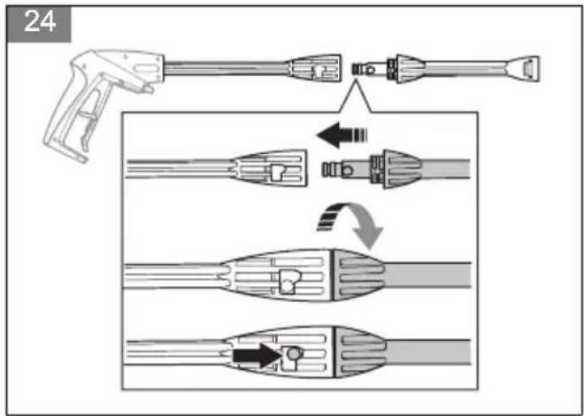
- Hold the spray handle with one hand and push the coupling on the spray lance into the spray handle. (Fig. 24)
- Turn the spray lance clockwise and release the spray lance. The spray lance locks in position.
To remove the spray lance
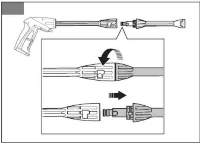
- Push in the spray lance and turn it counterclockwise. (Fig. 25)
- Pull out the spray lance from the spray handle.
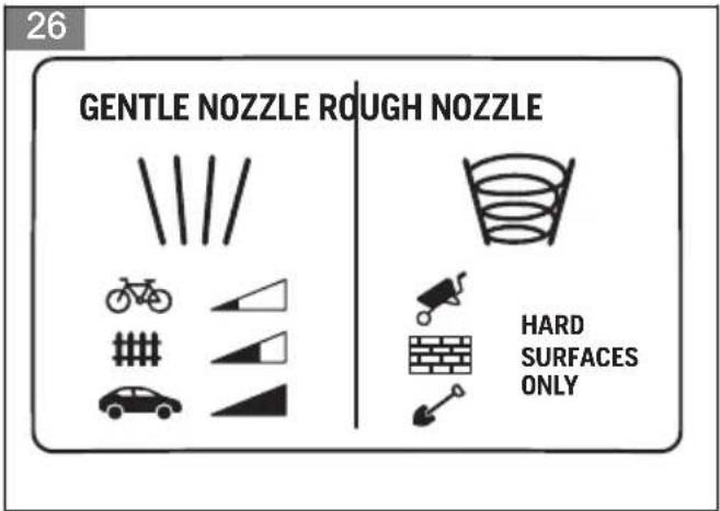
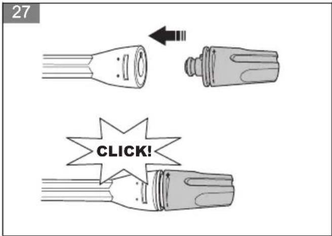
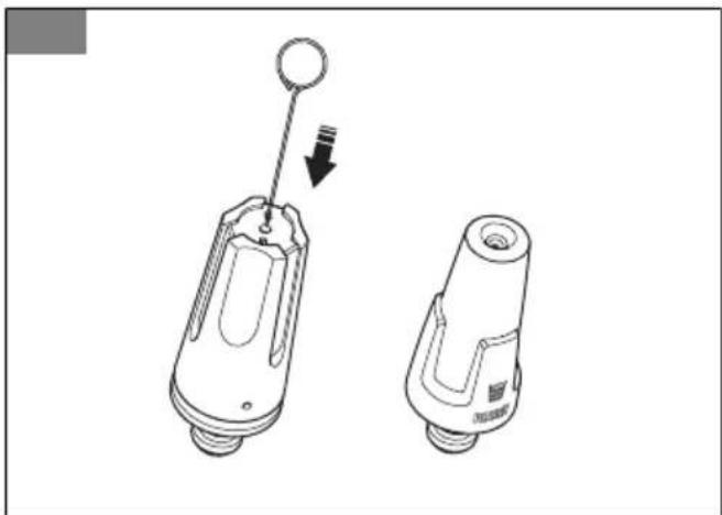
To install and remove a nozzle
The product is supplied with 2 nozzles: 1 nozzle with a straight water jet (identified with "gentle nozzle") and 1 rough nozzle with a rotating water jet (identified with "rough nozzle". The nozzle with a straight water jet can be used to clean sensitive surfaces, for example vehicles. The nozzle can be used to clean surfaces that are not sensitive, for example driveways.
(Fig. 26)
CAUTION: Do not use the nozzle with a rotating water jet on sensitive surfaces, for example painted surfaces on a vehicle. The rotating water jet can cause damage to the surface.
- To install a nozzle, hold the spray lance with one hand and push in the nozzle until it locks in position. (Fig. 27)
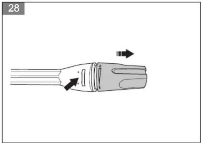
- To remove a nozzle, push in the tab on the spray lance and pull out the nozzle from the spray lance. (Fig. 28)
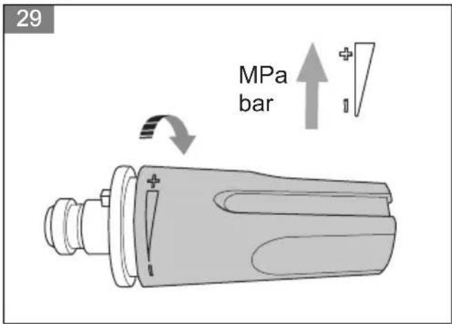
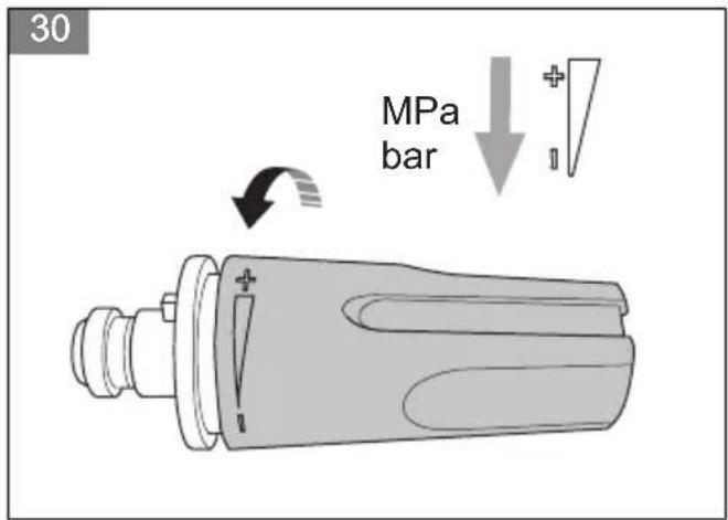
To adjust the pressure of the water jet
The nozzle with a straight water jet has adjustable pressure.
- To increase the pressure of the water jet, turn the nozzle clockwise. (Fig. 29)
- To decrease the pressure of the water jet, turn the nozzle counterclockwise. (Fig. 30)
To operate the product
- Connect the product to a water source. Refer to To connect the product to a water source on page 16.
- Bleed the system. Refer to To bleed the system on page 17.
- Start the product. Refer to To start the product on page 17.
To connect the product to a water source
The product can be used with water from the water mains or water from an open water source, for example a lake or a water barrel.
- To connect the product to the water mains, refer to To connect the product to the water mains on page 16.
- To connect the product to an open water source, refer to To connect the product to an open water source on page 16.
To connect the product to the water mains
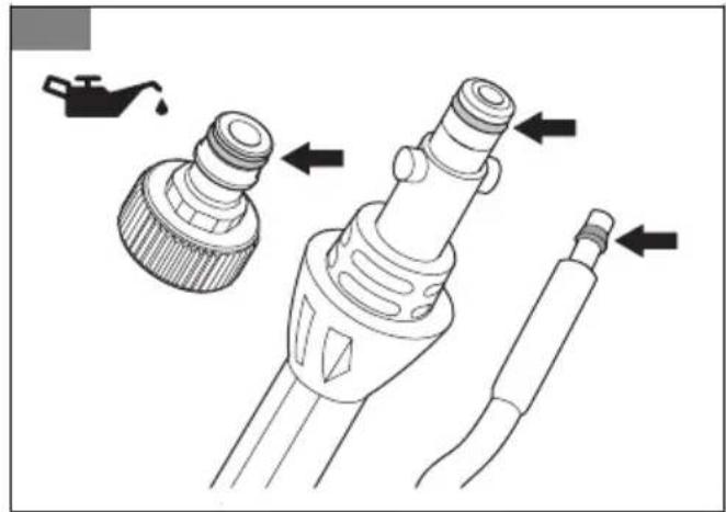
- Install the garden hose adapter and the water filter to the water inlet on the product if they are not installed. Refer to To install the garden hose adapter on page 15.
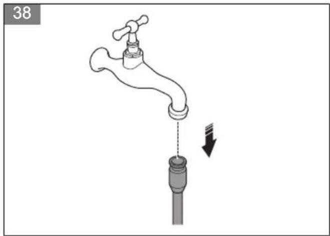
- Connect the garden hose to the water mains. Use a 1/2 in. garden hose that is 10–25 m long. (Fig. 31)
CAUTION: The water pressure in the water mains must not be more than 1 MPa (10 bar).
CAUTION: The water temperature in the water mains must not be more than 40° C.
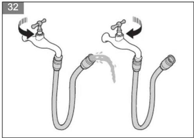
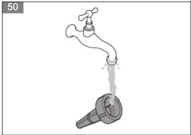
- Open the valve on the water mains and make sure that water can flow freely from the garden hose. (Fig. 32)
- Close the valve on the water mains.
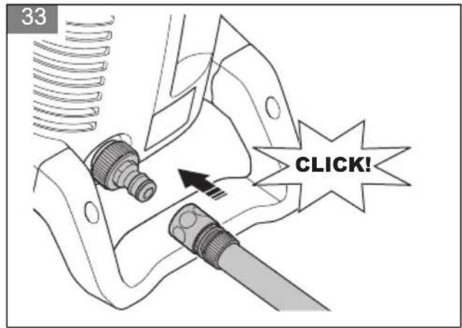
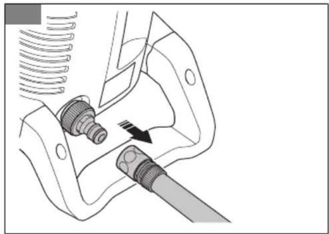
- Connect the garden hose to the water inlet on the product. (Fig. 33)
- Connect the power plug to a power source.
- Open the valve on the water mains.
- Bleed the system before you operate the product. Refer to To bleed the system on page 17.
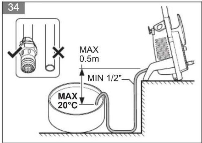
To connect the product to an open water source
The product can be used with water from an open water source, for example a lake or a water barrel. Use a 1/2 in. suction hose (not included) that is maximum 3 m long.
(Fig. 34)
CAUTION: The water temperature in the water source must not be more than 20° C.
CAUTION: The product must not be more than 0.5 m above the water source.
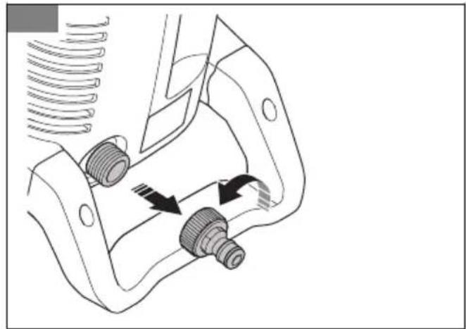
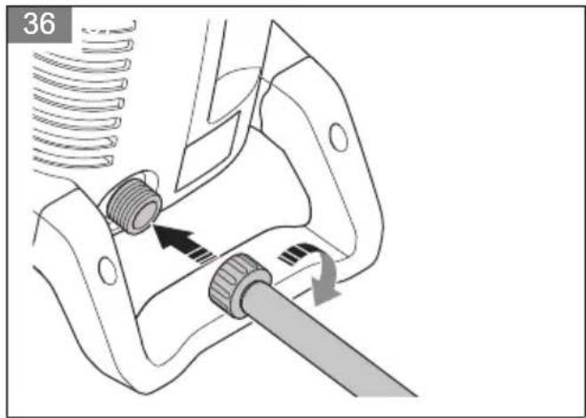
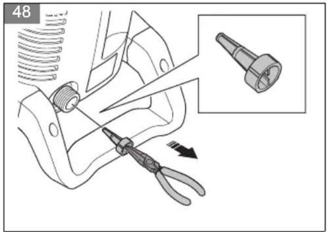
- If the garden hose adapter is installed, remove it from the water inlet on the product. (Fig. 35)
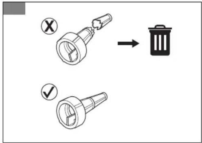
CAUTION: Do not remove the water filter in the water inlet.
- Install a suction hose (not included) to the water inlet on the product. (Fig. 36)
- Put the suction hose in the water source and make sure that the filter is fully submerged.

CAUTION: Do not use a suction hose without a filter.
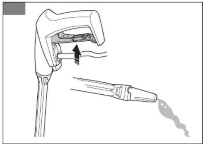
- Push in the button on the spray handle and pull out the high-pressure hose from the spray handle. (Fig. 22)
- Connect the power plug to a power source.
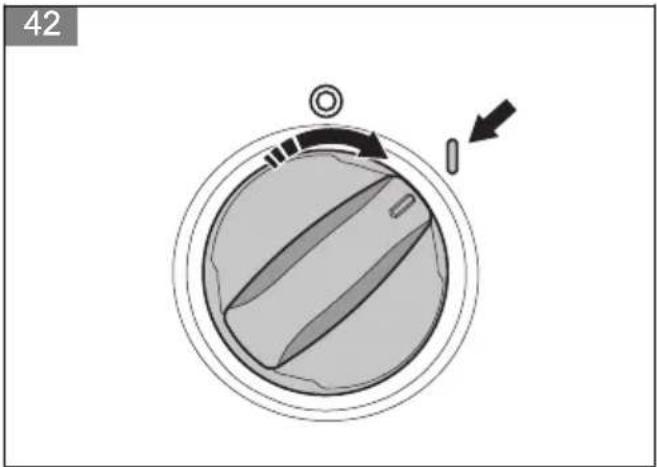
- Turn the power switch to the on (I) position and let the product operate for 2 minutes.
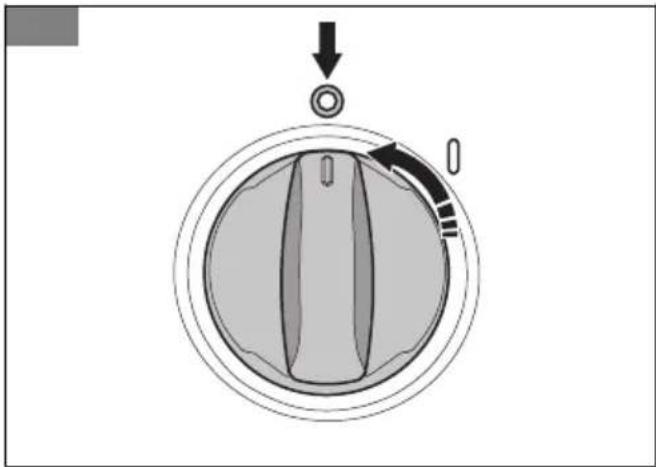
- Turn the power switch to the off (0) position.
- Hold the spray handle tightly with one hand and push the high-pressure hose into the quick coupling on the spray handle. (Fig. 21)


- Contents
- Introduction
- Product description
- Intended use
- Product overview
- (Fig. 1)
- Symbols on the product
- (Fig. 2)
- (Fig. 3)
- (Fig. 4)
- (Fig. 5)
- (Fig. 6)
- Safety
- Safety definitions
- General safety instructions
- Safety instructions for operation
- Personal protective equipment
- Safety devices on the product
- Power trigger lockout
- Power trigger
- Thermal protector
- Hydraulic relief valve
- Safety instructions for maintenance
- Assembly
- To install the garden hose adapter
- To install the holder for the spray handle and the spray lance
- Operation
- Husqvarna connect
- To start to use Husqvarna connect
- To install the spray handle
- To remove the spray handle
- To install the spray lance
- To remove the spray lance
- To install and remove a nozzle
- To adjust the pressure of the water jet
- To operate the product
- To connect the product to a water source
- To connect the product to the water mains
- To connect the product to an open water source
Brand : HUSQVARNA
Model : PW 130
Category : Pressure washer