
KITSPF1 - Washing machine SMEG - Free user manual and instructions
Find the device manual for free KITSPF1 SMEG in PDF.
| Product Type | Stacking kit for washing machine and dryer |
| Brand | SMEG |
| Model | KITSPF1 |
| Use | Allows installing a dryer on top of a washing machine |
| Included parts | Fixing bars (1a, 1b), plastic screws (2), rear support connection piece (3), rear fixing element (4a, 4b), self-tapping screw (5a), Torx screw with bit (5b), aesthetic cover piece (6) |
| Material | Plastic, metal (screws) |
| Compatibility | SMEG washing machine and dryer (check dimensions) |
| Installation | Requires an electric screwdriver and two people to lift the dryer |
| Number of main parts | 6 parts (bars, screws, supports, fixation, aesthetic) |
| Main functions | Attaching dryer to washing machine, stability, aesthetic finish |
| Maintenance | Clean with a damp cloth, avoid solvents |
| Safety | Check stability after installation; use at least two people to lift the dryer |
| Spare parts | Available from SMEG manufacturer or authorized dealers |
| Repairability | Simple mechanical kit, individually replaceable parts |
| General information | Detailed installation manual provided; follow steps to ensure safety |
Frequently Asked Questions - KITSPF1 SMEG
User questions about KITSPF1 SMEG
0 question about this device. Answer the ones you know or ask your own.
Ask a new question about this device
Download the instructions for your Washing machine in PDF format for free! Find your manual KITSPF1 - SMEG and take your electronic device back in hand. On this page are published all the documents necessary for the use of your device. KITSPF1 by SMEG.
USER MANUAL KITSPF1 SMEG
UNIVERSAL STACKING KIT
UNIVERSAL-STAPELSET
KIT DE SUPERPOSITION UNIVERSEL
UNIVERSESTAPELKIT
UNIVERSAL SAMLESAET TIL STABLING
YLEISVALISARJA
UNIVERSELT-STAPELKIT
UNIVERSELLT STAPELPAKET
KIT DE APILAMIENTO UNIVERSAL
Universal Stacking Kit Instruction Booklet
| Part No | Part Name | Part No Part Name | Part No Part Name |
| 1 | Retaining Ducts | 3 | Rear Support Connection Part 5 |
| 2 | Screws | 4 | Rear Fixing Element 6 |
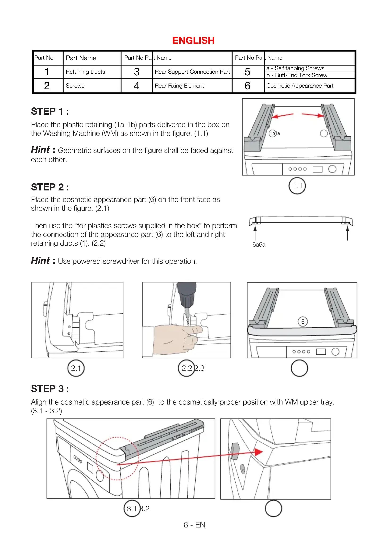
STEP1:
Place the plastic retaining (1a-1b) parts delivered in the box on the Washing Machine (WM) as shown in the figure. (1.1)
Hint : Geometric surfaces on the figure shall be faced against each other.
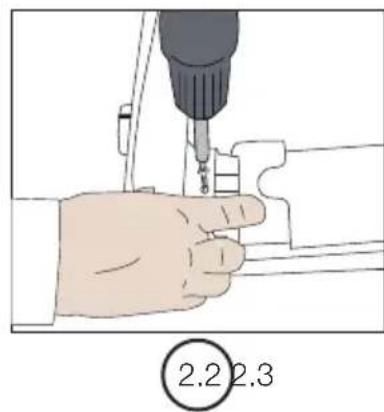
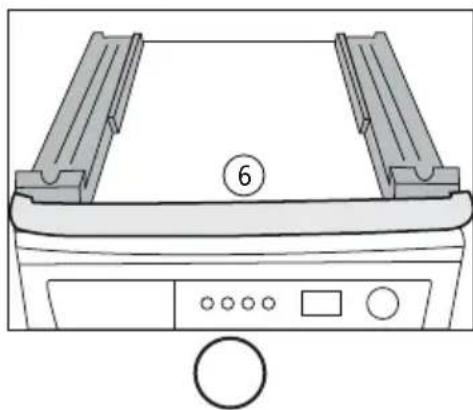
STEP2:
Place the cosmetic appearance part (6) on the front face as shown in the figure. (2.1)
Then use the "for plastics screws supplied in the box" to perform the connection of the appearance part (6) to the left and right retaining ducts (1). (2.2)
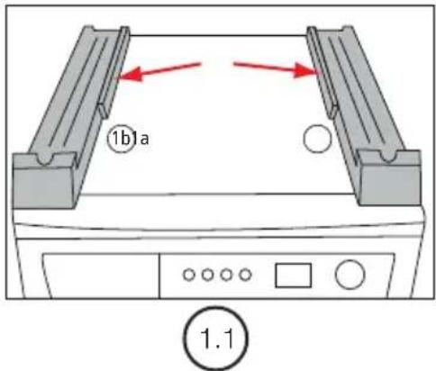
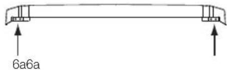
Hint : Use powered screwdriver for this operation.
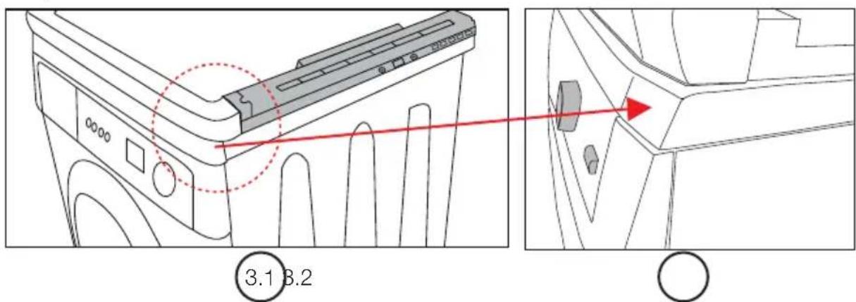
STEP3:
Align the cosmetic appearance part (6) to the cosmetically proper position with WM upper tray. (3.1 - 3.2)
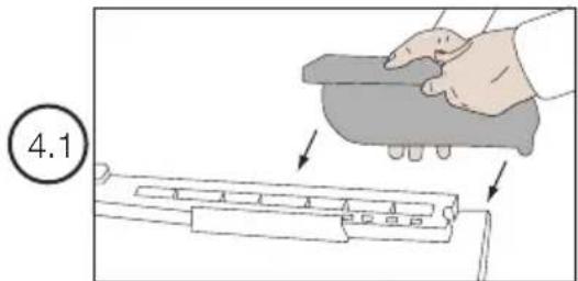
STEP4:
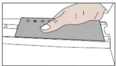
Place the rear support plate (3)
- on the retaining duct (1) as shown in figure 4.1 first. (4.1)
- Then adjust the hole positions on the WM body. (4.2)
Hint 1: As shown in figure 4.3, ensure that it properly seated on the duct shown.
Hint 2: Find the proper screw position (4.4) by moving it on the retaining duct (1) and mount them with the plastic screws (2). (4.5)

4.3
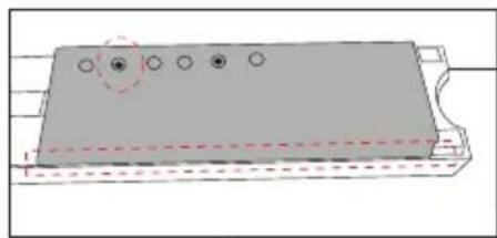
4.4
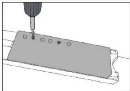
4.5
STEP5:
In order to make the retaining duct (1a-1b) to WM body connection,
- As shown in figure 5.1, use the self tapping screw (5a) delivered with Stacking Kit assembly in order to position the (3a) part on the WM body and perform the connection.

For the connection in this step, special design no. 5a screw is used only and 1 piece is used for the installation. (5.1)
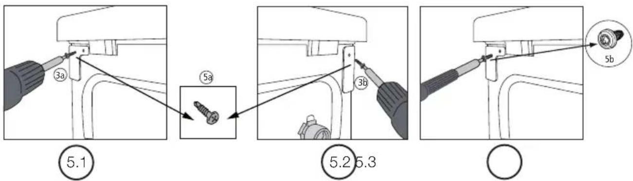
- As shown in figure 5.2, use the self tapping screw (5a) delivered with Stacking Kit assembly in order to position the (3b) part on the WM body and perform the connection.

For the connection in this step, special design no. 5a screw is used only and 1 piece is used for the installation. (5.2)

If there is an installation hole on the body; use butt-end torx screw (5b) instead of drill-bit self-tapping screw (5a). (5.3)
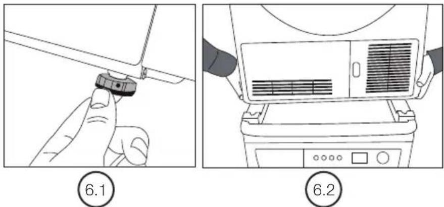
STEP6:
In order to place the Tumble Dryer (TD) on the Washing Machine (WM) and Stacking Kit assembly;

Firstly open 4 adjustable feet of Tumble Dryer (TD) by rotating them for 4-6 turns. (6.1)
- Lift the Tumble Dryer (TD) with two persons at least, and place it on the retaining duct (1). (6.2)

Check the stability of TD after opening the feet.
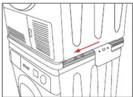
STEP7:
Move the Tumble Dryer (TD) forward on retaining ducts (1). (7.1)
Continue to slide the machine until feet are placed and secured on the duct over the retaining duct (1). (7.2)
7.1
7.2
STEP8:
Remove the PT screws from the reaside body of TD as shown in the figure from left and right side. These screws shall be used later. (8.1)
8.1
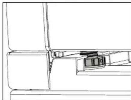
STEP9:
For the connection of TD and Stacking Kit assembly;
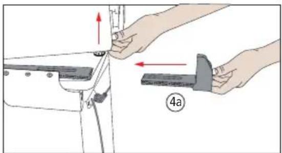
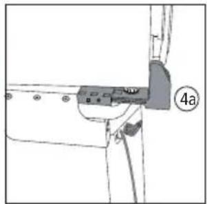
- Lift the TD by pushing it forward from the rear area. Install the rear fixing part (4) to retaining duct (1) part. (9.1)

Rear retaining parts (4a-4b) have two types: left and right. Installation in the reverse direction is not possible. Because rear fixing parts designed as left and right. (4a-4b)
9.19.2
O
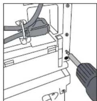
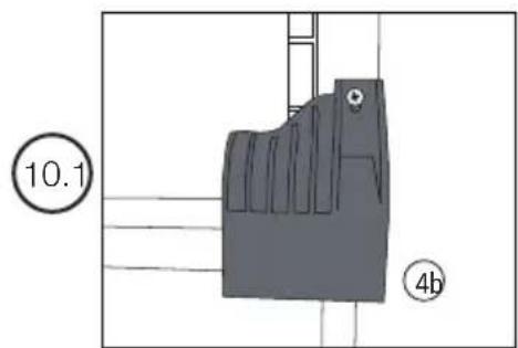
STEP 10:
Move the rear fixing parts (4a-4b) inside the retaining duct (1a-1b) as per the depth of TD.
- After this adjustment, use the screws removed in step 8 to secure rear retaining parts to TD body. (10.1)

Use powered screwdrivers only during screw connection.
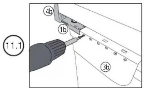
STEP11:
In order to complete the WM, TD and Stacking Kit assembly connections;
- Match the corresponding holes between parts no. 1 and 3 and connect these matching holes (2) with plastic screws. (11.1)
- Complete Stacking Kit installation by making this operation in both directions.
DEUTSCH
- Lift the TD by pushing it forward from the rear area. Install the rear fixing part (4) to retaining duct (1) part. (9.1)
