
Spring 2002 - Barbecue BARBECOOK - Free user manual and instructions
Find the device manual for free Spring 2002 BARBECOOK in PDF.
| Brand | Barbecook |
| Model | Spring 2002 |
| Category | Gas barbecue |
| Product type | Outdoor gas barbecue |
| Power source | Butane or propane gas |
| Number of main burners | 2 (estimated) |
| Ignition | Electric (AA battery) or match |
| Maximum temperature | 300 °C (do not exceed 5 minutes) |
| Main material | Enamel, stainless steel, chrome steel, powder coating |
| Dimensions (H x W x D) | Not specified in the manual |
| Weight | Not specified in the manual |
| Use | Outdoor only |
| Safety | Detailed safety instructions (gas, location, children) |
| Maintenance and cleaning | Regular cleaning of the grid, tank, burners and venturis |
| Warranty | 2 years from purchase date |
| Spare parts | Available at www.barbecook.com |
| Destination country | Europe (different regulators depending on country) |
Frequently Asked Questions - Spring 2002 BARBECOOK
User questions about Spring 2002 BARBECOOK
0 question about this device. Answer the ones you know or ask your own.
Ask a new question about this device
Download the instructions for your Barbecue in PDF format for free! Find your manual Spring 2002 - BARBECOOK and take your electronic device back in hand. On this page are published all the documents necessary for the use of your device. Spring 2002 by BARBECOOK.
USER MANUAL Spring 2002 BARBECOOK
text_image
QR code image containing encoded data, with a central logo or watermarkGO TO WWW.BARBECOOK.COM, REGISTER YOUR BARBECOOK AND YOUR BARBECOOK EXPERIENCE WILL BE FURTHER IMPROVED!
THIS IS YOUR UNIQUE SERIAL N°
[EN] Go to barbecook.com, register your Barbecook and your Barbecook experience will be further improved!
1 Register your appliance....6
2 About this manual....6
3 Important safety instructions....6
- Read and follow the instructions....6
- Be cautious with gas ....6
- Select an appropriate location....6
- Safety warnings ....6
4 Recurrent concepts....6
- Venturis....6
- Burner hoods....7
- Enamel....7
- Flare-ups....7
5 Assembling the appliance....7
- Safety instructions....7
• To assemble the appliance....7
6 Connecting gas to the appliance....7
- Which cylinder, hose and regulator? ....7
- Safety instructions....7
- Connecting the hose to the appliance....7
- Connecting the hose and cylinder to the regulator....8
- Replacing the cylinder ....9
7 Checking for gas leaks 9
• Why check for gas leaks?......9
- When check for gas leaks?......9
- Safety instructions....9
- Which materials do I need? ......9
• To check for gas leaks....9
• In case of a gas leak....9
8 Getting the appliance ready for use....10
• Before each use....10
• Before first use (in a long time .....10
- Burning in the appliance....10
9 Lighting the burners....10
- Safety instructions....10
• Lighting the main burners.....10 - Switching the burners off....11
- Relighting the burners....11
- Checking the flame ....11
10 Useful tips and tricks....12
• Preheating the appliance ....12
- Preventing food form sticking....12
- Direct and indirect grilling....12
- Grilling with closed lid....12
- Watching the temperature ....12
• Taking advantage of the heat zones....12
- Avoiding fla e-ups....12
11 Maintaining the appliance....12
• Cleaning the grill....12
- Cleaning the bowl....12
• Cleaning the burners and venturis......12
- Maintaining enamel, stainless steel, chrome and powder coated parts ....13
• Storing the appliance....13
• Storing gas cylinders 13
- Ordering spare parts....14
12 Warranty....14
- Covered 14
- Not covered ....14
13 Technical specification ....14
- Type label....14
- Injector diameters....14
14 Troubleshooting....15
1 REGISTER YOUR APPLIANCE
Thank you for purchasing a Barbecook appliance! A whole new world is waiting for you to explore, whether it be in the peace and quiet of nature or amidst the hustle and bustle of the city. Become a grill master in our #barbecook community and let us put your grill skills in the spotlight.
Register your Barbecook appliance online and get some major benefits:
- You get access to the full user manual and get to know every bit of your appliance.
- You benefit from a personalized after sales service, allowing you to quickly find spare parts and to profit from an optimal warranty service.
- We inform you about product updates and give you tips, tricks and grillspiration to bring out the grill master in you.
Ready for an adventure? Register your product and join the #barbecook community!

For more information about registering your appliance, refer to www.barbecook.com.

Barbecook respects your privacy. Your data will not be sold, distributed or shared with third parties.
2 ABOUT THIS MANUAL
This manual is composed of two parts:
- The first part is what you are reading now. It includes instructions for the assembly, use and maintenance of your appliance.
- The second part starts on page 295. It includes all kinds of illustrations (exploded views, assembly drawings...) of the appliances that are described in this manual.
3 IMPORTANT SAFETY INSTRUCTIONS
3.1 Read and follow the instructions
Read the instructions before using the appliance. Always follow the instructions carefully. Assembling or using the appliance differently can cause fi es and material damage.

Damages caused by not following the instructions (improper assembly, misuse, inadequate maintenance...) are not covered by the warranty.
3.2 Be cautious with gas
Working with gas is perfectly safe, but requires some extra caution:
- Always store gas cylinders outdoors, in a well-ventilated area. Make sure they are not exposed to excessive heat or direct sunlight.
- Never store your gas cylinder or spare gas cylinder in the cabinet of your appliance.
- Never store your spare gas cylinder near a gas appliance in use.
- Tum off the gas supply at the gas cylinder after use.
- Never smoke near a gas appliance in use of near a gas cylinder (full/empty).

If you smell gas, immediately close the gas supply, extinguish all flames and open the lid of the appliance. If the smell lasts, call your gas supplier or the fi e department.
3.3 Select an appropriate location
Use the appliance outdoors only. Using it indoors, even in a garage or shed, can cause carbon monoxide poisoning.
When selecting an outdoor location, always:
- Place the appliance at least three meters away from any building, in an open and well-ventilated area.
- Make sure there is a free air flow o the burners and the vent holes in the cabinet at all times.
- Make sure the appliance is not under an overhanging structure (a porch, a shelter ...) or under foliage.
- Put the appliance on a firm and stable su face. Never put it on a moving vehicle (a boat, a trailer ...).
3.4 Safety warnings
- Use outdoors only.
- Read the instructions before using the appliance.
- Do not move the appliance during use.
- Do not leave the appliance unattended during use, especially in the presence of children and animals.
- WARNING: accessible parts may be very hot. Keep young children away.
- Use appropriate protection when handling hot parts (lid, grill ...).
- This appliance must be kept away from flammable materials during use.
- Do not use wood, charcoal, lava rocks or ceramic briquettes on a gas appliance.
- Do not use the appliance when you have consumed alcohol or taken drugs.
- Tum off the gas supply at the gas cylinder after use.
- Do not modify the appliance.
4 RECURRENT CONCEPTS
This part includes definitions of some less familiar concepts. These concepts are used in several topics of the manual.
4.1 Venturis
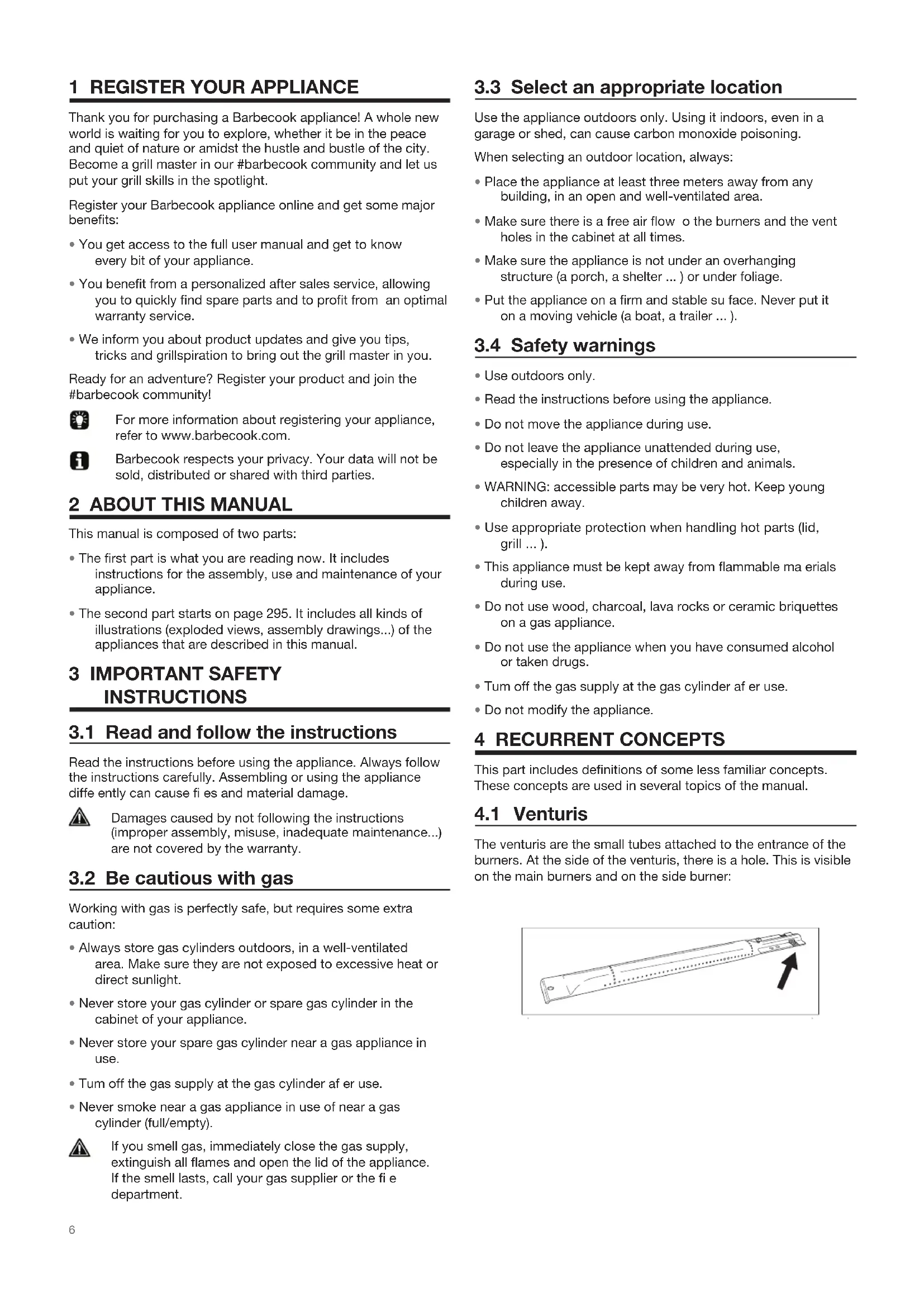
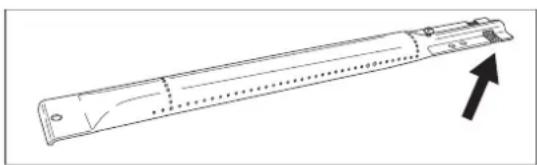
The venturis are the small tubes attached to the entrance of the burners. At the side of the venturis, there is a hole. This is visible on the main burners and on the side burner:
natural_image
Technical line drawing of a mechanical component with an arrow indicating direction (no text or symbols)When the gas is on its way to the burners, it passes through the venturis. Thanks to the holes at the sides, the gas is then mixed with air and - as a result - with oxygen. This is necessary for a good ignition in the burners: only the correct mixture of gas and oxygen will ignite properly and will result in nice flames.
4.2 Burner hoods
The burner hoods are the hoods that you mount above the burners of your appliance. They protect the burners from dripping fat. The holes at the sides of the hoods also distribute the heat over the grill, so it is heated much taster and more evenly.
4.3 Enamel
Some parts of the appliance are covered in a layer of melted glass, called enamel. This enamel protects the underlying metal from corrosion. Enamel is a high-quality material: it is resistant to rust, does not fade under the influence of high temperatures and is very easy to maintain.

Because the enamel is less fl xible than the metal which the appliance incorrectly. To avoid problems, be careful when assembling enamelled parts and always maintain the enamel as described further in this manual.
4.4 Flare-ups
Flare-ups are sudden flames that spark f om the bowl when you are grilling. They are usually caused by dripping fat or marinade.
5 ASSEMBLING THE APPLIANCE
5.1 Safety instructions
- Do not modify the appliance when assembling it. It is very dangerous and not allowed to alter parts that are pre-assembled and/or sealed by the manufacturer.
• Always follow the assembly instructions carefully. - The user is responsible for the correct assembly of the appliance. Damages caused by improper assembly are not covered by the warranty.
5.2 To assemble the appliance
You need a cross-slotted screwdriver, a flat-slot ed screwdriver and an AA battery (electrical igniter). There are no batteries supplied with the appliance.
- Put the appliance on a flat and clean su face.
- Assemble the appliance as shown on the assembly drawings. You find them in the second part of this manual, after the exploded view of your appliance.

Be careful when assembling enamelled parts. The tools and screws may damage the enamel. Use the provided fiber washers to protect the enamel around the screws.

The blister packs can contain more screws than necessary. Screws can be left over after the assembly.

The package includes an emergency kit with spare assembly parts (screws, beits, fiber washers ...) ou can use them in case you lost or broke some parts.
6 CONNECTING GAS TO THE APPLIANCE
6.1 Which cylinder, hose and regulator?
Before you can connect gas to the appliance, you have to buy a gas cylinder, hose and pressure regulator. The table below shows you which cylinder, hose and regulator you have to use. In Belgium (BE), for example, you have to use a propane cylinder with a hose and regulator for 37 mbar or a butane cylinder with a hose and regulator for 28-30 mbar.
| Country | Cylinder, hose and regulator |
| DK, GR, NO, SE, EE, LT, LV, CZ, PL, MT, HU, SI, SK, NL | Propane, 30 mbar / Butane, 30 mbar |
| ES, GB,, IE, PT, BE, FR, LU, IT, CY | Propane, 37 mbar / Butane, 28-30 mbar |

text_image
Technical diagram showing a gas cylinder with height H and diameter D, alongside a mechanical device with cross symbol and warning label.
This barbecue has been adjusted to be operate with 4,5 to 15kg butane/propane cylinders with an appropriate low pressure regulator. We recommend connecting the appliance to propane. Propane offers a high-quality combustion and is less sensitive to frost. The height H of the cylinder must be less than 70~cm , regardless of the cylinder's width or diameter D.

Buy your pressure regulator and gas cylinder together. Not all regulators fit all cylinders

Use only a gas hose and regulator that is homologated for the country of use.
6.2 Safety instructions
- Never connect the cylinder directly to the appliance. Always mount a pressure regulator on the cylinder first
- Never modify pre-assembled or sealed parts of the cylinder, the hose or the pressure regulator.
- Keep the hose as short as possible (1,5 m maximum) to prevent it from dragging on the ground.
- Never distort or twist the hose. Do not pull or pierce the hose. Keep the hose away from any parts of the barbecue that get hot. Check that the fl xible hose stretches out normally, without twisting or pulling.
-
It should be replaced if it is damaged or cracked, when required by national regulations or at the end of the part lifecycle (f.ex France)
-
Never open the gas supply.
• Always keep the cylinder in an upright position. - Check for leaks each time you make changes to the gas connection. See "7 Checking for gas leaks".
6.3 Connecting the hose to the appliance
France:
The equipment may be used with two types of fl xible hose:
- Flexible hose designed to be joined onto ringed tailpieces on both the barbecue and regulator sides, held fir with collars (in accordance with standard XP D 36-110). recommended length 1.25m .
- Flexible hose (according to standard XP D 36-112) fit ed with a G 1/2 threaded nut for fixing o the barbecue and a M 20 x1.5 threaded nut for fixing o the regulator, recommended length 1.25 m.
Other countries:
It should be used with flexible hose that is suitable for use with butane and propane gas. Hose length should not exceed 1.50 m.
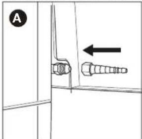
To connect the gas hose to the appliance, you have to mount a coupling on the gas tube of the appliance. The appliance comes with two couplings, both intended for particular countries:
| Country | Coupling |
| BE, CH, CZ, DK, ES, FI, GB, IE, IT, PT, SI | Coupling A |
| FR | Coupling B |

If your country is not in the table, use the coupling that complies with your national standards.

text_image
barbencock6.3.1 C OUPLING A
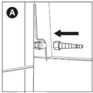
You need a 19 mm spanner and a cross-slotted screwdriver.
- Screw the coupling on the gas tube of the appliance (A) and tighten it with a 19 mm spanner (B).
text_image
A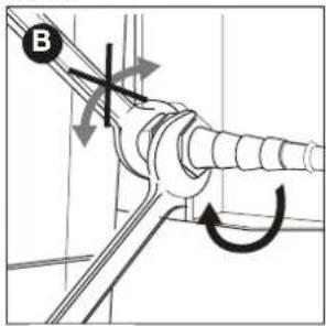
text_image
B- Slide the hose over the coupling (C) and tighten the clamping ring with a cross-slotted screwdriver (D).

natural_image
Technical diagram of a mechanical assembly with a pipe fitting and directional arrow (no text or symbols)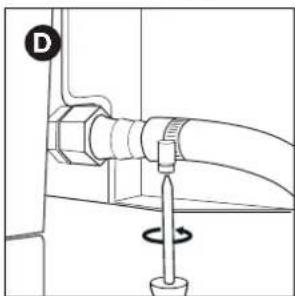
natural_image
Diagram of a mechanical assembly with a rotating knob and pipe connection (no text or symbols)6.3.2 C OUPLING B
You need a 22 mm spanner and an adjustable spanner.
- Screw the coupling on the gas tube of the appliance (A) and tighten it with a 22 mm spanner (B).

natural_image
Pure mechanical diagram showing a pipe fitting with an arrow indicating direction (no text or symbols)
text_image
B- Screw the gas hose on the coupling (C) and tighten it with two spanners. Hold the coupling with a 22 mm spanner, while turning the hose with an adjustable spanner (D).

natural_image
Technical diagram of a mechanical connector with threaded and flanged parts, showing directional arrow (no text or symbols)
text_image
Technical diagram showing pipe connection with rotation arrows and a labeled component 'D'6.4 Connecting the hose and cylinder to the regulator
Depending on the type of pressure regulator you use, you need a cross-slotted screwdriver and/or an adjustable spanner.
-
Connect the hose to the pressure regulator. Do one of the following:
-
If the hose has a clamping ring, slide the hose over the regulator and tighten the clamping ring with a cross-slotted screwdriver (A).
- If the hose has a nut, screw the hose on the regulator and tighten the nut with an adjustable spanner (B).

natural_image
Technical line drawing of a micrometer measuring a cylindrical object (no text or symbols)
natural_image
Technical line drawing of a mechanical assembly with a circular component and a handle (no text or symbols)-
Connect the pressure regulator to the gas cylinder. Do one of the following:
-
If the regulator has a nut, screw the regulator clockwise on the cylinder and tighten the nut with an adjustable spanner (C).
- If the regulator has a screw thread, screw the regulator counter-clockwise on the cylinder (D).

natural_image
Technical line drawing of a mechanical assembly with no visible text or symbols
natural_image
Line drawing of a medical or laboratory setup with a device and tubing (no text or symbols)
Use only regulators complying with EN 16129.
6.5 Replacing the cylinder
- Close the gas supply and set all control knobs to OFF.
- Disconnect the empty cylinder and connect the full cylinder.
- Check the cylinder, the hose and all gas connections for leaks. See "7 Checking for gas leaks".

Attention, when changing the gas cylinder, this should always be carried out away from any source of ignition.
7 CHECKING FOR GAS LEAKS
7.1 Why check for gas leaks?
Propane and butane are heavier than air. As a result, they do not float away when leaking from the appliance. Especially on windless days, a leak can cause the gas to collect in and around the appliance. That accumulated gas can then ignite and explode.
7.2 When check for gas leaks?
- Before the first use or before the first use after a long period of non-use.
Also check for gas leaks if your appliance was assembled by your dealer.
• Each time you replace a gas component. - At least once a year, preferably at the beginning of the season.

7.3 Safety instructions
- Put the appliance outdoors, in a well-ventilated area. Make sure there are no flames or heat sou ces near the appliance.
- Never use a lighter or match to check for gas leaks.
- Do not smoke and do not light the burners when checking for gas leaks.
7.4 Which materials do I need?
To check for gas leaks, you need:
- A testing liquid. You can use a ready-made leak spray or a mixture of water (50%) and dish-washing soap (50%).
- The leak test tool that came with your appliance. You use it to suck up the testing liquid and apply it to the gas component or connection that you want to check.
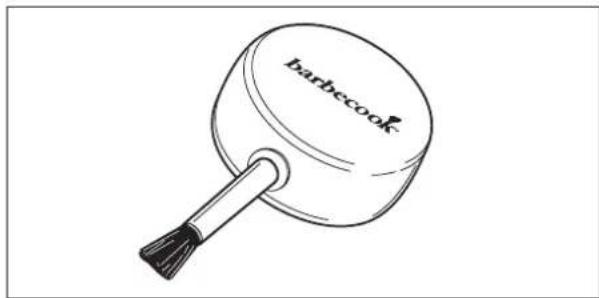
natural_image
Line drawing of a toothbrush with 'barbecook' text on the lid (no other text or symbols)7.5 To check for gas leaks
You check for gas leaks by applying a testing liquid to all gas components and connections. If the bubbles on a particular component or connection grow, there is gas leak:
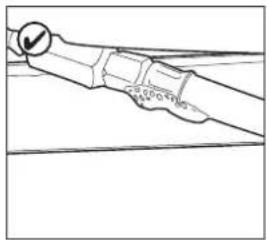
natural_image
Line drawing of a mechanical component with a circular mark and a checkmark (no text or symbols)
natural_image
Diagram of a mechanical or electrical component with no visible text, numbers, or symbolsTo check for gas leaks, proceed as follows:
- Put the appliance outside.
- Get your leak test tool and testing liquid (leak spray or water/soap mixture).
- Open the lid and set all control knobs to OFF.
-
Open the gas supply slightly. Tum the valve of the gas cylinder only once.
-
Suck up some testing liquid with the leak test tool and apply it to the area that you want to check. You have to check:
• The welds of the gas cylinder (A)
- The hose (B)
- The connections between the cylinder and the pressure regulator and between the pressure regulator and the hose (C)
• The connection between the hose and the appliance (D)

natural_image
Line drawing of a gas cylinder with labeled component A and directional arrows (no text or symbols on the diagram itself)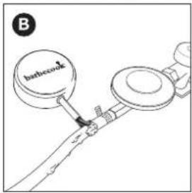
text_image
B barbecock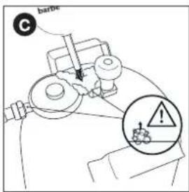
text_image
barble C
text_image
D ! barbecook
Your pressure regulator and coupling may be different from the ones in the illustrations.
-
Do one of the following:
-
If you detect a leak, continue as described in "In case of a gas leak".
- If there are no leaks, close the gas supply, rinse all components thoroughly with water and dry them well.
7.6 In case of a gas leak
-
Close the gas supply and do one of the following:
-
If you detected a leak on one of the connections, tighten that connection.
-
If you detected a leak on the cylinder or hose, replace the cylinder or hose.
-
Recheck the connection or component on which you detected the leak.
- If the leak is not repaired, contact a Barbecook dealer. Do not use the appliance until the leak is repaired.

For a list of nearby Barbecook dealers, refer to www.barbecook.com.
8 GETTING THE APPLIANCE READY FOR USE
8.1 Before each use
Each time you use the appliance, make sure that:
- The appliance is in an appropriate location. See “3.3 Select an appropriate location”.
- The gas hose does not drag on the ground and cannot come into contact with a hot surface or with dripping fat.
- The bowl is clean. We recommend cleaning the bowl after each use. See "11.2 Cleaning the bowl".
- The burners and venturis are not blocked by insect nests or spider webs. See "11.3 Cleaning the burners and venturis".
- The burners are assembled correctly. The venturis have to be placed over the openings of the gas valves.

natural_image
Technical line drawing of a mechanical tool with a lever and shaft, showing no text or symbols
If you want to be absolutely sure that your gas connection is okay, you can check your appliance on gas leaks before each use. See “7 Checking for gas leaks”.
8.2 Before first use (in a long time
If you use the appliance for the first time or for the first time after a long period of non-use, you have to execute some extra checks:
- Make sure that you have read, understood and checked all the instructions in this manual (only before first use)
- Check the appliance for gas leaks. See “7 Checking for gas leaks”.

Also check for gas leaks if your appliance was assembled by your dealer.
- Clean the burners and venturis (only before first use in long time). See “11.3 Cleaning the burners and venturis”.
- Burn in the appliance before you put any food on it (only before first use). See "8.3 Burning in the appliance."
8.3 Burning in the appliance
By burning in the appliance before the first use, you move remaining manufacturing greases from the appliance. Proceed as follows:
- Light the main burners and set their control knobs to HIGH. See "9.2 Lighting the main burners".
- Close the lid and let the appliance burn for 15 minutes. Do not put any food on the grill yet.
- After 15 minutes, open the lid and let the appliance burn for another 5 minutes (control knobs still set to HIGH).
- After 5 minutes, the appliance is ready for use. You can now put food on the grill.
To light the burners with the electrical igniter, you have to install an AA battery in the igniter. That battery is not supplied with the appliance. You find the battery case of the igniter on the control panel of your appliance.
9.1 Safety instructions
- Before you light the appliance, execute all checks listed in "8 Getting the appliance ready for use".
- Make sure the lid is always open when you light a burner.
- Never bend directly over a burner when lighting it.
9.2 Lighting the main burners
9.2.1 U SING THE IGNITER
- Open the lid and set the control knobs of the main burners to OFF.
- If no other burner is lit yet, open the gas supply and wait ten seconds. This allows the gas to stabilize.
- Press the igniter until you hear sparks.
- While holding the igniter, set the control knob of the middle burner to HIGH. Always light the middle burner first, neve try to lit all main burners at the same time.
- If the burner does not light after three attempts, set its control knob to OFF, close the gas supply and wait 5 minutes. This allows any accumulated gas to escape.
- Retry lighting the burner. If it still does not light, try lighting it with a match or refer to "14 Troubleshooting" to determine the cause of the problem.
- Once one burner is lit, light the ether burners by setting their control knobs to HIGH.
9.2.2 U SING A MATCH
- Place a match in the match holder.

natural_image
Simple line drawing of a lever with two circular ends and a fulcrum (no text or symbols)- Open the lid and set the control knobs of the main burners to OFF.
- If no other burner is lit yet, open the gas supply and wait ten seconds. This allows the gas to stabilize.
- Light the match and hold it about 13 mm from the burner.

natural_image
Technical line drawing of a mechanical device with no visible text or symbols- Set the control knob of one burner to HIGH.

Always light one main burner to start with. Never light all main burners at the same time.
- If the burner does not light within 5 seconds, set its control knob to OFF, close the gas supply and wait 5 minutes. This allows any accumulated gas to escape.
- Retry lighting the burner. If it still does not light, refer to "14 Troubleshooting" to determine the cause of the problem.
- Once one burner is lit, light the other burners by setting their control knobs to HIGH.
9.3 Switching the burners off
If you no longer use the burners, you have to switch them off. Proceed as follows:
- Close the gas supply.
- Set the control knobs of the burners to OFF.

By closing the gas supply first, you make sure there is no gas left in the appliance.
9.4 Relighting the burners
If a burner goes out while in use, proceed as follows:
- Open the lid and close the gas supply.
- Set all control knobs to OFF and wait 5 minutes. This allows any accumulated gas to escape.
- Relight the burner(s).
9.5 Checking the flame
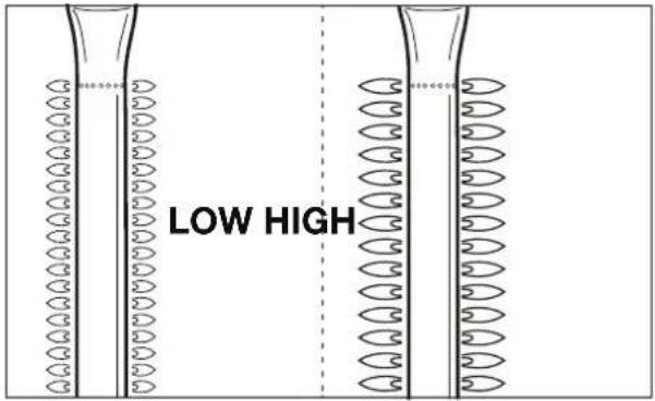
Each time you light a burner, you have to check its flames. A perfect flame is almost completely blue, with some yellow at the top. Sporadic yellow flames are normal and not harmful.
If there is something wrong with the flames, do one of the following to solve the problem:
| If the flames a e... Do the following... | |
| Low and entirely yellow | 1. Immediately close the gas supply and set all control knobs to OFF.2. Refer to “Troubleshooting” to determine the cause of the problem. Most likely, the venturis are blocked. |
| Higher than the bowl | 1. Immediately close the gas supply and set all control knobs to OFF.2. Wait 5 minutes to allow any accumulated gas to escape.3. Relight the burner(s).4. If the problem persists, refer to “Troubleshooting” to determine the cause of the problem. |
text_image
LOW HIGH10 USEFUL TIPS AND TRICKS
10.1 Preheating the appliance
By preheating your appliance, you make sure the grill is hot enough by the time you put food on it. Proceed as follows:
- Light the burner(s) and set their control knob(s) to HIGH.
- Close the lid and leave the appliance for ten minutes.
- After ten minutes, open the lid and put your food on the grill.
- If you need less heat now, set the control knob(s) to a lower position.
10.2 Preventing food from sticking
To prevent your food from sticking to the grill:
- Oil the food lightly with a brush before you put it on the grill. You can also oil the grill itself.
- Preheat the appliance. The warmer the grill when you put food on it, the less the food will stick.
- Do not turn the food too quickly. Let it catch some heat first
10.3 Direct and indirect grilling
Depending on the type of food you are preparing and on how you want to prepare it, you can grill directly or indirectly:
| Method | Description | Use |
| Direct To sear | Red and food directly above a lit burner, set that burner to a high position and keep the lid open. | vegetables |
| Indirect | Put your food next to a lit burner, set that burner to a medium/low position and close the lid. | To further cook seared meat |

When grilling under a closed lid, always keep an eye on the lid thermometer to make sure the appliance does not get too hot. See "10.5 Watching the temperature".
10.4 Grilling with closed lid
Closing the lid while grilling has some important advantages:
- The temperature of the grill is higher and remains more constant.
- You reduce the cooking time of your food and keep your food more moist.
- You reduce fla e-ups and save gas.

When grilling under a closed lid, always keep an eye on the lid thermometer to make sure the appliance does not get too hot. See "10.5 Watching the temperature".
10.5 Watching the temperature
Your appliance is equipped with powerful burners, so it heats up rapidly and you can keep the temperature steady. When grilling under a closed lid, however, you have to make sure that the appliance does not get too hot. Keep an eye on the lid thermometer and take into account the following guidelines:
• A normal cooking temperature is about 210 °C. At higher temperatures, dripping and accumulated fat can ignite.
- The temperature should never be over 300 °C for more than five minutes. This can damage and deform the appliance.

If the appliance gets too hot, cool it down by opening the lid and setting the burners to a lower position.
10.6 Taking advantage of the heat zones
When all burners are lit, the burner hoods distribute the heat as evenly as possible over the grill. Despite this even heating, some zones are still hotter than others. You can take advantage of these heat zones to grill your food to perfection:
| Zone | Hot | Use to... |
| Front Grill | delicate hot food (prawns, fish... | |
| Center | Hotter | Prepare food that needs some time to cook (e.g. sausages, chicken ties...) |
| Back | Hottest | Sear meat and vegetables |

You can also create heat zones by playing with the power of the burners. You can, for example, set a burner to a lower position and use the zone above that burner for delicate food or food that needs some time to cook.
10.7 Avoiding fla e-ups
During grilling, some fla e-ups are normal. Too many fla e-ups, however, increase the temperature in the appliance and can ignite accumulated fat. To avoid fla e-ups:
- Make sure the bowl is clean when you start grilling. We recommend cleaning the bowl after each use. See "11.2 Cleaning the bowl".
- Regularly check if the fat drain hole is not blocked and if the fat drip tray or cup is not full yet.
- When grilling fatty meat, trim excess fat, close the lid and set the burners to a medium or low position.
11 MAINTAINING THE APPLIANCE
11.1 Cleaning the grill
We recommend cleaning the grill after each use, with a Barbecook cleaner.

You can also clean the grill with a soft detergent or with sodium bicarbonate. Never use oven cleaners on the grill.
11.2 Cleaning the bowl
We recommend cleaning the bowl after each use, with a Barbecook cleaner. Use it the same way you do on the grill.
11.3 Cleaning the burners and venturis
11.3.1 WHY CLEAN THE BURNERS AND VENTURIS?
Spiders and insects can make webs and nests in the burners and venturis. This may block the gas supply to the burners. As a result:
- You cannot light the burners. If you manage to light them anyway, they will only produce smoky and yellow flames
- The gas can start burning outside the venturis, at the control knobs. These fi es are called flash-backs and can esult in serious injuries and material damage.

natural_image
Diagram of a fish-shaped object with internal structures and no visible text or symbols
Damages caused by blocked burners and venturis are regarded as inadequate maintenance and are not covered by the warranty.
11.3.2 WHEN CLEAN THE BURNERS AND VENTURIS?
You have to clean the burners and venturis of your appliance:
- Before the first use after a long period of non-use.
- At least twice a year, of which once at the beginning of the season.
11.3.3 TO CLEAN THE BURNERS AND VENTURIS
- Remove the burners from the appliance as shown on the illustrations. If you notice that a burner is damaged, you have to replace it.

natural_image
Technical line drawing of a mechanical assembly with internal components and directional arrows (no text or symbols)- Clean the burners and venturis with a small brush or a homemade pipe cleaner (an unfolded paperclip, a pipe brush ...).
- Put the burners back. Make sure to place the venturis over the openings of the gas valves.
11.4 Maintaining enamel, stainless steel, chrome and powder coated parts
The appliance is composed of enamelled, stainless steel, chromed and powder coated parts. Each material has to be maintained differently:
| Material How to maintain this material | |
| Enamel | Do not use sharp objects and do not knock against a hard surface.Avoid contact with cold liquids while still hot.You can use metal sponges and abrasive detergents. |
| Stainless steel and chrome | Do not use aggressive, abrasive or metal detergents.Use soft detergents and let them act on the steel.Use a soft sponge or cloth.Rinse thoroughly after cleaning and dry well before storing. |
| Powder coated | Do not use sharp objects. Use soft detergents and a soft sponge or cloth.Rinse thoroughly after cleaning and dry well before storing. |

To prevent formation of rust on stainless steel, avoid contact with chlorine, salt and iron. We recommend not using the appliance near the coast, near railways or near swimming pools.

Damages caused by not following these instructions are regarded as inadequate maintenance and are not covered by the warranty.
Below the exploded view of your appliance (second part of the manual), you find a list with all parts of which the appliance is composed. This list includes a symbol that specifies the material of each part, so you can use it to check how you have to maintain a particular part. The parts list uses the following symbols:
| Symbol | Material |
| ● | Enamel |
| ▲ | Chrome |
| ■ | Stainless steel |
| ★ | Powder coated |
11.5 Storing the appliance
If you do not use your appliance for a longer period of time, store it in a dry place. Before you store the appliance:
- Disconnect the gas cylinder. Never store your appliance indoors (not even in a garage or shed) as long as it is connected to the gas cylinder.
- Clean the burners and the grills, rub them with oil and wrap them in paper.
- Cover your appliance with a Barbecook cover. Register your appliance at www.barbecook.com to find out which cove you need.
11.6 Storing gas cylinders
These instructions apply to both empty and full gas cylinders.
- Always store gas cylinders outdoors, in a well-ventilated area. Make sure they are not exposed to excessive heat or direct sunlight.
- Never store a gas cylinder in an area that can become very hot (in a car, on a boat...).
- Never store your gas cylinder or spare gas cylinder in the cabinet of your appliance.
- Never store your spare gas cylinder near a gas appliance in use.
• Always store gas cylinders outside the reach of children.
• Always store and transport gas cylinders in upright position
11.7 Ordering spare parts
Parts that are directly exposed to fire or intense heat have to be replaced from time to time. To order a spare part:
- Look up the reference number of the part you need. You find a list of all reference numbers below the exploded views in the second part of this manual and on www.barbecook.com.

If you registered your appliance online, you will automatically be guided to the correct list in your MyBarbecook account. There you have the possibility to order your parts online.
- Order the spare part via www.barbecook.com or at your point of sale. Parts under warranty can only be ordered at your point of sale.
12.1 Covered
Your appliance comes with a warranty of two years, starting from the date of purchase. This warranty covers all manufacturing defects, provided that:
- You used, assembled and maintained your appliance according to the instructions in this manual. Damages caused by misuse, incorrect assembly or inadequate maintenance are not regarded as manufacturing defects.
-
You can present the receipt and the unique serial number of your appliance. This serial number starts with a G, followed by 15 digits. You can find it:
-
On this manual.
- On the packaging of the appliance.
- On the inside of the bottom front panel.
- The Barbecook quality department confirms that the parts are defective and that they proved defective under normal use, correct assembly and adequate maintenance.
If one of the above conditions is not met, you cannot claim any form of contribution. In all cases, the warranty is limited to the repair or replacement of the defective part(s).
12.2 Not covered
The following damages and defects are not covered by the warranty:
- Normal wear and tear (rusting, distortion, discolouration...) of parts that are directly exposed to fire or intense heat. It is normal to replace these parts from time to time.
- Visual irregularities that are inherent to the manufacturing process. These irregularities are not regarded as manufacturing defects.
- All damages caused by inadequate maintenance, incorrect storage, improper assembly or modifications made to pre-assembled parts.
- All damages caused by misuse and abuse of the appliance (not using it according to the instructions in this manual, using it for commercial purposes, using it as a fire basket...).
- All consequential damages caused by careless or non-compliant use of the appliance.
- Rust or discolouration caused by external influences, the use of aggressive detergents, exposure to chlorine... These damages are not regarded as manufacturing defects.
13.1 Type label
The type label lists all the technical specifications of your appliance. You can find it
• In the second part of this manual.
- On the inside of the bottom front panel
13.2 Injector diameters
- Main burner: 0.95
| Problem Probable cause(s) Solution(s) | ||
| Not enough heat | Gas supply not openVenturis not placed over openings of gas valvesBurner openings blockedGas cylinder (almost) emptyPressure regulator not connected correctly to cylinder and/or hose | Open gas supplyPlace venturis over openings of gas valvesClean burner openings or replace burnersReplace gas cylinderReconnect pressure regulator to cylinder and/or hose |
| Excessive heat and/or fla e-ups | Food too fattyFat drain hole blocked, fat in bowl and/or fat on burnersTemperature too high | Trim excess fat or set burners to a low positionClean fat drain hole, bowl and burnersSet burners to a lower temperature and/or grill food indirectly |
| Heat not distributed evenly over grill surface | Some heat diffe ences are normal, see “1.7 Making optimal use of the heat” and “10.6 Taking advantage of the heat zones”. Probable cause(s) for big heat diffe ences:Appliance not preheated | Preheat appliance |
| Yellow flames | Burners or venturis blockedSalt on burnersAppliance connected to butane | Clean burners and venturisClean burnersConnect appliance to propane, using an appropriate pressure regulator |
| Incomplete flame | Burner blocked, pierced or rusted | Clean or replace burner |
| Flash-backs (flames outside venturis/at control knobs) | Burners or venturis blocked | Close gas supply and set burners to OFF.Let appliance cool down.Clean burners and venturis. |
| Flames higher than edge of bowl | Lots of windGas cylinder (almost) emptyFat in bowl or on burners | Put appliance with rear side towards windReplace gas cylinderClean bowl or burners |
| Pressure regulator hums | Hot weatherNew (full) gas cylinder | Not a hazard or defect. Should stop automatically after a while. |
| Burner whistles when set to LOW | Gas injector, venturi and/or burner dirty | Clean gas injector, venturi and burner |
| Impossible to light burner (using either igniter or match) | Burner or venturi blockedNo gas supply | Clean burner and venturiOpen gas supply and press safety knob on pressure regulator (not present on all regulators) |
| Impossible to light burner with igniter | No battery installed or battery not installed correctlyMiddle burner not lit firsIgniter wiring not mounted correctlyElectrode damagedFaulty groundFaulty igniter | (Re)install battery, with terminals positioned correctlyLight the middle burner firsCheck and re-assemble all igniter connectionsReplace electrodeCheck and re-assemble electrodes, burners and igniterReplace igniter |
| No sparks nor sound when pressing igniter | No battery installed or battery not installed correctlyEmpty batteryIgniter button not assembled correctlyFaulty spark generator | (Re)install battery, with terminals positioned correctlyReplace batteryRe-assemble igniter buttonReplace spark generator |
| Only sound (no sparks) when pressing igniter | Faulty groundBurner and electrode too far apart | Reconnect spark generator and electrodesSlightly bend electrode to bring it closer to the burner |
| Sparks present that do not originate from burners | Faulty wiring | Replace wiring |
| Sparks present, but not on all electrodes and/or not powerful enough | Faulty groundLow batteryWet or broken electrodes | Reconnect spark generator and electrodesReplace batteryDry electrodes with paper towels or replace electrodes |
natural_image
Technical line drawing of a mechanical component with an arrow indicating upward motion (no text or symbols)text_image
Technical diagram showing a gas cylinder with height H and diameter D, alongside a cross symbol on a cart.
text_image
heatbeock6.3.1 K OPPELING A
text_image
Technical diagram showing mechanical assembly with labeled component B and directional arrows indicating motion or forcenatural_image
Technical diagram of a mechanical assembly with a pipe fitting and directional arrow (no text or symbols)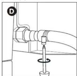
natural_image
Technical diagram of a pipe connection with a screwdriver and a circular motion indicator (no text or symbols)6.3.2 K OPPELING B
natural_image
Pure mechanical diagram showing a pipe joint with a bolt and arrow, no text or symbols present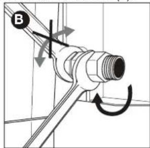
text_image
Bnatural_image
Technical diagram of a mechanical assembly with two connected components, one showing a threaded connector and the other a flanged nut (no text or symbols present)
text_image
Diagram showing pipe connection with directional arrows and a labeled point D, likely illustrating a mechanical or fluid system.natural_image
Mechanical assembly diagram showing a lever and belt mechanism (no text or symbols)natural_image
Technical line drawing of a mechanical assembly with no visible text or symbols
natural_image
Line drawing of a mechanical device with a circular component and a rectangular housing (no text or symbols)6.5 De gasfles ve vangen
natural_image
Line drawing of a toothbrush applying makeup with a round base (no text or symbols)7.5 Controleren op gaslekken
text_image
Diagram illustrating correct and incorrect hand positioning for a tool, with checkmark and cross symbols indicating precision and error.natural_image
Two technical diagrams showing a gas cylinder and a connector with a label (no text or symbols present)
text_image
C barbe D barbecook
natural_image
Technical line drawing of a mechanical component with a shaft and pin assembly (no text or symbols)
natural_image
Simple line drawing of a string with two circular ends and a dot at the end (no text or symbols)natural_image
Technical line drawing of a mechanical device with a lever and adjustment knob (no text or symbols)natural_image
Diagram of a fish-shaped object with internal structures and no visible text or symbols
natural_image
Technical line drawing of a mechanical assembly with internal components and directional arrows (no text or symbols)natural_image
Technical line drawing of a mechanical part with an arrow indicating direction (no text or symbols)text_image
Technical diagram showing fire extinguisher and gas cylinder with labeled dimensions H, D, and a cross symbol indicating failure or failure.
natural_image
Technical diagram of a mechanical assembly with a pipe fitting and directional arrow (no text or symbols)
natural_image
Technical diagram of a mechanical assembly with a screwdriver and pipe connection (no text or labels)6.3.2 M ANCHON B
natural_image
Technical diagram of a mechanical connector with threaded shaft and hexagonal connectors, showing directional arrow (no text or symbols)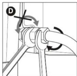
text_image
Technical diagram showing pipe connection with directional arrows and a labeled point Dnatural_image
Technical line drawing of a mechanical device with a spring and adjustment knob (no text or symbols)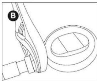
natural_image
Technical line drawing of a mechanical component with a circular housing and a curved arm (no text or symbols)natural_image
Technical line drawing of a mechanical assembly with no visible text or symbols
natural_image
Line drawing of a mechanical device with no visible text or symbols
natural_image
Line drawing of a barbecue stick with label 'barbecue' on the head (no other text or symbols)7.5 Vérifier l'étanchéi é au gaz
natural_image
Simple line drawing of a hand holding a tool or device with a circular indicator (no text or symbols)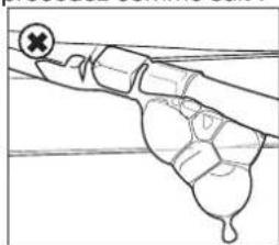
natural_image
Diagram of a hand holding a small object with a cross mark, no text or symbols presentnatural_image
Simple line drawing of a gas cylinder with two arrows indicating flow direction (no text or symbols)
text_image
barbara B
text_image
C Batter
text_image
D ! barbecook
natural_image
Technical line drawing of a mechanical tool with a shaft and base, showing no text or symbols
natural_image
Simple line drawing of a lever with two circular ends and a fulcrum (no text or symbols)natural_image
Technical line drawing of a mechanical device with a downward arrow indicating motion or force (no text or symbols present)natural_image
Diagram of a fish-shaped object with internal structures and no visible text or symbols
natural_image
Technical line drawing of a mechanical assembly with no visible text or symbolsnatural_image
Technical line drawing of a mechanical component with an arrow indicating upward motion (no text or symbols)text_image
Technical diagram showing a gas cylinder with height H and diameter D, alongside a cross symbol on a table.
text_image
Technical diagram showing two mechanical assembly steps labeled A and B, with arrows indicating movement or force direction.text_image
Technical diagram showing two mechanical assembly steps labeled C and D, with arrows indicating direction of movement.6.3.2 A NSCHLUSS B
text_image
Technical diagram showing pipe connection and valve assembly with labeled components C and Dnatural_image
Diagram of a mechanical measuring tool with a hook and ring, no text or symbols present
natural_image
Mechanical assembly diagram showing a lever and belt mechanism (no text or symbols)natural_image
Technical line drawing of a mechanical assembly with no visible text or symbols
natural_image
Technical line drawing of a mechanical device with no visible text or symbols
natural_image
Line drawing of a decorative lamp with 'barbecook' text on the lid (no other text or symbols)natural_image
Pure mechanical diagram showing a lever and fulcrum with no text or symbols
natural_image
Diagram of a hand holding a tool or device with a cross mark, no text or symbols presentnatural_image
Line drawing of a gas cylinder with labeled components and directional arrows (no text or symbols)
text_image
B barbecock
text_image
barbe C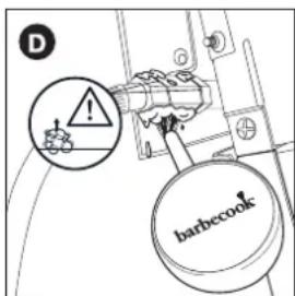
text_image
D ! barbecook
natural_image
Technical line drawing of a mechanical tool with a shaft and connector (no text or symbols)
natural_image
Simple line drawing of a lever with two circular ends and a central dot (no text or symbols)natural_image
Diagram of a mechanical device interior with arrows indicating motion or force direction (no text or symbols)natural_image
Diagram of a cylindrical object with internal structural elements and no visible text or symbols
natural_image
Technical line drawing of a mechanical assembly with no visible text or symbolsnatural_image
Technical line drawing of a mechanical component with an arrow indicating upward motion (no text or symbols)text_image
Technical diagram showing fire extinguisher and gas stove with labeled dimensions H, D, and no warning symboltext_image
heatbox heatbox6.3.1 A COPLAMIENTO A
natural_image
Technical diagram of a mechanical component with a directional arrow indicating movement (no text or symbols present)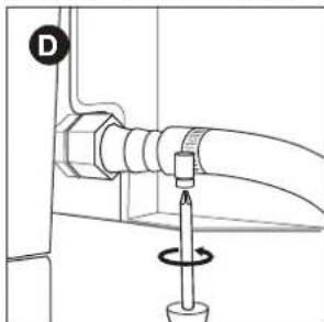
natural_image
Technical diagram of a mechanical assembly with a screwdriver and rotating component (no text or symbols)6.3.2 A COPLAMIENTO B
natural_image
Technical diagram of a mechanical connector with threaded and flanged parts, showing directional arrow (no text or symbols)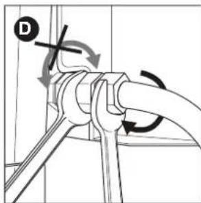
text_image
Technical diagram showing pipe connection with directional arrows and label D, likely illustrating a mechanical or fluid system.6.4 Conectar la manguera y la bombona
natural_image
Technical line drawing of a mechanical assembly with a tool and curved components (no text or symbols)
natural_image
Technical line drawing of a mechanical component with a circular housing and a bracket (no text or symbols)natural_image
Technical line drawing of a mechanical assembly with no visible text or symbols
natural_image
Line drawing of a mechanical device with a valve and housing (no text or symbols)
natural_image
Line drawing of a bathtub with a handle and label (no text or symbols on the object itself)7.5 Para comprobar si hay fugas de gas
natural_image
Line drawing of a mechanical component with a circular dial indicator (no text or symbols)
natural_image
Simple line drawing of a hand gripping a tool or device (no text or symbols)natural_image
Line drawing of a gas cylinder with directional arrows indicating flow or movement (no text or symbols)
text_image
B Inbetecole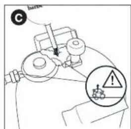
text_image
C Batter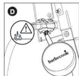
text_image
D ! barbecook
natural_image
Technical line drawing of a mechanical tool with a shaft and connector (no text or symbols)
natural_image
Simple line drawing of a string with two circular ends and a dot at the end (no text or symbols)natural_image
Technical line drawing of a mechanical component with a directional arrow indicating motion (no text or symbols)
natural_image
Diagram of a fish-shaped object with internal structures and no visible text or symbols
natural_image
Technical line drawing of a mechanical assembly with internal components and directional arrows (no text or symbols)natural_image
Technical line drawing of a mechanical component with an arrow indicating upward motion (no text or symbols)text_image
Technical diagram showing a gas cylinder with height H and diameter D, alongside a mechanical device with cross symbol and warning symbol.
text_image
barbecock6.3.1 R ACCORDO A
natural_image
Diagram of a mechanical or electrical component with a pipe fitting and directional arrow (no text or symbols)
natural_image
Technical diagram of a pipe connection with a screwdriver and rotating knob (no text or symbols)6.3.2 R ACCORDO B
natural_image
Technical diagram of a mechanical connector with threaded shaft and bolted joint (no text or symbols)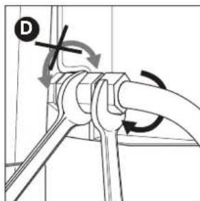
text_image
Technical diagram showing pipe connection with directional arrows and a labeled point Dnatural_image
Technical line drawing of a mechanical component with a circular housing and a curved arm (no text or symbols)natural_image
Technical line drawing of a mechanical assembly with no visible text or symbols
natural_image
Line drawing of a mechanical device with no visible text or symbols
natural_image
Line drawing of a toothpaste brush with 'barbecock' branding on the lid (no additional text or symbols)natural_image
Pure technical line drawing of a mechanical component without any text, numbers, or symbols
natural_image
Diagram of a hand holding a tool with a cross mark, no text or symbols presentnatural_image
Line drawing of a gas cylinder with a side cover and two arrows pointing to its side (no text or symbols)
text_image
B barbecue
text_image
barle C
text_image
D barbecook
natural_image
Technical line drawing of a mechanical tool with a shaft and connector (no text or symbols)
9 ACCENSIONE DEI FORNELLI

natural_image
Simple line drawing of a lever with two circular ends and a fulcrum (no text or symbols)natural_image
Technical line drawing of a mechanical assembly with a lever and directional arrow (no text or symbols)natural_image
Diagram of a fish-shaped boat with marked parts and no visible text or symbols
natural_image
Technical line drawing of a mechanical assembly with internal components and directional arrows (no text or symbols)natural_image
Technical line drawing of a mechanical component with an arrow indicating upward motion (no text or symbols)text_image
barbecool²natural_image
Diagram of a mechanical joint or bracket with a bolt and nut, showing an arrow pointing to a specific component (no text or symbols present)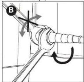
text_image
Bnatural_image
Technical diagram of a mechanical assembly with a pipe fitting and directional arrow (no text or labels)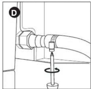
natural_image
Technical diagram of a mechanical assembly with a valve and rotating knob (no text or symbols)natural_image
Technical diagram showing a mechanical joint with a bolt and directional arrow (no text or symbols)
text_image
Bnatural_image
Technical diagram of a mechanical joint with a threaded connector and directional arrow (no text or symbols)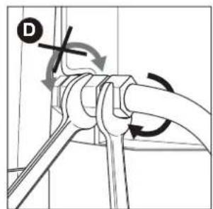
text_image
Technical diagram showing pipe connection with directional arrows and a labeled point Dnatural_image
Technical line drawing of a mechanical component with a circular housing and a curved arm (no text or symbols)natural_image
Technical line drawing of a mechanical assembly with no visible text or symbols
natural_image
Line drawing of a mechanical device with no visible text or symbols
natural_image
Line drawing of a toothpaste brush with 'barbecook' label (no additional text or symbols)natural_image
Simple line drawing of a mechanical component with a circular end and a checkmark (no text or symbols)
natural_image
Simple line drawing of a hand holding a tool or device with a cross mark, no text or symbols present.natural_image
Line drawing of a gas cylinder with two arrows indicating flow direction (no text or symbols)
text_image
barbecue B
text_image
C barle !
text_image
D barbecook
natural_image
Technical line drawing of a mechanical tool with a lever and shaft, showing no text or symbols
natural_image
Simple line drawing of a lever with two circular ends and a fulcrum (no text or symbols)natural_image
Technical line drawing of a mechanical device with a lever and cooling mechanism (no text or symbols)9.5 Verificar as chamas
natural_image
Diagram of a fish-shaped boat with visible hull, hull, and side profile (no text or labels)
natural_image
Technical line drawing of a mechanical assembly with no visible text or symbolstext_image
QR code image containing encoded data, with a central logo or watermarkGO TO WWW.BARBECOOK.COM, REGISTER YOUR BARBECOOK AND YOUR BARBECOOK EXPERIENCE WILL BE FURTHER IMPROVED!
THIS IS YOUR UNIQUE SERIAL N°
4.1 Venturirör
natural_image
Technical line drawing of a mechanical part with an arrow indicating direction (no text or symbols)text_image
Technical diagram showing a fire extinguisher and its corresponding safety symbol with cross mark
natural_image
Pure mechanical diagram showing a pipe connection with an arrow indicating direction (no text or symbols)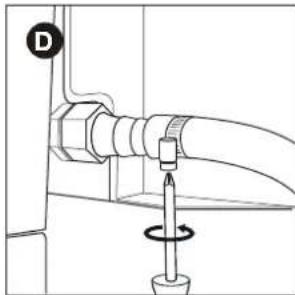
natural_image
Technical diagram of a mechanical assembly with a screw and rotating shaft (no text or symbols)6.3.2 KOPPLING B
natural_image
Technical diagram showing a mechanical joint with a bolt and arrow indicating direction (no text or symbols)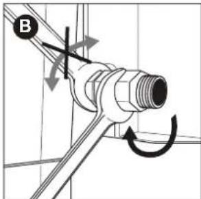
text_image
Bnatural_image
Technical diagram of a mechanical joint or connector with a threaded connector and a separate bolt, showing no text or symbols.
text_image
Technical diagram showing pipe connection with directional arrows and label D, likely illustrating a mechanical or fluid system.natural_image
Line drawing of a mechanical measuring tool with a pipette and scale, no text or symbols present
natural_image
Technical line drawing of a mechanical assembly with a circular component and a labeled component (B), no text or symbols present.natural_image
Technical line drawing of a mechanical assembly with no visible text or symbols
natural_image
Line drawing of a mechanical device with no visible text or symbols
natural_image
Line drawing of a toothbrush with 'barbecook' label on the head (no other text or symbols)natural_image
Pure technical line drawing of a pipe fitting with a circular gauge (no text or symbols)
natural_image
Diagram of a hand holding a tool or device with a cross mark, no text or symbols presentnatural_image
Line drawing of a gas cylinder with two arrows pointing to its side (no text or symbols)
text_image
B Inbetecock
text_image
barbe C
text_image
D barbecook
natural_image
Technical line drawing of a mechanical tool with a shaft and connector (no text or symbols)
natural_image
Simple line drawing of a lever with two circular ends and a fulcrum (no text or symbols)natural_image
Technical diagram of a mechanical assembly with a lever and directional arrow (no text or symbols)natural_image
Diagram of a fish-shaped structure with internal web-like patterns and no visible text or symbols
natural_image
Technical line drawing of a mechanical assembly with no visible text or symbolsnatural_image
Technical line drawing of a mechanical component with an arrow indicating upward motion (no text or symbols)text_image
Technical diagram showing fire extinguisher and equipment with labeled dimensions H, D, and a cross symbol indicating failure or hazard.
| Land | Sammenkobling |
| BE, CH, CZ, DK, ES, FI, GB, IE, IT, PT, SI | Sammenkobling A |
| FR | Sammenkobling B |

text_image
beefecock6.3.1 S AMMENKOBLING A
text_image
Technical diagram showing two mechanical assembly steps labeled A and B, with arrows indicating movement or force direction.text_image
Technical diagram showing two mechanical assembly steps labeled C and D, with arrows indicating direction of movement.6.3.2 S AMMENKOBLING B
text_image
Technical diagram showing pipe connection and valve assembly with labeled components A and Btext_image
Technical diagram showing pipe connection and valve mechanism with labeled components C and Dnatural_image
Technical line drawing of a mechanical assembly with a circular component and a bracket (no text or symbols)natural_image
Technical line drawing of a mechanical assembly with no visible text or symbols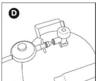
natural_image
Line drawing of a mechanical device with a circular component and a rectangular housing (no text or symbols)
Brug kun regulatorer, der er i overensstemmelse med EN 16129.
natural_image
Line drawing of a toothpaste brush with 'barbecook' label (no additional text or symbols)natural_image
Pure technical diagram of a pipe joint with a checkmark indicating a detail (no text or symbols)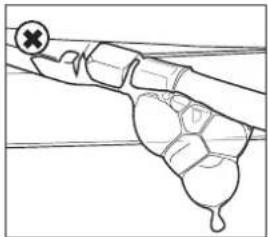
natural_image
Diagram of a mechanical or electrical component with no visible text or symbolsnatural_image
Line drawing of a gas cylinder with internal bands and a labeled section A (no text or symbols on the diagram itself)
text_image
harbiscock B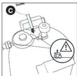
text_image
C hane
text_image
D barbecook
Din trykregulator og sammenkobling kan afvige fra de viste i illustrationen.
natural_image
Technical line drawing of a mechanical component with an arrow indicating direction (no text or symbols)
natural_image
Simple line drawing of a string with two circular ends and a dot at the end (no text or symbols)9.2.2 B RUG AF EN TÆNDSTIK
natural_image
Technical line drawing of a server rack with a directional arrow indicating movement (no text or symbols present)natural_image
Diagram of a boat hull with marked sections and internal structures (no text or symbols)
natural_image
Technical line drawing of a mechanical assembly with internal components and directional arrows (no text or symbols)natural_image
Technical line drawing of a mechanical component with an arrow indicating upward motion (no text or symbols)text_image
Technical diagram showing a gas cylinder with height H and diameter D, alongside a cross symbol indicating failure or absence.
natural_image
Pure mechanical diagram showing a pipe fitting with a circular component and an arrow indicating direction (no text or symbols)
natural_image
Technical diagram of a mechanical assembly with a screw and rotating knob (no text or symbols)6.3.2 L IITIN B
natural_image
Technical diagram of a mechanical connector with threaded pipe and bolted joint (no text or symbols)
text_image
Diagram showing pipe connection with directional arrows and a cross symbol, labeled with letter Dnatural_image
Technical line drawing of a mechanical assembly with a circular component and a labeled component B (no text or symbols present)natural_image
Technical line drawing of a mechanical assembly with no visible text or symbols
natural_image
Line drawing of a mechanical device with a valve and housing (no text or symbols)
natural_image
Line drawing of a bamboo-cook brush with a wooden handle and label (no text or symbols on the object itself)natural_image
Pure mechanical diagram showing a lever mechanism with a circular dial indicator (no text or symbols)
natural_image
Simple line drawing of a mechanical component or tool with a cross mark and a droplet, no text or symbols present.natural_image
Line drawing of a gas cylinder with two arrows indicating flow direction (no text or symbols)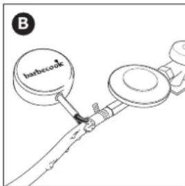
text_image
B Inbecook
text_image
barble C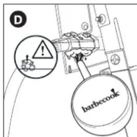
text_image
D !! barbecook
natural_image
Technical line drawing of a mechanical component with a lever and shaft, showing no text or symbols
natural_image
Simple line drawing of a string with two circular ends and a dot at the end (no text or symbols)natural_image
Technical line drawing of a server rack with a directional arrow indicating rotation (no text or symbols)natural_image
Diagram of a fish-shaped object with internal structures and dashed lines indicating flow or positioning (no text or symbols)
natural_image
Technical line drawing of a mechanical assembly with internal components and directional arrows (no text or symbols)natural_image
Technical line drawing of a mechanical component with an arrow indicating upward motion (no text or symbols)6 TILKOBLING AV GASS TIL APPARATET
6.1 Hvilken flas e, slange, regulator
text_image
Technical diagram showing a gas cylinder with height H and diameter D, alongside a mechanical device with no visible text or symbols.text_image
beefecool6.3.1 K OBLING A
Du trenger en 19 mm fastnøkkel og en stjemeskrutrekker.
- Skru koblingen på gasslangen av apparatet (A) og skru det fast med en 19 mm fastnøkkel (B).
text_image
A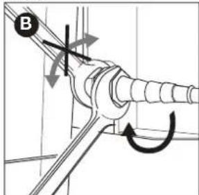
text_image
Bnatural_image
Technical diagram of a mechanical assembly with a labeled component (C) and directional arrow, no readable text or symbols present.
natural_image
Technical diagram of a mechanical assembly with a screw and rotating shaft (no text or symbols)6.3.2 K OBLING B
natural_image
Technical diagram of a mechanical assembly with a threaded connector and hexagonal connectors (no text or symbols)
text_image
Technical diagram showing pipe connection with directional arrows and a labeled component 'D'natural_image
Technical line drawing of a mechanical measuring tool with a pipette and scale (no text or symbols)
natural_image
Technical line drawing of a mechanical component with a circular housing and a labeled part B (no text or symbols present)-
Koble trykkregulatoren til gassflas en. Gjør ett av følgende:
-
Dersom regulatoren har en mutter, skru regulatoren med urviseren på flas en og stram til mutteren med en skiftenøkkel (C).
- Hvis regulatoren har skruegjenge, skrue regulatoren mot urviseren på gassflas en (D).

natural_image
Technical line drawing of a mechanical assembly with no visible text or symbols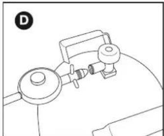
natural_image
Line drawing of a mechanical device with no visible text or symbols
Bruk kun regulatorer som er i samsvar med EN 16129.
6.5 Skifte flas en
7 SJEKKING FOR GASSLEKKASJE
natural_image
Line drawing of a makeup brush with 'barbecook' text on the head (no other text or symbols)natural_image
Pure mechanical diagram showing a pipe joint with a circular valve and a checkmark (no text or symbols)
natural_image
Diagram of a mechanical or electrical component with no visible text, numbers, or symbolsnatural_image
Line drawing of a gas cylinder with a labeled cap and two arrows indicating direction (no text or symbols)
text_image
barbecue B
text_image
barbe C
text_image
D barbecook
natural_image
Technical line drawing of a mechanical tool with a shaft and base, showing a directional arrow (no text or symbols)natural_image
Simple line drawing of a string with two circular ends and a dot at the end (no text or symbols)natural_image
Technical line drawing of a mechanical assembly with no visible text or symbols11 VEDLIKEHOLD AV APPARATET
natural_image
Diagram of a fish-shaped object with internal structures and dashed lines, no text or symbols present
natural_image
Technical line drawing of a mechanical assembly with internal components and directional arrows (no text or symbols)natural_image
Technical line drawing of a mechanical component with an arrow indicating upward motion (no text or symbols)text_image
Technical diagram showing a gas cylinder with height H and diameter D, alongside a cross symbol indicating no protection or hazard.
text_image
beebecock6.3.1 A CSATLAKOZÓ
natural_image
Technical diagram of a mechanical assembly with a pipe fitting and directional arrow (no text or symbols)
natural_image
Technical diagram of a mechanical assembly with a valve and rotating knob (no text or symbols)6.3.2 B CSATLAKOZÓ
natural_image
Diagram of a mechanical joint or bracket with an arrow indicating direction (no text or symbols present)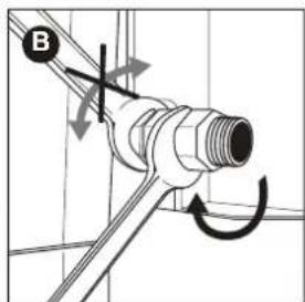
text_image
Bnatural_image
Technical diagram of a mechanical joint with a threaded connector and a bolted joint, showing directional arrow (no text or symbols)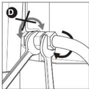
text_image
Technical diagram showing pipe connection with directional arrows and a labeled component 'D'natural_image
Technical line drawing of a micrometer measuring a cylindrical object with a pointer (no text or symbols)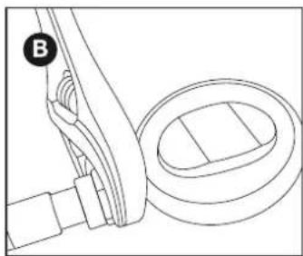
natural_image
Technical line drawing of a mechanical assembly with a circular component and a bracket (no text or symbols)natural_image
Technical line drawing of a mechanical assembly with no visible text or symbols
natural_image
Line drawing of a mechanical device with no visible text or symbols
natural_image
Line drawing of a toothbrush with 'barbecook' text on its body (no other text or symbols)natural_image
Pure mechanical diagram showing a lever and pivot point without any text or symbols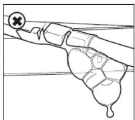
natural_image
Simple line drawing of a hand holding a tool or device, with no visible text or symbols.natural_image
Line drawing of a gas cylinder with two arrows indicating direction (no text or symbols)
text_image
barbecue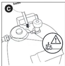
text_image
C barix !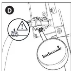
text_image
D barbecook
natural_image
Technical line drawing of a mechanical tool with a shaft and connector (no text or symbols)
natural_image
Simple line drawing of a lever with two circular ends and a central dot (no text or symbols)natural_image
Technical line drawing of a mechanical device with a lever and adjustment arrow (no text or symbols)natural_image
Diagram of a fish-shaped object with internal structures and no visible text or symbols
natural_image
Technical line drawing of a mechanical assembly with internal components and directional arrows (no text or symbols)natural_image
Technical line drawing of a mechanical component with an arrow indicating direction (no text or symbols)text_image
Technical diagram showing a gas cylinder with height H and diameter D, alongside a mechanical device with cross symbol and warning label.
text_image
barbecool6.3.1 C UPLAJUL A
natural_image
Technical diagram of a mechanical assembly with a pipe fitting and directional arrow (no text or symbols)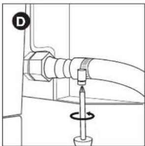
natural_image
Technical diagram of a pipe connection with a screwdriver and a circular motion indicator (no text or symbols)6.3.2 C UPLAJUL B
natural_image
Diagram of a mechanical joint or bracket with an arrow indicating direction (no text or symbols present)
text_image
Bnatural_image
Technical diagram of a mechanical assembly with two connectors and a valve (no text or symbols)
text_image
Technical diagram showing pipe connection with directional arrows and a labeled component 'D'natural_image
Technical line drawing of a mechanical measuring tool with a pipette and scale (no text or symbols)
natural_image
Technical line drawing of a mechanical assembly with a circular component and a bracket (no text or symbols)natural_image
Technical line drawing of a mechanical assembly with no visible text or symbols
natural_image
Line drawing of a mechanical device with a knob and handle (no text or symbols)
natural_image
Line drawing of a toothpaste brush with 'barbecook' branding on the head (no additional text or symbols)natural_image
Pure technical diagram of a pipe joint with a circular gauge (no text or symbols)
natural_image
Simple line drawing of a hand gripping a tool or device (no text or symbols)natural_image
Line drawing of a gas cylinder with directional arrows indicating flow or movement (no text or symbols)
text_image
B barbecue®
text_image
barnes C
text_image
D ! barbecook
natural_image
Technical line drawing of a mechanical tool with a shaft and connector (no text or symbols)
natural_image
Simple line drawing of a string with two circular ends and a dot at the end (no text or symbols)natural_image
Diagram of a mechanical device interior with arrows indicating motion or force direction (no text or symbols)natural_image
Diagram of a fish-shaped object with internal structures and no visible text or symbols
natural_image
Technical line drawing of a mechanical assembly with internal components and directional arrows (no text or symbols)natural_image
Technical line drawing of a mechanical component with an arrow indicating direction (no text or symbols)text_image
heatbecool®6.3.1 S POJKA A
natural_image
Diagram of a door joint with a bolt and nut, showing an arrow indicating direction (no text or symbols)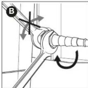
text_image
Bnatural_image
Technical diagram of a mechanical assembly with a pipe fitting and directional arrow (no text or labels)
natural_image
Technical diagram of a mechanical assembly with a screw and rotating component (no text or symbols)6.3.2 S POJKA B
natural_image
Diagram of a mechanical joint or connector with an arrow indicating direction (no text or symbols present)
text_image
Bnatural_image
Technical diagram of a mechanical connector with threaded and flanged parts, no visible text or symbols
text_image
Technical diagram showing pipe connection with directional arrows and a labeled component 'D'natural_image
Technical line drawing of a mechanical assembly with a circular component and a labeled component (B), no text or symbols present.natural_image
Technical line drawing of a mechanical assembly with no visible text or symbols
natural_image
Line drawing of a mechanical device with a knob and lever (no text or symbols)
natural_image
Line drawing of a toothpaste brush with 'barbecook' label on the head (no other text or symbols)natural_image
Pure technical line drawing of a pipe fitting with a checkmark indicating a detail (no text or symbols)
natural_image
Line drawing of a hand holding a tool with a cross mark and droplet shape, no text or symbols presentnatural_image
Line drawing of a gas cylinder with two arrows indicating flow direction (no text or symbols)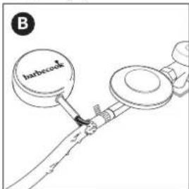
text_image
Barbecook B
text_image
C barble !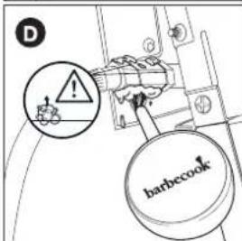
text_image
D barbecook
natural_image
Technical line drawing of a mechanical tool with a shaft and connector (no text or symbols)
natural_image
Simple line drawing of a string with two circular ends and a dot at the end (no text or symbols)natural_image
Technical line drawing of a mechanical device with a lever and adjustment arrow (no text or symbols)natural_image
Diagram of a fish-shaped object with internal structures and no visible text or symbols
natural_image
Technical line drawing of a mechanical assembly with internal components and directional arrows (no text or symbols)natural_image
Technical line drawing of a cylindrical mechanical part with an arrow indicating direction (no text or symbols)text_image
Technical diagram showing a gas cylinder with height H and diameter D, alongside a cross-sectional view of a mechanical device with no visible text or symbols.
text_image
barbecock6.3.1 Σ' YZEYEH A
natural_image
Technical diagram of a mechanical assembly with a pipe fitting and directional arrow (no text or symbols)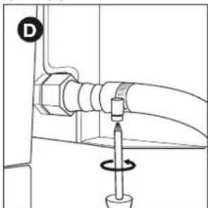
natural_image
Technical diagram of a mechanical assembly with a bolt and rotating component (no text or symbols)6.3.2 Σ' YZEYEH B
natural_image
Diagram of a mechanical joint or bracket with an arrow indicating direction (no text or symbols present)
text_image
Bnatural_image
Technical diagram of a mechanical connector with threaded and hexagonal parts, showing directional arrow (no text or symbols)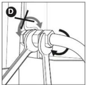
text_image
Technical diagram showing pipe connection with directional arrows and a labeled component 'D'natural_image
Technical line drawing of a mechanical assembly with a curved component and a circular housing (no text or symbols)natural_image
Technical line drawing of a mechanical assembly with no visible text or symbols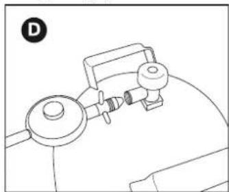
natural_image
Line drawing of a mechanical device with a knob and lever (no text or symbols)
natural_image
Line drawing of a toothbrush with 'barbecook' label on the head (no other text or symbols)text_image
Technical diagram showing a pipe connection with a checkmark indicating approval or status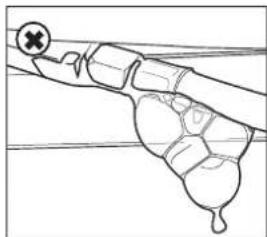
natural_image
Diagram of a hand gripping a tool or device with a cross symbol on the handle (no text or labels present)natural_image
Line drawing of a gas cylinder with two arrows pointing to its side (no text or symbols)
text_image
B barbecue
text_image
barbe C
text_image
D barbecook
natural_image
Technical line drawing of a mechanical tool with a shaft and connector (no text or symbols)
natural_image
Simple line drawing of a lever with two circular ends and a fulcrum (no text or symbols)natural_image
Technical line drawing of a mechanical device with a lever and adjustment arrow (no text or symbols)natural_image
Diagram of a fish-shaped structure with internal components and no visible text or symbols
natural_image
Technical line drawing of a mechanical assembly with no visible text or symbols3 DÔLEŽITÉ BEZPEČNOSTNÉ POKYNY
3.1 Prečítajte si a dodržiavajte pokyny
natural_image
Technical line drawing of a mechanical component with an arrow indicating direction (no text or symbols)text_image
Technical diagram showing gas cylinder and valve assembly with labeled dimensions H, D, and a cross symbol indicating failure or failure.
natural_image
Diagram of a door with a bolt and nut, showing a left angle indicator (no text or symbols)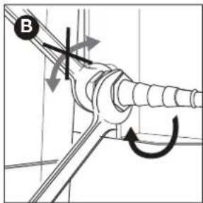
text_image
B- Nasuňte hadicu na spojku (C) a dotiahnite eskapásku pomocou krížového skrutkovača (D).

natural_image
Technical diagram of a mechanical assembly with a pipe fitting and directional arrow (no text or labels)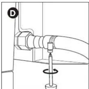
natural_image
Technical diagram of a mechanical assembly with a screw and rotating component (no text or symbols)6.3.2 S POJKA TYPU B
natural_image
Diagram of a mechanical joint or bracket with an arrow indicating direction (no text or symbols present)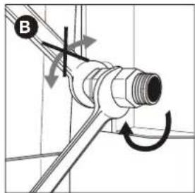
text_image
Bnatural_image
Technical diagram of a mechanical joint with two connectors and a directional arrow (no text or symbols)
text_image
Technical diagram showing pipe connection with directional arrows and a labeled component 'D'natural_image
Technical line drawing of a mechanical measuring tool with a pipette and scale (no text or symbols)
natural_image
Mechanical assembly diagram showing a linkage mechanism with a circular component and a labeled part B (no text or symbols present)natural_image
Technical line drawing of a mechanical assembly with no visible text or symbols
natural_image
Line drawing of a mechanical device with a circular component and lever (no text or symbols)
natural_image
Line drawing of a bamboo-cook gong with a wooden stick (no text or symbols)7.5 Kontrola úniku plynu
natural_image
Pure mechanical diagram showing a lever and pivot point without any text or symbols
natural_image
Diagram of a mechanical or electrical component with no visible text, numbers, or symbolsnatural_image
Line drawing of a gas cylinder with two arrows indicating flow direction (no text or symbols)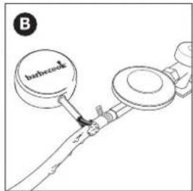
text_image
B barbecock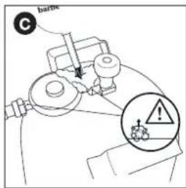
text_image
C barite !
text_image
D barbecook
natural_image
Technical line drawing of a mechanical tool with a shaft and base, showing a directional arrow (no text or symbols)
natural_image
Simple line drawing of a string with two circular ends and a dot at the end (no text or symbols)natural_image
Technical line drawing of a mechanical device with a lever and adjustment arrow (no text or symbols)text_image
QR code image containing encoded data, with a central logo or watermarkGO TO WWW.BARBECOOK.COM, REGISTER YOUR BARBECOOK AND YOUR BARBECOOK EXPERIENCE WILL BE FURTHER IMPROVED!
THIS IS YOUR UNIQUE SERIAL N°
10. UŽITOČNÉ TIPY
10.1 Predhrievanie grilu
natural_image
Diagram of a fish-shaped object with internal structures and no visible text or symbols
natural_image
Technical line drawing of a mechanical assembly with internal components and directional arrows (no text or symbols)3 Olulised ohutusjuhised 212
3 OLULISED OHUTUSJUHISED
natural_image
Technical line drawing of a mechanical component with an arrow indicating direction (no text or symbols)text_image
Technical diagram showing gas cylinder and container with labeled dimensions H, D, and a cross symbol indicating failure or failure.
text_image
heatbecool®6.3.1 M UHV A
natural_image
Diagram of a door with a bolt and nut, showing a left angle indicator (no text or symbols)
text_image
Bnatural_image
Technical diagram of a mechanical assembly with a pipe fitting and directional arrow (no text or labels)
natural_image
Technical diagram of a mechanical assembly with a screw and rotating component (no text or symbols)6.3.2 M UHV B
natural_image
Diagram of a mechanical joint or bracket with an arrow indicating direction (no text or symbols present)
text_image
Bnatural_image
Technical diagram of a mechanical assembly with a threaded connector and bolted joint (no text or symbols)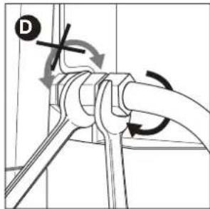
text_image
Technical diagram showing pipe connection with directional arrows and a labeled component 'D'natural_image
Technical illustration of a micrometer measuring a cylindrical object (no text or symbols present)
natural_image
Technical line drawing of a mechanical assembly with a circular component and a bracket (no text or symbols)natural_image
Technical line drawing of a mechanical assembly with no visible text or symbols
natural_image
Line drawing of a medical or laboratory setup with a device and tubing (no text or symbols)
natural_image
Line drawing of a bamboo-cook with a wooden stick and label (no text or symbols on the object itself)7.5 Gaasilekete kontrollimiseks
natural_image
Pure mechanical diagram showing a lever and pivot point without any text or symbols
natural_image
Diagram of a mechanical or biological structure with no visible text, numbers, or symbolsnatural_image
Line drawing of a gas cylinder with two arrows indicating direction (no text or symbols)
text_image
B barbecock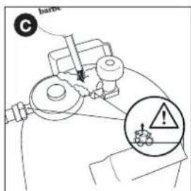
text_image
C barbe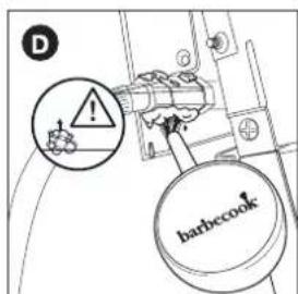
text_image
D barbecook
natural_image
Technical line drawing of a mechanical component with a shaft and housing, showing a directional arrow (no text or symbols)
natural_image
Simple line drawing of a string with two circular ends and a dot at the end (no text or symbols)natural_image
Diagram of a mechanical device interior with arrows indicating motion or force direction (no text or symbols)natural_image
Diagram of a fish-shaped object with internal structures and no visible text or symbols
natural_image
Technical line drawing of a mechanical assembly with internal components and directional arrows (no text or symbols)natural_image
Technical line drawing of a cylindrical electronic component with an arrow indicating upward motion (no text or symbols)text_image
Technical diagram showing gas cylinder and container with labeled dimensions H, D, and a cross symbol indicating failure or failure.
natural_image
Diagram of a door with a bolt and nut, showing a left-side arrow pointing to a screw (no text or symbols present)
text_image
Bnatural_image
Technical line drawing of a mechanical assembly with a pipe fitting and directional arrow (no text or symbols)
natural_image
Technical diagram of a mechanical assembly with a screw and rotating component (no text or symbols)6.3.2 B MOVA
natural_image
Diagram of a mechanical joint or bracket with an arrow indicating direction (no text or symbols present)
text_image
Bnatural_image
Technical diagram of a mechanical joint with two connectors and a directional arrow (no text or symbols)
text_image
Technical diagram showing pipe connection with directional arrows and a labeled component 'D'natural_image
Technical line drawing of a micrometer measuring a cylindrical object (no text or symbols)
natural_image
Technical line drawing of a mechanical assembly with a circular component and a bracket (no text or symbols)natural_image
Technical line drawing of a mechanical assembly with no visible text or symbols
natural_image
Line drawing of a mechanical device with no visible text or symbols
natural_image
Line drawing of a bamboo-cook matchbox with a wooden handle (no text or symbols)natural_image
Line drawing of a mechanical joint or pipe with a circular mark and checkmark (no text or symbols)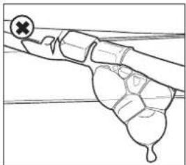
natural_image
Line drawing of a hand holding a tool with a cross mark and a droplet, no text or symbols presentnatural_image
Line drawing of a gas cylinder with two arrows indicating flow direction (no text or symbols)
text_image
B barbecok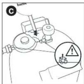
text_image
barbe C
text_image
D barbecook
natural_image
Technical line drawing of a mechanical tool with a shaft and connector (no text or symbols)
natural_image
Simple line drawing of a lever with two circular ends and a fulcrum (no text or symbols)natural_image
Technical line drawing of a mechanical device with a lever and adjustment arrow (no text or symbols)natural_image
Diagram of a fish-shaped object with internal structures and no visible text or symbols
natural_image
Technical line drawing of a mechanical assembly with no visible text or symbolsnatural_image
Technical line drawing of a cylindrical electronic component with an arrow indicating upward motion (no text or symbols)text_image
Technical diagram showing gas cylinder with nozzles and height dimension H, alongside a cross symbol inside a container labeled 3-Φ.
text_image
beefecool6.3.1 A SAVIENOJUMS
Nepieciešama 19 mm uzgriežnatslēga un krusta skrūvgriezis.
natural_image
Diagram of a door with a bolt and nut, showing a left angle indicator (no text or symbols)
text_image
Bnatural_image
Technical diagram of a mechanical assembly with a pipe fitting and directional arrow (no text or symbols)
natural_image
Technical diagram of a mechanical assembly with a screw and rotating component (no text or symbols)6.3.2 B SAVIENOJUMS
natural_image
Diagram of a mechanical joint or bracket with an arrow indicating direction (no text or symbols present)
text_image
Bnatural_image
Technical diagram of a mechanical component with threaded connectors and a directional arrow (no text or symbols)
text_image
Technical diagram showing pipe connection with directional arrows and a labeled component 'D'6.4 Šlūtenes un balona pievienošana regulatoram
natural_image
Technical line drawing of a micrometer measuring a cylindrical object (no text or symbols)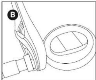
natural_image
Technical line drawing of a mechanical assembly with a circular component and a bracket (no text or symbols)natural_image
Technical line drawing of a mechanical assembly with no visible text or symbols
natural_image
Line drawing of a mechanical device with a cylindrical component and a base, no text or symbols present
Izmantojiet tikai regulatorus, kas atbilst EN 16129.
natural_image
Line drawing of a toothpaste brush with 'barbecook' branding on the head (no other text or symbols)natural_image
Pure technical line drawing of a pipe fitting with no text or symbols
natural_image
Simple line drawing of a hand holding a tool with a cross mark on the handle (no text or symbols)natural_image
Line drawing of a gas cylinder with labeled component A and directional arrows (no text or symbols on the diagram itself)
text_image
B barbecok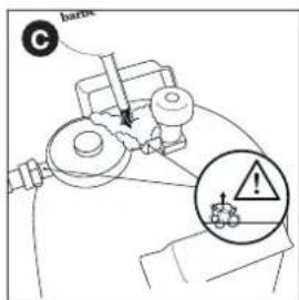
text_image
barbe C
text_image
D barbecook
natural_image
Technical line drawing of a mechanical tool with a shaft and connector (no text or symbols)
natural_image
Simple line drawing of a lever with two circular ends and a fulcrum (no text or symbols)natural_image
Diagram of a mechanical device interior with arrows indicating motion or force direction (no text or symbols)natural_image
Diagram of a fish-shaped container with internal structures and no visible text or symbols
natural_image
Technical line drawing of a mechanical assembly with internal components and directional arrows (no text or symbols)natural_image
Technical line drawing of a mechanical component with an arrow indicating direction (no text or symbols)text_image
Technical diagram showing gas cylinder and container with symbols and dimensions, including a no-smoking symbol and cross mark.
text_image
barbecool6.3.1 Z ŁACZKA A
natural_image
Diagram of a mechanical joint or bracket with a bolt and nut, showing an arrow indicating direction (no text or symbols present)
text_image
Bnatural_image
Technical diagram of a mechanical assembly with a pipe fitting and directional arrow (no text or symbols)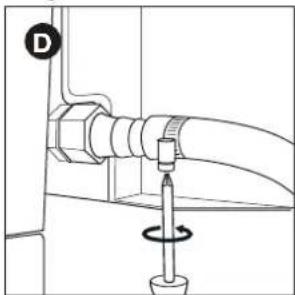
natural_image
Technical diagram of a mechanical assembly with a screw and rotating component (no text or symbols)6.3.2 Z ŁĄCZKA B
natural_image
Diagram of a mechanical joint or bracket with an arrow indicating direction (no text or symbols present)
text_image
Bnatural_image
Technical diagram of a mechanical component with threaded ports and a directional arrow (no text or symbols)
text_image
Technical diagram showing pipe connection with directional arrows and a labeled component 'D'natural_image
Technical line drawing of a micrometer measuring a cylindrical object (no text or symbols)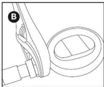
natural_image
Technical line drawing of a mechanical assembly with a circular component and a bracket (no text or symbols)natural_image
Technical line drawing of a mechanical assembly with no visible text or symbols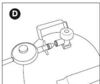
natural_image
Line drawing of a mechanical device with a circular base and cylindrical components (no text or symbols)
natural_image
Line drawing of a bamboo-cook drum with a wooden stick (no text or symbols)natural_image
Pure mechanical diagram showing a lever and fulcrum with no text or symbols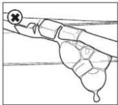
natural_image
Line drawing of a hand gripping a tool with a cross mark and a droplet on the grip (no text or symbols)natural_image
Line drawing of a gas cylinder with directional arrows indicating flow or movement (no text or symbols)
text_image
B Inbrecock
text_image
harm C
text_image
D barbecook
natural_image
Technical line drawing of a mechanical tool with a shaft and connector (no text or symbols)
natural_image
Simple line drawing of a string with two circular ends and a dot at the end (no text or symbols)natural_image
Technical line drawing of a mechanical component with arrows indicating motion or force (no text or symbols)natural_image
Diagram of a fish-shaped structure with internal structures and directional arrows (no text or labels)
natural_image
Technical line drawing of a mechanical assembly with internal components and directional arrows (no text or symbols)natural_image
Technical line drawing of a mechanical component with an arrow indicating direction (no text or symbols)text_image
Technical diagram showing a gas cylinder with height H and diameter D, alongside a cross symbol indicating failure or absence.
text_image
barbecool6.3.1 К уплунг А
natural_image
Diagram of a door with a bolt and nut, showing a left angle indicator (no text or symbols)
text_image
Bnatural_image
Technical diagram of a mechanical assembly with a pipe fitting and directional arrow (no text or labels)
natural_image
Technical diagram of a mechanical assembly with a screw and rotating component (no text or symbols)natural_image
Pure mechanical diagram showing a pipe fitting with an arrow indicating direction (no text or symbols)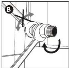
text_image
Bnatural_image
Technical diagram of a mechanical joint or connector with threaded and hexagonal parts, no visible text or symbols
text_image
Technical diagram showing pipe connection with directional arrows and a labeled component 'D'natural_image
Line drawing of a micrometer measuring the needle with a pipette (no text or symbols)
natural_image
Mechanical assembly diagram showing a lever and belt mechanism (no text or symbols)natural_image
Technical line drawing of a mechanical component with no visible text or symbols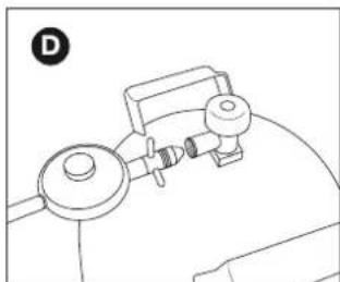
natural_image
Line drawing of a mechanical device with a lever and base mount (no text or symbols)
natural_image
Line drawing of a bamboo-cock with a wooden handle and textured body (no text or symbols)natural_image
Diagram of a hand holding a tool with a cross mark and a droplet, no text or symbols presentnatural_image
Line drawing of a gas cylinder with two arrows indicating direction (no text or symbols)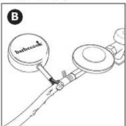
text_image
barbecue B
text_image
barble C
text_image
D ! barbecook
natural_image
Technical line drawing of a mechanical tool with a shaft and connector (no text or symbols)
natural_image
Simple line drawing of a lever with two circular ends and a fulcrum (no text or symbols)natural_image
Diagram of a mechanical device interior with arrows indicating motion or force direction (no text or symbols)natural_image
Technical line drawing of a mechanical assembly with internal components and directional arrows (no text or symbols)natural_image
Technical line drawing of a mechanical component with an arrow indicating direction (no text or symbols)6.1 Katero jeklenko, gibko cev in regulator?
Preden priklopite plin na napravo, morate kupiti plinsko jeklenko, cev in regulator tlaka. Spodnja tabela prikazuje, katero jeklenko, cev in regulator morate uporabiti.
V Belgiji (BE) mo ate na primer uporabiti propansko jeklenko s cevjo in regulatorjem za 37 mbar ali butansko jeklenko s cevjo in regulatorjem za 28–30 mbar.
| Država | Jeklenka, gibka cev in regulator |
| DK, GR, NO, SE, EE, LT, LV, CZ, PL, MT, HU, SI, SK, NL | Propan, 30 mbar/Butan, 30 mbar |
| ES, GB,, IE, PT, BE, FR, LU, IT, CY | Propan, 37 mbar/ Butan, 28 - 30 mbar |

text_image
Technical diagram showing a gas cylinder with height H and diameter D, alongside a mechanical device with cross symbol indicating failure or absence.
text_image
beebecock6.3.1 S POJKA A
natural_image
Diagram of a door with a bolt and nut, showing a left-pointing arrow (no text or symbols)
text_image
Bnatural_image
Technical diagram of a mechanical assembly with a pipe fitting and directional arrow (no text or labels)
natural_image
Technical diagram of a pipe connection with a screwdriver and a circular component (no text or symbols)6.3.2 S POJKA B
natural_image
Diagram of a mechanical joint or bracket with an arrow indicating direction (no text or symbols present)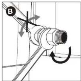
text_image
B- Gibko plinsko cev privij e na spojko (C) in jo zategnite z dvema ključema. Spojko držite z 22 mm ključem in medtem gibko cev privijaj e s francozom (D).

natural_image
Technical diagram of a mechanical assembly with a threaded connector and bolted joint (no text or symbols)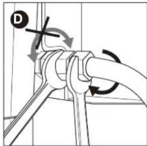
text_image
Technical diagram showing pipe connection with directional arrows and a labeled component 'D'6.4 Priključitev gibke cevi in jeklenke na regulator
natural_image
Line drawing of a micrometer measuring a curved gauge or dial, with no text or symbols present.
natural_image
Technical line drawing of a mechanical assembly with a circular component and a bracket (no text or symbols)-
Regulator tlaka priključite na plinsko jeklenko. Storite eno od naslednjega:
-
Če ima regulator matico, ga na jeklenko privij e v desno in matico zategnite s francozom (C).
- Če ima regulator vijačno glavo, ga na jeklen o privij e v levo (D).

natural_image
Technical line drawing of a mechanical assembly with no visible text or symbols
natural_image
Line drawing of a mechanical device with a cylindrical component and a rectangular housing (no text or symbols)
natural_image
Line drawing of a toothpaste brush with 'barbecook' branding on the head (no additional text or symbols)7.5 Kako preveriti uhajanje plina
natural_image
Pure mechanical diagram showing a lever and pivot point without any text, numbers, or symbols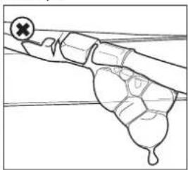
natural_image
Simple line drawing of a mechanical or biological structure with no visible text, numbers, or symbols.natural_image
Line drawing of a gas cylinder with two arrows indicating flow direction (no text or symbols)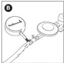
text_image
B barbecok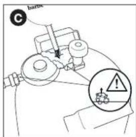
text_image
barbe C
text_image
D barbecook
natural_image
Technical line drawing of a mechanical tool with a shaft and connector (no text or symbols)
natural_image
Simple line drawing of a lever with two circular ends and a fulcrum (no text or symbols)natural_image
Technical line drawing of a mechanical device with a lever and directional arrow (no text or symbols)- Upravljalni gumb enega gorilnika nastavite na HIGH (Visoko).

natural_image
Diagram of a fish-shaped object with internal structures and dashed lines indicating sections (no text or symbols)
natural_image
Technical line drawing of a mechanical assembly with internal components and directional arrows (no text or symbols)natural_image
Technical line drawing of a mechanical part with an arrow indicating direction (no text or symbols)text_image
Technical diagram showing gas cylinder with nozzles and height dimension H, alongside a cross symbol inside a container labeled 3-Φ.
Roštilj je podešen za rad s butanskim/propanskim bocama od 4,5 do 15 kg s odgovarajućim niskotlačnim regulatorom. Preporučujemo da uređaj spojite na propan. Propan jamči kvalitetno izgaranje i manje je osjetljiv na smrzavanje. Visina (H) boce mora biti manja od 70 cm, bez obzira na širinu i promjer (D) boce.

Regulator tlaka i plinsku bocu kupite zajedno. Ne pristaju svi regulatori na sve boce.

Koristite isključivo crijevo za plin i egulator koji su homologirani za upotrebu u vašoj zemlji.
6.2 Sigurnosne upute
text_image
beebecool6.3.1 S POJKA A
Potreban Vam je ključ od 19 mm i križni odvijač.
natural_image
Diagram of a door with a bolt and nut, showing a left-pointing arrow (no text or symbols)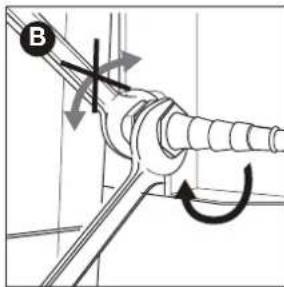
text_image
B- Nataknite crijevo na spojku (C) i pri egnite stezni prsten pomoću križnog odvijača (D)

natural_image
Technical diagram of a mechanical assembly with a labeled component (C) and an arrow indicating direction (no text or symbols present)
natural_image
Technical diagram of a pipe connection with a screwdriver and a circular component (no text or symbols)6.3.2 S POJKA B
Potreban Vam je ključ od 22 mm i podesivi ključ.
natural_image
Pure mechanical diagram showing a pipe fitting with an arrow indicating direction (no text or symbols)
text_image
Bnatural_image
Technical diagram of a mechanical assembly with two connectors and a valve (no text or symbols)
text_image
Technical diagram showing pipe connection with directional arrows and a labeled component 'D'natural_image
Technical line drawing of a micrometer measuring a cylindrical object with a pointer (no text or symbols)
natural_image
Technical line drawing of a mechanical assembly with a circular component and a labeled component (B), no text or symbols present.natural_image
Technical line drawing of a mechanical assembly with no visible text or symbols
natural_image
Line drawing of a mechanical device with no visible text or symbols
Koristite se samo regulatorima koji su sukladni s EN 16129.
6.5 Zamjena spremnika
- Zatvorite dovod plina i postavite sve kontrolne čvorove na OFF.
- Odspojite prazni spremnik i priključite puni spremnik.
- Provjerite spremnik, crijeva i sve plins e spojeve zbog curenja. Pogledajte "7 Provjera curenja plina".

Pozor, kada vršite zamjenu boce s plinom, to se mora obaviti dalje od svih izvora zapaljenja.
7 PROVJERA CURENJA PLINA
natural_image
Line drawing of a toothbrush with 'barbecook' label on the head (no other text or symbols)7.5 Kako biste provjerili curenje plina
natural_image
Two-step diagram showing a hand holding a tool and a close-up of the grip, with no visible text or symbols.Kako biste provjerili curenje plina postupite na sljedeći način:
natural_image
Line drawing of a gas cylinder with two arrows indicating direction (no text or symbols)
text_image
B barbecue
text_image
barbe C
text_image
D barbecook
Vaš regulator pritiska i spojka mogu biti drugačiji od onih prikazanih na slikama.
natural_image
Technical line drawing of a mechanical tool with a shaft and base, showing a directional arrow (no text or symbols)
natural_image
Simple line drawing of a lever with two circular ends and a fulcrum (no text or symbols)- Otvorite poklopac i postavite kontrolne čvorove glavnih plamenika na OFF.
- Ako nijedan plamenik još nije upaljen, otvor e dovod plina i pričekajte deset sekundi. Na taj način se plin stigne stabilizirati.
- Zapalite šibicu i držite je otprilike 13 mm od plamenika.
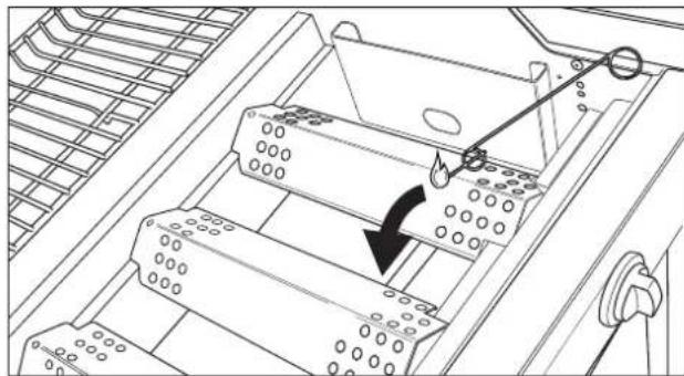
natural_image
Diagram of a mechanical device interior with arrows indicating motion or force direction (no text or symbols)- Postavite kontrolni čvor jednog plamenika na HIGH.

Uvijek za početak upali e jedan glavni plamenik. Nikad nemojte paliti sve glavne plamenike odjednom.
natural_image
Diagram of a fish-shaped structure with internal components and no visible text or symbols
Oštećenja nastala zbog blokiranih plamenika i redukcijskih cijevi sma aju se neodgovarajućim načinom održavanja i nisu pokrivena jamstvom.
11.3.2 KADA JE POTREBNO ČISTITI PLAMENIKE I REDUKCIJSKE CIJEVI?
Morate čistiti plamenike i redukcijs e cijevi ašeg uređaja:
natural_image
Technical line drawing of a mechanical assembly with internal components and directional arrows (no text or symbols)text_image
Exploded view diagram of a household appliance with numbered parts and a color-coded rating scale at the bottom.| SPRING 2002# 223.6922.000 | ||
| 1 | 227.9530.010 | |
| 2 | 227.3002.020 | |
| 3 | 227.9530.030 | |
| 4 | 227.9630.040 | |
| 5 | 227.9530.050 | |
| 6 | 227.9630.060 | |
| 7 | 227.2092.230 | |
| 8 | 227.6930.080 | |
| 9 | 227.6922.010 | |
| 10 | 227.9540.080 | |
| 11 | 227.9540.090 | |
| 12 | 227.6922.020 | |
| 13 | 227.6922.030 | |
| 14 | Not available as spare part | |
| 15 | 227.3002.070 | |
| 16 | 227.6922.040 | |
| 17 | 227.6922.050 | |
| 18 | 227.6922.060 | |
| 19 | 227.9020.550 | |
| 20 | 227.9020.540 | |
| 21 | 227.9530.200 | |
| 22 | 227.9530.210 | |
| 23 | 227.9530.220 | |
| 24 | 227.9530.230 | |
| 25 | 227.3112.030 | |
| 26 | 227.6922.070 | |
| 27 | 227.2092.280 | |
| 28 | 227.9989.460 | |
| 29 | 227.6922.080 | |
| 30 | 227.9900.210 | |
| 31 | 227.9900.230 | |
| 32 | 227.6922.090 | |

natural_image
Technical line drawing of a mechanical frame structure with no visible text or symbols
natural_image
Technical line drawing of a mechanical frame structure with no visible text or symbols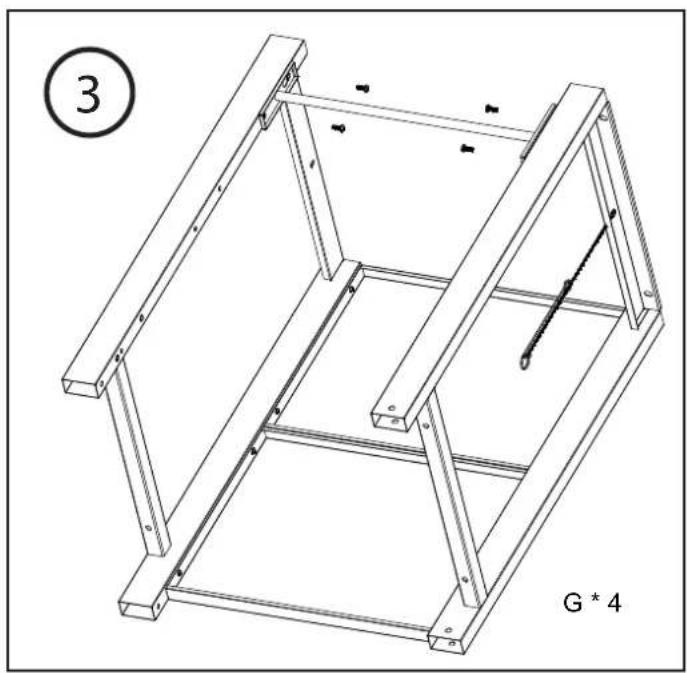
natural_image
Technical line drawing of a mechanical frame structure with no visible text or symbols
text_image
④ G * 4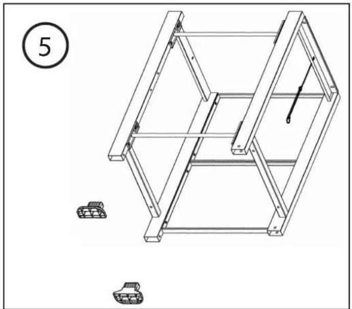
natural_image
Technical line drawing of a mechanical frame structure with two small tank components, no text or symbols present
text_image
6 B * 3 D * 1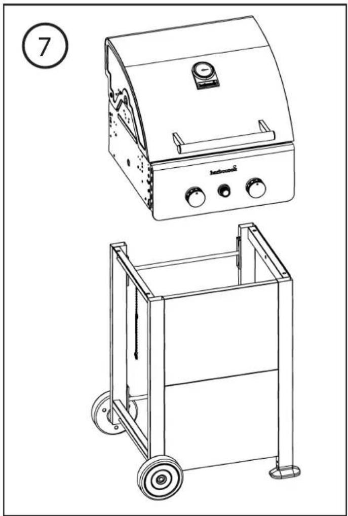
natural_image
Technical line drawings of two industrial appliances: a gas stove and a cart (no text or symbols present)
natural_image
Technical line drawing of a mechanical frame assembly (no text or symbols)
text_image
⑨ H * 4 Jaherwick
text_image
10 C * 2 J * 2
text_image
11
natural_image
Line drawing of a rectangular electronic device casing with mounting brackets and a coiled spring (no text or symbols)
text_image
1314 G * 1 I * 1
natural_image
Technical line drawing of a mechanical device with no visible text or symbols
text_image
15 C * 2 J * 2
text_image
16 H * 4
text_image
1718 C*2 J*2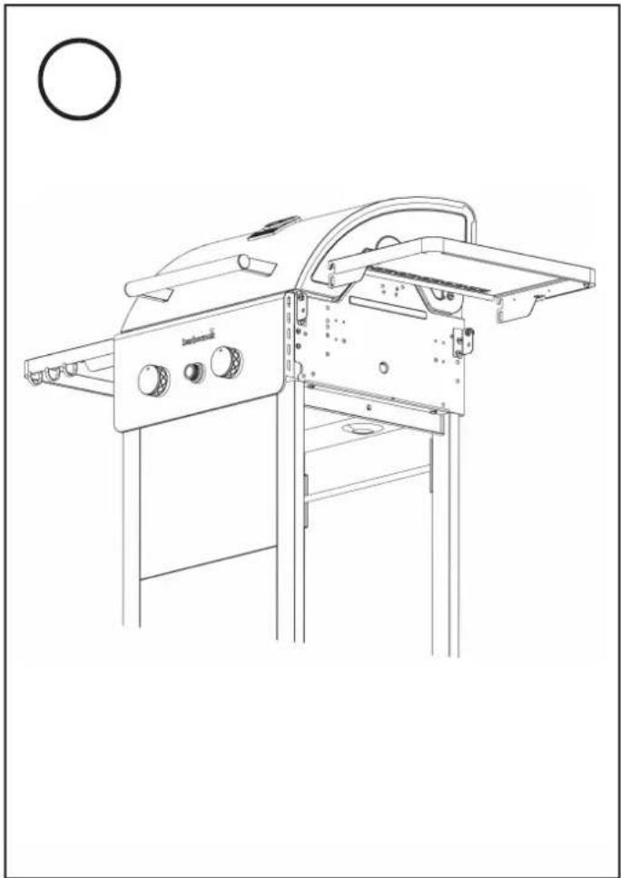
natural_image
Line drawing of a portable electric guitar with control panel and side-mounted stand (no text or symbols)
text_image
1920 C * 2 J * 2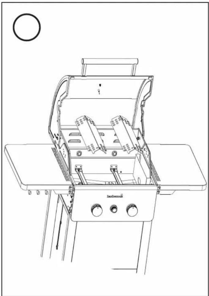
natural_image
Line drawing of a portable electric guitar with control panel and fan (no text or symbols)
text_image
2122 Ambeccoli
natural_image
Line drawing of a portable electric grill with control panel and side table (no text or symbols)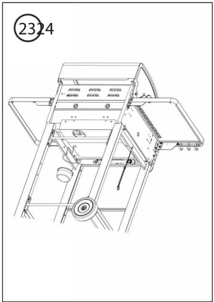
natural_image
Technical line drawing of a mechanical device with no visible text or symbols
natural_image
Line drawing of a portable electric grill with wheels and control panel (no text or symbols)
Home & Garden
Blokkestraat 41A,
B-8550, Zwevegem, Belgium
CE 2531/19
PIN: 2531CS - 0048
text_image
GRILL MASTER barbecookREGISTER NOW & GET ACCESS TO:

text_image
barbcss MY PRODUCERS / BARBDCOMEN EOGON BLACK ACCESSORIES U'ARO, PRAVE NOMATS MARTANTY• Online Product Manuals
• Personalised Grillspiration
• Product Tips & Tricks
• Barbecook Challenges
- Spare Parts Lists
...
WWW.BARBECOOK.COM
Barbecook® is a registered trade mark of SAEY Home & Garden N.V. Blokkestraat 41A, B-8550, Zwevegem, Belgium
