BPS18254BL - Jigsaw AEG - Free user manual and instructions
Find the device manual for free BPS18254BL AEG in PDF.
User questions about BPS18254BL AEG
0 question about this device. Answer the ones you know or ask your own.
Ask a new question about this device
Download the instructions for your Jigsaw in PDF format for free! Find your manual BPS18254BL - AEG and take your electronic device back in hand. On this page are published all the documents necessary for the use of your device. BPS18254BL by AEG.
USER MANUAL BPS18254BL AEG
Original instructions
natural_image
3D rendering of a mechanical cutting tool with orange and silver components (no text or symbols visible)
natural_image
Illustration of four screws and four washers with a document icon on the left (no text or symbols)
natural_image
Three orange 3D geometric shapes (closes and trapezoids) next to two documents with blank text, no visible symbols or text.
natural_image
Simple illustration of an open box with a white upward arrow (no text or symbols)
natural_image
Mechanical assembly with a hand operating a cutting tool, no visible text or symbols
natural_image
Black rectangular electronic component with orange highlights, labeled 'III' in top-left corner (no other text or symbols)
natural_image
Close-up of mechanical components with gear and tools, no visible text or symbols
natural_image
Close-up of a robotic arm with directional arrows indicating movement or force (no text or symbols)
natural_image
Mechanical assembly diagram showing a clamping mechanism with no visible text or symbols
natural_image
Diagram of a mechanical device with directional arrows indicating motion or force (no text or symbols)
natural_image
Close-up of a mechanical device with a golden tool and black components, labeled 'VIII' in the top-left corner (no other text or symbols visible)

natural_image
Close-up of a mechanical assembly with arrows indicating motion or force direction (no text or symbols visible)
natural_image
Mechanical device with internal components and directional arrows, labeled 'XIII' (no readable text or symbols)
natural_image
Mechanical tool with blade and cutting edge, showing motion direction arrows (no text or symbols)

natural_image
Simple line drawing of a wrench with no text or symbols
Accessorio • Acessório Toebehoren • Tilbehør Tilbehør • Tillbehör Lisälaite • Εξαρτήματα Aksesuar • Príslušenstvn Príslušenstv • Wyposażenie Azokat a tartozékokat Oprema • Piederumi Priedas • Tarvikud Дополнитель•Аксесоари Accesoriu•ополнителна опрема • Комплектуючі الملحق
natural_image
Simple illustration of an open box with a white upward arrow on top (no text or symbols)

Not included in standard equipment.
natural_image
Mechanical device with orange tool and black handle, no visible text or symbols

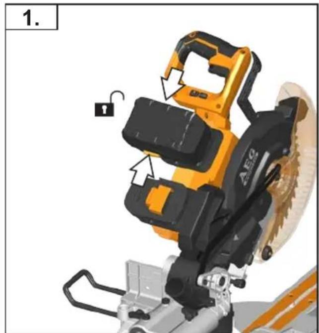
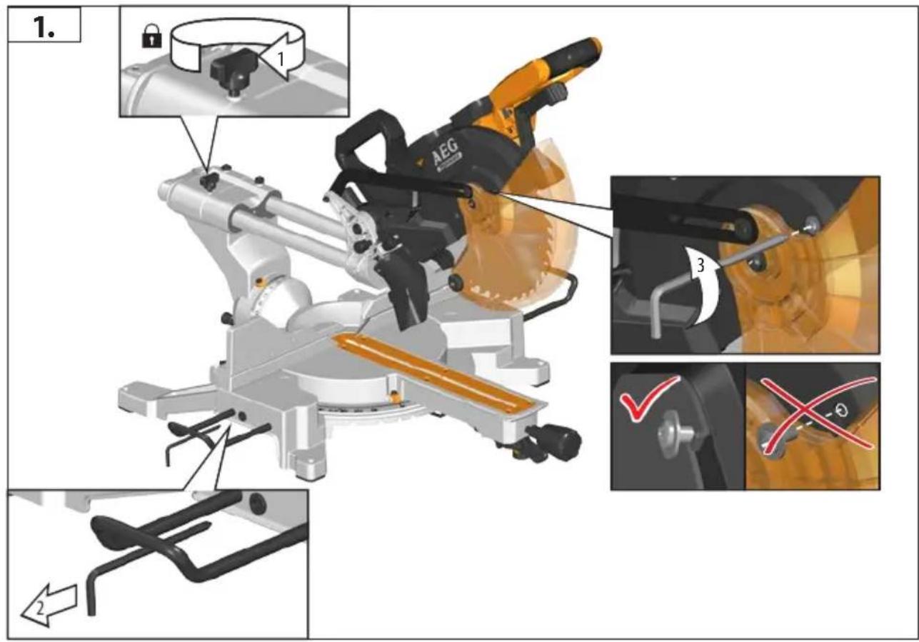
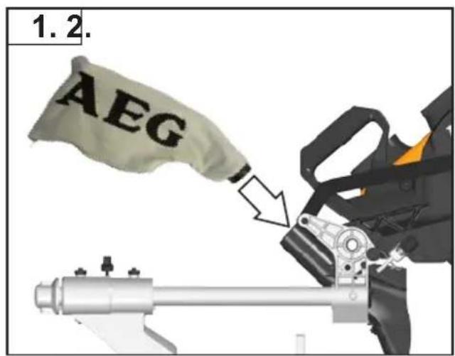
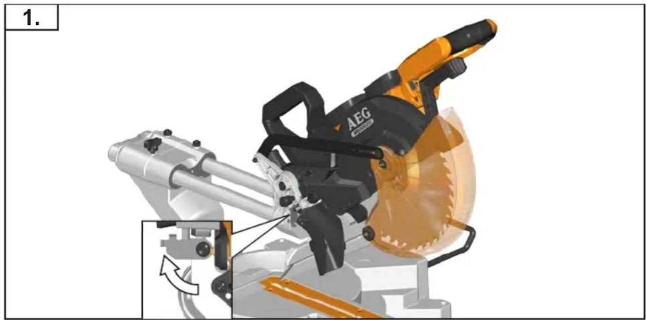
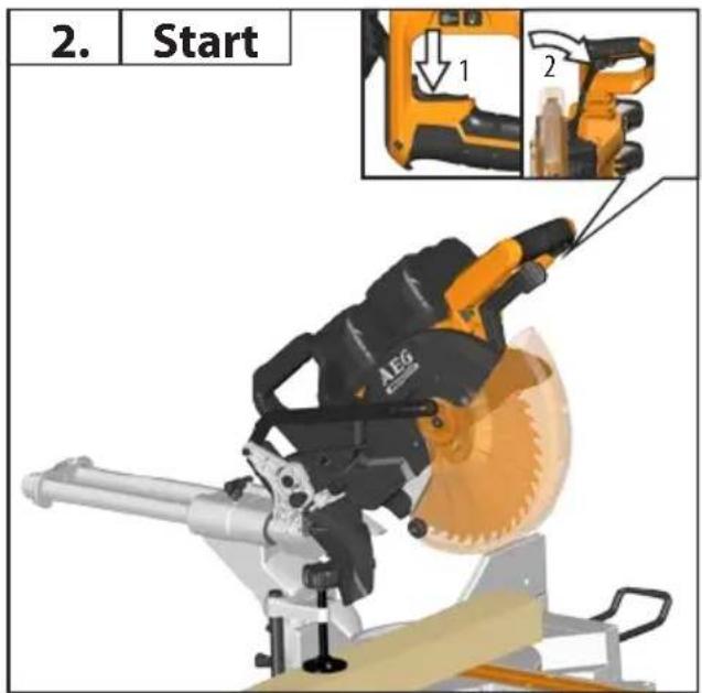
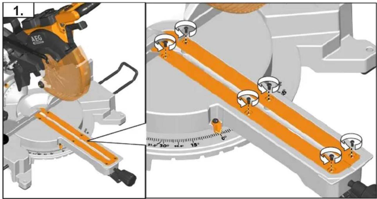
1.
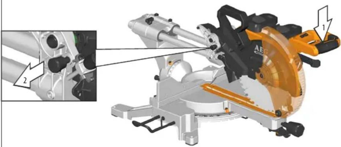
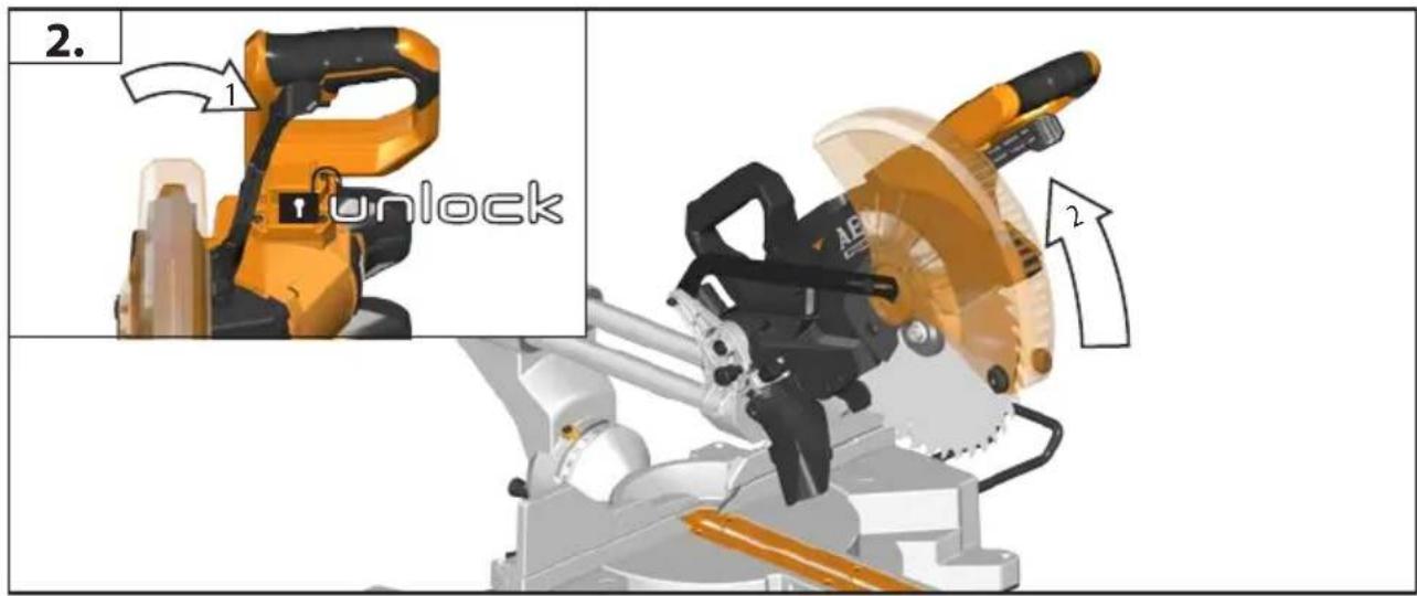
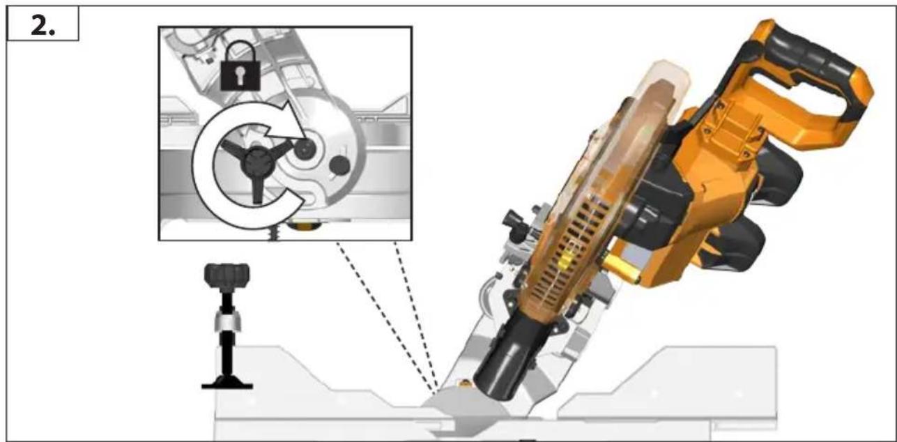
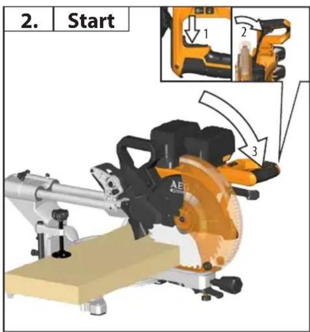
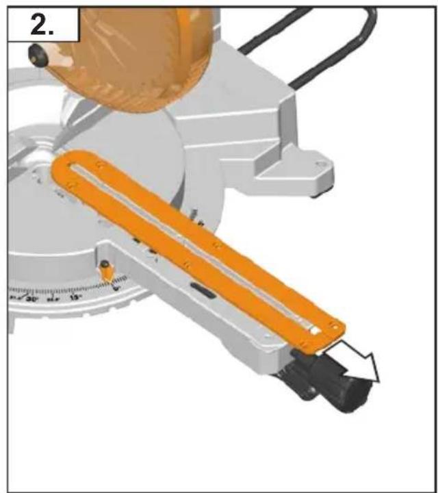
2.
natural_image
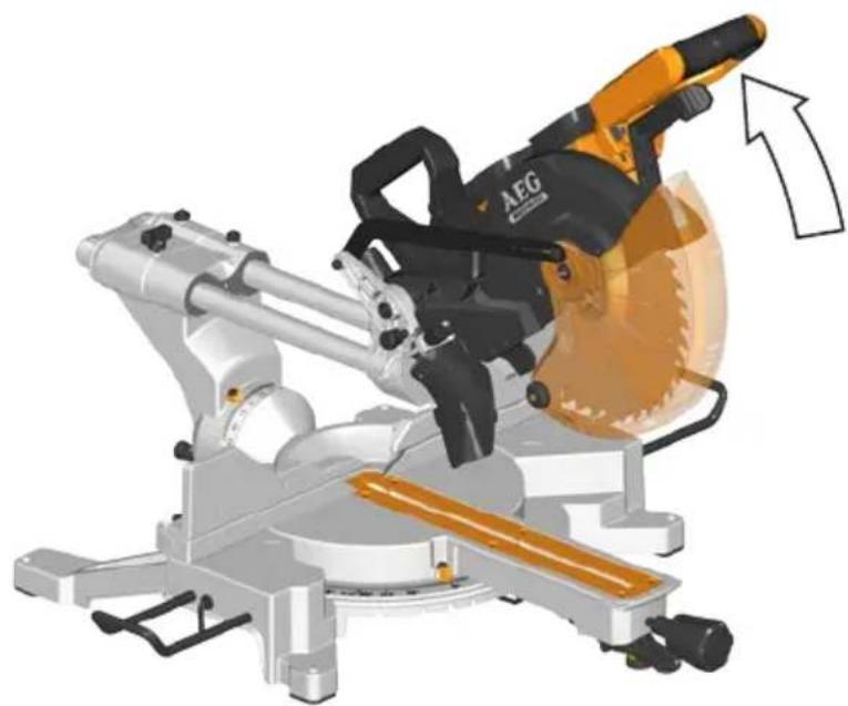
Illustration of a cutting machine with a yellow AEG blade and orange blade, showing mechanical components and an upward arrow (no text or symbols)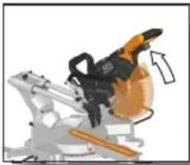
natural_image
Mechanical device with orange tool and black handle, no visible text or symbols


natural_image
Black rectangular electronic component with orange highlights (no text or symbols visible)
natural_image
Close-up of a yellow and black AEG cutting machine with a labeled component (no text or symbols on the machine itself)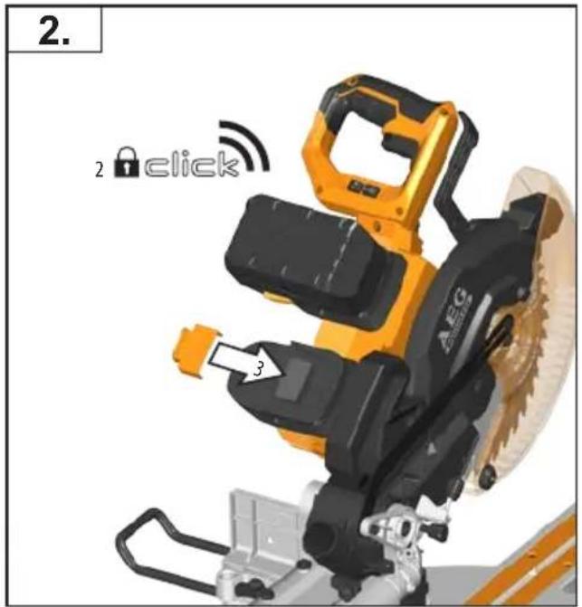

natural_image
Close-up of a yellow and black AEG cutting machine with a white arrow pointing to the blade (no text or symbols visible)
natural_image
Black rectangular electronic component with orange highlights (no visible text or symbols)
natural_image
Illustration of a yellow and black industrial robot with a circular gauge symbol (no text or labels)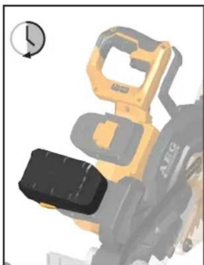
natural_image
3D rendered image of a yellow and black robotic device with a circular gauge symbol (no text or symbols on the device itself)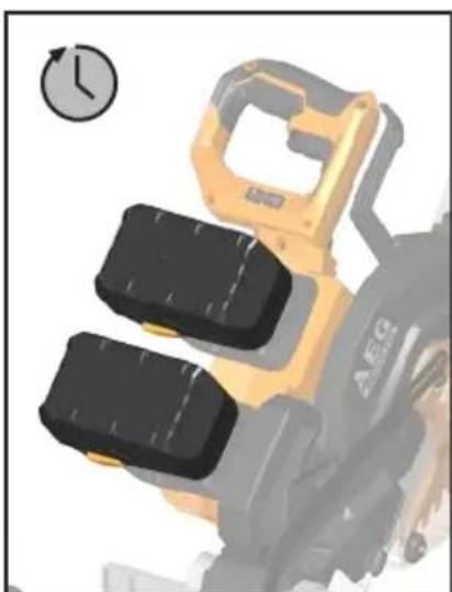
natural_image
Illustration of a yellow AERG robotic device with two black components, no visible text or symbols
natural_image
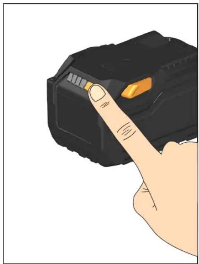
Illustration of a hand pressing down on a black device with a yellow button (no text or symbols visible)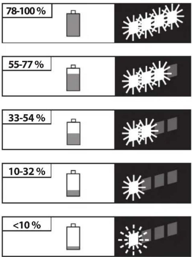
bar
| Range (%) | Percentage (%) | | :--- | :--- | | 78-100% | (no label) | | 55-77% | (no label) | | 33-54% | (no label) | | 10-32% | (no label) | | <10% | (no label) |
natural_image
Close-up of mechanical components with gear and tools (no visible text or symbols)


natural_image
Close-up of mechanical components with gear and lever (no visible text or symbols)


natural_image
Close-up of mechanical components with gear and tools (no visible text or symbols)


natural_image
Close-up of mechanical components with no visible text or symbols


natural_image
Mechanical assembly diagram showing a cutting machine with a yellow AEG tool operating, alongside a close-up of the mechanical component (no text or symbols visible)
natural_image
Close-up of a robotic arm with directional arrows indicating movement or force (no text or symbols visible)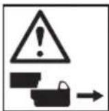
natural_image
Diagram of a cutting machine with a blade and tool, showing alignment and maintenance (no text or symbols)
natural_image
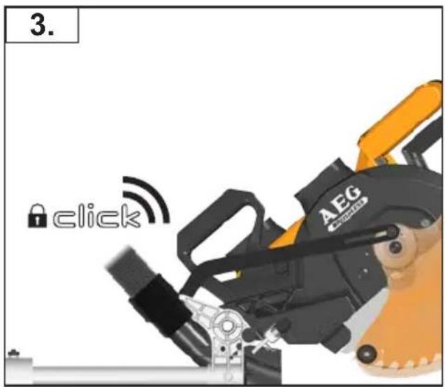
Illustration of a mechanical device with a lock and labeled component (no text or symbols)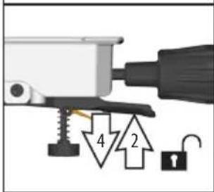
natural_image
Illustration of a computer mouse with a lock and numbered component (no text or symbols)
natural_image
Mechanical assembly diagram showing a clamping mechanism with no visible text or symbols
natural_image
Industrial robotic arm with a black lever and white base, no visible text or symbols
natural_image
Mechanical assembly diagram showing a mounted device with bidirectional arrows indicating movement or force (no text or symbols present)
natural_image
Mechanical assembly diagram showing a rotating component with a circular head and directional arrow (no text or symbols)
natural_image
Solid gray rectangular shape with no text, symbols, or discernible features.
natural_image
Mechanical assembly diagram showing a rotating component with arrows indicating motion (no text or symbols)


natural_image
Mechanical assembly diagram showing a rotating component with motion arrows (no text or symbols)
natural_image
Close-up of a mechanical assembly with a golden tool and black components, no visible text or symbols
natural_image
Mechanical assembly diagram showing a tool interacting with a component, with an inset close-up of a pipe fitting (no text or symbols visible)| A AP 2-200 4931 4472 95 | |
| B AP 300 4931 4472 94 | |
natural_image
Close-up of a mechanical assembly with arrows indicating motion or force direction (no visible text or symbols)
natural_image
AEG cutting machine tool in operation, showing blade and cutting edge details (no text or symbols on the diagram itself)
natural_image
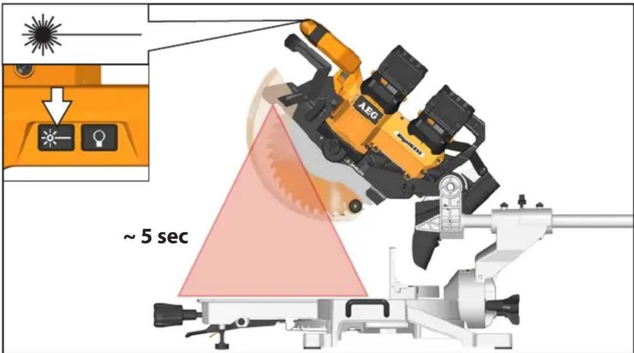
Simple diagram with a diagonal line and two icons: a light bulb and a sunburst symbol (no text or labels)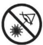
λ:650nm; P<1mW EN60825-1:2014

natural_image
Mechanical assembly diagram showing a cutting tool and gear mechanism (no text or labels)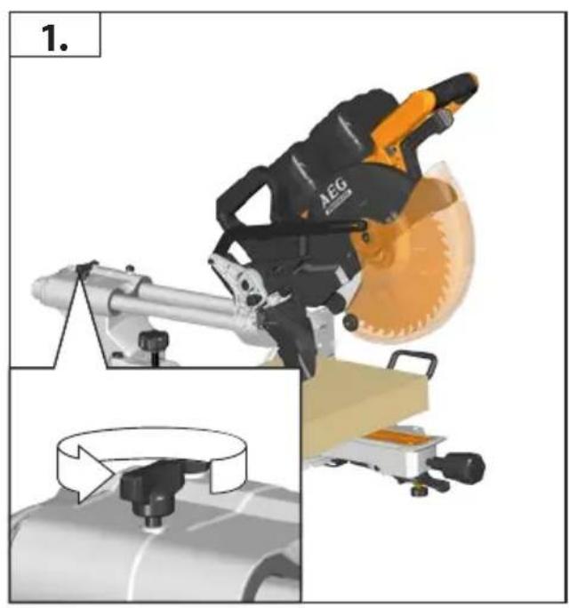
natural_image
3D rendering of a mechanical device with orange and black components, no visible text or symbols
natural_image
Mechanical device with orange and black components, showing motion arrows (no text or symbols)
natural_image
Mechanical tool with orange and black components, showing a cutting machine operation (no text or symbols visible)
natural_image
Simple line drawing of a wrench (no text or symbols)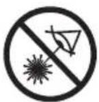
natural_image
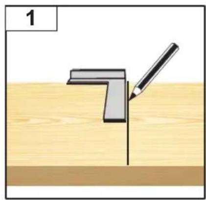
Diagram showing a pencil drawing a corner L-shaped object on a wooden surface (no text or symbols)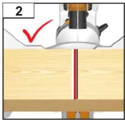
natural_image
Diagram of a mechanical assembly with a tool and red cutting edge (no text or symbols)

natural_image
Close-up of a mechanical component with a lever and circular base (no visible text or symbols)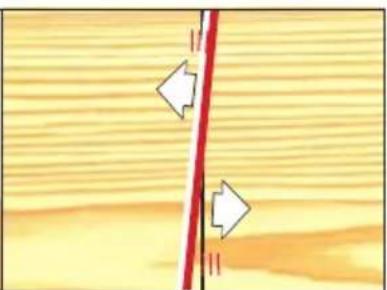
natural_image
Diagram showing a red vertical line intersecting a wooden surface with directional arrows indicating flow or movement (no text or symbols)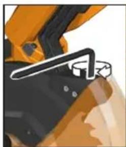
natural_image
Close-up of a yellow excavator's handle and jaw (no visible text or symbols)
natural_image
Simple diagram showing a red vertical line intersecting a textured yellow surface with white arrows pointing downward (no text or symbols)
natural_image
Simple line drawing of a wrench (no text or symbols)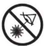


natural_image
Close-up of a hand holding a black object with directional arrows indicating motion (no text or symbols)
natural_image
Diagram showing directional arrows between two vertical lines on a wooden surface (no text or symbols)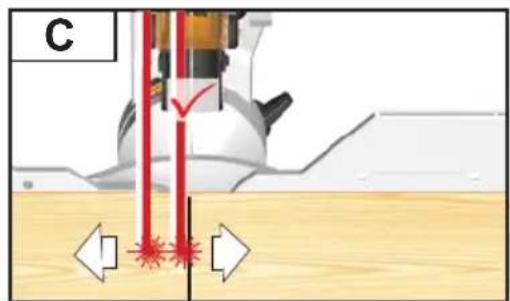

natural_image
Close-up of a hand holding a tool, possibly a pen or stylus, with no visible text or symbols.
natural_image
Pure diagram of a vertical line intersecting a wooden surface with no text, numbers, or symbols
natural_image
Close-up of a hand holding a pen, showing color and texture (no text or symbols visible)
natural_image
Wooden surface with a vertical red line and a white arrow pointing to a feature (no text or symbols)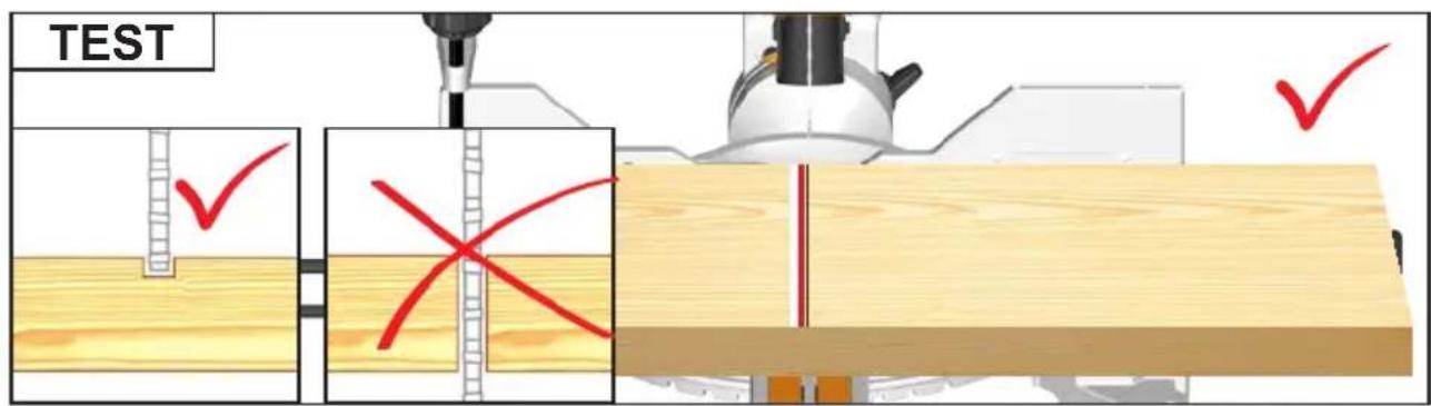

natural_image
Simple line drawing of a wrench (no text or symbols)
natural_image
Simple line drawing of a wrench (no text or symbols)
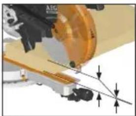
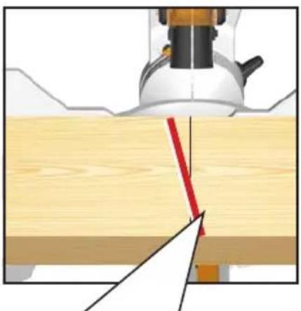
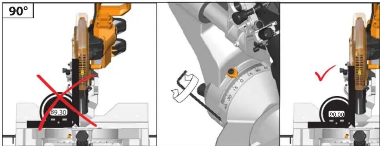
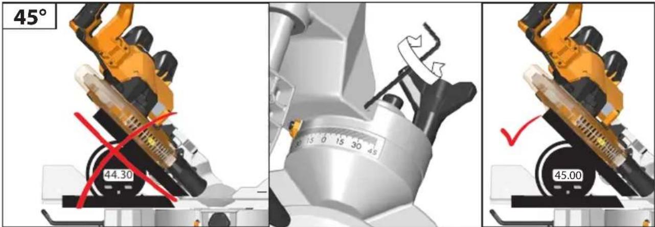
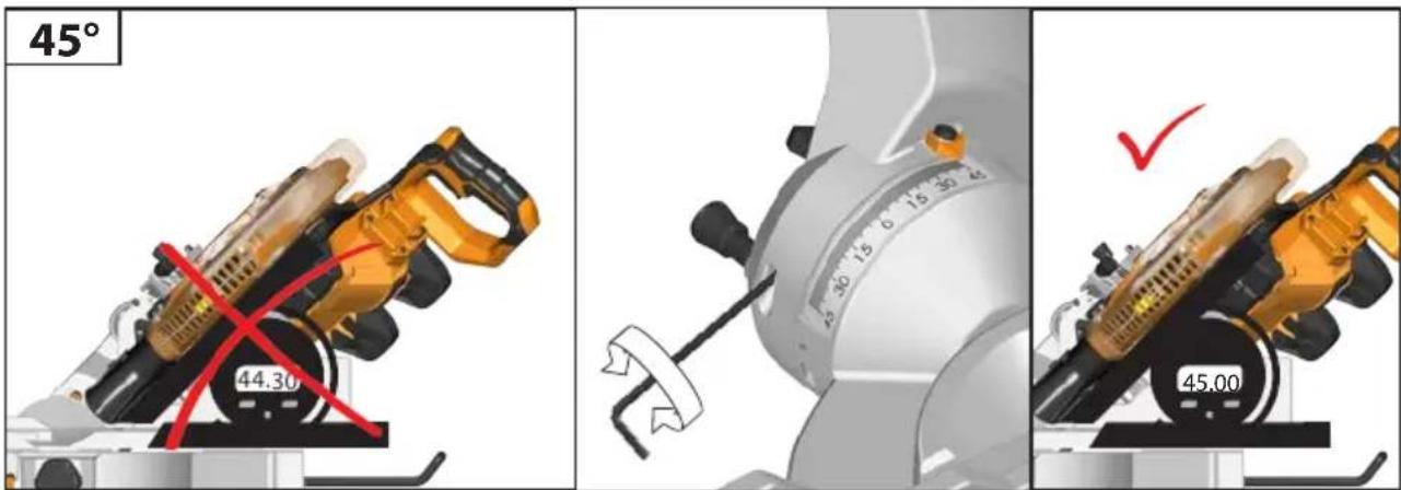
If a correction of the 90° angle of the guide-plate to the saw blade is necessary, use the correction screw.
natural_image
Simple line drawing of a wrench (no text or symbols)

natural_image
Mechanical assembly diagram showing a cutting tool interacting with a workpiece, with no visible text or symbols.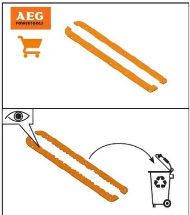
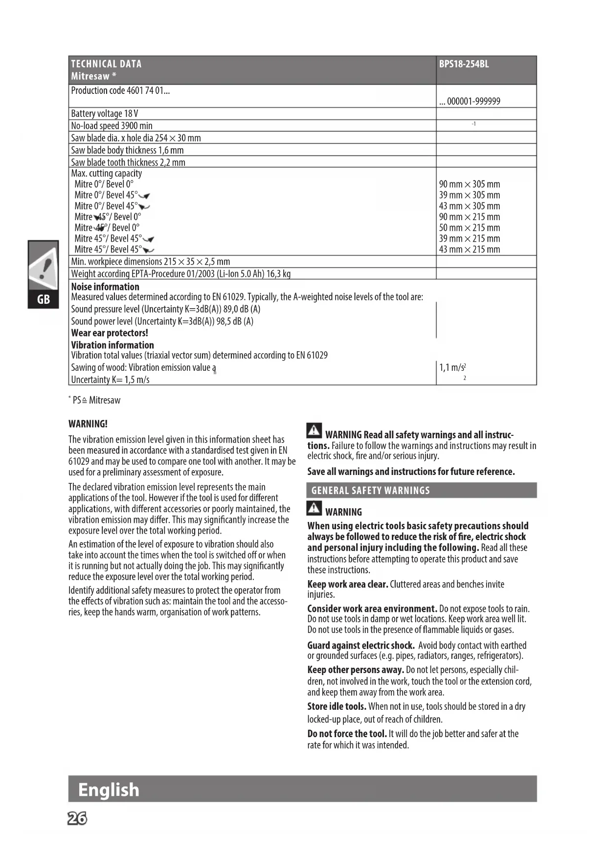
| TECHNICAL DATAMitresaw * | BPS18-254BL |
| Production code 4601 74 01... | ... 000001-999999 |
| Battery voltage 18 V | |
| No-load speed 3900 min | -1 |
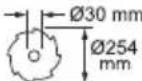
| Saw blade dia. x hole dia 254 × 30 mm | |
| Saw blade body thickness 1,6 mm | |
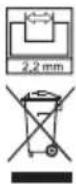
| Saw blade tooth thickness 2,2 mm | |
| Max. cutting capacityMitre 0°/ Bevel 0°Mitre 0°/ Bevel 45°Mitre 0°/ Bevel 45°Mitre 45°/ Bevel 0°Mitre 45°/ Bevel 0°Mitre 45°/ Bevel 45°Mitre 45°/ Bevel 45° | 90 mm × 305 mm39 mm × 305 mm43 mm × 305 mm90 mm × 215 mm50 mm × 215 mm39 mm × 215 mm43 mm × 215 mm |
| Min. workpiece dimensions 215 × 35 × 2,5 mm | |
| Weight according EPTA-Procedure 01/2003 (Li-Ion 5.0 Ah) 16,3 kg | |
| Noise informationMeasured values determined according to EN 61029. Typically, the A-weighted noise levels of the tool are:Sound pressure level (Uncertainty K=3dB(A)) 89,0 dB (A)Sound power level (Uncertainty K=3dB(A)) 98,5 dB (A)Wear ear protectors!Vibration informationVibration total values (triaxial vector sum) determined according to EN 61029Sawing of wood: Vibration emission value a Uncertainty K=1,5 m/s | 1,1 m/s ^2 |
* PS ≅ Mitresaw
WARNING!
The vibration emission level given in this information sheet has been measured in accordance with a standardised test given in EN 61029 and may be used to compare one tool with another. It may be used for a preliminary assessment of exposure.
The declared vibration emission level represents the main applications of the tool. However if the tool is used for different applications, with different accessories or poorly maintained, the vibration emission may differ. This may significantly increase the exposure level over the total working period.
An estimation of the level of exposure to vibration should also take into account the times when the tool is switched off or when it is running but not actually doing the job. This may significantly reduce the exposure level over the total working period.
Identify additional safety measures to protect the operator from the effects of vibration such as: maintain the tool and the accessories, keep the hands warm, organisation of work patterns.

WARNING Read all safety warnings and all instruc-
tions. Failure to follow the warnings and instructions may result in electric shock, fire and/or serious injury.
Save all warnings and instructions for future reference.
GENERAL SAFETY WARNINGS

WARNING
When using electric tools basic safety precautions should always be followed to reduce the risk of fire, electric shock and personal injury including the following. Read all these instructions before attempting to operate this product and save these instructions.
Keep work area clear. Cluttered areas and benches invite injuries.
Consider work area environment. Do not expose tools to rain. Do not use tools in damp or wet locations. Keep work area well lit. Do not use tools in the presence of flammable liquids or gases.
Guard against electric shock. Avoid body contact with earthed or grounded surfaces (e.g. pipes, radiators, ranges, refrigerators).
Keep other persons away. Do not let persons, especially children, not involved in the work, touch the tool or the extension cord, and keep them away from the work area.
Store idle tools. When not in use, tools should be stored in a dry locked-up place, out of reach of children.
Do not force the tool. It will do the job better and safer at the rate for which it was intended.
English
Use the right tool. Do not force small tools to do the job of a heavy duty tool. Do not use tools for purposes not intended, for example, do not use circular saws to cut tree limbs or logs.
Dress properly. Do not wear loose clothing or jewellery, they can be caught in moving parts. Non-skid footwear is recommended when working outdoors. Wear protective hair covering to contain long hair.
Use protective equipment. Use safety glasses. Use face or dust mask if working operations create dust.
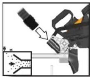
Connect dust extraction equipment. If the tool is provided for the connection of dust extraction and collecting equipment, ensure these are connected and properly used.
Do not abuse the cord. Never yank the cord to disconnect it from the socket. Keep the cord away from heat, oil and sharp edges.
Secure work. Where possible, use clamps or a vice to hold the work. It is safer than using your hand.
Do not overreach. Keep proper footing and balance at all times.
Maintain tools with care. Keep cutting tools sharp and clean for better and safer performance. Follow instruction for lubricating and changing accessories. Inspect tool cords periodically and if damaged, have them repaired by an authorised service facility. Inspect extension cords periodically and replace if damaged. Keep handles dry, clean and free from oil and grease.
Disconnect tools. When not in use, before servicing and when changing accessories such as blades, bits and cutters, disconnect tools from the power supply.
Remove adjusting keys and wrenches. Form the habit of checking to see that keys and adjusting wrenches are removed from the tool before turning it on.
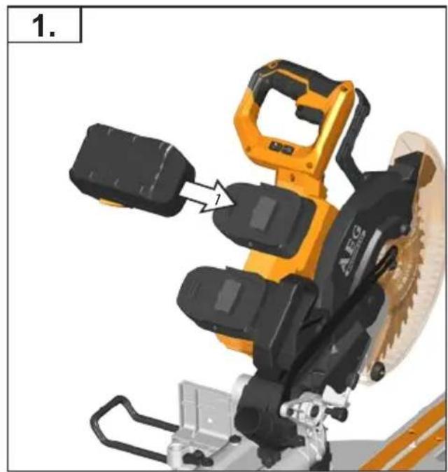
Avoid unintentional starting. Ensure switch is in "off" position when installing battery pack.
Use outdoor extension leads. When the tool is used outdoors, use only extension cords intended for outdoor use and so marked.
Stay alert. Watch what you are doing, use common sense and do not operate the tool when you are tired.
Check damaged parts. Before further use of tool, it should be carefully checked to determine that it will operate properly and perform its intended function. Check for alignment of moving parts, binding of moving parts, breakage of parts, mounting and any other conditions that may affect its operation.
A guard or other part that is damaged should be properly repaired or replaced by an authorised service centre unless otherwise indicated in this instruction manual.
Have defective switches replaced by an authorised service centre. Do not use the tool if the switch does not turn it on and off.
Warning. The use of any accessory or attachment other than the one recommended in this instruction manual may present a risk of personal injury.
Have your tool repaired by a qualified person. This electric tool complies with the relevant safety rules. Repairs should only be carried out by qualified persons using original spare parts otherwise this may result in considerable danger to the user.

MITRE SAW SAFETY WARNINGS
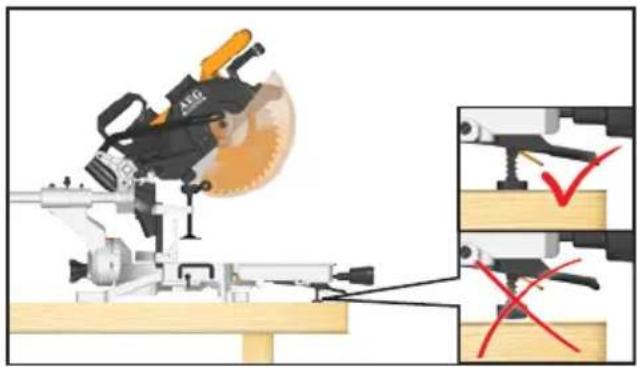
Always clamp the workpiece safely and securely.
Ensure that the machine is always stable and secure (e.g. fixed to a bench).
Always wear ear protectors. Exposure to noise can cause hearing loss.
Always wear safety goggles when using the machine. It is recommended to wear gloves for handling blades and rough material, as well as sturdy non-slip shoes which also protect the feet from workpieces that may fall from the cutting area.
Always remove the plug or battery pack before carrying out any adjustment, maintenance or cleaning on the machine.
Ensure the machine is switched off before installing or removing the battery pack.
Do not stand in a line with the saw blade in front of the machine.
Always stand aside of the saw blade.
Keep hands, fingers, and arms away from the rotating saw blade. Never reach into the area near the blade, unless the blade has completely stopped.
Before use, thoroughly check the tool for any damage or material fatigue. Repairs should only be carried out by authorised service agents.
Always use the guards on the machine. Do not use the machine if the guards are not in place and working correctly.
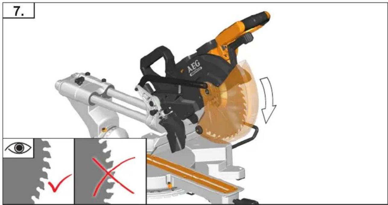
Do not clamp the protective swing guard.
If the workpiece or blade becomes jammed, turn the mitre saw off. Wait for all moving parts to stop and disconnect the plug from the power source and/or remove the battery pack. Then work to free the jammed material.
Never alter of modify the saw or its function. Your safety may be compromised.
Do not use saw blades which are cracked, damaged, or deformed. Do not use saw blades made of high-speed steel.
Only use saw blades which are sharp. Replace blunt blades with a new replacement.
Use a blade holder or wear gloves when handling a saw blade.
Always use blades with correct size and shape of arbour holes.
Blades that do not match the mounting hardware of the saw will run eccentrically, causing loss of control.
Use only woodworking blades specified in this manual, which comply with EN 847-1.
Do not use any flanges, washers, and nuts to secure the saw blade other than those supplied or indicated in the instruction manual.
It is essential to adhere to the maximum speed specified on the saw blade.
It is necessary to select a saw blade which is suitable for the material being cut.
Never use the mitre saw to cut materials other than those specified in the intended use section in this manual.
Replace the table insert when worn or damaged.
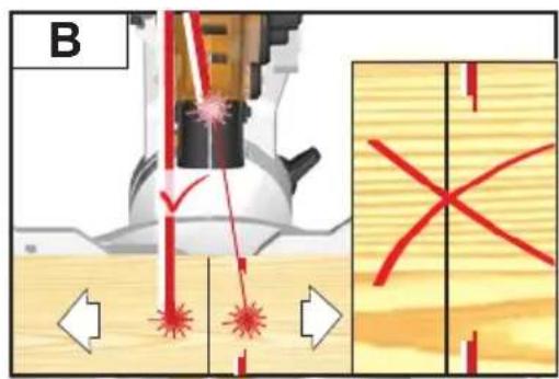
Before work, make a dummy cut without the motor turned on so the position of the blade, operation of the guards with respect to other machine parts, and workpiece may be checked.
Refrain from removing any cut-offs or other parts of the workpiece from the cutting area whilst the machine is running and the saw head is not in the rest position.
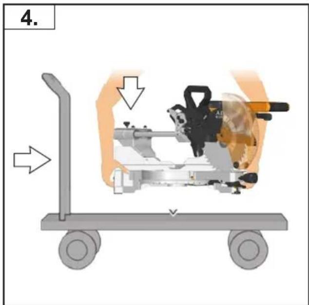
When transporting the machine, use only transportation devices and never use guards for handling or transportation.
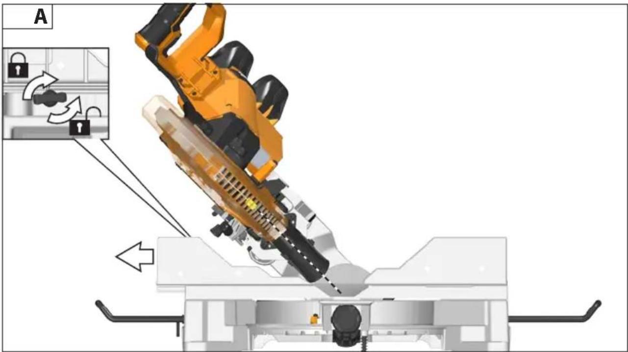
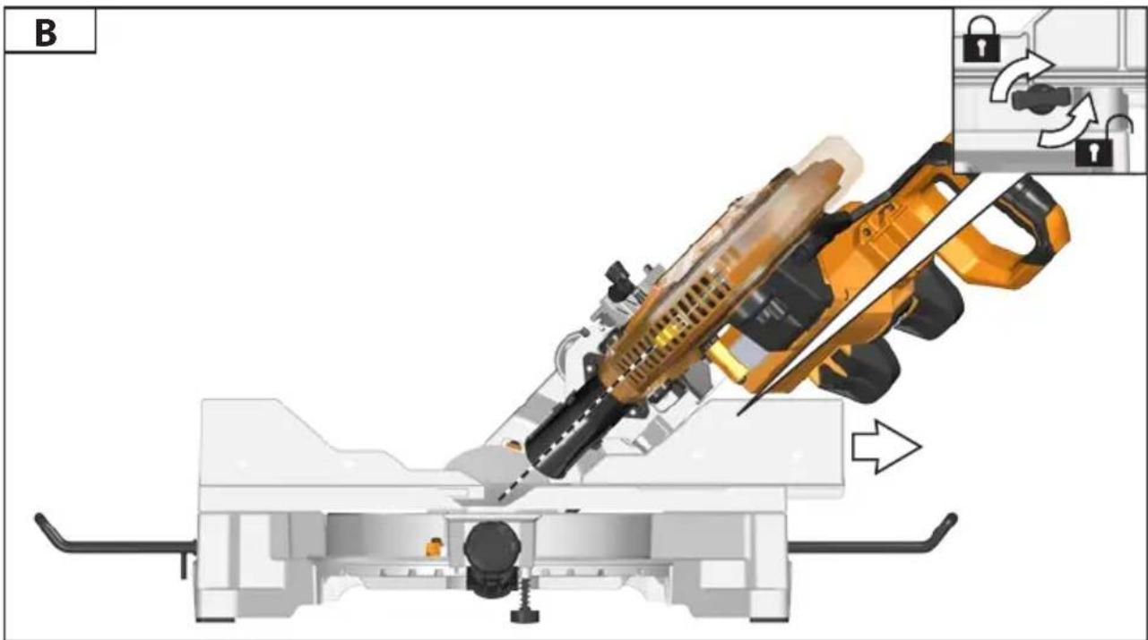
The handle lock must always be engaged when transporting the mitre saw.
Keep the floor area free of loose material e.g. chips and cut-offs.
Long workpieces must be adequately supported.
Stock having a round or irregular cross section (such as firewood) which cannot be clamped securely by the provided clamp must not be cut. When sawing into the edge of thin or layered stock, a suitable auxiliary fence must be used to provide support.
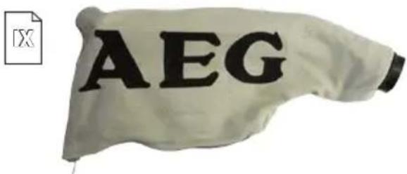
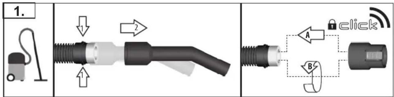
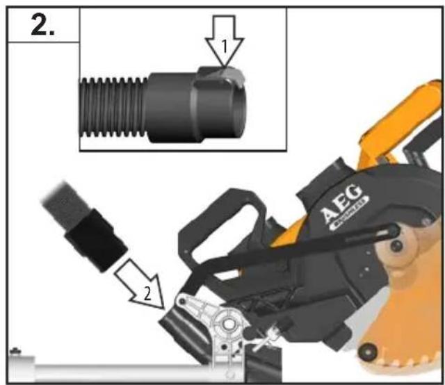
The dust produced when using this tool may be harmful to health. Do not inhale the dust. Use a dust absorption system and wear a suitable dust protection mask. Remove deposited dust thoroughly, e.g. with a vacuum cleaner.
Connect the saw to a dust-collecting device when sawing wood. Do not replace the LED or laser with a different type. Any repairs must only be carried out by the manufacturer or authorised service agent.
Do not use saw blades not corresponding to the key data given in these instructions for use.
Transport and store the tools in a suitable receptacle;
Any faults with the machine, including any related to the safeguard or the saw blades, must be reported to the persons in charge of safety as soon as the faults are discovered.
When performing mitre, bevel or compound mitre cuts, adjust the sliding fence to ensure the correct clearance from the blade.
Adapt the feed speed to avoid overheating the blade tips and to avoid melting plastic materials during cutting.
WARNING Do not replace the LED with a different type.
SAFETY INSTRUCTIONS FOR WOOD CUTTING BLADE
Please read the manual and instructions carefully before using the saw blade and the machine.
The machine must be in good condition, the spindle without deformation and vibration.
Do not use the saw without the guards in position, keep guards in good working order and properly maintained.
Ensure the operator is adequately trained in safety precautions, adjustment, and operation of the machine.
Always wear goggles and ear protection when using the machine. It is recommended to wear gloves, sturdy non-slip shoes and apron.
Before using any accessory, consult the instruction manual. The improper use of an accessory can cause damage and increase the potential for injury.
Use only blades specified in this manual, complying with EN 847-1.
Observe the maximum speed marked on the saw blade. Ensure the speed marked on the saw blade is at least equal to the speed marked on the saw.
Always use blades with correct size and shape of arbour holes.
Blades that do not match the mounting hardware of the saw will run eccentrically, causing loss of control.
Do not use blades of larger or smaller diameter other than recommended. Do not use any spacers to make the blade fit onto the spindle.
Check the tips of the saw blade for damage or abnormal appearance before each use. Tips that are damaged or loose can become flying objects in use and increase the chance of personal injury.
Do not use cracked or distorted saw blades. Do not use saw blades that are damaged or deformed.
Scrap the saw blade if damaged, deformed, distorted or cracked, repairing is not permitted.
Do not use HSS blades.
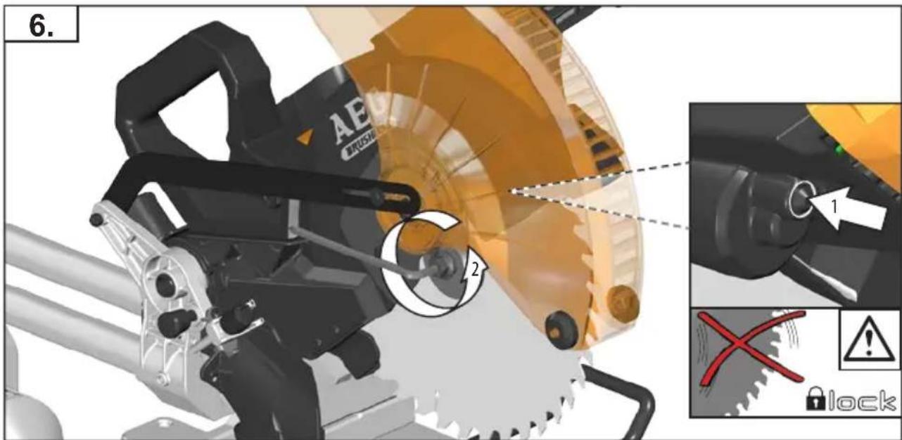
Ensure the saw blade is mounted correctly, tighten the arbor nut securely before use (tightening torque approx. 12 Nm).
Fastening screw and nuts shall be tightened using the appropriate spanner, etc.
Extension of the spanner or tightening using hammer blows is not permitted.
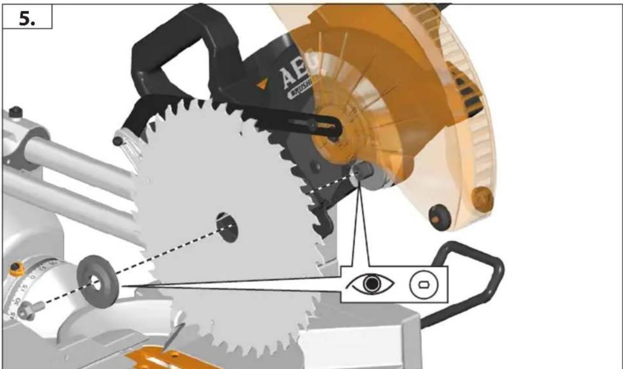
Make sure the blade and flanges are clean and the recessed sides of the collar are against the blade.
Make sure the blade rotates in the correct direction.
Before work, make a dummy cut without the motor turned on so the position of the blade, operation of the guards with respect to other machine parts and workpiece may be checked.
Never leave the machine unattended.
Do not apply lubricants on the blade when it is running.
Never perform any cleaning or maintenance work when the machine is still running and the head is not in the rest position.
Never attempt to stop a machine in motion rapidly by jamming a tool or other means against the blade, serious accidents can be caused unintentionally in this way.
Disconnect the saw from the mains supply or remove battery pack before changing blades or carrying out maintenance.
Pay attention to blade packing and unpacking, it is easy to be injured by the sharp blade tips.
Use a blade holder or wear gloves when handling a saw blade.
Keep and store the blade in original packaging or other suitable packaging, keep in dry conditions and away from chemicals which may damage the blade.
LASER SAFETY RULES
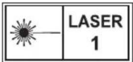
The laser radiation used in this saw is Class 1 with maximum <1mW and 650nm wavelengths. Do not view directly with optical instruments. Failure to comply with the rules could result in serious personal injury.
Do not stare into beam during operation.
Do not project the laser beam directly into the eyes of others. Serious eye injury could result.
Do not place the laser in a position that may cause anyone to stare into the laser beam intentionally or unintentionally.
Do not use optical tools to view the laser beam.
Do not operate the laser around children or allow children to operate the laser.
Do not attempt to repair the laser device by yourself.
Do not attempt to change any parts of the laser device by yourself.
Any repairs must only be carried out by the laser manufacturer or authorized service agent.
WARNING Do not replace the installed laser with a different type.
Do not point laser at reflective surfaces,
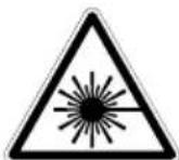
Avoid exposure to laser radiation. Laser may emit hazardous radiation.
English
SPECIFIED CONDITIONS OF USE
The slide compound mitre saw is intended for sawing solid and bonded wood with or without glued veneer, plastics, and materials similar to wood.
The slide compound mitre saw is intended to be used only by adult operators who have read the instruction manual and understand the risks and hazards.
The slide compound mitre saw is designed to be fixed at the base to a solid bench top. If the base is not securely fixed, the whole machine may move during cutting operations, which increases the possibility of serious personal injury.
The slide compound mitre saw is designed make bevel and mitre cuts. The capacities for the various cuts are provided in the product specifications in this manual.
The slide compound mitre saw is to be used in dry conditions, with excellent ambient lighting and adequate ventilation.
The slide compound mitre saw is intended for consumer use and should only be used as described above and is not intended for any other purpose.
RESIDUAL RISK
Even when the slide compound mitre saw is used as prescribed, it is still impossible to completely eliminate certain residual risk factors. The following hazards may arise and the operator should pay special attention to avoid the following:
- Risk of contact with uncovered parts of the rotating saw blade.
- Kick-back of work pieces or parts of work pieces due to improper adjustment or handling.
- Catapulting of faulty carbide tips from the saw blade. Wear Eye protection at all times.
- Damage to the respiratory system. Wear respiratory protection masks containing filters appropriate to the materials being worked. Ensure adequate workplace ventilation. Do not eat, drink or smoke in the work area.
- Damage to hearing if effective hearing protection is not worn.
WARNING Dust from certain paints, coatings, and materials may cause irritation or allergic reactions. Dust from wood such as oak, beech, MDF, and others are carcinogenic. Materials containing asbestos should only be worked on or processed by qualified specialist operators.
WARNING Injuries may be caused or aggravated by prolonged use of a tool. When using any tool for prolonged periods, ensure you take regular breaks.
BATTERIES
Battery packs which have not been used for some time should be recharged before use.
Temperatures in excess of 50^ C ( 122^ F) reduce the performance of the battery pack. Avoid extended exposure to heat or sunshine (risk of overheating).
The contacts of chargers and battery packs must be kept clean.
For an optimum life-time, the battery packs have to be fully charged, after use.
To obtain the longest possible battery life remove the battery pack from the charger once it is fully charged.
For battery pack storage longer than 30 days: Store the battery pack where the temperature is below 27^ C and away from moisture. Store the battery packs in a 30% - 50% charged condition Every six months of storage, charge the pack as normal.
Battery acid may leak from damaged batteries under extreme load or extreme temperatures. In case of contact with battery acid wash it off immediately with soap and water. In case of eye contact rinse thoroughly for at least 10 minutes and immediately seek medical attention.
Do not store the battery pack together with metal objects (short circuit risk).
Do not dispose of used battery packs in the household refuse or by burning them. AEG Distributors offer to retrieve old batteries to protect our environment.
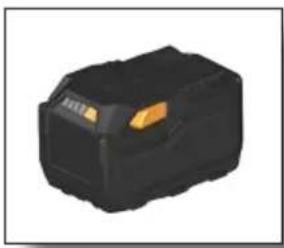
BATTERY AND CHARGER
Compatible battery pack (not included): System GBS
Compatible charger (not included): System GBS
Use only System GBS chargers for charging System GBS battery packs. Do not use battery packs from other systems.
TRANSPORTING LITHIUM BATTERIES
Lithium-ion batteries are subject to the Dangerous Goods Legislation requirements.
Transportation of those batteries has to be done in accordance with local, national and international provisions and regulations.
The user can transport the batteries by road without further requirements.
Commercial transport of Lithium-Ion batteries by third parties is subject to Dangerous Goods regulations. Transport preparation and transport are exclusively to be carried out by appropriately trained persons and the process has to be accompanied by corresponding experts.
When transporting batteries:
Ensure that battery contact terminals are protected and insulated to prevent short circuit. Ensure that battery pack is secured against movement within packaging. Do not transport batteries that are cracked or leak. Check with forwarding company for further advice
BATTERY PACK PROTECTION
In extremely high torque, binding, stalling and short circuit situations that cause high current draw, the tool will vibrate for about 5 seconds, the fuel gauge will flash, and then the tool will turn OFF. To reset, release the trigger.
Under extreme circumstances, the internal temperature of the battery pack could raise too much. If this happens, the fuel gauge will flash until the battery pack cooled down. After the lights go off, the work may continue.
Place the battery on the charger to charge and reset it.
MAINTENANCE
Do not modify this saw in any way or use accessories not approved by the manufacturer. Your safety and that of others may be compromised.
Do not use the saw if any switches, guards or other function of this saw does not work as it is intended to. Return to an authorised service centre for professional repair or adjustment.
Do not make any adjustments whilst the saw blade is in motion.
Removed the battery pack before making adjustments, lubricating or when doing any maintenance on the machine.
Before and after each use, check your saw for damage or broken parts and keep it in top working condition by replacing parts immediately with spares approved by the manufacturer.

The blade is very hot after use, wear gloves or allow to cool before maintenance or cleaning procedures.
Clean out accumulated dust using a brush or vacuum cleaner. Do not use compressed air.
To assure safety and reliability, all repairs, including changing brushes, should be performed by an authorised service centre.
Be sure to disconnect the tool from the power supply before attaching or removing the saw blade.
Clean tool and guarding system with dry cloth.
The ventilation slots of the machine must be kept clear at all times.
REPLACEMENT PARTS
Use only AEG accessories and spare parts. Should components need to be replaced which have not been described, please contact one of our AEG service agents (see our list of guarantee/service addresses).
If needed, an exploded view of the tool can be ordered. Please state the Article No. as well as the machine type printed on the label and order the drawing at your local service agents or directly at: Techtronic Industries GmbH, Max-Eyth-Straße 10, 71364 Winnenden, Germany.
EC-DECLARATION OF CONFORMITY
We declare under our sole responsibility that the product described under "Technical Data" fulfills all the relevant provisions of the directives
2011/65/EU
2006/42/EC
2014/30/EU
and the following harmonized standards have been used.
EN 61029-1:2009 + A11:2010
EN 61029-2-9:2012 + A11:2013
EN 55014-1:2006+A1:2009+A2:2011
EN 55014-2: 1997+A1:2001+A2:2008
EN 50581:2012

Winnenden, 2016-12-02
Alexander Krug / Managing Director
Authorized to compile the technical file
Techtronic Industries GmbH
Max-Eyth-Straße 10, 71364 Winnenden, Germany
SYMBOLS

CAUTION! WARNING! DANGER!

Remove the battery pack before starting any work on the appliance.

Please read the instructions carefully before starting the machine.

Always wear goggles when using the machine.

Wear ear protectors!

Wear gloves!

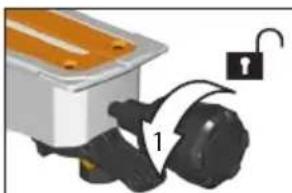
Open Screw
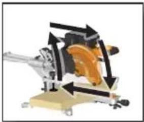
Rotation direction

Always keep hands away from the path of the saw blade.

This tool is only suitable for indoor use. Never expose tool to rain.

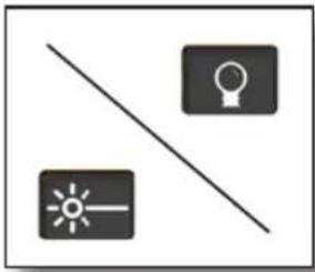
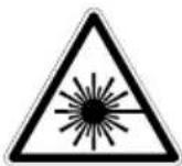
Do not stare into beam.

This product corresponds to the laser class 1 in accordance with EN 60825-1:2014.

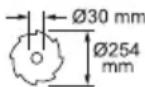
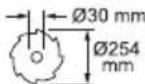
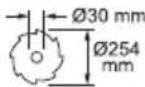
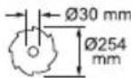
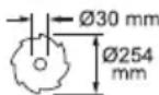
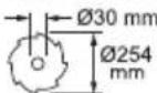
30 mm Ø254 Saw blade dia. x hole dia

Rotation direction

Blade teeth

Width of cut

Do not dispose of electric tools together with household waste material. Electric tools and electronic equipment that have reached the end of their life must be collected separately and returned to an environmentally compatible recycling facility. Check with your local authority or retailer for recycling advice and collection point.

European Conformity Mark

UkrSEPRO Conformity Mark

EurAsian Conformity Mark
Winnenden, 2016-12-02
Alexander Krug / Managing Director
Max-Eyth-Straße 10, 71364 Winnenden, Germany
SYMBOLE

This product corresponds to the laser class 1 in accordance with EN 60825-1:2014.

∅254 Sägeblatt-∅ x Bohrungs-∅

Drehrichtung

Sägeblattzähne

Schnittbreite
Batterie compatible (non inclus): System GBS
Chargeur compatible(non inclus): System GBS
DÉCLARATION CE DE CONFORMITÉ
Winnenden, 2016-12-02
Alexander Krug / Managing Director
Max-Eyth-Straße 10, 71364 Winnenden, Germany
SYMBOLES

ATTENTION! AVERTISSEMENT! DANGER!

This product corresponds to the laser class 1 in accordance with EN 60825-1:2014.

0 mm Ø254 mm
Winnenden, 2016-12-02

Alexander Krug / Managing Director
Max-Eyth-Straße 10, 71364 Winnenden, Germany
SIMBOLI

ATTENZIONE! AVVERTENZA! PERICOLO!

This product corresponds to the laser class 1 in accordance with EN 60825-1:2014.
Winnenden, 2016-12-02
Alexander Krug / Managing Director
Max-Eyth-Straße 10, 71364 Winnenden, Germany
Español
SÍMBOLOS

This product corresponds to the laser class 1 in accordance with EN 60825-1:2014.

30 mm Ø254 mm
Disco de sierra - ø x orificio ø

Winnenden, 2016-12-02
Alexander Krug / Managing Director
Max-Eyth-Straße 10, 71364 Winnenden, Germany
SYMBOLE

ATENÇÃO! PERIGO!

This product corresponds to the laser class 1 in accordance with EN 60825-1:2014.
Winnenden, 2016-12-02

Alexander Krug / Managing Director
Max-Eyth-Straße 10, 71364 Winnenden, Germany
SYMBOLLEN

OPGELET! WAARSCHUWING! GEVAAR!

This product corresponds to the laser class 1 in accordance with EN 60825-1:2014.

30 mm
Ø254 mm
Zaagblad ø x boring ø

Draairichting

zaagbladtanden

Freesbreedte
EurAsian-symbol van overeenstemming.


Winnenden, 2016-12-02

Alexander Krug / Managing Director
Max-Eyth-Straße 10, 71364 Winnenden, Germany
SYMBOLER

VIGTIGT! ADVARSEL! FARE!

This product corresponds to the laser class 1 in accordance with EN 60825-1:2014.


Savklinge-ø x hul-ø

Omdrejningsretning

klinge tænder

Skærebredde
Winnenden, 2016-12-02

Alexander Krug / Managing Director
Max-Eyth-Straße 10, 71364 Winnenden, Germany
SYMBOLER

OBS! ADVARSEL! FARE!

This product corresponds to the laser class 1 in accordance with EN 60825-1:2014.
Sagblad-ø x hull-ø

Rotasjonsretningen

knivtenner
Skjærebredde
Winnenden, 2016-12-02
Alexander Krug / Managing Director
Max-Eyth-Straße 10, 71364 Winnenden, Germany
SYMBOLER

OBSERVERA! WARNING! FARA!

This product corresponds to the laser class 1 in accordance with EN 60825-1:2014.
Sågklinga-ø x hål-ø

Rotationsriktning

blad tänder

Skärbredd

Winnenden, 2016-12-02
Alexander Krug / Managing Director
Max-Eyth-Straße 10, 71364 Winnenden, Germany
SYMBOLIT

HUOMIO! VAROITUS! VAARA!

This product corresponds to the laser class 1 in accordance with EN 60825-1:2014.
Winnenden, 2016-12-02
Alexander Krug / Managing Director
Max-Eyth-Straße 10, 71364 Winnenden, Germany
ΣΥΜΒΟΛΑ

This product corresponds to the laser class 1 in accordance with EN 60825-1:2014.

30 mm
Ø254 mm
Winnenden, 2016-12-02

Alexander Krug / Managing Director
Max-Eyth-Straße 10, 71364 Winnenden, Germany
SEMBOLLER

DİKKAT! UYARI! TEHLİKE!

This product corresponds to the laser class 1 in accordance with EN 60825-1:2014.

This product corresponds to the laser class 1 in accordance with EN 60825-1:2014.
GmbH, Max-Eyth-Straße 10, 71364 Winnenden, Germany.
CE-PROHLÁŠENÍ O SHODĚ
Winnenden, 2016-12-02

Alexander Krug / Managing Director
Max-Eyth-Straße 10, 71364 Winnenden, Germany
SYMBOLY

POZOR! VAROVÁN! NEBEZPEČÍ!

CE - VYHLÁSENIE KONFORMITY
Winnenden, 2016-12-02

Max-Eyth-Straße 10, 71364 Winnenden, Germany
SYMBOLY

POZOR! NEBEZPEČENSTVO!

This product corresponds to the laser class 1 in accordance with EN 60825-1:2014.


Priemer pílového listu x priemer diery

Smer otáčania

ostrie zuby

Šírka rezu
Winnenden, 2016-12-02
Alexander Krug / Managing Director
Max-Eyth-Straße 10, 71364 Winnenden, Germany
SYMBOLE

This product corresponds to the laser class 1 in accordance with EN 60825-1:2014.
Winnenden, 2016-12-02

Alexander Krug / Managing Director
Max-Eyth-Straße 10, 71364 Winnenden, Germany
SZIMBÓLUMOK

FIGYELEM! FIGYELMEZTETÉS! VESZÉLY!

This product corresponds to the laser class 1 in accordance with EN 60825-1:2014.

0 mm
21254
mm
UPORABA V SKLADU Z NAMEMBNESTJO
Winnenden, 2016-12-02
Alexander Krug / Managing Director
Max-Eyth-Straße 10, 71364 Winnenden, Germany
SIMBOLI

POZOR! OPOZORILO! NEVARNO!

This product corresponds to the laser class 1 in accordance with EN 60825-1:2014.

List žage ø x vrtalni ø

Smer vrtenja

rezilo zobje

Širina reza
Winnenden, 2016-12-02
Alexander Krug / Managing Director
Ovlašten za formiranje tehničke dokumentacije.
Techtronic Industries GmbH
Max-Eyth-Straße 10, 71364 Winnenden, Germany
SIMBOLI

PAŽNJA! UPOZORENIE! OPASNOST!

This product corresponds to the laser class 1 in accordance with EN 60825-1:2014.


List pile-ø x Bušenje-ø

Smjer vrtnje

blade zubi

Širina rezanja
Winnenden, 2016-12-02
Alexander Krug / Managing Director
Max-Eyth-Straße 10, 71364 Winnenden, Germany
SIMBOLI

UZMANİBU! BİSTAMI!

This product corresponds to the laser class 1 in accordance with EN 60825-1:2014.


Winnenden, 2016-12-02

Alexander Krug / Managing Director Igaliotas parengti techninius dokumentus.
Techtronic Industries GmbH
Max-Eyth-Straße 10, 71364 Winnenden, Germany
SIMBOLIAI

DÉMESIO! JSPÉJIMAS! PAVOJUS!

This product corresponds to the laser class 1 in accordance with EN 60825-1:2014.


Pjovimo disko ø x grężinio ø

Sukimosi kryptis

ašmenys dantys

Pjūvio plotis
ÜLDISED OHUTUSJUHISED

TÄHELEPANU
SPETSIAALSED TURVAJUHISED LASER
Winnenden, 2016-12-02

Alexander Krug / Managing Director
Max-Eyth-Straße 10, 71364 Winnenden, Germany
SÜMBOLID

ETTEVAATUST! TÄHELEPANU! OHUD!

This product corresponds to the laser class 1 in accordance with EN 60825-1:2014.


Saelehe ø x puuri ø

Pöörlemissuund

tera hambad

Lõike laius
Winnenden, 2016-12-02
Alexander Krug / Managing Director
Max-Eyth-Straße 10, 71364 Winnenden, Germany
СИМВОЛЫ

This product corresponds to the laser class 1 in accordance with EN 60825-1:2014.


Winnenden, 2016-12-02
Alexander Krug / Managing Director
Max-Eyth-Straße 10, 71364 Winnenden, Germany
СИМВОЛИ

This product corresponds to the laser class 1 in accordance with EN 60825-1:2014.

30 mm Ø254 mm
Winnenden, 2016-12-02
Alexander Krug / Managing Director
Max-Eyth-Straße 10, 71364 Winnenden, Germany
SIMBOLURI

PERICOL! AVERTIZARE! ATENTIE!

This product corresponds to the laser class 1 in accordance with EN 60825-1:2014.

30 mm Ø254 mm
Winnenden, 2016-12-02

Alexander Krug / Managing Director
Max-Eyth-Straße 10, 71364 Winnenden, Germany
Македонски
СИМБОЛИ

ВНИМАНИЕ! ПРЕДУПРЕДУВАЊЕ! ОПАСНОСТ!

This product corresponds to the laser class 1 in accordance with EN 60825-1:2014.

30 mm Ø254 mm
Winnenden, 2016-12-02

Alexander Krug / Managing Director
Max-Eyth-Straße 10, 71364 Winnenden, Germany
СИМВОЛИ

This product corresponds to the laser class 1 in accordance with EN 60825-1:2014.
This product corresponds to the laser class in accordance with EN 1
.60825-1:2014