
BGM1022 - Sander Ferm - Free user manual and instructions
Find the device manual for free BGM1022 Ferm in PDF.
| Brand | Ferm |
| Model | BGM1022 |
| Product type | Combined belt and disc sander |
| Power supply | 230-240 V, 50 Hz |
| Power consumption | 350 W (S2 30 min) |
| Belt speed (no load) | 292 m/min |
| Disc speed (no load) | 1450 rpm |
| Belt dimensions | 915 x 100 mm |
| Disc diameter | 150 mm |
| Weight | 12.2 kg |
| Sound pressure level Lpa | 77+3 dB(A) |
| Sound power level Lwa | 90+3 dB(A) |
| Vibration level (EN 60745) | Compliant with standard (measured values) |
| Main functions | Horizontal/vertical belt sanding, disc sanding, parallel and miter guide |
| Rubber feet | Yes (4 feet) |
| Vacuum connection | Yes (standard diameter) |
| User protection | Safety goggles, dust mask, hearing protection recommended |
| Maintenance and cleaning | Clean with a soft, slightly damp cloth; do not use solvents |
| Power cord replacement | Must be done by the manufacturer or a qualified professional |
| Warranty | According to the provided warranty certificate |
| Standards | CE, EN 60745 |
Frequently Asked Questions - BGM1022 Ferm
User questions about BGM1022 Ferm
0 question about this device. Answer the ones you know or ask your own.
Ask a new question about this device
Download the instructions for your Sander in PDF format for free! Find your manual BGM1022 - Ferm and take your electronic device back in hand. On this page are published all the documents necessary for the use of your device. BGM1022 by Ferm.
USER MANUAL BGM1022 Ferm
natural_image
Industrial machine with red and blue components, no visible text or symbolsBGM1022
EN Original instructions 05
DE Übersetzung der Originalbetriebsanleitung 09
NL Vertaling van de oorspronkelijke gebruiksaanwijzing 13
FR Traduction de la notice originale 18
ES Traducción del manual original 22
PT Tradução do manual original 27
IT Traduzione delle istruzioni originali 31
SV Översättning av bruksanvisning i original 36
FI Alkuperäisten ohjeiden käännös 40
NO Oversatt fra orginal veiledning 44
DA Oversættelse af den originale brugsanvisning 48
natural_image
Close-up of a hand using a tool to adjust or install a mechanical component, no visible text or symbols.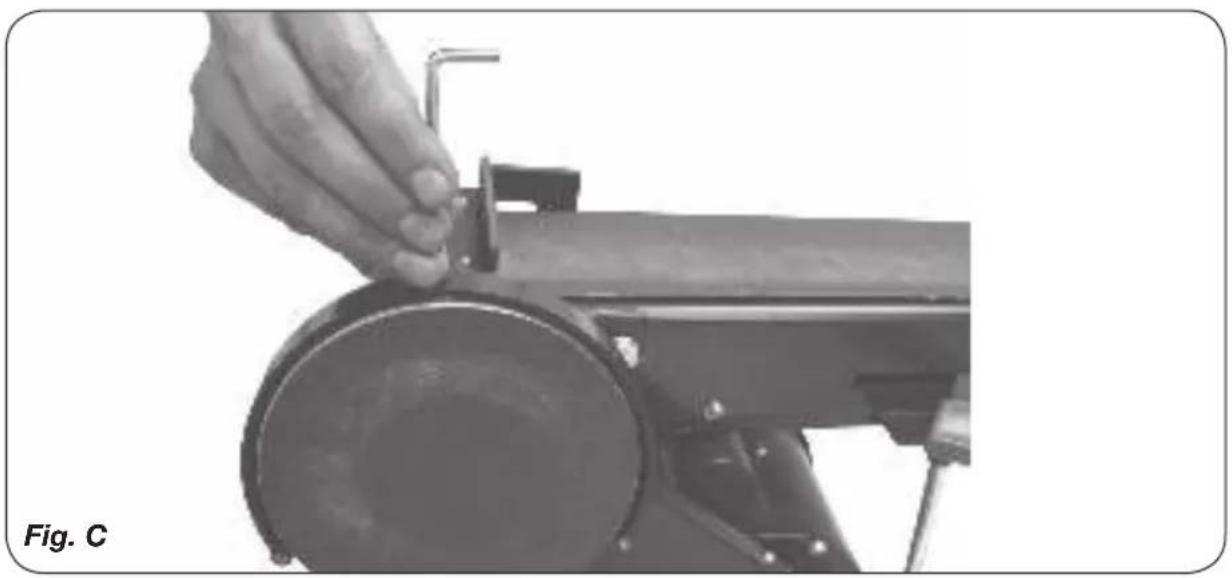
natural_image
Close-up of a hand operating a sewing machine with a circular component, labeled 'Fig. C' in the corner (no other text or symbols visible)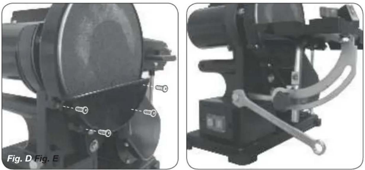
natural_image
Two mechanical assembly diagrams labeled Fig. D and Fig. E, showing components like gears and linkages (no text or symbols on the devices themselves)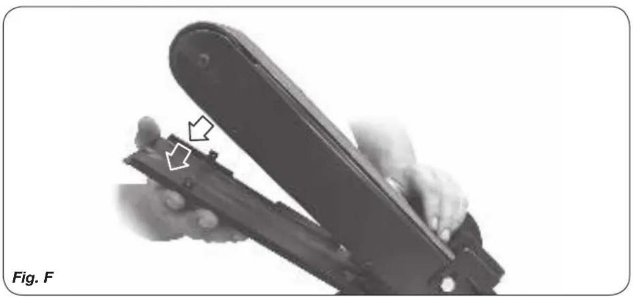
natural_image
Close-up of a hand holding a mechanical device with a tool, showing a close-up of the component (no text or symbols visible)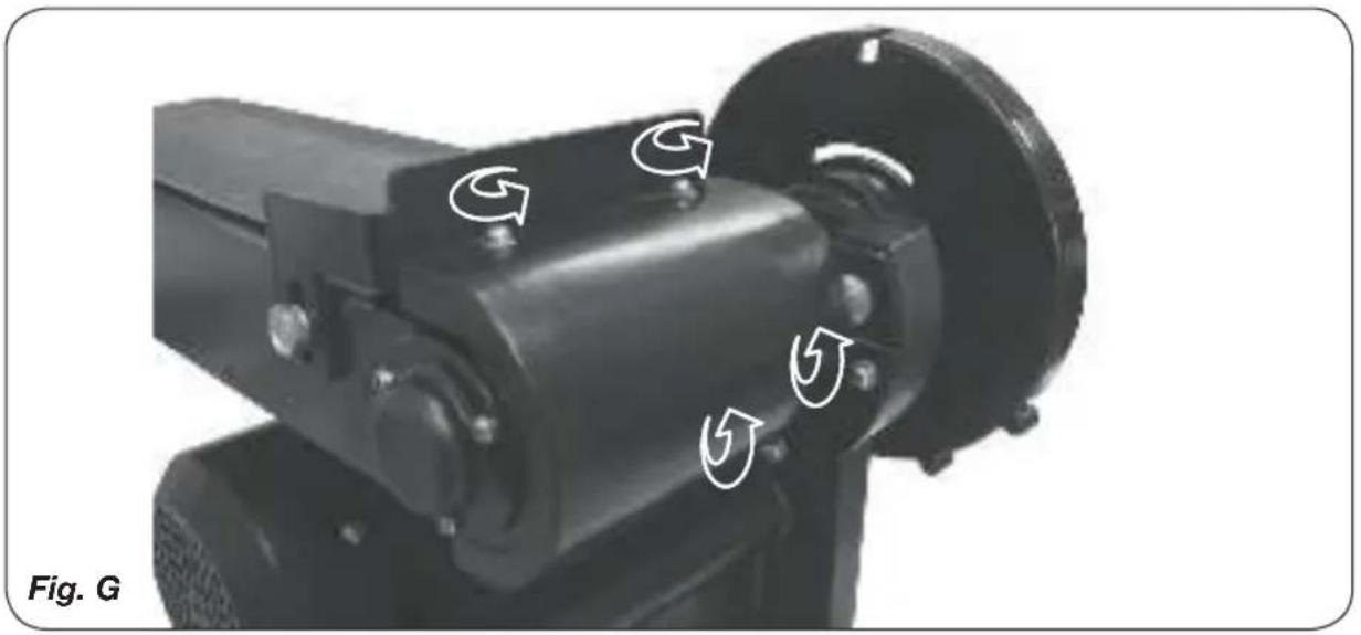
natural_image
Close-up of a mechanical device with directional arrows indicating motion or rotation (no text or symbols on the device itself)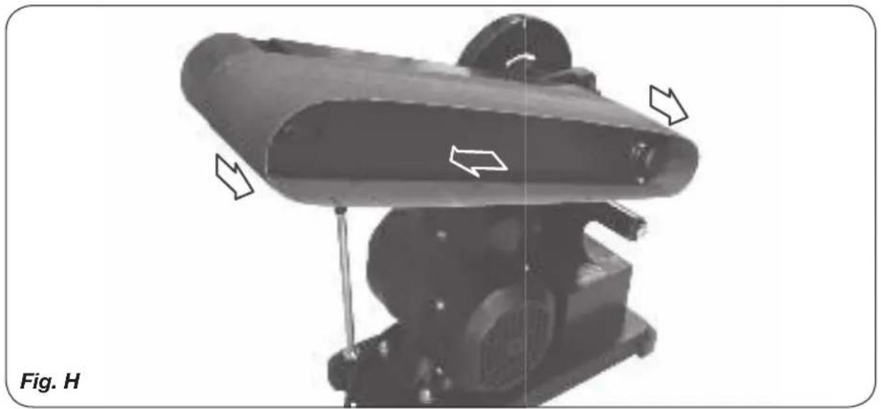
natural_image
Mechanical device with directional arrows indicating motion or flow, labeled Fig. H (no text or symbols on the device itself)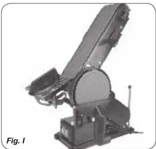
natural_image
Mechanical robotic arm device labeled Fig. I, showing articulated arms and base mount (no text or symbols on the device itself)BENCH SANDER
BGM1022 350W
Thank you for buying this FERM product. By doing so you now have an excellent product, delivered by one of Europe's leading suppliers. All products delivered to you by Ferm are manufactured according to the highest standards of performance and safety. As part of our philosophy we also provide an excellent customer service, backed by our comprehensive warranty. We hope you will enjoy using this product for many years to come.
1. SAFETY INSTRUCTIONS

Read the enclosed safety warnings, the additional safety warnings and the instructions. Failure to follow the safety warnings and the instructions may result in electric shock, fire and/or serious injury. Save the safety warnings and the instructions for future reference.
The following symbols are used in the user manual or on the product:

Denotes risk of personal injury, loss of life or damage to the tool in case of non-observance of the instructions in this manual.

Indicates electrical shock hazard.
Keep bystanders away

Wear ear and eye protection

Wear a dustmask

The product is in accordance with the applicable safety standards in the European directives.
Special safety instructions
- The following points need to be checked:
- Do the connecting voltage of the machine correspond with the mains voltage.
- Are the mains lead and the mains plug in a good condition; strong, without ravels or damages.
- For functional reasons the turning parts of this machine are not covered. Therefore it is of utmost importance to be careful. Hold the workpiece firmly, to prevent it from slipping from your hands. Never touch the sanding surfaces of a working machine with your hands.
- Avoid the use of long extension cables.
Before you operate the machine:
- Always keep the mains cable away from moving parts of the machine.
- Use safety goggles.
- Use a dust mask.
Electrical safety
When using electric machines always observe the safety regulations applicable in your country to reduce the risk of fire, electric shock and personal injury. Read the following safety instructions and also the enclosed safety instructions.

Always check that the power supply corresponds to the voltage on the rating plate.
Using extension cables
Only use an approved extension cable suitable for the power input of the machine. The minimum conductor size is 1.5 mm2. When using a cable reel always unwind the reel completely.
Immediately switch off the machine when:
- Excessive sparking of the carbon brushes and verticiliosis in the collector.
- Interruption of the mains plug, mains lead or mains lead damage.
- Defectswitch
- Smoke or stench of scorched isolation
2. MACHINE INFORMATION
Intended use
This machine combines all the advantages of a horizontal and a vertical belt sander with those of a disc sander. Its sturdy construction in cast iron and steel makes the machine suitable for every sanding job.
Technical specifications
Voltage 230-240 V, 50 Hz
Power input 350W
S2= 30 min*
No load speed sander belt 292m/min
No load speed sander disc 1450 /min
Sanding belt size 915 X 100 mm
Sanding disc size ∅ 150 mm
Weight 12.2 kg
Lpa (Sound pressure level) 77+3 dB(A)
Lwa (Sound power level) 90+3 dB(A)
^* S2= Maximum period of operation with a capacity of 350 W
Vibration level
The vibration emission level stated in this instruction manual has been measured in accordance with a standardised test given in EN 60745; it may be used to compare one tool with another and as a preliminary assessment of exposure to vibration when using the tool for the applications mentioned
- using the tool for different applications, or with different or poorly maintained accessories, may significantly increase the exposure level
- the times when the tool is switched off or when it is running but not actually doing the job, may significantly reduce the exposure level
Protect yourself against the effects of vibration by maintaining the tool and its accessories, keeping your hands warm, and organizing your work patterns
Description
The numbers in the text refer to the diagrams on pages 2-5.
-
Machine frame
-
Motor
-
Roller stop and parallel stop
-
Clamping handle
-
Transport roller
-
Sanding belt
7 On/off switch
-
Fence
-
Drive roller
-
Aluminium disc
- Sanding disc
- Working table
- Mitre scale
- Supporting arm
- Connection vacuum cleaner
3.ASEMBLY
Installation
Avoid the use of long extension cables. Do not forget to leave enough space around the machine for the workpieces to be sanded.
Assembly
- Put the machine frame on its head and press the four rubber stops into the foot of the frame.
- Machine frame, aluminium disc (10) and work plate (12) are supplied in separate packaging.
- Push the aluminium disc on the shaft and fasten the disc with the socket bolt in the side of the disc (Fig.B - D).
- Place the work plate (12) with the shaft in the machine frame and secure the work plate with the bolt in the side of the machine frame. Check with a 90° sash angle on the work plate and against the sanding disc if the angle is exactly 90° (Fig.E).
- If necessary, adjust this angle with the calibration indicator.
- The mitre scale (13), which is also supplied separately, can be placed on the work plate (12). With the use of this mitre scale the angle of grinding can be determined precisely.
- The fence (8) for the belt sander can be placed behind the uppermost bolt of the V-belt guard. In this way the workpiece can be held firmly against the belt, without great hazards.
- Attach the vacuum cleaner to the vacuum cleaner connections (15)

To prevent the workpiece or your fingers from getting caught between the work plate (12) and the sanding disc (11), the space between work plate (12) and sanding disc (11) must not exceed 1.6 mm.
The choice of sanding paper
With coarse sanding paper (P 60) generally most of the material can be removed, and fine sanding paper (P 150) is then used for finishing. An uneven surface is first treated with coarse sanding paper and sanded until it is even. Subsequently medium-coarse sanding paper (P 100) is used to remove the scratches caused by the first type of paper used. Fine sanding paper (P 150) is used for finishing. The sanding needs to be continued until the surface is smooth.
The placing of the sanding paper
Fig. F - H
When the sanding machine is held with the sanding disc turned towards you, the sanding belt moves from right to left along the upper part of the machine. Because of this turning direction the workpiece will be pressed against the right side of the fence. An arrow on the inside indicates the right direction of running of the sanding belt (see drawing). If no direction is indicated, the sanding belt must be placed in such a way that the elevated part of the seam is placed into the turning direction of the belt. So it is very important that the sanding belt is placed in the correct way. The machine uses standard 100 x 915 mm sanding belts (6):
- Remove the plug from the mains socket.
- Push the clamping handle completely to the right to take away the tension of the transport rollers (4).
- Push the sanding belt along both of the transport rollers, starting from the back of the machine.
- Push the clamping handle completely to the left. Now the sanding belt should be completely tight.
- Turn the transport roller exactly in a right angle to the direction of the sanding belts with the use of the winged nut at the right roller. The direction of running of the belt is adjusted correctly if the sides of the sanding belt are running parallel to the bearing plate.
The sanding disc
Fig. D
Paper or "velcro" plates are used for the sanding disc. The standard diameter is 150 mm. The plates are self adhesive.
Vertical placing of the sanding belt
Fig. I
For more flexibility of the sanding belt its bottom side can be used, because there is no bearing plate. For an easy reach of this bottom side the sanding belt can be placed in vertical position.
- Loosen the two nuts at the front of the sanding machine, around the left transport roller shaft, with the use of an open-end spanner.
- Push the sanding belt up in the position desired.
- Fasten the two nuts again.
- The workpiece can now rest on the worktop instead of on the sanding belt;
- The work plate which is used for the sanding disc can now be pushed with the shaft into the hole of the machine frame, at the left side of the sanding machine.
- Fasten the bolt at the back of the machine.
- The work plate can now be used as support for the sanding of the work piece against the sanding belt.
4. OPERATION

Always stand facing the machine so that you always have a good overview (Fig. A).
Switching On/Off
- Press the switch into position '1' to put your sanding machine into operation.
- To switch off the machine the same switch needs to be vpressed to position '0'.
- Always keep the mains cable away from moving parts.
- There is no need to apply any pressure with the workpiece, because this only slows down the speed of the sanding disc.
Sanding
The sanding belt and disc supplied with this sanding machine are suitable for the sanding of metal, wood or synthetic surfaces. The workpiece should always be held firmly during sanding. No extra pressure is needed. Guide the work piece up and down over the sanding belt, in order to prevent the sanding belt and plate from wearing through in one place. Round objects can be
sanded at the ends of the sanding belt. Work pieces which are longer than the sanding machine can be sanded by removing the fence.
NB: To prevent splintering, wood always needs to be sanded in the longitudinal direction of the grain.
To treat a very soft surface, there is a very handy method to ‘bring the particles to the surface’. This is done as follows: wet the already sanded surface with a cloth or sponge and let it dry well. Some wood fibres will swell up more than others, which leads to a rougher surface than before. Now the higher particles are treated with fine sanding paper, the result is a remarkably smooth surface. This method should not be applied with varnished wood, however, because the varnish may come loose because of the moisture.
5. MAINTENANCE

Before cleaning and maintenance, always switch off the machine and remove the mains plug from the mains.
Clean the machine casings regularly with a soft cloth, preferably after each use. Make sure that the ventilation openings are free of dust and dirt. Remove very persistent dirt using a soft cloth moistened with soapsuds. Do not use any solvents such as gasoline, alcohol, ammonia, etc. Chemicals such as these will damage the synthetic components.
Replace power cords
If the supply cord is damaged, it must be replaced by the manufacturer, its service agent or similarly qualified persons in order to avoid a hazard.
Mains plug replacement (UK only)
If the moulded 3-pin plug attached to the unit is damaged and needs replacing, it is important that it is correctly destroyed and replaced by an approved BS 1363/7A fused plug and that the following wiring instructions are followed. The wires in the mains cable are coloured in accordance with the following code:
- blueneutral
•brownlive
As the colours of the wires in the mains cable of the unit may not correspond to the coloured markings identifying the terminals in the plug, proceed as follows:
- The wire which is coloured blue must be connected to the terminal which is marked with the letter N or coloured black.
- The wire which is coloured brown must be connected to the terminal which is marked with the letter L or coloured red.
ENVIRONMENT

Faulty and/or discarded electrical or electronic apparatus have to be collected at the appropriate recycling locations.
Only for EC countries
Do not dispose of power tools into domestic waste. According to the European Guideline 2012/19/EU for Waste Electrical and Electronic Equipment and its implementation into national right, power tools that are no longer usable must be collected separately and disposed of in an environmentally friendly way.
WARRANTY
The warranty conditions can be found on the separately enclosed warranty card.
The product and the user manual are subject to change. Specifications can be changed without further notice.
- Machine frame
- Motor
- Roller stop and parallel stop
- Clamping handle
- Transport roller
- Sanding belt
7 On/off switch - Fence
- Drive roller
- Aluminium disc
- Sanding disc
- Work plate
- Mitre scale
- Supporting arm
- Aansluiting stofzuiger
3. MONTAGE
Installatie
2. INFORMATIONS RELATIVES LA MACHINE
Utilisation prévue
Vertical placing of the sanding belt
Obr. I
CE
DECLARATION OF CONFORMITY BGM1022 - BELT AND DISC SANDER
(EN) We declare under our sole responsibility that this product is in conformity with directive 2011/65/EU of the European parliament and of the council of 8 June on the restriction of the use of certain hazardous substances in electrical and electronic equipment is in conformity and accordance with the following standards and regulations:
(DE) Der Hersteller erklärt eigenverantwortlich, dass dieses Produkt der Direktive 2011/65/EU des Europäischen Parlaments und des Rats vom 8. Juni 2011 über die Einschränkung der Anwendung von bestimmten gefährlichen Stoffen in elektrischen und elektronischen Geräten entspricht. den folgenden Standards und Vorschriften entspricht:
(NL) Wij verklaren onder onze volledige verantwoordelijkheid dat dit product voldoet aan de conform Richtlijn 2011/65/EU van het Europees Parlement en de Raad van 8 juni 2011 betreffende beperking van het gebruik van bepaalde gevaartlijke stoffen in elektrische en elektronische apparatuur en in overeenstem ming is met de volgende standaarden en reguleringen:
(FR) Nous déclarons sous notre seule responsabilité que ce produit est conforme aux standards et directives suivants: est conforme à la Directive 2011/65/EU du Parlement Européen et du Conseil du 8 juin 2011 concernant la limitation d'usage de certaines substances dangereuses dans l'équipement électrique et électronique.
(ES) Declaramos bajo nuestra exclusiva responsabilidad que este producto cumple con las siguientes normas y estándares de funcionamiento: se encuentra conforme con la Directiva 2011/65/UE del Parlamento Europeo y del Consejo de 8 de junio de 2011 sobre la restricción del uso de determinadas sustancias peligrosas en los equipos eléctricos y electrónicos.
(PT) Declaramos por nossa total responsabilidade de que este produto está em conformidade e cumpre as normas e regulamentações que se seguem: está em conformidade com a Directiva 2011/65/EU do Parlamento Europeu e com o Conselho de 8 de Junho de 2011 no que respeita à restrição de utilização de determinadas substâncias perigosas existentes em equipamento eléctrico e electrónico.
(IT) Dichiariamo, sotto la nostra responsabilità, che questo prodotto è conforme alle normative e ai regolamenti seguenti: è conforme alla Direttiva 2011/65/UE del Parlamento Europeo e del Consiglio dell'8 giugno 2011 sulla limitazione dell'uso di determinate sostanze pericolose nelle apparecchiature elettriche ed elettroniche.
(SV) Vi garanterar på eget ansvar att denna produkt uppfyller och följer följande standarder och bestämmelser: uppfyller direktiv 2011/65/EU från Europeiska parlamentet och EG-rådet från den 8 juni 2011 om begränsningen av användning av farliga substanser i elektrisk och elektronisk utrustning.
(FI) Vakuutamme yksinomaan omalla vastuullamme, että tämä tuote täyttää seuraavat standardit ja säädökset: täyttää Euroopan parlamentin ja neuvoston 8. kesäkuuta 2011 päivätyn direktiivin 2011/65/EU vaatimukset koskien vaarallisten aineiden käytön rajoitusta sähkö- ja elektronisissa laitteissa.
(NO) Vi erklærer under vårt eget ansvar at dette produktet er i samsvar med følgende standarder og regler: er i samsvar med EU-direktivet 2011/65/EU fra Europa-parlamentet og Europa-rådet, pr. 8 juni 2011, om begrensning i bruken av visse farlige stoffer i elektrisk og elektronisk utstyr.
(DA) Vi erklærer under eget ansvar, at dette produkt er i overensstemmelse med følgende standarder og bestemmelser: er i overensstemmelse med direktiv 2011/65/EU fra Europa-Parlamentet og Rådet af 8. juni 2011 om begrænsning af anvendelsen af visse farlige stoffer i elektrisk og elektronisk udstyr.
(HU) Felelősségünk teljes tudatában kijelentjük, hogy ez a termék teljes mértékben megfelelazalábbiszabványoknakésselőlásoknakjevsouladusesměmicí 2011/65/EUEvropskéhoparlamentuaRadyEUzedne8.června2011,kterásetýká omezenípoužitíurčitýchnebezpečnýchlátekvelektrickýchaelektronických zařízeních.
(CS) Na naši vlastní zodpovědnost prohlašujeme, že je tento výrobek v souladu s následujícímistandardyanormami: Jevsúladesnormou 2011/65/EÜEurópskeho parlamentuaRadyz8.júna2011týkajúcejsaobmedzeniapoužívaniaurčitých nebezpečnýchlatokvelektrickomaelektronickomvybavení.
(SK) Výhlasujeme na našu výhradnú zodpovednosť, že tento výrobok je v zhode a súlade snasledujúciminormamiapredpísmí. Jevsúladesnormou2011/65/EÚÉurópske hoparlamentuaRadyz,júna2011týkajúcejsaobmedzeniapoužívaniaurčitých nebezpečnýchlatókvelektrickomalelektronickomvybavení.
(SL) S polno odgovornostjo izjavljamo, da je ta izdelek v skladu in da odgovarja naslednjim standardom terpredpisom: je v skladu z direktivo 2011/65/EU Evropskega parlamenta in Sveta z dne 8. junij 2011 o omejevanju uporabe določenih nevarnih snovi v električni in elektronski opremi.
(PL) Deklarujemy na własną odpowiedzialność, że ten produkt spełnia wymogi zawarte w następujących normach i przepisach: jest zgodny z Dyrektywą 2011/65/UE Parlamentu Europejskiego i Rady z dnia 8 czerwca 2011 r. w sprawie ograniczenia stosowania niektórych niebezpiecznych substancji w sprzęcie elektrycznym i elektronicznym.
(LT) Prisiimdami visą atsakomybę deklaruojame, kad šis gaminys atitinka žemiau paminėtusstandartusarbanuostatus:atitinka2011m.birželio8d.Europos ParlamentoirTarybosdirektyva2011/65/EBdėltamtikrupavojingųmedžiagų naudojimoelektrosirelektroninėjejrangojeapribojimo.
(LV) Ir atbilstoša Eiropas Parlamenta un Padomes 2011, gada 8. jūnija Direktīvai 2011/65/ESpardažubīstamuvieluizmantošanasierobežošanuelektriskāsun elektroniskāsiekārtās.
(ET) Apgalvojam ar visu atbildību, ka šis produkts ir saskaņā un atbilst sekojošiem standartiem un nolikumiem: ir atbilstoša Eiropas Parlamenta un Padomes 2011. gada 8. jūnija Direktīvai 2011/65/ES par dažu bīstamu vielu izmantošanas ierobežošanu elektriskās un elektroniskās iekārtās.
(RO) Declarăm prin aceasta cu răspunderea deplină că produsul acesta este în conformitatecuurmătoarelestandaresaudirective: este în conformitatecu Directiva 2011/65/UEaParlamentuluiEuropeansția Consiliuluidin8iunie 2011cu privire la interzicerea utilizării anumitor substanțe periculoase la echipamentele electrice și electronice.
(HR) Izjavljujemo pod vlastitom odgovornošu da je strojem ukladan sa slijedešim standardimali165standardiziranimdkumentimaiuskladusaodredbama:usklađenos Direktivsom2011/65/EUeurospogparlamentaivijećaizdanom8.lipnja2011.o ograničenjukorištenjaodređenihopasnihtrivuelektričnojelektroničkojopremi.
(SRL)Pod punom odgovornošću izjavljujemo da je usaglašen sa sledećim standardima ili normama: usaglašen sa direktivom 2011/65/EU Evropskog parlamenta i Saveta od 8. juna.2011. godine za restrikciju upotrebe određenih opasnih materija u električnoj i elektronskoj opremi.
(RU) Под свою ответственность заявляем, что данное изделие соответствует следующим стандартам и нормам: соответствует требованиям Директивы 2011/65/EU Европейского парламента и совета от 8 июня 2011 г. по ограничению использования определенных опасных веществ в электрическом и электронном оборудовании
(UK) На свою власну відповідальність заявляємо, що дане обладнання відповідає наступним стандартам і нормативам: задовольняє вимоги Директиви 2011/65/ЄС Європейського Парламенту та Ради від 8 червня 2011 року на обмеження використання деяких небезпечних речовин в електричному та електронному обладнанні.
(EL) Δηλώνουμε υπεύθυνα ότι το προϊόν αυτό συμφωνεί και τηρεί τους παρακάτω κανονισμούς και πρότιπα: συμμοφρώνεται με την Οδηγία 2011/65/ΕΕ του Ευρωπαϊκού Κοινοβουλίου και του Συμβουλίου της 8ης Ιουνίου 2011 για τον περιορισμό της χρήσης ορισμένων επικώδυνων υσιών σε ηλεκτρικό και ηλεκτρονικό εξοπλισμό.
(AR) تيذاتلا داميجرتلاو روياعىلما عم قفراوتي جكتجلا اندناً اندح و انشكيلوئەسم ظildع نلالعين
(TR) Tek sorumlusu biz olarak bu ürünün aşağıdaki standart ve yönergelere uygun olduğunu beyan ederiz.
(MK) Изјавуваме со наша цепосна одговорност дека производот е во согласност со Смерницата 2011/65/EU на Европскют парламент и е во согласност според Советот од 9 јуни за ограничување на користење на одредени опасни супстанции во електричната и електронската опрема и дека е според следните стандарди и регулативи:
EN61029-1, EN55014-1, EN55014-2, EN61000-3-2, EN61000-3-3
2006/42/EC, EN12100, 2014/30/EU, 2011/65/EU, 2012/19/EU
Zwolle, 01-01-2018
H.G.FRosberg CEO FERM B.V.
FERM B.V. - Lingenstraat 6 - 8028 PM - Zwolle - The Netherlands


- BGM1022
- BENCH SANDER
- BGM1022 350W
- SAFETY INSTRUCTIONS
- Special safety instructions
- Before you operate the machine:
- Electrical safety
- Using extension cables
- MACHINE INFORMATION
- Intended use
- Technical specifications
- Vibration level
- Description
- 3.ASEMBLY
- Installation
- Assembly
- The choice of sanding paper
- The placing of the sanding paper
- Fig. F - H
- The sanding disc
- Fig. D
- Vertical placing of the sanding belt
- Fig. I
- OPERATION
- Switching On/Off
- Sanding
- MAINTENANCE
- Replace power cords
- Mains plug replacement (UK only)
- ENVIRONMENT
- Only for EC countries
- WARRANTY
- MONTAGE
- Installatie
- INFORMATIONS RELATIVES LA MACHINE
- Utilisation prévue
- Obr. I
- CE
- DECLARATION OF CONFORMITY BGM1022 - BELT AND DISC SANDER
Brand : Ferm
Model : BGM1022
Category : Sander