OF 1400 EBQPLUS - Router FESTOOL - Free user manual and instructions
Find the device manual for free OF 1400 EBQPLUS FESTOOL in PDF.
| Product type | Router |
| Brand | Festool |
| Model | OF 1400 EBQPLUS |
| Power consumption | 1400 W |
| No-load speed | 10,000 - 22,500 rpm |
| Max speed (no-load) | 23,000 min⁻¹ |
| Fast depth adjustment range | 70 mm |
| Micrometric depth adjustment range | 8 mm (0.1 mm per click) |
| Spindle connection thread | M22x1.0 |
| Max. cutter diameter | 63 mm |
| Weight (according to EPTA 01:2014) | 4.4 kg |
| Protection class | II (double insulation) |
| Sound pressure level | LPA = 95 dB(A) |
| Sound power level | LWA = 106 dB(A) |
| Vibration emission value (ah) | < 2.5 m/s² |
| Electronic brake | Yes (stop in ~2 s) |
| Safety functions | Restart protection, thermal fuse, spindle lock |
| Power supply | Mains (Plug-it cable) |
| Voltage and frequency | See rating plate (e.g. 230 V / 50 Hz) |
| Dust extraction connection | 27 or 36 mm (antistatic recommended) |
| Spare parts | Available from Festool (carbon brushes, collets, etc.) |
| Repairability | Festool authorized service center |
Frequently Asked Questions - OF 1400 EBQPLUS FESTOOL
User questions about OF 1400 EBQPLUS FESTOOL
0 question about this device. Answer the ones you know or ask your own.
Ask a new question about this device
Download the instructions for your Router in PDF format for free! Find your manual OF 1400 EBQPLUS - FESTOOL and take your electronic device back in hand. On this page are published all the documents necessary for the use of your device. OF 1400 EBQPLUS by FESTOOL.
USER MANUAL OF 1400 EBQPLUS FESTOOL
OF 1400 EQ OF 1400 EBQ
Festool GmbH
Wertstraße 20
73240 Wendlingen
Germany
+49 (0)70 24/804-0
www.festool.com
Declaration of Conformity
We as the manufacturer Festool GmbH, Wertstraße 20, 73240 Wendlingen, Germany declare under our sole responsibility that the product(s):
Designation:
Router
Designation of Type[s]:
OF 1400 EBQ; OF 1400 EQ
Serial number(s) 1):
10464480, 10464484
fulfills all the relevant provisions of the following UK Regulations:
S.I. 2008/1597
Supply of Machinery (Safety) Regulations 2008
S.I. 2016/1091
Electromagnetic Compatibility Regulations 2016
S.I. 2012/3032
Restriction of the Use of Certain Hazardous Substances in Electrical and Electronic Equipment Regulations 2012
and are manufactured in accordance with the following designated standards:
BS EN 62841-1:2015
BSEN62841-2-17:2017
BSEN55014-1:2017
BSEN55014-2:2015
BS EN IEC 61000-3-2:2019
BS EN 61000-3-3:2013
BS EN IEC 63000:2018
11 in the specified serial number range (S-Nr.) from 40000000 - 49999999

Place and date of declaration: Wendlingen, 22.07.2021
Signed on behalf of and in name of Festool GmbH
Markus Stark
Head of Product development
i.v. Q Baumann
Ralf Brandt
Head of Productconformity
Oberprüse
Router
Défoncuse
Seriennummer*
Serial number *
N° de série *
(T-Nr.)
OF 1400 EBQ 10464480
OF 1400 EQ 10464484
de EU-Konformitätserklarung. Wir erklären in alleiniger Verantwortung, dass这点es Produkt mit allen relevanten Anforderungen folgender EU-Richtlinien übereinstimmt, und folgende Normen oder normative Dokumente zugrunde gelegt wurden:
en EU Declaration of Conformity. We declare under sole responsibility that this product complies with all the relevant requirements in the following EU Directives, and following standards and normative documents were applied:
fr Déclaration de conformité de l'UE. Nous déclarons, sous notre seule responsabilité, que ce produit satisfait à toutes les exigences pertinentes des directives UE suivantes et repose sur les normes ou documents normatifs suivants:
es Declaracion UE de conformidad. Declaramos bajo esta responsabilidad que este producto cumple todos los requisitos relevantes de las siguientes directivas de la UE y que se han toado como base lassiguidentes normas o documents normativos:
it Dichiarazione di conformità UE. Dichiariamo molto nella sua responsabilità che il presente prodotto sa conformsme a tutti i requisiti di rilevanza definite nelle seguenti Direttive UE e che siano stati applicati le seguenti norme o i seguenti documenti normativi:
nl EU-conformiteitsverklaring. Wij verklaren en stellen ons ervoor verantwoordelijk dat dit product volledig voldoet aan alle volgende EU-richtlijnen en volgende normen of normatieve documenten daaraan ten grondlag gelegd werden:
SV EU-forsakran om overensstammelse. Vi forklarar pa eget ansvar attenna produkt uppfyller alla relevanta krav enligt foljande EU-direktiv och baseras pa foljande normer erler normgivande dokument:
fi EU-vaatimustemmukaisuusvakuutus. Vakuutamme yksinomaisella vastuulla, etta tamä tuote tayttäa seuraavien EU-direktiivien kaikki olennaiset vaatumukset ja se on seuraavien standardien tai standardiasi-kirjojen mukainen:
da EU-overensstemmelseserklaring. Vi erklærer med eneansvar, at dette produit er i overensstemmelse med alle relevante krav i falgende EU-direktiver, og at falgende standarder eller normative dokumenter davon grundlag for det:
nb EU-samsvarserklaering. Vi erklærer under eneansvar at dette produktet oppfyller alle relevante kravifolgende EU-direktiver og at ffolgende standarder ullormative dokumenter er blitt lagt til grunn:
pt Declaração de conformidade UE. Sob{nossa inteira responsabilité,declar Ramos que este produits está de acordo com todas as exigências relevantes das seguides direitivas UE, tendo sido tomadas por base as seguides normas ou documents normativos:
ru Deklapauia o cooTBeCTBn EC. Mblco BcE OTBetCTBeHHocTbIO 3aBnIeM, yTO DaHna IpoDyKUN COOTBeTCTBye T BcEM PpIMeHmblt Tpe6oBaHnM CneDyUOxN DnpeKTnB EC, cTaHdApTOB n HopMaTNBhIx DOkymeHTOB:
CS Prohlasei o shode EU. Prohlasejeme s veske- rou odpovednosti, ze tento vyrobek splnuje vsechny prisluanse pozadavky nasledujicich smernic EU a ze byly pouzity nasledujici normy nebo normativni dokumenty:
pl Deklaracja zgodnosci UE. Niniejszym oswiadczamy na wtasna odpowiedzialnosc, ze produkt ten spenetnia wzystkie obowiazujuce wymogi nastepujacydreyktyw UE, norm lub Dokumentów normatywnych.
2006/42/EC, 2014/30/EU, 2011/65/EU
EN 62841-1: 2015 + AC: 2015, EN 62841-2-17: 2017, EN 55014-1: 2017, EN 55014-2: 2015,
ENIEC61000-3-2:2019,EN61000-3-3:2013
ENIEC 63000:2018

Signed on behalf of and in name of/
Head of Product Development

Ralf Brandt
Head of Product Conformity
1 Symbols. 15
2 Safety warnings. 15
3 Intended use 16
4 Technical data. 16
5 Parts of the device. 16
6 Commissioning. 17
7 Settings. 17
8 Working with the electric power tool. 19
9 Service and maintenance. 20
10 Accessories 21
11 Environment 21
12 General information. 21
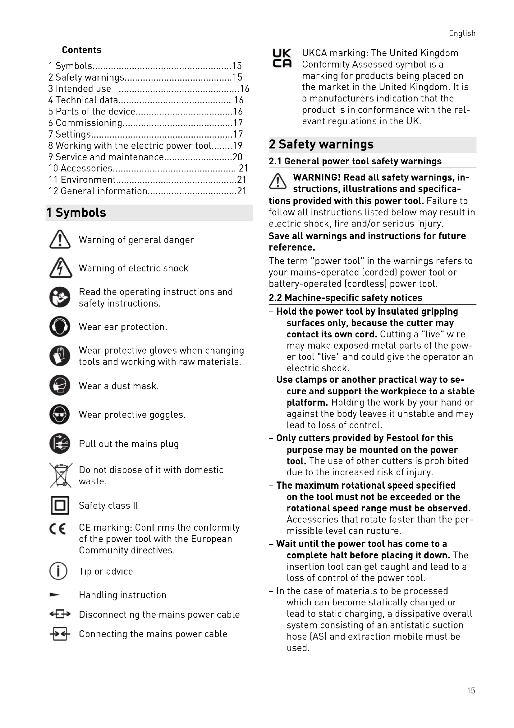
1 Symbols

Warning of general danger

Warning of electric shock

Read the operating instructions and safety instructions.

Wear ear protection.

Wear protective gloves when changing tools and working with raw materials.

Wear a dust mask.

Wear protective goggles.

Pull out the mains plug.

Do not dispose of it with domestic waste.

Safety class II

CE marking: Confirms the conformity of the power tool with the European Community directives.

Tip or advice

Handling instruction

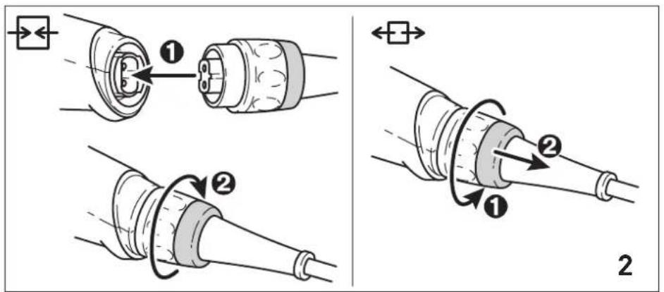
Disconnecting the mains power cable

Connecting the mains power cable

UKCA marking: The United Kingdom Conformity Assessed symbol is a marking for products being placed on the market in the United Kingdom. It is a manufacturers indication that the product is in conformance with the relevant regulations in the UK.
2 Safety warnings
2.1 General power tool safety warnings

WARNING! Read all safety warnings, instructions, illustrations and specifica
tions provided with this power tool. Failure to follow all instructions listed below may result in electric shock, fire and/or serious injury.
Save all warnings and instructions for future reference.
The term "power tool" in the warnings refers to your mains-operated (corded) power tool or battery-operated (cordless) power tool.
2.2 Machine-specific safety notices
- Hold the power tool by insulated gripping surfaces only, because the cutter may contact its own cord. Cutting a "live" wire may make exposed metal parts of the power tool "live" and could give the operator an electric shock.
- Use clamps or another practical way to secure and support the workpiece to a stable platform. Holding the work by your hand or against the body leaves it unstable and may lead to loss of control.
- Only cutters provided by Festool for this purpose may be mounted on the power tool. The use of other cutters is prohibited due to the increased risk of injury.
- The maximum rotational speed specified on the tool must not be exceeded or the rotational speed range must be observed. Accessories that rotate faster than the permissible level can rupture.
- Wait until the power tool has come to a complete halt before placing it down. The insertion tool can get caught and lead to a loss of control of the power tool.
- In the case of materials to be processed which can become statically charged or lead to static charging, a dissipative overall system consisting of an antistatic suction hose (AS) and extraction mobile must be used.
English
- Do not clamp tools with an unsuitable shank diameter in the clamping collet.
- Only use tools that meet standard EN 847-1. All Festool routing tools fulfill these requirements.
- Ensure that the router bit is seated firmly and that it runs perfectly.
- The clamping collet and locking nut must not show any signs of damage
- Do not use cracked or deformed router bits.

Wear suitable personal protective equipment: Ear protection, protective goggles, dust mask for work that generates dust, protective gloves for working with rough materials and for changing tools.
- Only for AS/NZS: The tool shall always be supplied via residual current device with a rated residual current of 30mA or less.
2.3 Sawing aluminium
When sawing aluminium, the following measures must be taken for safety reasons:
- Install an upstream residual-current circuit breaker (RCD, PRCD).
- Connect the power tool to a suitable dust extractor with an antistatic suction hose.
- Regularly clean dust deposits from the motor housing on the power tool.

- Wear protective goggles.
2.4 Emission levels
The levels determined in accordance with EN 62841 are typically:
Sound pressure level L
$$ \mathrm {P A} = 9 5 \mathrm {d B} (\mathrm {A}) $$
Sound power level L
$$ \mathrm {w} _ {\mathrm {A}} = 1 0 6 \mathrm {d B} (\mathrm {A}) $$
Uncertainty K = 3
dB

CAUTION
Noise generated when working Risk of damage to hearing
Use ear protection.
Vibration emission level a_h (vector sum for three directions) and uncertainty K measured in accordance with EN 62841:
$$ a _ {h} < 2. 5 \mathrm {m} / \mathrm {s} ^ {2} $$
$$ K = 1. 5 \mathrm {m} / \mathrm {s} ^ {2} $$
The specified emission levels (vibration, noise)
- are used to compare machines.
- They are also used for making preliminary estimates regarding vibration and noise load during operation.
- They represent the primary applications of the power tool.

CAUTION
The emission values may deviate from the specified values. This is dependent on how the tool is used and the type of workpiece being machined.
The actual load during the entire operating cycle must be evaluated.
Depending on the actual load, suitable protective measures must be defined in order to protect the operator.
3 Intended use
The router is designed for routing wood, plastics and wood-based materials.
If the cutters are used for the intended purpose outlined in the Festool Sales, they may also be used to machine aluminium and plasterboard.
This power tool may only be used by experts or instructed persons.

The user is liable for improper or non-intended use.
4 Technical data
Router OF 1400 EBQ
OF 1400 EQ
Power consumption 1400 W
Speed 10,000-22,500 rpm
Max. speed (no-load) 23,000 rpm
Quick depth adjustment 70 mm
Fine depth adjustment 8 mm
Drive shaft connecting thread
M22×1.0
cutter diameter Max. 63 mm
Weight as per EPTA procedure 01:2014:
4.4 kg
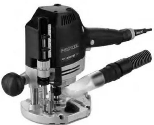
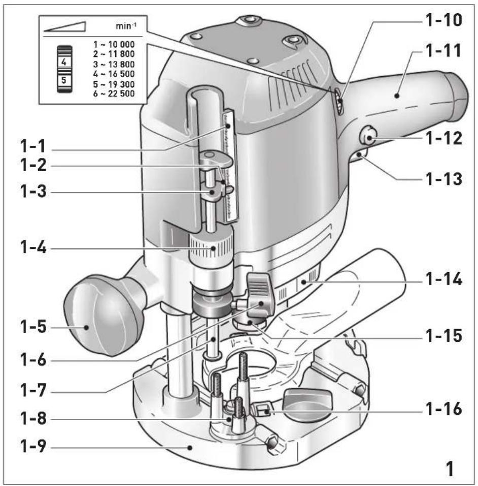
5 Parts of the device
[1-1] Depth stop scale
[1-2] Indicator screw
[1-3] Depth stop indicator
[1-4] Routing depth fine adjustment
[1-5] Handle/Height adjustment
[1-6] Depth stop clamp lever
[1-7] depth stop
[1-8] Stepped stop
[1-9] Routertable
[1-10] Speed adjusting wheel
[1-11] Handle
[1-12] On/off switch locking button
[1-13] On/off switch
[1-14] Spindle stop
[1-15] Nut
[1-16] Button for releasing the copying ring
The specified illustrations appear at the beginning of the Operating Instructions.
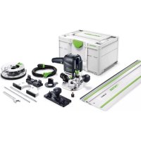
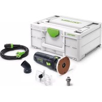
Accessories shown or described are not always included in the scope of delivery.
6 Commissioning

WARNING
Unauthorised voltage or frequency. Risk of accidents
The mains voltage and the frequency of the power source must correspond to the specifications on the name plate.
In North America, only Festool machines with the voltage specifications 120V / 60Hz may be used.

CAUTION
Heating of the Plug it connection if bayonet fitting is not completely locked
Risk of burns
Before switching on the power tool, make sure that the bayonet fitting at the mains cable is closed fully and locked.
Connect and disconnect the mains power cable - [2].
6.1 Switching on/off
The switch [1-13] is an on/off switch (press = ON, release = OFF).
The on/off switch with the locking button [1-12] can be engaged to operate in continuous mode.
Press the on/off switch again to release the lock.
7 Settings

WARNING
Risk of injury, electric shock
Always disconnect the mains plug from the socket before performing any work on the machine.
7.1 Electronics
Speed control
You can continuously adjust the speed within the speed range using the adjusting wheel [1-10] (see "Technical data").
This enables you to optimise the cutting speed to suit the respective material.
Material Cutter diameter (mm) Recom
10-25 25-40 40-60
mended
Adjusting wheel setting
cutting ma
terial
Hardwood 6-4 5-3 3-1 HW (HSS)
Soft wood 6-5 6-3 4-1 HSS [HW]
Coated 6-5 6-3 4-2 HW
chipboard
Plastic 6-4 5-3 2-1 HW
Alumni- 3-12-1 HSS (HW)
um
Plaster- 2-11 HW board
Temperature cut-out
The power supply is restricted and the speed reduced if the motor exceeds a certain temperature. The power tool continues operating at reduced power to allow the ventilator to cool the motor quickly. The power tool starts up again automatically once the motor has cooled sufficiently.
Restart protection
The built-in restart protection prevents the power tool from starting up again automatically if the power is disconnected when the on/off switch is pressed. In this case, the power tool must be switched off and then switched back on again.
Due to the built-in restart protection, the power tool cannot be switched on and off via an external switch module.
English
Brake
The OF 1400 EBQ has an electronic brake which brings the spindle with tool to a standstill within approx. 2 seconds of the tool being switched off.
7.2 Changing tools


CAUTION
Risk of injury from hot and sharp insertion tool
- Do not use any blunt or faulty insertion tools.
Wear protective gloves when handling an insertion tool.
To change tools, turn the power tool upside down.
Inserting the tool
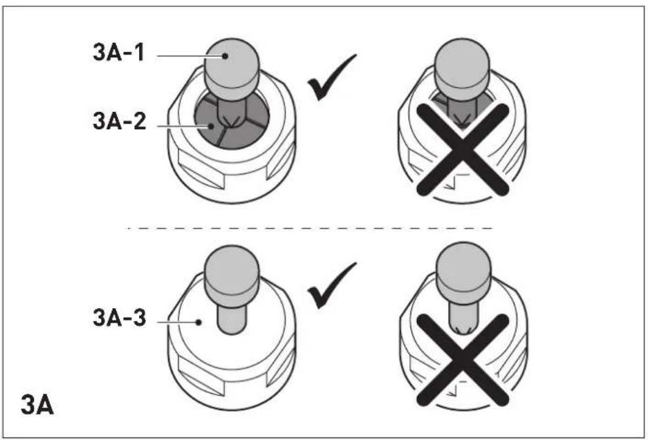
- Insert the routing tool into the open collet as far as possible or at least up to the mark on the router shank.
i If the collet [3A-2] cannot be seen due to the union nut [3A-3], the routing tool [3A-1] must be inserted into the collet to the extent that the mark no longer projects beyond the union nut.
Press the switch [1-14] for the spindle stop on the right-hand side.
- Tighten the nut [1-15] using an open ended spanner (WAF 24).
The spindle stop only jams the motor spindle in one direction of rotation. Therefore, there is no need to use a spanner for tightening and loosening nuts. Instead, a ratchet can be moved backwards and forwards.
Removing the tool
Press the switch [1-14] for the spindle stop on the left-hand side.
- Undo the nut [1-15] using an open ended spanner (WAF 24) until you can feel resistance. Overcome the resistance by continuing to turn the open ended spanner.
- Remove the router.
7.3 Changing the collets
Collets are available for the following shaft diameters: 6.0mm 6.35mm 8.0mm 9.53mm 10.0mm 12.0mm 12.7mm (See Festool catalogue or online at www.festool.com for the order numbers)
-
Completely unscrew the nut [1-15] and remove it together with the collet.
-
Only insert a new collet into the spindle if a nut is fitted and engaged.
Gently screw in the nut. Do not tighten the nut if no cutter is inserted.
7.4 Setting the routing depth
The routing depth is set in three steps:
- Set the zero point, see 7.5.
- Specify the routing depth, see 7.6.
- Clamp the routing depth, see 7.7.
7.5 Setting the zero point
- Release the clamp lever [1-6] so that the depth stop [1-7] can move freely.
Position the router with the router table [1-9] on a level surface. Open the rotary knob [1-5] and push the power tool downwards until the cutter sits on the surface. - Clamp the power tool in this position by closing the rotary knob [1-5].
Press the depth stop [1-7] against one of the three fixed stops of the rotatable stepped stop [1-8].
A screwdriver can be used to individually adjust the height of each fixed stop.
- Push the indicator [1-3] downwards so that it points to 0mm on the scale.
If the zero position is incorrect, this can be corrected using the screw [1-2] on the indicator [1-3].
7.6 Specifying the routing depth
The required routing depth can be specified using either quick depth adjustment or fine depth adjustment.
Quick depth adjustment
Pull the depth stop [1-7] upwards until the indicator [1-3] points to the required routing depth.
- Clamp the depth stop in this position using the clamp lever [1-6].
Fine depth adjustment
- Clamp the depth stop using the clamp lever [1-6].
- Set the required routing depth by turning the adjusting wheel [1-4].
(i) Turning the adjusting wheel by a mark changes the routing depth by 0.1mm . A full rotation changes the routing depth by 1mm . The maximum adjustment range for the adjusting wheel is 8mm .
7.7 Clamping the routing depth
- Open the rotary knob [1-5] and push the power tool down until the depth stop touches the fixed stop.
- Clamp the power tool in this position by closing the rotary knob [1-5].
7.8 Dust extraction

WARNING
Heath hazard posed by dust
Always work with an extractor.
Comply with national regulations.
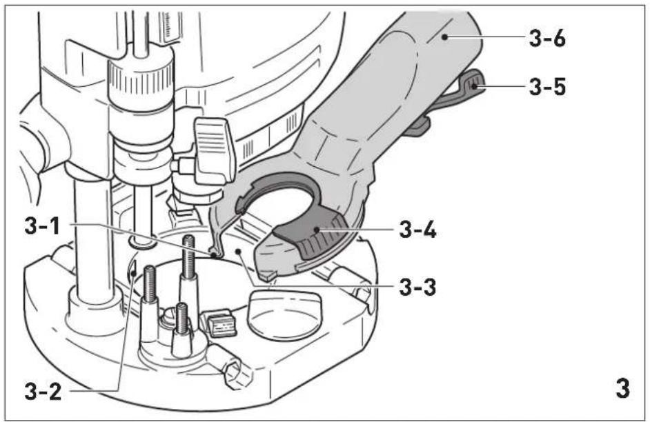
Install the dust extraction attachment on the router table:
Position the dust-extraction attachment with the two tenons [3-1] in the recesses [3-2] on the router table.
Position the dust-extraction attachment on the router table and pull the lever [3-5].
To enable the dust-extraction attachment to be attached and removed when the router is fitted, the cut-out [3-3] in the extractor connector can be opened by turning the segment [3-4].
To ensure optimal dust extraction, the cutout with the rotatable segment must be closed while work is carried out.
A Festool dust extractor with an extractor hose diameter of 36mm or 27mm (36 mm recommended due to the reduced risk of clogging) can be connected to the extractor connector [3-6].
CAUTION! If an anti-static suction hose is not used, static charge may occur. The user may receive an electric shock and the electronics of the power tool may be damaged.
Chip deflector KSF-OF
The chip deflector KSF-OF (available as an accessory depending on the model) can improve the efficiency of the dust extraction system when edge routing.
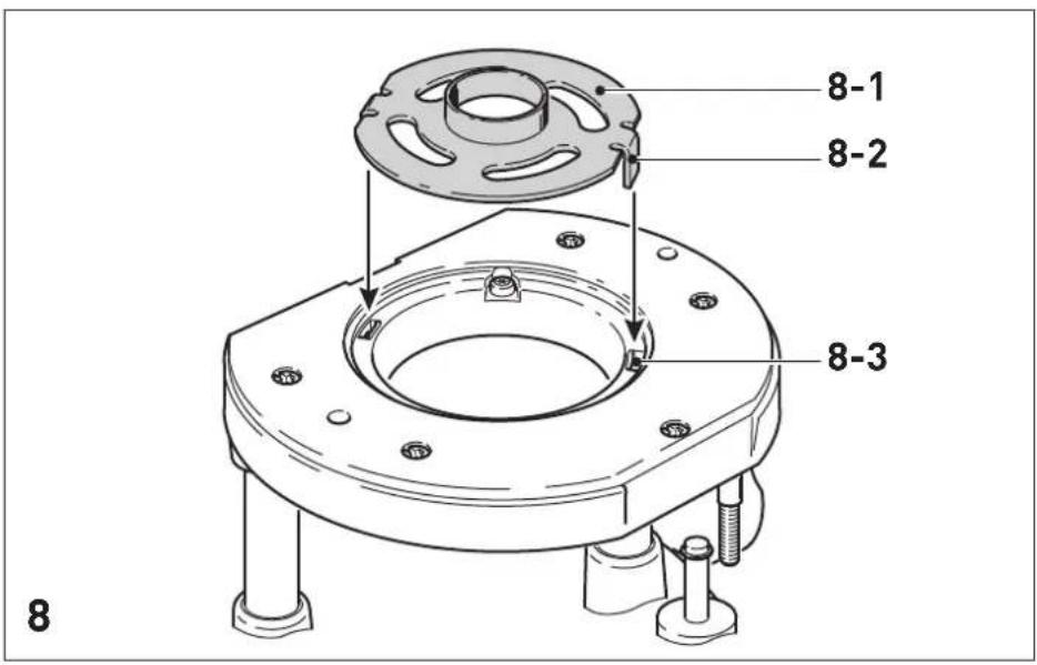
The chip deflector is installed in the same way as the copying ring, see figure [8].
A hacksaw can be used to cut along the grooves of the guard and therefore make it smaller. The chip deflector can then be used for inner radii down to a minimum radius of 40mm
8 Working with the electric power tool
When working on the machine, observe all of the safety warnings that are listed at the start as well as the following rules:
- Only guide the power tool towards the workpiece when it is switched on.
- Always secure the workpiece in such a way that it cannot move during machining.
- When working, always hold the power tool with both hands on the handles [1-5] + [1-11]. This is a prerequisite for precise work and is essential for plunge-cutting. Plunge into the workpiece slowly and evenly.
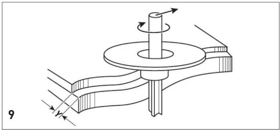
- When routing, ensure that the power tool's feed direction is the same as the tool's cutting direction, see figure [9].
8.1 Freehand routing
Freehand routing is the method normally used for lettering or shapes, and for routing edges using cutters with a guide pin or ring.
8.2 Routing with a parallel side fence
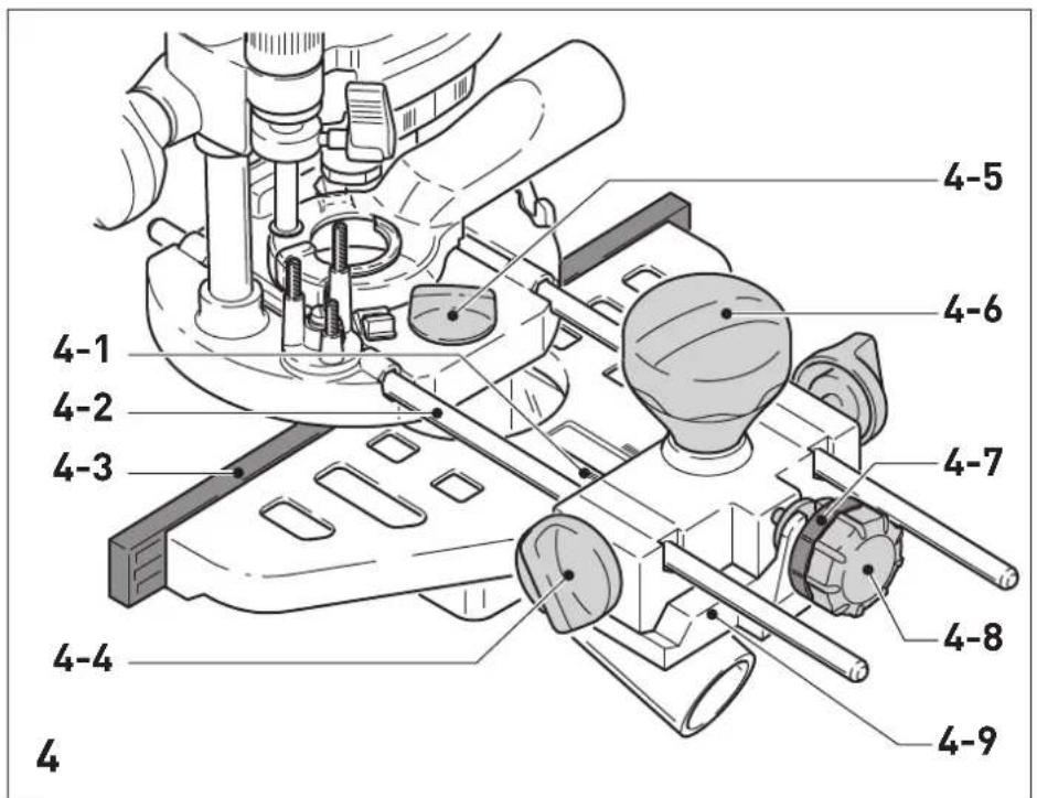
For work running parallel to the workpiece edge, the supplied parallel side fence [4-9] can be used.
- Clamp the two guide rods [4-2] to the parallel side fence using the two rotary knobs [4-4].
- Insert the guide rods into the grooves of the router table to the required extent and clamp them using the rotary knob [4-5].
Fine adjustment
- Open the rotary knob [4-6] to make a fine adjustment using the adjusting wheel [4-8]. The scale ring [4-7] has a 0.1mm scale for this purpose. If the adjusting wheel is held, the scale ring can be turned separately so that it can be set to zero. The scale [4-1] displays the adjustment in millimetres.
- Close the rotary knob [4-6] after making a fine adjustment.
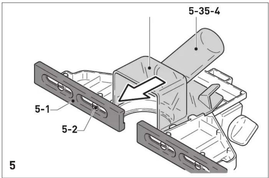
- Set the two guidance jaws [4-3] [5-1] so that they are approx. 5mm from the cutter. To do this, loosen the screws [5-2] and retighten them after making an adjustment.
As shown in figure [5], push the dust-extraction attachment [5-4] from behind until it engages on the parallel side fence.
English
An extractor hose with a diameter of 27mm or 36mm should be connected at the extractor connector [5-3].
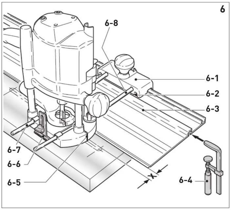
8.3 Routing with the FS guide system
The guide system (available as an accessory) makes it easier to route straight grooves.
- Secure the guide rail adapter [6-1] to the router table using the guide rods [6-8] of the parallel side fence.
- Secure the guide rail [6-3] to the workpiece using fastening clamps [6-4].
Ensure that there is a safety distance X of (see figure [6]) 5 mm between the front edge of the guide rail and the cutter, or the groove.
- Place the guide rail adapter on the guide rail, as shown in figure [6]. To ensure that the router stop can be guided without play, use a screwdriver through the top openings [6-2] on the side to adjust the two guidance jaws.
- Tighten the height-adjustable support [6-6] on the threaded hole of the router table so that the underside of the router table is parallel to the workpiece surface.
When working with marking-up lines, the marks on the platen [6-5] and the scale on the support [6-6] show the centre axis of the cutter.
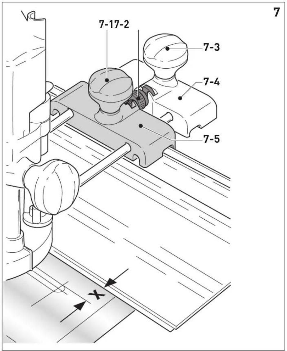
Fine adjuster
The fine adjuster (available as an accessory, [7-5]) can be used to precisely adjust distance X.
Install the fine adjuster [7-5] on the guide rods between the power tool and the guide rail adapter [7-4].
- Insert the adjusting wheel [7-2] into the guide rail adapter, as shown in the figure [7].
Screw the adjusting wheel [7-2] into the nuts of the fine adjuster.
To adjust distance X:
- Open the rotary knob [7-1] for the guide rail adapter and close the rotary knob [7-3] for the fine adjuster.
- Adjust to required distance X by turning the adjusting wheel [7-2].
- Close the rotary knob [7-1] for the guide rail adapter.
8.4 Copy cutting
A copying ring or the copying device is used to exactly reproduce existing workpieces (accessories).
Copying ring
When choosing the size of the copying ring, ensure that the cutter being used fits through its opening.
Excess Y (figure [9]) of the workpiece to the template is calculated as follows:
Y = [copying ring diameter - cutter diameter]/2
- Attach the copying ring [8-1] to the router table: Insert the two tenons [8-2] into the recesses [8-3].
To remove the copying ring: Press the two buttons [1-16] inwards at the same time.
Copying device
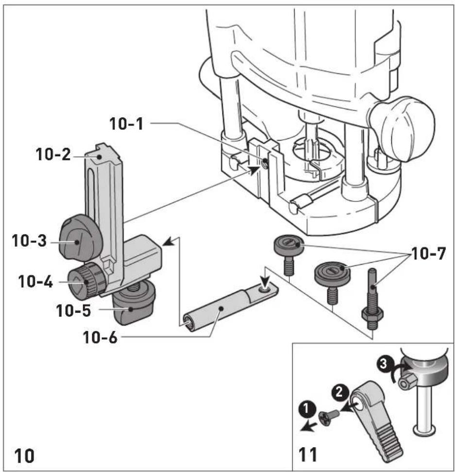
The copying device requires the angle arm WA-OF [10-2] and the copier scanning set KT-OF, consisting of a roller support [10-6] and three copying rollers [10-7].
- Use the rotary knob [10-3] to tighten the angle arm to the required height on the threaded hole [10-1].
Fit a copying roller to the roller support and use the rotary knob [10-5] to tighten it on the angle arm. Make sure that the copying roller and the router have the same diameter.
The distance between the feeler roller and the cutter axis can be adjusted by turning the adjusting wheel [10-4].
9 Service and maintenance


WARNING
Risk of injury, electric shock
Always pull the mains plug from the socket before performing any servicing and maintenance work.
- All maintenance and repair work which requires the housing to be opened should always be carried out by an authorised service workshop.

Customer service and repairs must only be carried out by the manufacturer or service workshops. Find the nearest address at: www.festool.co.uk/service
Always use original Festool spare parts. Order no. at: www.festool.co.uk/service
The tool is equipped with special self-disconnecting carbon brushes. If they wear out, the
power supply is disconnected automatically and the tool stops.
Observe the following instructions:
- Damaged safety devices and components must be repaired or replaced in a recognised specialist workshop, unless otherwise indicated in the operating instructions.
To ensure constant air circulation, always keep the cooling air openings in the housing clean and free of blockages.
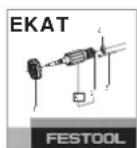
To change the position of the clamp lever [11]
Undo the screw.
- Remove the clamp lever and tighten the hexagon screw.
Put the clamp lever back into the required position and secure it with a screw.
10 Accessories
Always use original Festool tools and accesso
ries. Using low-quality tools or accessories from other manufacturers may increase the risk of injury and seriously unbalance the machine, decreasing the quality of the working results and accelerating power tool wear.
Refer to the Festool catalogue for the order numbers of accessories and tools or find them online at www.festool.co.uk.
11 Environment

Do not dispose of the device in the household waste! Recycle devices, accessories and packaging. Observe appli
cable national regulations.
EU only: In accordance with the European Directive on waste electrical and electronic equipment and implementation in national law, used power tools must be collected separately and handed in for environmentally friendly recycling.
Information on REACH: www.festool.com/reach
12 General information
Imported into the UK by
Festool UK Ltd
1 Anglo Saxon Way
Bury St Edmunds
IP30 9XH
Great Britain
Sommaire
Protection anti-redemarrage
Varning for allman risk

Varning for elstotar

Alumni 3-12-11HSS (HW)
Kipsikar- 2-111 HW tonki
Lämpösulake
Dybde-hurtigindstilling
Mykved 6 - 5 6 - 3 4 - 1 HSS [HW]
Sponpla- 6-56-34-2 HW ter, be-lagt
Plast 6-45-32-1 HW
Alumni 3-12-11HSS(HW) um
Gipsplate 2-11 1 HW
Temperatursikring
He BbI6paCbIBaIte BMeCTe C 6bITOBbIMN OTXoJaMn.

Knaac 3aunTbI II

MapknpoBka CE: POnTBePxxJaet cooTBeTCTBnE 3JIeKTPoHnHCTpyMeHTa OCHOBnHbIM Tpe6OBAHNm DnpeKtNB EC.

HCTpyKzna,pekomeHdaun

HCTpyKznaNo nCnOJb3ObaHnIO

OToeUHeHne ceTeBoro Ka6eJra

PoiocoeiHHeHne ceTeBOro Ka6eJra
2Уka3aHЯ NO TexHnKe 6e3ONaChOcTH
2.1 06uhe yka3aHnno TeXnKe 6e3oNaChOCTn dJa 3JIeKTPoHnCtpyMeHTOB

OCTOPOKHO! ПочтITE Bce yka3aHnno noTexHnke 6e3oNaChocTи nHnctpyKuHn.
HeToUHoe c6JIOpIeHne yKa3aHn MoKeT CTAb npuHOn yJaPa 3JIeKTpueckn TOKOM, NoJkapa n/Inn cepBé3HbIX TpaBM.
CoxpaHnTe Bce yKa3aHnNo TexHnKe 6e3- onaChOCTn N HnCTpyKuN dJa CneDyUoJero noIb30BaTeJIa.
NcnoJIb3yEmbI B yka3aHnX NO TexHnke 6e3-ONaCHOCTN TepMH «3JIeKTPoHHCTpyMeHT> OTHOCNTcK CeTEbbIM 3JIeKTPoHHCTpyMeHTam (c ceTeBBIM Ka6eJIeM) n AKKyMyJrTOpHbIM 3JIeKTPoHHCTpyMeHTAm (6e3 ceTeBOrO Ka6eJIa).
2.2 Yka3aHnno TeXnKe 6e3oNaChOCTn npi nIb30BaHnN nHcTpymeHTOM
-06a3aTeNbHO DepeKHTe 3JeKTPoHcTpymENT 3a H3OJIPOBaHHbIe pyKOaTKN, T. K.Φpe3a MoKeT 3aCenNTb Co6CTBeHHbI Ka-6JIb NITAHn. Pn KoTHaKTe C TOKOpPBODЯUIM NpOBoOM MeTaJIINueCKne YacTN INHCTpyMeHtA MOrY T OKa3aTbcr NOD HaPra-JXeHNEM I CTaTb PnUnHOJ NopaxKeHnA 3JeKTPuYeCKM TOKOM.
-Фнксриte 3arotOBky ctpy6unHAMn nI npyrHMn NOxOJUIMN CpeDcTBaMn Ha yctOnuHBO onope. HeIOCTaTOUHO ydejKnBaTb 3arOTOBky OndHoi JINsb pykoB, B 3tOM cnyae 3arotOBka ocTaETcR HeycTouHBO, n Bbl moKeTe NotepaTb KOHTpOJIb NaHd Hei.
- YctaHaBnBaIte Ha MaunHKy Tolbko 3bl, npedlaraeble Festool. PpIMeHne npyrnx 0pe3 n3-3a NOBbiEHHo TpaBMoo-nachocTn 3anpeucho.
-He donyckaIte npeBbIeHnMaKcMmaIb-HoJ uactOtbl BpaueHn Ipe3bl,co6Iou-daIte dnaIa3OH uactOtbl BpaueHn.0c-HaCTka,BpaauoUaIcraC 60JIbWei,yemdo-nyctmO cKOpocTbIO,MoKeT TpeChyTbN pa3-JeTeTbcR B CTOpHObl.
- Ipepe TEm KaK NoJoxNtB NHCTpyMeHT, NOdoXdnte, NOKa BaI DnRatEn PNOHocTbIO OCTaHOBTc. B npOTnBHom cIyue B03-MoXHo 3auePJIeHne BpaUaHOUsxCra DeTa-JeN, YTO npINBeDET K nOtepe KOHTpOJIa NaHnHCTpyMeHTOM.
-Прп образовке MaTeРиаLoB,HaKaПИВaIO- 申x3JIeKTpOcTaTnueckn 3apRД,Heo6xO- DIMO ИСПОЛБ3OBaTb CnCTeMy ChrTnA 3apR-Дa,B KOTOpyIO BXODIaHTNtCTaTnueckN BCaCbIBAUoiuIshlaHr (AS) n nbIeYdaIaIoo- 申n aIInapaT.
-Диametp XBOCTOBUNKa pa6OueRo NHCTpyMeH-TaДOLЖeH COOTBeTCTBOBaTb 3aXIMHOI ZaHRe.
-ИсpoЛьзуЛteТOLьКОТOTиHCTpyMeHT,КOTOp bI coOTBeTCTByeT Tpe6OBaHnM EN 847-1. BCEΦpe3bFestool yOBoNTBOPrOT 3TN M Tpe6OBaHnM. - PpoBepbTe npouHocTb KpeIeHnA φpe3bl NToUHOCTb eE xOda.
-3axmHa aHra n HaKnHna raKa He 0JXhI IMetb IOBpeJdeHn. - HnkOrda He nCnoB3yIte DeΦopMnpoBaH-HbIe Φpe3bl NΦpe3bl co CKoJaMn.

NcnoIb3yIte noDxOJaUne cpeIcTba HnHnBnDaYalbHoJ 3aunTbI: 3aunTHbIe HayuHnK, 3aunTHbIe OUKN, pecnnpaTOp B cnlyuae o6pa3oBaHnI NBIN BO BpeMpa60TbI; 3aunTHbIe nepaATKn npn o6pa6OTke wepoxOBaTbIX MaTePnaIOB n npn CMeHe NnJIbHO- ro nolToHa.
2.3 06pa6oTKa aHOMHHN
Pn pa6oTe c aIIOHMnHnem nO COo6paXeHNaM 6e30napocTn Heo6xoJMo co6JIouaTb CneyUo- une MepbI:
-ПодклюаиусторьоЗацntHOrOOTKluueHnY(Y30).
-ПодклюанTeЭЛeКТрОнHCTpyMeNTК ПОДхОДЯшемпьileудальношему annapaTy c aHTNCTATNueckmШlaHROM.
- PeryjraRho ouHsauTe 3neKtpOnHcTpymeHT oT OTIOXeHN Nbln B Kopnyce DBNrataJIa.

-PaBraIte B3aunTHbIX OOKax!
2.4 YpObHn UyMa
3haueHn, onpeJeIeHHbIe no EN 62841, ka npabNIO coCTaBJIOT:
YpoBHeH 3ByKoBOrO daBne- LpA=95nE(A) Hnra
YpoBHeMbMoUHocTn3Byko- LwA=106D(B(A) BblXKoJIe6aHnI
IorpeuHoctbK=3dE

BHIMAHNE
Uym,Bo3HnKaIoUnn np pa6oTe NobpeKdHeOpraHOB cnyxa
Pa6oTaIeB3aunTHbIXHayuHnKax.
3HaueHne Bn6paun a, no TpE M OcA M (BeKTop-Ha cymMa) n Ko3ΦnUeH NTorpeuHocTn K, onpeJeHHbIe no EN 62841:
$$ a _ {h} < 2. 5 \mathrm {m} / \mathrm {c} ^ {2} $$
$$ K = 1, 5 \mathrm {m} / \mathrm {c} ^ {2} $$
Yka3aHHbIe 3NaueHnrypOBNy Wyma/Bn6paun
-cnykaTДЯсpaBHeHnIHHCTpyMeHTOB;
-MoXHo TaKKe IcNoJIb3OBAtBДЯпpeiBapN-TeIbHOJ OueHKn WymOBOn N Bn6paCnoHHOHarpy3KN BO BpeMa pa60TbI;
- OtpaKaIOT OCHOBhIe 0bIaCTn IpIMHeHnIe 3JIeKTpOuHcTpyMeHTa.

BHIMAHNE
ФаКТиЧЕСКУЕ YPOВИ N BИБРАЦИ MOr-угТ OTKLOHЯТьСЯ OТ ПИВЕДЕHHых 3Дecь 3Ha-чeн. 3To 3aBnCt O T yCNoBи NcPOnIb3OBA-HN HNCTPyMenta N O T O6pa6aTbIbAemoro Ma-TePnana.
Heo6xOIMO OueHHTb WymOBoe BO3deiCTBnE BpeaIbHbIX ycIOBnX 3KcIIpyaTcNInC yUeTOM BCex 3TaNOB nPOn3BOdCTBeHHOrO uNKJa.
- IcxOJa n3 OueHKn WymOBOro Bo3dEiCTBnBpeaIbHbIX ycNoBnX 3KcNpyaTuCN, Heo6xOJIMO npedpHnHmAtb COOTBeTCTByUOnHeMepbl no oxpaHe Tpyda pa60THNKOB.
HnctpymEnT cKoHcTpynpObaH dIy npofoecnoHaJIbHO rnpMeHeHry.
4 TexHnueckne daHHbIe
3aunTa ot nobToPnOro nycKa
BcTpoeHHa 3aunTa OT NOBTOPO rNcKa npedOTBpaaaet NOBTOHbI ABTomuueckn NyCK 3JIeKTPoHnCTpyMeHTa NocLe npepbBaHnna Noda-yn TOka npn HaxaTOM BbIKJIOUaTeJe. B 3tOM cLyuae 3JIeKTPoHnHCTpyMeHT Heo6xOIMo ChaJa BA BbIKJIOUHTb, a 3aTeM CHOBA BKJIOUHTb.
BcTpoeHHa 3aunTa OT nobToPnO rnycka npedOTBpaaaet BKIOUeHne/BbIKIOUeHne 3JeK-TPoINHCTpymeHTaYepe3 BHeuHm MoyIb BKIOUeHn.
TopMo3
OF 1400 EBQ ochaueH 3JIeKtpoHHbIM TOpMo30M. Pocne BbIKIouehnA fpe3epa TOpMo3 ocTaHa-
BnBaetIHHdJIb c pa6OuHm HNCTpyMeHTOM 3a2ceKyHdbI.
7.2 CmeHa pa6oeryo nHcTpymeHa

BHHMAHNE
Onacnoctb TpaBMnpoBaHnCnIbHo HarpBeBAIOUmCra NocTpbIM pa6OuM INHcTpymeHTOM
He nCnoB3yIe 3aTyNnBUnneecn HeNCnpaBhbIe pa6Oue nHCTpyMeHTbl.
Pn pa6ote c nHcTpymeHTOM noJb3yTecb 3aunTHbIMn nepuATkamn.
7.5 YcTaHOBka Ha HyneByIO OTMeTKy
Pa36bIokpyTe 3axmHoi pbiur [1-6], cy06bl orpaHnHTeJI bIy6nHbI [1-7] cBo-6oHNO dBnraJcra.
- NocTaBbTe BepTnKaJIbHbI Φpe3ep onOpHoN nlaactuHO [1-9]Ha poBHOe oCHOBaHne. OcJa6bTe BnHT-6apaWeK [1-5] n OToXMMte 3JeKTpoINHCtpymeHT Bn3 Do KOHTaKTA φpe3bl c onopoN.
3aΦnKcnpyIte 3JIeKtpOnHCTpyMeHT B 3TOM nOJoxKeHH, 3aTaNbB BuHT-6apawek [1-5].
- PnKMMTe orpaHnHTeJIb rIy6uHbI [1-7] K ODHOMy n3 TpEx XkEcTKnx yNOpOB peBOJb-BepHO rO yNopa [1-8].
Bbicota kaxdo ro ynopa perynpyeTcra OTdJIbHo C nOMOsbIO OTBepTKN.
CdBnHbTe yka3aTeIb [1-3] BHN3 Ha OTMeTKy 0 MM Ha shKaJIe.
Ecn yka3aTeIb He BCTaET Ha HnyeByIO OTMeTKy, ero noLoXeHne MoXHo NoKOppeKTHipoBaTb NOBOpOTOM BnHTa [1-2] Ha camom yka3aTeIe [1-3].
7.6 YctaHOBka rIy6nHbI φpe3epoBaHn
HyxHyu rny6nHy φpe3epoBaHnMa moKHO yCTaHOBnTb DBym CnOc6amn: rpy6o nn TocHo n peRyInpOBko.
rpy6a perynipobka
BbIyBaIte orpaHnHTeIb rIy6nHbI [1-7] BBepx, noka yKa3aTeIb [1-3] He octaHOBtCra Ha OTMeTKe HxKHOI rIy6nHbI 0pe3epoBaHnI.
3aΦHKcpyTe orpaHnHTeB 3TOM NOJIO-XeHN C NOMOuBIO 3axmHOro pbua-ra [1-6].
ToHna perynipobKa
3aXMMTe orpaHnUHTeIb Iy6uHbI 3aXIM-HbIM pbIaIarom [1-6].
- YcTaHOBnTe HxKHyI rIy6uHy fpe3epoBaHnna IOBOpOTom peYunpoBOUHO KOJeca [1-4].
i Pn noBopoTe Ha oHy otMeTky rIy6nHa 01 MM. NohnIOBOpT peYIpOBOUHO KoJeca daET 1 MM. MaKcMaJIbHbI dNanA3OHpeRyIpOBKn CoCTabJIeT 8 MM.
i IJRA TOrO yTo6bI BbITaXHoN KOxKx MoXHO 6blIO CHIMaTb N UCTaHaBJIINBaTb, He CHMaYΦpe3y, MOxHO OTKpbITb BblEMy [3-3] BO BCacbIBaIOUeM OTBepCTn, NOBepHyB ceRMENT [3-4].
Дя obecneueHЯ ΘФΦeKTHBHorO nbIley-Даленя BO BpeMpa60TbI HxKHO CHOBa 3aKpbItb BbiEMKY NOBOPOTbIM CeMeHTOM.
K natapy6ky [3-6] moXHo noDcoeHnHTb nbIeydaJraUoN annapat Festool c BCacbBaOuM WlaHrom dnaMeTpom 36 nn 27 MM (npednoTuTeNbHee wlaHn 36 MM, T. K. OHn MeHbWe 3acopraIOTc).
BHIMAHNE! IpnncnoB3OBAHn He aHTnCTaTtueCKOro 7laHra Bo3MoXHo HaKOpJIeHne CTA-tuueCKOro 3apJa, B pe3yIbTaTe Yero nolb30BaTeJb MoKeT noLyuHTb yIap 3JeKTpUeCKM TOKOM, a 3JeKTpoHHbIe KOMNoHEThbI 3JeKTpOH-CTpyMeHTa - NOBpeJdEHH.
ПыileynabInBaTeIb KSF-OF
Plast 6-4 5-3 2-1 HW
Hlinik 3-1 2-1 1 HSS (HW)
Sádrokar- 2-1 1 1 HW
ton