
PW1600 WS - Pressure washer BLACK & DECKER - Free user manual and instructions
Find the device manual for free PW1600 WS BLACK & DECKER in PDF.
| Brand | Black & Decker |
| Model | PW1600 WS |
| Category | High pressure washer |
| Flow rate | 6 L/min |
| Working pressure | 8 MPa (80 bar) |
| Maximum pressure | 12 MPa (120 bar) |
| Power consumption | 1.6 kW |
| Power supply | 220-240 V ~ 50/60 Hz |
| Motor protection | IPX5 |
| Insulation class | F |
| Weight | 7.2 kg |
| Sound pressure level (LWA) | 94 dB(A) |
| Vibrations | 2.11 m/s² |
| Maximum water supply temperature | 50 °C |
| Maximum water supply pressure | 1 MPa (10 bar) |
| Gun trigger force | 9.1 N |
| Main functions | Car, facade, terrace cleaning; pressure and flow adjustment; detergent use |
| Safety | Safety valve, gun lock, TSS automatic shut-off, motor thermal protection |
| Routine maintenance | Clean water inlet filter, clean nozzle, empty detergent tank |
| Included accessories | Lance, safety gun, high pressure hose, rotary nozzle, brush, detergent tank |
Frequently Asked Questions - PW1600 WS BLACK & DECKER
User questions about PW1600 WS BLACK & DECKER
0 question about this device. Answer the ones you know or ask your own.
Ask a new question about this device
Download the instructions for your Pressure washer in PDF format for free! Find your manual PW1600 WS - BLACK & DECKER and take your electronic device back in hand. On this page are published all the documents necessary for the use of your device. PW1600 WS by BLACK & DECKER.
USER MANUAL PW1600 WS BLACK & DECKER
5 INSTALLATION (FIG.2)/PAGE 4
5.1 Montage

Attention - danger!
8 ENTRETIEN (FIG.5)/PAGE 6 - (FIG.6)/POUR UN140
2006/42/CE, 2006/95/CE, 2002/95/CE, (2011/65/CE), 2002/96/CE,
2004/108/CE, 2000/14/CE
Stefano Reverberi / AR Managing Director - Via ML King, 3
2000/14/CE a ete executee conformement a I'annexe V
1 SAFETY INSTRUCTIONS
1.1 The appliance you have purchased is a technologically advanced product designed by one of the leading European manufacturers of high pressure pumps. To obtain the best performance from your unit, read this booklet carefully and follow the instructions each time you use it. During connection, use and servicing of the appliance, take all possible precautions to protect your own safety and that of the people in the immediate vicinity. Read the safety regulations carefully and comply with them on all occasions; failure to do so may put health and safety at risk or cause expensive damage.
2 SAFETY RULES/RESIDUAL RISKS
2.1 SAFETY "MUSTNOTS"
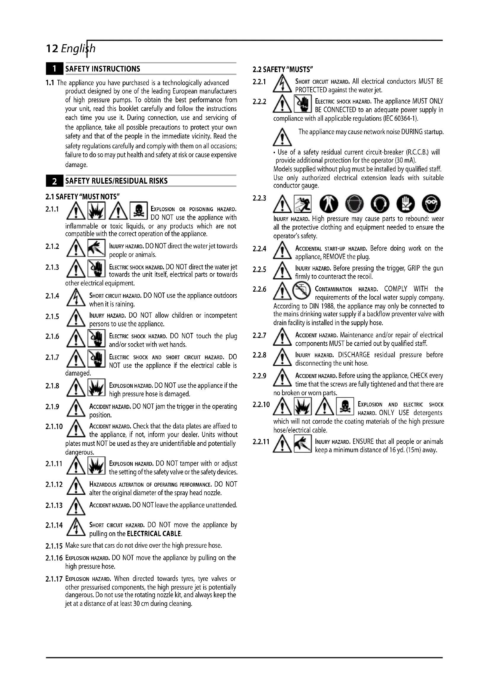
2.1.1 EXPLOSION OR POISONING HAZARD. DO NOT use the appliance with inflammable or toxic liquids, or any products which are not compatible with the correct operation of the appliance.
2.1.2 INJURY HAZARD. DO NOT direct the water jet towards people or animals.
2.1.3 ELECTRIC SHOCK HAZARD. DO NOT direct the water jet towards the unit itself, electrical parts or towards other electrical equipment.
2.1.4 SHORT CIRCUIT HAZARD. DO NOT use the appliance outdoors when it is raining.
2.1.5 INJURY HAZARD. DO NOT allow children or incompetent persons to use the appliance.
2.1.6 ELECTRIC SHOCK HAZARD. DO NOT touch the plug and/or socket with wet hands.
2.1.7 ELECTRIC SHOCK AND SHORT CIRCUIT HAZARD. DO NOT use the appliance if the electrical cable is damaged.
2.1.8 EXPLOSION HAZARD. DO NOT use the appliance if the high pressure hose is damaged.
2.1.9 ACCIDENT HAZARD. DO NOT jam the trigger in the operating position.
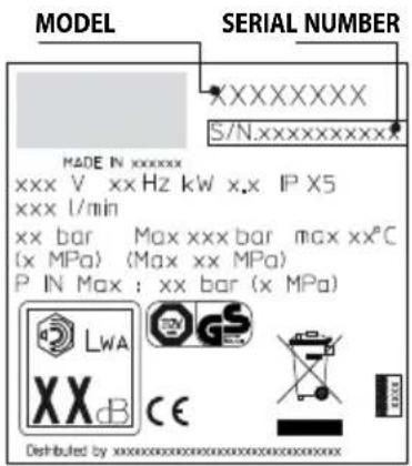
2.1.10 ACCIDENT HAZARD. Check that the data plates are affixed to the appliance, if not, inform your dealer. Units without plates must NOT be used as they are unidentifiable and potentially dangerous.
2.1.11 EXPLOSION HAZARD. DO NOT tamper with or adjust the setting of the safety valve or the safety devices.
2.1.12 HAZARDOUS ALTERATION OF OPERATING PERFORMANCE. DO NOT alter the original diameter of the spray head nozzle.
2.1.13 ACCIDENT HAZARD. DO NOT leave the appliance unattended.
2.1.14 SHORT CIRCUIT HAZARD. DO NOT move the appliance by pulling on the ELECTRICAL CABLE.
2.1.15 Make sure that cars do not drive over the high pressure hose.
2.1.16 EXPLOSION HAZARD. DO NOT move the appliance by pulling on the high pressure hose.
2.1.17 EXPLOSION HAZARD. When directed towards tyres, tyre valves or other pressurised components, the high pressure jet is potentially dangerous. Do not use the rotating nozzle kit, and always keep the jet at a distance of at least 30~cm during cleaning.
2.2 SAFETY "MUSTS"
2.2.1 SHORT CIRCUIT HAZARD. All electrical conductors MUST BE PROTECTED against the water jet.
2.2.2 ELECTRIC SHOCK HAZARD. The appliance MUST ONLY BE CONNECTED to an adequate power supply in compliance with all applicable regulations (IEC 60364-1).
The appliance may cause network noise DURING startup. Use of a safety residual current circuit-breaker (R.C.C.B.) will provide additional protection for the operator (30mA) Models supplied without plug must be installed by qualified staff. Use only authorized electrical extension leads with suitable conductor gauge.
2.2.3 INJURY HAZARD. High pressure may cause parts to rebound: wear all the protective clothing and equipment needed to ensure the operator's safety.
2.2.4 ACCIDENTAL START-UP HAZARD. Before doing work on the appliance, REMOVE the plug.
2.2.5 INJURY HAZARD. Before pressing the trigger, GRIP the gun firmly to counteract the recoil.
2.2.6 CONTAMINATION HAZARD. COMPLY WITH the requirements of the local water supply company. According to DIN 1988, the appliance may only be connected to the mains drinking water supply if a backflow preventer valve with drain facility is installed in the supply hose.
2.2.7 ACCIDENT HAZARD. Maintenance and/or repair of electrical components MUST be carried out by qualified staff.
2.2.8 INJURY HAZARD. DISCHARGE residual pressure before disconnecting the unit hose.
2.2.9 ACCIDENT HAZARD. Before using the appliance, CHECK every time that the screws are fully tightened and that there are no broken or worn parts.
2.2.10 EXPLOSION AND ELECTRIC SHOCK HAZARD. ONLY USE detergents which will not corrode the coating materials of the high pressure hose/electrical cable.
2.2.11 INJURY HAZARD. ENSURE that all people or animals keep a minimum distance of 16 yd. (15m) away.
3 GENERAL INFORMATION (FIG.1)/PAGE 3
3.1 Use of the manual
This manual forms an integral part of the appliance and should be kept for future reference. Please read it carefully before installing/ using the unit. If the appliance is sold, the Seller must pass on this manual to the new owner along with the appliance.
3.2 Delivery
The appliance is delivered partially assembled in a cardboard box.
The supply package is illustrated in fig.1.
3.2.1 Documentation supplied with the appliance
A1 Use and maintenance manual
A2 Safety instructions
A3 Declaration of conformity
A4 Warranty regulations
3.3 Disposing of packaging
The packaging materials are not environmental pollutants but must still be recycled or disposed of in compliance with the relevant legislation in the country of use.
3.4 Safety signs
Comply with the instructions provided by the safety signs fitted to the appliance.
Check that they are present and legible; otherwise, fit replacements in the original positions.
E1 symbol - Indicates that the appliance must not be disposed of as municipal waste; it may be handed in to the dealer on purchase of a new appliance. The appliance's electrical and electronic parts must not be reused for improper uses since they contain substances which constitute health hazards.
E2 symbol - Indicates that the appliance is intended for professional use, i.e. for experienced people informed about the relative technical, regulatory and legislative aspects and capable of performing the operations necessary for the use and maintenance of the appliance.
E3 symbol - Indicates that the appliance is intended for non-professional (domestic) use.
4 TECHNICAL INFORMATION (FIG.1)/PAGE 3
4.1 Envisaged use
This appliance has been designed for individual use for the cleaning of vehicles, machines, boats, masonry, etc, to remove stubborn dirt using clean water and biodegradable chemical detergents.
Vehicle engines may be washed only if the dirty water is disposed of as per regulations in force.
- Intake water temperature: see data plate on the appliance.
- Intake water pressure: min. 0,1MPa-max 1MPa.
- Operating ambient temperature: above 0^ .
The appliance is compliant with the EN 60335-2-79/A1 standard.
4.2 Operator
The symbol on the front cover identifies the appliance's intended operator (professional or non-professional).
4.3 Improper use
Use by unskilled persons or those who have not read and understood the instructions in the manual is forbidden.
The introduction of inflammable, explosive and toxic liquids into the appliance is prohibited.
Use of the appliance in a potentially inflammable or explosive atmosphere is forbidden.
The use of non-original spare parts and any other spare parts not specifically intended for the model in question is prohibited.
All modifications to the appliance are prohibited. Any modifications made to the appliance shall render the Declaration of Conformity null and void and relieve the manufacturer of all liability under civil and criminal law.
4.4 Main components
B1 Adjustable spray nozzle B5 High pressure hose
B2 Lance B6 Detergent tank
B3 Gun with safety catch (on models with this feature)
B4 Power supply cable with plug (on models with this feature)
4.4.1 Accessories (if included in the supply package - see fig.1).
C1 Nozzle cleaning tool C7 Pipe drain kit
C2 Rotating nozzle kit C8 Large surface
C3 Handle cleaning tool
C4 Brush C9 Adapter
C5 Hose reel C10 Lubricating grease tube
C6 Water suction kit (where supplied)
4.5 Safety devices
Caution - Danger!
Do not tamper with or adjust the safety valve setting.
- Safety valve and/or pressure limiting valve.
The safety valve is also a pressure limiting valve.
When the gun trigger is released, the valve opens and the water recirculates through the pump inlet or is discharged onto the ground.
- Thermostat valve (D1 where fitted)
If the water temperature exceeds the temperature set by the manufacturer, the thermostat valve discharges the hot water and draws in an amount of cold water equal to the amount of water discharged, until the correct temperature is restored.
- Safety catch (D): prevents accidental spraying of water.
5 INSTALLATION (FIG.2)/PAGE.4
5.1 Assembly
Caution - Danger! All installation and assembly operations must be performed with the appliance disconnected from the mains power supply.
The assembly sequence is illustrated in fig.2.
5.2 Assembling the rotating nozzle
(For models with this feature)
The rotating nozzle kit delivers greater washing power.
Use of the rotating nozzle may cause reduction in pressure of 25% compared to the pressure obtained with the adjustable nozzle. However, the rotating nozzle kit delivers greater washing power due to the rotation of the water jet.
5.3 Electrical connection
A Caution - Danger!
Check that the electrical supply voltage and frequency (V-Hz) correspond to those specified on the appliance data plate (fig.2). The appliance should only be connected to a mains power supply equipped with an adequate earth connection and a differential security breaker (30mA) to cut off the electricity supply in the instance of a short circuit.
5.3.1 Use of extension cables
Use cables and plugs featuring "IPX5" protection level.
The cross-section of the extension cable should be proportionate to its length; the longer it is, the greater its cross-section should be. See table I/PAGE 6.
5.4 Water supply connection
Caution - Danger! Only clean or filtered water should be used for intake. The delivery of the water intake tap should be equal to that of pump capacity.
Place the appliance as close to the water supply system as possible.
5.4.1 Connection points
Water outlet (OUTLET)
Water inlet with filter (INLET)
5.4.2 Connection to the mains water supply
The appliance can be connected directly to the mains drinking water supply only if the supply hose is fitted with a backflow preventer valve as per current regulations in force. Make sure that the hose is at least 0.13mm and that it is reinforced.
6 ADJUSTMENT INFORMATION (FIG.3)/PAGE 5
6.1 Adjusting the spray nozzle (for models with this feature) Water flow is adjusted by regulating the nozzle (E).
6.2 Adjusting the detergent (on models with this feature) Detergent flow is adjusted using the regulator (F).
6.3 Adjusting the detergent pressure
Set the adjustable nozzle (E) on " to deliver detergent at the correct pressure (on models with this feature).
6.4 Adjusting the pressure (on models with this feature)
The regulator (G) is used to adjust the working pressure. The pressure is shown on the pressure gauge (where fitted).
7 INFORMATION ON USE OF THE APPLIANCE (FIG.4)/PAGE 5
7.1 Controls
- Starter device (H).
Set the starter switch on (ON/1) to:
a) start the motor (in models without TSS device);
b) set the motor ready to start (in models with TSS device).
If there is a pilot light on the starter device, it should light up.
If the "low/high" settings are available, use them as follows:
Low: low pressure washing
High : high pressure washing
Set the starter device switch on (OFF/0) to shut down the appliance.
If there is a pilot light on the starter device, it should go out.
Water jet control lever (I).

Caution - Danger!
During operation the appliance must be positioned as shown in fig. 4 on a sturdy, stable surface.
7.2 Start-up
1) Turn on the water supply tap fully.
2) Release the safety catch (D).
3) Depress the gun trigger for a few seconds and start up the appliance using the starter device (ON/1).

Caution - Danger!
Before starting up the appliance check that the water supply hose is connected properly; use of the appliance without water will damage it; do not cover the ventilation grilles when the appliance is in use.
TSS models - In TSS models with automatic delivery flow cut-off system:
- when the gun trigger is released the dynamic pressure automatically cuts out the motor (see fig.4);
- when the gun trigger is depressed the automatic drop in pressure starts the motor and the pressure is restored after a very slight delay;
- if the TSS is to function correctly all gun releasing and depressing operations must be performed at intervals not less than 4-5 seconds at least.
On three-phase models for professional use: at first use, start the appliance for a very short time to check that the motor is running in the correct direction. If the motor fan is turning anti-clockwise, exchange two of the three phase wires (L1, L2, L3) in the electrical plug.
To prevent damage to the appliance, do not allow it to operate dry and when running do not stop the water jet for more than 10 minutes at a time (for models without TSS device).
7.3 Stopping the appliance
1) Set the starter device switch on (OFF/0).
2) Depress the gun trigger and discharge the residual pressure inside the hoses.
3) Engage the gun safety catch (D).
7.4 Restarting
1) Release the safety catch (D).
2) Depress the gun trigger and discharge the residual air inside the hoses.
3) Set the starter device on (ON/1).
7.5 Storage
1) Switch the appliance off (OFF/0).
2) Remove the plug from the socket.
3) Turn off the water supply tap.
4) Discharge the residual pressure from the gun until all the water has come out of the nozzle.
5) Drain and wash out the detergent tank at the end of the working session. To wash out the tank, use clean water instead of the detergent.
6) Engage the gun safety catch (D).
7.6 Refilling and using detergent
When using detergent, the adjustable nozzle must be set on " (on models with this feature).
Use of a high pressure hose longer than the one originally supplied with the cleaner, or the use of an additional hose extension, may reduce or completely halt the intake of detergent.
Fill the tank with highly degradable detergent.
7.7 Recommended cleaning procedure
Dissolve dirt by applying the detergent mixed with water to the surface while still dry.
When dealing with vertical surfaces work from the bottom upwards. Leave the detergent to act for 1-2 minutes but do not allow the surface to dry. Starting from the bottom, use the high pressure jet at a minimum distance of 30~cm . Do not allow the rinse water to run onto unwashed surfaces.
In some cases, scrubbing with brushes is needed to remove dirt.
High pressure is not always the best solution for good washing results, since it may damage some surfaces. The finest adjustable nozzle jet setting or the rotopower nozzle should not be used on delicate or painted parts, or on pressurised components (e.g. tyres, inflation valves, etc.).
Effective washing depends on both the pressure and volume of the water used, to the same degree.
8 MAINTENANCE (FIG.5)/PAGE 6-(FIG.6)/PAGE 144
Any maintenance operations not covered by this chapter should be carried out by an Authorized Sales and Service Centre.

Caution - Danger!
Always disconnect the plug from the power socket
before carrying out any work on the appliance.
8.1 Cleaning the nozzle
1) Disconnect the lance from the nozzle.
2) Remove any dirt deposits from the nozzle hole using the tool (C1).
8.2 Cleaning the filter
Inspect the intake filter (L) and detergent filter (if fitted) before each use, and clean in accordance with the instructions if necessary.
8.3 Unjamming the motor (on models with this feature)
In case of lengthy stoppages, limescale sediments may cause the motor to seize. To unjam the motor, turn the drive shaft with a tool (M).
8.4 End-of-season storage
Treat the appliance with non-corrosive, non-toxic antifreeze and lubricate the O-rings using the lubricating grease tube (where supplied) (C10) as shown before storing it away for winter.
Put the appliance in a dry place, protected from frost.
9 TROUBLESHOOTING
| Problem Possible causes Remedy | ||
| Pump does not reach working pressure | Nozzle worn Replace nozzle | |
| Water filter fouled Clean filter (L) (fig.5) | ||
| Water supply pressure low Turn on water supply tap fully | ||
| Air being sucked into system Check tightness of hose fittings | ||
| Air in pump | Switch off the appliance and keep depressing and releas-ing the gun trigger until the water comes out in a steady flow. Switch the appliance back on again. | |
| Adjustable nozzle not positioned correctly Turn the adjustable nozzle (E) (+) (fig.3) | ||
| Thermostatic valve tripped Wait for correct water temperature to be restored | ||
| Pressure drops during use | Water intake from external tank Connect appliance to the mains water supply | |
| Intake water too hot Reduce temperature | ||
| Nozzle clogged Clean nozzle (fig.5) | ||
| Intake filter (L) dirty Clean filter (L) (fig.5) | ||
| Motor "sounds" but fails to start | Insufficient power supply | Check that the voltage of the mains power supply line is the same as that on the plate (fig.2) |
| Voltage loss due to use of extension cable | Check characteristics of extension cable | |
| Appliance not used for a long period of time | Contact your nearest Authorized Service Centre | |
| Problems with TSS device | Contact your nearest Authorized Service Centre | |
| Motor fails to start | No electrical power | Check that the plug is firmly in the socket and that the mains voltage supply is present (*) |
| Problems with TSS device | Contact your nearest Authorized Service Centre | |
| Appliance not used for a long period of time | Using the tool (M) unjam the motor from the hole at the rear of the appliance (in models with this feature) (fig.5) | |
| Water leakage | Seals worn | Have the seals replaced at your nearest Authorized Service Centre |
| Safety valve tripped and discharging | Contact an Authorized Service Centre | |
| Appliance noisy | Water too hot | Reduce temperature (see technical data |
| Oil leakage | Seals worn | Contact your nearest Authorized Service Centre |
| TSS versions only: motor starts even with gun trigger is released | High pressure system or pump hydraulic circuit not watertight | Contact your nearest Authorized Service Centre |
| TSS versions only: no water delivery when gun trigger is depressed (with supply hose connected) | Nozzle clogged Clean nozzle (fig.5) | |
| No detergent taken in | Adjustable nozzle on high pressure setting | Set nozzle on " " setting (fig.3) |
| Detergent too dense | Dilute with water | |
| High pressure hose extension being used | Fit original hose | |
| Deposits or restriction in detergent circuit | Flush with clean water and eliminate any restrictions. If the problem persists, contact an Authorized Service Centre | |
(*) If the motor starts and does not restart during operation, wait 2-3 minutes before repeating the start-up procedure (overload cutout has been tripped). If the problem recurs more than once, contact your nearest Authorized Service Centre.
EN EC Declaration of conformity
We Annovi Reverberi S.p.A., Modena, Italy declare that the following Black & Decker Machine(s):
Designation of Machine
High Pressure Washer
Model No /Type
PW1600WS
Input power
1,6kW
Conforms to the following European Directives: 2006/42/EC, 2006/95/EC, 2002/95/EC, (2011/65/EC), 2002/96/EC, 2004/108/EC, 2000/14/EC
And are manufactured in accordance to the following standards or standardised documents: EN 60335-1; EN 60335-2-79; EN 55014-1; EN 55014-2; EN 61000-3-2; EN 61000-3-3; EN 61000-3-11; EN 60704-1 Name and address of the person in charge to give the technical file: Stefano Reverberi / AR Managing Director Via M. L. King, 3 - 41122 Modena, Italy The conformity assessment procedure required by Directive 2000/14/ was in accordance with annexV
Measured Sound Power Level: 93 dB (A)
Guaranteed Sound Power Level: 94 dB (A)
Date:25.10.2012
MODENA (I)
Stefano Reverberi

Technical Data
| Technical Data (EN) Unit | PW1600WS | |
| Output | I/min | 6 |
| Pressure | MPa | 8 |
| Maximum pressure | MPa | 12 |
| Power | kW | 1,6 |
| T° input | °C | 50 |
| Maximum input pressure | MPa | 1 |
| Repulsive force of the gun to the maximum pressure | N | 9,1 |
| Motor Insulation | - | Class F |
| Motor Protection | - | IPX5 |
| Voltage | V/Hz | 220-240/50-60 |
| Maximum allowed net impedance | Ω | - |
| Sound levelK = 3 dB(A): LFA(EN 60704-1) LWA(EN 60704-1) | dB (A) 86dB (A) 94 | |
| Unit vibrationsK = 1,5 m/s2: | m/s2 | 2,11 |
| Weight | kg | 7,2 |
Subject to technical modifications!
(EN) WARRANTY
The duration of the warranty is in accordance with the relevant legislation in the country where the product is sold (unless otherwise stated by the producer).
The warranty covers materials, construction and conformity defects during the warranty period, during which time the manufacturer will replace defective parts and repair or replace the product if excessively worn in normal use.
The warranty does not cover components subject to normal wear (valves, pistons, water gasket, oil gasket, springs, O-rings, accessories such as hoses, guns, brushes, wheels, etc.).
The warranty does not cover defects caused by or resulting from:
- incorrect use, abuse or neglect,
- trade, professional or hire use,
- failure to service and maintain the unit as specified in the user's manual,
- unauthorised repairs,
- use of non-original accessories/spare parts,
- damage incurred during shipping or due to foreign objects or substances and accidental damage,
- warehousehousing and stock keeping problems.
To register the warranty, the customer must provide proof of purchase.
2 SICHERHEITSVORSCHRIFTEN/RESTGEFAHREN
2.1WARNHINWEISE:UNZULASSIG
Stefano Reverberi Managing Director
Technische Daten
Stefano Reverberi / AR Managing Director
Via ML King, 3 - 41122 Modena, Italia
Stefano Reverberi Managing Director

Dati Tecnici
2006/42/CE, 2006/95/CE, 2002/95/CE, (2011/65/CE), 2002/96/CE, 2004/108/CE, 2000/14/CE
Stefano Reverberi Managing Director
Datas Técnicos
8 MANUTENÇA (FIG.5)/PÁGINA 6 - (FIG.6)/PÁGINA 144
Stefano Reverberi Managing Director
Dados Técnicos
2) AvoTe to mIoAoi kai aoeiaote Tny nieon ano to eawtepiKo twv oWanywewv.
3) BalaTe to diaKoTnTo nToeon (ON/1).
8 SYNTHPHsH (EIK.5)/SEAIIAA.6-(EIK.6)/SEAIIAA 144
OLe o EneuPaeic ouvtipnong nou dev nepiiaubavovtai oTo napov Kepealao npenei va yivovta e eva ecouioobotnevo Kevtro pwnanckai Teyviknc YIooTpiEnc.

Npoox-Kivovoc!
Piv ano onoiabnote eneuaon oTo unxavna Byalte to 0 npia peuatoc.
2006/42/EK, 2006/95/EK, 2002/95/EK, (2011/65/EK), 2002/96/EK, 2004/108/EK, 2000/14/EK
Kai napayetal(ovtai) ouuovva u ta akoloutheta npotuna t a akoloutheta tunooinvya evypapa: EN 60335-1; EN 60335-2-79; EN 55014-1; EN
55014-2; EN 61000-3-2; EN 61000-3-3; EN 61000-3-11; EN 60704-1
Ovoja Ka iieuovon Tou uneovou ytn xopnyon Tou texvko
φακελού: Stefano Reverberi / AR Managing Director - Via ML King, 3 - 41122 Modena, Italia
H diaikaoia aioyongnc tnc omuoppwocn noia anaitei a ano tvv obnyia 2000/14/EK exi ekteaeotei oupwva me to Pooaptnma V
Meptn0eioa oiao nynxntiknc loxuoc: 93 dB (A)
Eyyunqevn otadun nxtiKnc 1oxuoc:94 dB (A)
Stefano Reverberi Managing Director

Texvika otoixeia
Stefano Reverberi Managing Director
Tecnische Gegevens
5 INSTALLATION (FIG. 2)
5.1
ALLATION (FIG.2)
5.1
Advarsel -fare!
8.4 Opbevaring for winter
2006/42/EF, 2006/95/EF, 2002/95/EF, (2011/65/EF), 2002/96/EF, 2004/108/EF, 2000/14/EF
8 VEDLIKEHOLD (FIG. 5)/SIDE 6 - (FIG. 6)/SIDE 144
2006/42/EF, 2006/95/EF, 2002/95/EF, (2011/65/EF), 2002/96/EF, 2004/108/EF, 2000/14/EF
4 TEKNISET TIEDOT (KUVA 1)/SIVU 3
4.1 Käytötarkoitus
2006/42/EY, 2006/95/EY, 2002/95/EY, (2011/65/EY), 2002/96/EY, 2004/108/EY, 2000/14/EY
2.1 ZAKAZANE CINNOSTI
2.1.1 NEPOUZIVEJTE pristroj ve spojeni s hoIavymi nebo Jedovatymi kapalinami, nebo s vyrobky, ktere nejsou slučitelné se spravnou funkci pristroje. HROZINEBZPECI VYBUCHU NEBO OTRAVY
2.1.2 NESMÉRÜJTE proud vody na osoby nebo zviñata. HROZÍ NEBEZPEÇI ZRANÉNI
2.1.3 NESMÉRÜJTE proud vody smérém k samotnému pristroji, elektrickým soucástem nebo jinym elektrickým zaizéním. HROZI NEBZEPCI URAZU ELEKTRICKYM PRODEM
2.1.4 NEPOUZIVEJE T P ristroj ve venkovnim prostredi, pokud prsi.HROZI NEBZPECI ZKRTU
2.1.5 ZABRANTPEPOUZITiPfistroje detmi nebo nekompetentnimi osobami.HROZI NEBEZPECI ZRANENI
2.1.6 NEDOTYKEJTE se zastcky a/nebo zasuvky mokryma rukama. HROZI NEBZPECI URAZU ELEKTRICKYM
PROUDEM
2.1.7 NEPOUZIVEJTE pristroj v pripadé, ze je poskozený elektrický kabel. HROZI NEBEZPECI URAZU ELEKTRICKYM PROUDEM A ZKRATU
2.1.8 NEPOUZIVEJTE pristroj v pripadé, ze je poskozená ysvokotláká hadice. HROZI NEBEZPECI VYBUCHU
2.1.9 NEBLOKUJE spoust v pracovni poloze. HROZI NEBEZPECI NEHODY
2.1.10 Zkontrolujte typovy stitek pripevneny k pristroji;Pokud zde neni, informujte svheho dodavatele. Pristoje neopatfene typovym stitkem NESMI byt pouzivany, protoze je neni:nozne identifikovat a jsou proto potenciánlne nebezpečné. Hrozi NEBEZPECI NEHODY
2.1.11 NEMANIPULUJE ani nemeinte nastaveni pojistneho ventilu ci bezpecnostnich zaizeni. HROZI NEBEZPECI VYBUCHU
2.1.12 NEMENTEpuvodni prumér hlavovr ozstfikovaci trysky. HROZI NEBEZPECI ZMENY PROVOZNICH VYKONU
2.1.13 NEPONECHAVEJTE pristroj bez dozoru. HROZI NEBEZPECI NEHODY
2.1.14 NEPRESOUVEJTE pristroj tazenim za elektricky kabel. Hrozi NEBEZPECI ZKRATU
2.1.15 Zajistete,aby vozidla NEPREJIZDELA pres yvsokotlaké hadice.
2.1.16 Nepremistujte pristroj ta hem za vysokotlakou hadici. HROZI NEBEZPECI VYBUCHU
2.1.17 Vodni paprsek nesmi dopadat primo na pneumatiky, ventily pneumatik ani jiné dily, ktere jsou pod tlakem, protoze by je mohl poskodit. Nepouziveje toupravu s rotačni tryskou a pri Čisteni neustále dodržujte vzdalenost min. 30 cm. HROZI NEBEZPECI VYBUCHU
2.2 POVINNE CINNOSTI
5 INSTALACE (OBR.2)/STRANA 4
5.1 Montáz
Upozornéni - Nebezpeci!
2006/42/ES, 2006/95/ES, 2002/95/ES, (2011/65/ES), 2002/96/ES, 2004/108/ES, 2000/14/ES
Stefano Reverberi / AR Managing Director - Via ML King, 3 - 41122
Modena, Italie
INSTALACJA (RYS.2)/STRONA 4
5.1 Montaz
2006/42/WE, 2006/95/WE, 2002/95/WE, (2011/65/WE), 2002/96/WE, 2004/108/WE, 2000/14/WE
Stefano Reverberi Managing Director

Dane techniczne
2006/42/ES, 2006/95/ES, 2002/95/ES, (2011/65/ES), 2002/96/ES, 2004/108/ES, 2000/14/ES
9 RIESENIE PROBLEMOV
2006/42/ES, 2006/95/ES, 2002/95/ES, (2011/65/ES), 2002/96/ES, 2004/108/ES, 2000/14/ES
Stefano Reverberi / AR Managing Director - Via ML King, 3 - 41122
Modena, Taliansko
Stefano Reverberi Managing Director
Technické udaje
| Technické udaje (SK) | Jednotka | PW1600 WS |
| Vystup | I/min | 6 |
| Tlak | MPa | 8 |
| Maximálny tlak | MPa | 12 |
| Vykon | kW | 1,6 |
| Vstrupné teplota | °C | 50 |
| Maximálny vystupné tlak | MPa | 1 |
| Odporová sila pistole pri maximálnom tlaku | N | 9,1 |
| Izolácia motora | - | Trieda F |
| Ochrana motora | - | IPX5 |
| Napägia | V/Hz | 220-240/50-60 |
| Maximálne pripustné siefová impedancia | Ω | - |
| Üroven zyuku (K = 3 dB(A)): | ||
| Lp4 (EN 60704-1) | dB (A) 86 | |
| Lw4 (EN 60704-1) | dB (A) 94 | |
| Vibrária zariadenia(K = 1,5 m/s2): | m/s2 | 2,11 |
| Hmotnost | kg | 7,2 |
3.4 3haun3a6e3oNaCHOCT
Cn3BaIte HNCTpyKUInTe, yKa3aHn Ha 3HaunTe 3a 6e3oNaCHOCT, NOCTABEHn Bbpxypepa.
YBepete Ce, Ye Te Ca HauuHn N YeTINB; B npOTMBEN CnyaH NOCTABETHOBN TAKIBA Ha IbPBOHauHNTIe MM MECTA.

CMMBOE1-Poka3Ba,YeypeBt He Tp86Ba da ce u3XbPnA
6HOBNTOOTnabu;MOKeJa6bDeBbPhaHaDnBpa npn NOKyNka HAOB ype. ENEKTPnuecknte n ENEKTPoHHn actn Ha ypea He 6Ba Da 6BdATnON3BAHN NOBtPOHO 3a HENODXODUIN CEIN, Tb KATO cbDbpxat BeueCTBa, KOINTo IpeIcTbIIBAT OAnCHOCT 3a 3dpABeto.

CMMBON E2-O3NaHcAba, YepeDbTe npedHa3NaHcH 3a npoepocnoHaHa
ynoTpe6a,TOeCT 3a OINTHN XOpA, INHOPMnPAHn 3a OTHOCInENHMe TexNHueckn, perynatopHN I 3AKOHOB ACNEKTH, n CnOC6HN Da N3BbPWBAT npouepytne, Heo6xOdMM 3a HNOJ3BaHETo NIOJDPbKkata Ha ype#.

CmB0n E3 - O3Haayaba, Ye ypebTe npedHa3Hauehen 3a
HnepofoecnohaHa (DomaHa) yntope6a.
4 TEXHNUECKA INHOPMALI (INI.1)/CTPAHNIa 3.
4.1 PpeHa3NaeHne
To3ypeepnpehna3hauehen 3a HmHbMnyaHa HnyoTpe6a 3a noocCTBaHe Ha ABTOMO6BNI, MaNNHN, NoKIN, CTeHN n Dp., C cEN oTcpanBaHe Ha yOpNTn 3aMbpcBAHNA, KaTO IN3No13Ba YnCTa BODa N 6nopa3rpaXdaNce XIMnueckn DeTepreHTN.
BnrrnHa ABtOMOBmMOrat Da Ce NoHCTBaT CaMO Ako CE m3noJI3Ba HEnIeHa BODA B CbOTBeTcTBHe C DeiCTBaUaT HopMaTHBHa ype6a.
TemnepaIpaHaNoemahataBoda:Bux TabekataCTexHueckn daHHn Ha ypeia.
HaIraHHe Ha NoeMaHaTa BOJa: no106apa.
CMyKaTeHNOHaJIraHe 3a BOda:MnH.0,1MPa-makc.1MPa.
YpeBt Cb0TBeCTBa Ha CTaHApT eN 60335-2-79/a1.
4.2 Oneparop
CIMBOBnT Ha npedHnKanak onpeJEA 3a KaKB onepatope npedHa3NaeH yepbT (npocnoHnIcT Hn HnpocecnoHnIcT).
4.3 Ynortpe6a He no npedna3hauene
3a6paheHa e ynoptepaota OT HeKbaHmHnpuHn mua nO TAKMBA, KOMTO He ca npoeHHn pa3bpaun HNCTpykUInTE B pkoBOCDBOTO.
3a6paHeO e b ypeDa da ce nocTabr Bb3nnaMeHHM, B3pNBOOnacHn IN TOKcHmTeHOCTH.
3a6paheHa e pa6oTa c ypea B nOteHuaJIHO Bb3nAmEHMa nnB3pNUOAncha aTMocepa.
I3noI3BaHETo Ha HeOpnIHahJIHn pe3epBHN qaCTn I npytn pe3epBHN qactn, KOITo HE Ca KOHKpETHo ppeHa3hauEHm 3a BbnpOCHM moJe, e 36paHeo.
3a6paheHo e da e 3BbPWBat KaKBrTo n Da 6nIO MoNphiKaun Ha ypeJa. BcKaKBN MoNphiKaun, N3BbPweHN Bpxyypea, Oe3CunBaT n aHynpat DeKnapaueta 3a CbOTBECTBne MOCBOOxJabAT npoN3BOUTeIg OT BCKaKBA OTROBOPHOCT NO rpaXdAHCKO t Haka3ATEHOTnpaBO.
4.4 TnabHn KOMNOHEHTN
B1 Perynpyem HakpaimHK cdo3a B5 Mapkyu 3a BncoKo Hanrahe
B2 YdbnKHTenHa Tpb6a
B6 Pe3epBoaap 3a deteprent (npn
B3ПсТОЛСпpeДиЗИТEN
Moei n TcBa npncnoc6bnne
B4 3axpaHbauKabenCcienen (npnMoJennCTOBA npncIOco6JeHne)
4.4.1 Akcecoapu (ako ca docmaebu cypeba -bk.duz.1)
C1 Pn60p 3a noMCTBaH He IIO3aT
C7 KOMnIeKTe 3a nouCTBaHe
C2 KomJIeK T BbPTaI CE HApKaIIHnK
Ha OTBODHnTeJHa Tpb6a
C3 Dpbkka
C8 KomnneKT- Yetka
C4 Yetka
3aTOJEMNIIOBbPXHOCTM
C5 PoJka 3a Mapkyu
C9 KomJIeKt aadAnTepei
C6 KomnneKT -McMyKbaHe
C10 Ty6nka cma3oHa rpec
Ha Boda
(aKo e doctabeHa)
4.5 Ipepa3n yctpoCTBa

Bhumahue - onachocm!
He npomehaIte HnepepyunpaTHe hactpoiKaTaHa npedna3HH
Knanah!
063onacnteneBentnIIN/nnOrpaHuaaHaHaRaHetoBentnI.
Pepnna3HnT Knanan e n Knanan 3a Orpanuabahe Ha HanraHTo. Pnpocbo6oxdaBaHe Ha CkycbKa BEHTnBt Ce OTbApn NBOgata N3BbPbBapeunpkyuaqnPiep3 BXOJa HA NOMnTa INN IN3TuHa 3eMrtA.
- Knanan ha mepmocmama (D1 npM MOHTmpaHe)
Ako TEmnepatypata Ha BODATA HaXxBpIa 3aIaHeHATA O npOIm3BODITen, KlaIaNbT Ha TepMOCTATA N3IpyCKa IopeuA BODa HIOEMA CbUOTO KONUcETBO CTyEHa DO Bb3ctAHOBRABa He TEmnpatypata.
- Pnpda3nTEn (D): npdeotBpTaRb CnyauHno Tnpckane Ha BOda.
5 INHCTAJINPAHE (ΦNΓ.2)/CTPAHIV4.
5.1 MoThax

Bhumahue - Onachocm!
Bcukn onepaun no nHctanpahe m MONTAK Tp6ba da ce RaBat, KORAto ypebt e 3KIOueh OT eNEKtpo3axpaHBAHeto.
MOtakKhata nocieIobateJIHOCT e IIOHcTpnpaHa Ha 2.
5.2 MoHTIpaHae HaBbPTaUncce HAKpaHnK
(3a moDeni C ToBa npncnoc6neHme).
KOMIIeKbT BbptAa Ce HApainHcOcIpyBa NO-tOIaMa MoUHOCT Ha 3MBAHe.
3N0JI3BaHcTo Ha BpTaHcMa Ce HApainHcMoKe Da npuHm Do 25% cnaHa
Ha HAnraHcTe, BcPabHeHcMe CTOB aPi N3IOJI3BaHe Ha peryInpMy E HApaiHnK.
KOMIIeKbT BbptAa Ce HApainHcU, Obae, Daba No-tOIaMa rBbKaBOCT
ppn MneHe Nopadn BbptEHeTo Ha BOdHata Ctpy.
5.3 Cbbp3BaHe KbMe nEeKtpnueckata Mpeka

Bhumahue - Onachocm!
PpOBepTe Danu HanpeKeHHeTo u cectotata (V - Hz) Ha eneKTPoCHA6DHTENHATA MPExa OTROBAPr HA CTOHOCHTte, NocOeHN Ha TAbEKNATA Ha ypeA (Phi. 2). YpeBt TPA6Ba Da ce CBp3Ba Camo KbM MpeKO BO eNEKTPo3axpanBaHe, Cn6deHO C nOxODNIO 3aEMBAHe m dfepeHuaen 3aunien HpeKcbau Ha Bepurata (30 mA), 3a da ce npkebcne IodabAHeto Ha HanpeKeHHe Bcuya H KaCo CbeINHeHne.
5.3.1 ⅢnON38aHeHa yobJxumenu Ka6enu
M3noJ3BaIte Ka6eHn HcncenC nHbO Ha 3aunTa iPX5.
HanpehTo ceyHHe Ha npoBOnHka Ha yblnKTHenHna Ka6eT pr6Ba da 6bde cBoTBeTHO Ha dlNkHATA My - npn no-roJMA dbNkHa HanpehTo ceHHe Tpr6Ba da e no-roJMA.Bx. Tablania i.
5.4 Cbbp3BaHe KbM BODOpPObOda

Bhumahue - Onachocm!
Iodabahata BODa MoKeJa 6bJe cAmO uCTa HnHΦHTpnpHa. De6ntb Ha KpaHa 3a Iodabae Ha BODa TpR6Ba Da ce paBnRa Ha kanaunTeHa NOMnTa.
IocTabeTe ypea KOnKToCe MoKe No-6m3Ko Do BOOpnpOBoHata ChCTema.
5.4.1 ToKu Ha C8bP3aHe
- 3xOHaBoDaTa(OutLet)
Bxod3aBogataCfnnTbp (iNLet)
5.4.2 C6bp3BaHe KbM BODOpOBoDhama MpeXa
YpeBt Moke da ce CbP3Ba DnpeKTHo KbM BODOnpOBoDHaT a MpeKa C nTeHa BOa cAmo Ako Mapkyb3 a NDoBaHe e Ch6BeH c Knaan 3a CnpaHe Ha O6paTHnI NOTOK, B CbOTBetCTBne C dEiCTBaUATA HopMaTHnBA ype6a. MapKybT pr6Ba Da e C dAmemTppoNE 13 MM Na a epmuaH.
6 INHOPMAUJRA3A PEGYIIMPAHETO (ΦNΓ.3)/CTPAHILA5.
6.1 PerynnpaHaHaKpaHnKa CIO3a (3a MoeJIc TTOBa pIncNocO6neHne) IToTOKbHe BOdaTepe rypma Ype3 HaKpaHnKa (E).
6.2 D03npaHe Ha DetepreHrA (PnM MoEn C TOBa PnpCnOc6NeHne) ITOKbT Ha DetepreHTa Ce Do3npa C peryNatop (F).
6.3 Perynnpahe Ha halaerheto Ha deteprehta
Hactpoite perynpyemata 103a (E) Ha" 3a da n3nyckaTe detepreHT c npabunHO Hnrahe (npm moen C TOBA npncnoc6neHne).
6.4 Perynnaphe ha hanaheTo (npm moedin c TOBA npncnoc6neHne)
Perynatopbt (G) ce m3non3Ba 3a hactpoiKa Ha pa60THOTo HanaIraHe. HanaIraHeto e nok3aHO Ha maHOMeTbpa (ako e noCTabEN).
7 INHOFPMAU3A N3IIOJI3BAHE HA YPEDA (ΦM.4)/CTPAHUIA 5.
7.1 OpraHn 3a ynpabBneHne
- CtapTePhO yctPoIcTBo (H).
Ioctabete KIOUa Hc StapTepa B No3nua (ON/I), 3a da:
a)стурахе мотopa (прим поеди 6e3 TSS yctpoiuctro);
6) nojrotbnte motopa 3a cTaptnpahe (npn moen n c TSS yctpoctBo).
Ako Ima KOHTponla lamna HcTAPTOBTO yCTPOCTBO, Tp6Ba Da CBETHE
Ako ca haIunHn HAcTpoHnKe "low/high" (BnCOKo/HnCKo), m3noJ3BaIte rM, KaKTO CneBa:
Low (Hncko): MmHe npu Hncko Hanrahe
High (BmCOKO): MmHe npu BmCOKO HalaRahe
IocTabeTe KJIIOUa HA cTApTeBa NIOImu (OFF/0), 3a Da I3KJIIOUHTe Yepea:
Ako mHa KOHTpOHa nMaHa cTApTOB OTo yCToIcTBo, Tp8Ba Da yTaCHe.
-Loctye3a ynpabnEHe Ha BODHaTa Ctpya (I).

Bhumahue - Onachocm!
IbpeHa pa6oTa ypeBt Tp86Ba da 6bde nocTabeH, KaKTo e
HO ha 4,Ha 3dpaba,ctabnha ochoba.
7.2 Iyckahe
1) OTBOPeTe DOKpaI KpaHa 3a NODaBaHe HbOda.
2) Ocbo6oDeTe npedna3nTena (D).
3) HATNCHETE cnycbka Ha nIcTOneta 3a hKoIko cekyHn n nyChete ypeia, KATO HATNCHETE KJIIOUa B No3mua (ON/1).

Bhumahue - Onachocm!
PpndnyckaneHa ypea ce ybepete,Ye mapkybt 3a nodaBahe
Ha Boda e CBpb3aH npabHnHO; n3non3BaHTo Ha ypeDa 6e3 Boda ige doBede do nobpeXdHeTo My; He noKpNBte BEHTMaOnHHTe peWetKn, dOKato ypeBbT pa6OTn.
Moden TSS -Pn moenn TSS cbc cnctemn 3a ABTOMATNUH CNPAhe Ha notoka:
KORATO CnycbkbT Ha NICTOeta Ce OTnyche, DNHaMMHOTo HAnraHe ABTomATMHO CNnpa eneKTpOMToPA (BIX qnr.4);
KORATO CNycbkBT Ha NCTOJEt a Ce HATNCHE, ABOTOMuHHTO cNaJaHe Ha HAnraHaTe CTAPmAp eNEKTpOMOTOpa n HAnraHaTe Ce Bb3TaHOBRA bCnED MHORo KpATKO 3abABHe;
-3a da ΦyHKUOHpa TSS npabUNHO, BCNUK onepaun no OTNcKaHe n HATnCKaHe Ha cnycbKa Tp86Ba da ce N3bJIHraBt Ha INTePbAIn, NO-MaNKo ot 4-5 cekyHn;
Pn Tpna3hne Moeenn 3a npoepcnohanny nnotpe6a npn Pbba yntpe6a nchene ypea 3a MHOK pKaTHO BPEM, 3a da npOBepnT aHIMOTOpBt 3aDbNKBa B npabHHATA NOcKa. AKO BENTnAtoptbHa MOTopa ce BbPTn O6paTHo Ha cAcOBHNKOBATA CTePLKa, CMeHETe MeCTaHa DBA OT Tpnte PAnOBn npoBoDnKa (L1, L2, L3) B enEeKPNueckn KONTAKT.
3a da npedotbpatnte qtetn 3a ype, he pa3pewabnre paobota ha cyxo n He cnnpaite BODHATA cTpy 3a noBee oT 10 MmHyTN (3a moen 6ez ycptpoCTBO TSS).
7.3 Cnnpahe na ypepa
1) NocTabeTe KInOuHa cStapTepeB nO3nUa(OFF/0).
2)HaTnCHHe TcNcBka Ha NtCToIeTa NOCBO6OTe OCTaTbHOTo HAnrAhe BbTpe B MapKyuNTe.
3) NocstabeTe npednaIteTEnA (D).
7.4 PecTApTmpaHc
1) Ocbo6oDeTe npedna3nTena (D).
2)HaTnCHete cnYcBa Ha nIcToIeTa n I3NyChete oCTaHaIIra BbTpE B MapkyUHTe Bb3DyX.
3) NocTabeTe KJIouHa Na cTApTepa B no3nua (ON/I).
7.5 CbxaPnBaHe
1) ⅢKJIyUeTe MaunHnHaTa 3a NOnuCTBaHe (OFF/0).
2)ИЗвадешицениот контака.
3) 3aTbopete KpaHa 3a noDaBaHe Na BDoA.
4) Ocbo6oTe octaTbHTo HnHaIraHe OT NCTOneta, DOkato BCMHKata BOda m3ne3 np3 NaKpaHHka.
5) N30ouTe n noCywTe pe3epBoapa 3a npenapat B kpaHa pa6oTHata cecn. 3a da n3MMeTe pe3epBoapa, n3noJ3BaIte YnCTa BOda, BmecTo npenapat.
6) NocTaBete npednaHTeJIa (D).
7.6 3apekdaheynynotpe6a hadeptepreht
Korato n3non3bate detepeint, hakpaHnKbT pr6ba da 6bde noctaben B no3nucia" " (3a moDcIc T TOBA pncnoc6neHne.
M3non3baHTo Ha no-dlbTb OT opunuHaHNO DOCTaBeHn C npaxocmykaKaMapky uIN M3non3baHTo Ha ydbJxNtEN MOKe Da HamaIn uIN 3quNo daCnpe nOemaHTo Ha npenapata.
Hnblhetapezepboaapcnecho paoaipdaim dertreptn.
7.7 IpenopbHTenHa npoceypa Ha nouCTBaHe
Pa3TbOpTe 3aMbpcBaHnTa, KaTO HaHaCtRe DeTePreHTa Ha NOBbpXHOCTTa, DOKaTo OoIe e cyxa.
Korato noHCTBaTE BEPTnKaHn NOBbpxHOCTn,pa6OTe OTdOy-Harope. Octabete DetepreHTa Da DeIcTBA 1-2 MNHyTN, Ho 6e3 Da No3BOJBAte Da n3cbxHe HAnbHIO.Kato 3anoHETe OTdOy, n3noN3BaTe CTpyTA C BmCOKo HAIrahe O pA3ctOAHMe He No-MaNKo OT 30 cm.He N3BOJBAte BOdata OT n3JIaKaBHETO DA N3MTHaNo HEN3MHTte NOBbpxHOCTn.
B HAKO CIyua 3a OTCTpaHbAhe Ha HacnaIraBaHnraTa e Heo6xoJIMo Da n3NON3BaTe TBbpda Yetka.
BncoKOTo HalaRae He BnHarn e npabInHO peWeHne 3a NoCTrAe Ha do6pn peyIATn npn MHe, Tb kato e onacHO 3a HAKON NObpxHOCTM. HactpoKaTAta 3a Hau-phiHo peryuipaHe HA cTpyTA Ha HAKpaHnKa KOMNKeT BpTnCe hakpaHnk"He Tp8Ba Da ce nINON3Ba npn DeHNKaTHn INI 60aDCAHn qACTn, INB Bpxy KOMNoHEHTn NOd HalaRae (HaNPmep rym,BeHTMN I.T.H.).
EeKTHBHTO N3MNBaHE B eHa N cbua CTeHn 3aBNCn OT HAnraHTo M KOJIueCTBOHO HA N3NOJ3BaHATA BOJa.
8 IIOIINPbXKA (ΦN.5)/CTPAHnla 6.-(ΦN.6)/CTPAHnla 144
Bcunn Oepaun no npdpbckkata, KOHT He ce onncan H Ta3n flaba, Tpa6Ba da ce n3Bpwbat ot yTbnHomooen CepBn3eH chtbp.

Bhumahue - Onachocm!
Bunaru n3BaJdaIe Te 7eNceJa OT KOHTaKaHa
eneKtpo3axpaHbHaTe, npEi Da m3BbpuHTe KaKBHTO n da 6nlo onepaun Bbpxy ypea.
8.1 NocntBaHe Ha hakpaHnka
1)ⅢBaDete Tpb6ata OTHakpHmHa.
2)ПумaxHeteиЗЯнnoHaTpynAHHTe 3aMbpcBaHnna OT OTbopa Ha HakpaHnka,ИЗпОзВаькп прбop(C1).
8.2 PoiuHCTBaHe Ha φnHTbpa
PnOBePraBte FnIITbpa Ha BxOJa (L) n FInITbpa 3a npenapat (ako e MOHTpauH) PneDn BCRA yNtpe6a NOnuCTBaTne npn Heo6xoIMMOCT, B CbOTBetCTBNE C INHCTpyKUnITE.
8.3 OTo6nokpahe Ha Motopa (pnp MoDJIc TTOBa pnpCnO6neHne)
B cnuyai Ha nbIgri cnnpaHria, BapOBNKOBn HATpyNBaHmORat da 6IOKnpat pa6oTata Ha MOTopa.3a Da OTbNOkPate MOTopa, 3aBbPteTe 3aDBNKBauuia BAN C INCHPTyMeHT (M).
8.4 CbxaPnBaVe cneKpA Ha ce30Ha
Pepu CxbpaHbAbe 3a 3mMATA Ha MaunHata 3a NoHCTBaHe o6pabote c HEKOp03nOHeH HETOKCuHEn AHTNΦpN3 N CMAxTe O-1npcteHtE CTy6nKATA CMA3OHa rpec (ako e DoCTaBeHa) (C10).
CbxpaHbAaIe ypeHa hCyxo,3auHTeHOOT 3ampb3BaHe,MrCTO.
OTCTPAHRAHE HA HEH3IIPABHOCTM
U3MepeHO HnBO Ha 3Byka Ha 3axpaHbAHeTo: 93 dB (A)
TapaHTnpaHO HnBO Ha 3ByKa Ha 3axpaHbAHeTo: 94 dB (A)

Texhneckn daHHN
MoDen, He o6OpyoBaHbIe BnIKo, DonKbI yCTaHaBnBaTbCa KBaJIuΦmUpOBAHbIM nepCOHaIOM.
IcnoB3yte NnBb TOnbKO pa3peeHHble 3neKtpueckne yDINHHTEN C Heo6XoDMbIM CeeyHmnpOBODHKOB.
2.2.3
ONACHOCTb HAHECEHIN NOBPEXDEHIN. BbICOKOE DaBHeHNE MOKET BB3BAbTbOTCKOKaCTeN. NcIOJIb3yIte OeJMy n CpeCDtBa 3aUHTb, KOTOpBle 0ecneuat 6e3oNaCHOCtB onepatoA.
2.2.4 OnACHOCTb CUYAHHORO BKNIOYEHN.IpeE BblONJIHeHMe pa60Ha npu6ope BblHbTE BUNky n3 po3ETKn.
2.2.5 OIACHOCTb HAHECEHIN NOBPEKJEHIN.BBnDy CnblO tDAuN Kpenko DEPKNTE NCTOEN BO Bpemra Haxkataa pbHara.
2.2.6 ONaCHOCTb 3APAXEHNA.COBJIODAITE Tpe6OBAHn MEcTHOH CnyK6bl BOOCHa6XEHNA.CornacHO HOpMe DiN 1988 npu6op MOKeT NOKNIQUATbCA HENOCPeICTBEHNO K rpoDcKO BDOONPOBOHOH CETINITBeB0B BOBILIMb TOIbKO B TOM Clyuae,ecnHa NtAHOUe Tpy6e yCTAOBNEH pRMOKJIanaH C ONOPOXHEHNEM.
2.2.7 ONaHOCTb HECHACTHBIX CNYAEB. ObcnyKuBaHne m/ HnIM peMOHT 3JIeKTPnuEcKnx KOMNoHErTOB DOJXEH BBIOHNHTBCRA KBaINHmUPOBAHHbIM NepCOHaJOM.
2.2.8 ONaHOCTb HAHECEHNA NOBPEXDEHN.C5POCbTE OCTaTOUHOE daBHeHne nepeoTKIOueHnEM 1HaTRA yCTPOINCTBa.
2.2.9 OnachOCTb HecACTHbIX CNYAEB. Ipeep KaJdbIM NcNoIb3OBaHnEM np6opa PPOBEPRITe 3aTAAKy 60NTOB IN COxpaHHoCTb KOMIOHeHTOB np6opa, npOBeprTe OTCYCTBNE CNOMAHbIX IN 3HOWeHHbIX Yactei.
2.2.10 ! ! ! ! ! ! ! ! ! ! ! ! ! ! ! ! ! ! ! ! ! ! ! ! ! ! ! ! ! ! ! ! ! ! ! ! ! ! ! ! ! ! ! ! ! ! ! ! ! ! 1307070707070707070707070707070707070707070707070707070707070707070707070707070707070707070707070707070
2.2.11 ONACHOCTb HAHECEHIN NOBPEXDEHN. DEPIXNTE IODeN XNBOTHBHX Ha MHHMnABHOM
3 OBUNIE CBEDEHNA (PNC.1)/CTPAHMLA 3
3.1 Poinb3OBAHne pyKOBoDCTBOM
PykoBocTBo no 3KCIpyATAUIN N O5CJyKNBAHNO - 3TO coCTaBnaHaaactb BaWero np6bopa; coxpaHne erO nIPOB3OBaHN B 6dyuem. PepeycTahOBKO nn CnONb3OBaHNem yCTpoiCTBa BNIMATEbHO npOuHTaTeero.Bcnyae nepexoDa c06CTBeHHocn Ha np6bopa, cTapbN BnaDeneucOB3AH nepePaT pykoBocTBo HOBOMy BnaDeneHy.
3.2 IocTabka
PnpOoP noCTaBnEeT B KAPTOHNO yNAKOBKe, B aCTMHO pa3o6paHHOM COCTOHHM. CoCTAB noCTaBKn npdctabNeH ha pnc.1
3.2.1 NocmaBnaEma doKymehmaa
A1 PykoBODCTBO NO 3KcIpyataunn N 06CJyXmBaHIO
A2 INCHpykUMM NO 6e3onacHOCTN
A3 Deknapaunca COOTBETCTBNA
A4 TapaHTmHbIe yCIOBn
3.3 Ytulnlaaun ynaKOBKn
MATEPNaIb, N3 KOtOpBx CoCToT yNakOBKa, He 3aRpa3HnO tOKpyKaouyUcpeNy. Tem He MeHee, IN CNeDyET CdaTb B yTnNb nnn nepepa6oTaTb no DeCTByKoUe HOpMe B CTpaHe Ha3HaueHIn.
3.4 HΦopMaζoHhIe cnHnbl
Co6JIOADaTe CmHnbl, npBBeHeHHbIe Ha TabnUkax, yCTaHOBnEHbIX Ha npB6ope. IpoBepnIte nx NoctoHHoe Hauuue n pa36OpuBOcTb, B npOTNBOM CUYae 3aMeHnIte ux, yCTaHaBnIBaB B NcXOdHoe NOLOKeHne.

3haok E1 o63bIaet He yTuHn3nOpBaT np6op, KaK o6bHHeIe roPocKe OTxOdbI. Ero moKHO cTaB nDCTpn6bIoTpO npNnoky
HOBOI npB6pa.3NeKTPnueckme N 3NeKTPoHHbIe YaCTM, IN 3 KOTOpbIX COCTOINp6op, He IOnJXHbI NCIOJIb3OBaTbCBy B HENpeHa3HaueHHbIX CEJIAX BBNdyHAIINuBpeHbIX DIIA 3DOpOBBaBEIeCTB.

3haok E2 603haaet, yTO npn6bp npedHa3haen dI pyofoecccmoHaJbHOrO hCIOB3OBAHm, TO eTb, ObTHBMN IIOdbMn
3HaIOUIMM TeHXNky, HOpMbI 3aKOHbI, CnOC6HbIMn BblOINHrtB Heo6xOOMMyIOJeTeJIbHOCTb IINCINOLb3OBAHmN O6cnykuaHmN pIn6opa.

3haok E3 603haaet, yto npibop npedna3aehn dnn HnpofoecnoHaBHoro (6bIbTOBO) nCNOB3OBAHn.
4 TEXHNUECKNE CBEDEHNA (PNC.1)/CTPAHNICA 3
4.1 IpeyncmoTpeHoe nCnoB3oBaHne
JaHbI np6op npedHa3HaHea IINHnBnDyalbHO MOnK ABOMaHN, MaunH, nAcbpeCTB, KAMEHHO KlaaKn N T.D. Dn ydaJeHna CToKNX 3aRpa3HeHH C NMOoB YoCtO BOpBn 6Nopa3naraOuXcx XmMuecknx MOOxxCpeCTB.
Moika Dbratenei TpaHcnpTbIX CpeCTB paaepaetcNIMUB TOlbKO B TOM clyuae, eCIN rpr3na BODa CObnpaetcN Inernepepa60Kn cornaCHO DeMCTBYIOUM HOPMaM.
- TEmpepatya BOBbl Ha BxOe: cM. nacnpTHyTO tabnUky H npu6ope.
Давлиец NOын Ha BXOde: MHN.0,1MnA-makc.1Mna. - Tempepatya pa6oey okpykaioe cpebl: Bblwe 0^
Даньнй пибор cootbetCTbyet Hopme eN 60335-2-79/a1.
4.2 Oneparop
Iraonpeidenenoneepatopa,ncnolb3yoojero npn6op (npoceccnoahlbHbnn HnnpocecnoahlbHb)cm.3naOK,meoumcaHa oboKke.
4.3 Hepa3peweHnHOe nCnoB3ObaHne
3aIpeaaetcnaIOJIb3OBaHHe NeOIIbTHbIMN IOJbMn, He IPOuHTabUHMn HcYCBOMBUMM PINBEeHHBle B pKOBoDCTBe IHCTpyKUIM.
3anpeaaetc nntaHne npnbopa BocnnaMeHHouIMMC, B3pbBHaTbIMN IN TOKmhybIM BeeeCTBaMn.
3anpeaaetcNcnoB3oBaT np60b N poteHuaIbHO BocnIaMeHaoueCn Hm B3pbBOONACOH atMOcpepe.
3anpeaaetcnaonb3oBaTbe HeinpmeHHBie HnepedHa3HaeeHHBe dIaHHO MOeIN PnHaJNeKHOCTN.
3aIpeaaetcBbocntbB npnbop n3Mehenn. BheceHne n3Mehenn npekpaaet deNCTBNE DeKlapaun COOTBEcTBn OCB60xdaet n3rTOBtEJIoTgaxdAnckOy yrOBOHOr OTBeCTBeHHOCn.
4.4 OCHOBHbIe qACTn
B1 Perynnpyema rnoBOKa
B5 Wnahr BbICOKOr DaBneHn
B2 ydHHTenb B6 EMKoTc b MOHOUM CpeCTBOM
B3 Ntctolet c npedeoxpaaHntenem (ecnn npedycmatPbaeTc)
B4 3NeKtpuueckm WHyp c BnIKo (ecnn npedycmtpnBaetc)
4.4.1 Ppuhaednexhocmu (ecnu npedycmaipubauomc8 nocmake-cm.puc.1)
C1 INCTpyMeHT dIy IYCTKn rOIOBKn C7 KOMIIeKT dIy IYCTKn Tpy6
C2 KomnneK T Bpaauouee CfoepcHKn C8 KomnneK T eTkn dIa
C3 Pyka 6olbwhnx nobepxnocte
C4 电Tka C9 KomnIeKTI npexOHNKOB
C5 HamatbBatelb 1nHaHra C10 Tio6MK KOHCCTeHTHO CMa3KN
C6 KomIIeKdIbBcAbHbOBoI (ecnnnpedymatpmbaeTcA
4.5 3aunthbte yctpoctBa
Bhumahue, onachocmb!
He hapyuatae HneHn3MeHaTte HaCTpoKy nppeoXpaHntBho HorO
Klanaha.
IpeoxpantbHn nnn OrpaunntbHk knaan daBneHn. IpeoxpantbHbKnanaaRnraTc TaKke OrpaunntbHbM KnaanHom daBneHn. Korda 3akpbBaetc nctone, knaan OTkpBaetcN Boda cnkynpyET NOd neCTBmE BCacbHaHn HaCocA nn Xe CInBaetc HnON.
Tepmocmatuueckku knanan (D1 tam, rne npedymcmaTPBaetc)
Ecn Temnepatypa B0dy npebbwaet npedycmptpeHHy n3rotobntem Temnepatpy, Tepmoctatunueckn Knaan C6paCbaeT rpouyo B0dy 3a6npaet konueeCTBO xOLOHOB D0by, KOtOpoe paBHO kONueeCTBy cboeHNO B0dy BNIOBdo BCOTAHOBENHn npabINbHO TemnepaTybl.
- Pnpdoxpanntenb (D): nppeoTbpaaet cnyaHny noaay ctpy.
5 YCTAHOBKA (PNC.2)/CTPAHNICA 4
5.1 MoThax

Bhumahue, onachocmb!
Bce onepaun no yctahOBke montaxky donkhbl bblonHnTbca
npnOTKIOUeHHOMOT3NEKTPuueckoCetn npn6ope.
PocneIeOBeaTeBHOCTb MOHTaJa CM. Ha pnc.2.
5.2 YctahOBKaBpaaHoueIcfopcyHKn
Bory. Kpan nnoNIOKNIOHn BOdbI OJONKeH 06ecneuBaTb npOn3BOUHTeNbHOCTb, pABHyIO pOn3BOUHTeNbHOCTn Haocca.
PacnoJnTe npI6p kaMokHb 6bnke K BOOpOBoHOcTm.
5.4.1 CoedunumenbHbe nampy6ku
BbXoD BoDbl (OutLet)
BxO BOnBcΦnBtPOM (iNLet)
5.4.2 IopoknoueHue K zoopodckou BoodnpoBdoHou cemu
PnIbOp MoKet 6bItb NIOKnIuCh HEnOcpeCTBENHO K TropckoB BOONPOBOHNO CETN NITBeBOB BOBtB TOnbKO BTOmCInyue,ecN Na NtAtoe Tpye yctaHOBHe pRIMo KnaanC onOpokHeHEM
COOTBETCTBYOUM DeIcTBYOUM HOpMaM. Y6eIInTeCb, TTO Tpy6a IMeET dAmetp He MeHee 13 MM, N TO OHa ycInHeA.
6 PEGYJIMPOBKA (CTP.3)/CTPAHMLA 5
6.1 Perynpobka roLOBKn (ecn npdeymatpnaeTc) DnpeynpOBKn cTpyu BOdy Bpaaate roLOBky (E).
6.2 Perynpobka npaun mooero cpeCTBa (ecn npdeymatpnaeTc) BpaaiTe peryntop (F) dno do3npobkn npaun mooero cpeCTBa.
6.3 Perynpobka noaMHMOoero cpeCTBa IpebeDte perynpemyIOI0Bky (E) BnoOxKeHne " DnA NOaMH MOoJero cpeCTBA npn npabMbHOM daBHeHH (ecnn npdeymatPbAeTc).
6.4 Perynpobka daBleHna (ecn npedymatpmbaetc) Bpaatape pyrnapG n3MeHnPa6oero daBHeNJa DabHeNe nok3bIbaetcHa MaHometpe (npn HauuH).
7 CBEDEHNA NO 3KCNJLYATAUIM (PNC.4)/CTPAHNUA5
7.1 OpraHbI ynpBnHeHH
- NyckOBoe yctpoHCTBO (H).
IpebeBte npckOBoe yctpoCTBO B nonoJxHe (ON/1)K:
a) BKIOHHTe DBIATenb (B MOdenax 63 yCTpoiCTBa TSS).
b) noJrTOBbTe DmRatJIb KpaOte(B moDnax, o6OpyDoBaHHbx yCTpoIcTBOM TSS).
EcnnyckOBoe yctpoCTBO 60bOaHO KOHTpOBHO NAMnO,TO OHa DOnKHa 3arOpTeBcR.
Pn HAIIMHNI POJIOXeHNI "low/high" OHN pIpeHa3NaHeHbI dIa:
Low: Moika npn Hm3kOM dAbJeHm.
High: Moika pni BbICOKOM DaJIeHnI.
Ipebee nte nyckooe yctpoictbo B non. (OFF/0) dna octaHOBkn pa6obtbpnp6opa.
Ecni nyckooe yctpoiCTBO o6opyoBaHO KOHTpObnHn lamnoi, OHa dOnxHa noraChyTb.
- Pbyar ynpablenna strpye Bodbi (I).

Bhumahue, onachocmb!
7!Pn60D0JKeH yCTaHbNtBaTcHa npOuHyIO uYctOuHyo NOBepXHOCTb, KaK noka3Ho Ha (pnc.4).
7.2 BkIIOUeHne
1)Полноctьо OTКроче кранВODОповODHСETM.
2) CHIMITE INCTOEN C peneoxpanHTeN (D).
3)YdepeKBAeTne nCToNET OKpbTbIM HeCKOJIbKO cekyHn, noce Yero BKIOHTe np6opc nOMOsbIO NcckBOrO yctpoCTBa (ON/1).

Bhumahue, onachocmb!
Ipeep BkJIOeHnem np6opa y6eNTecb, 4TO OH npabunbHO nOKnIOeH N mTAnHIO BOoN. Pa60ta "Bcyxio" MoKet nobpeHtbpnp6Op.Bo BPema pa60tb He zakpbBaIte BeHTmuaHnhble peWETkn.
Moen TSS-B MoenJax TSS c aTOMaTHueCKm OTKnIOUeHnEM Hanopa:
3aKpbBaN NCTOJET, DnHaMnueckoe DaBHeHne ABToMaTNUeCKn BbIKNoUaet 3NeKTPNueCKn DBIratelb (CM. pnc.4);
OTKpbBaI NCTOET, naeHne DaBHeHn ABToMaTHueCKn 3aNyckaet DBiratEn b N daBHeHne o6pa3yTc n He6oBbWOn 3aepKko;
-ДИМСПРАВHЯрбOTISS3aKbPTHeNOTKpbTHeNCTOnTeHaDJIHBOBINONHHTcCnHTePbANOMMeHee4-5cekyHd.
Pn npBOM 3anycke Tpexfa3hbx Moedien nIy npofoecnohoHbHorO
NCnonb30aHnB BKNIOHTe np6Op Ha KOPOTKe Bpemd InpOBepKn HapabneHn BpaueHn DBrataTe. Ecn BeHTnTtOp DBrataTe BpaaetcN
npoTB YacobOn CTpeK, To NOMEHnTE MeCTAMn DBe n3 Tpex pa3 (L1,L2,L3)
B 3NEKTPnuecko BNke.
IpypeoTbpaueHnIOBpeKdEHHMaunHbHeDonyckaTe pa6Oy BCxyu Hne IpepbBaIte BO BpeMpa60tBu MaunHbCTpyo BoNbHa BpeM, npBeBbIaIoOee 10 MmHT (JMy moJe 6e3 yctpoCTBa TSS).
7.3 OctaHOBka
1)PepeBdTeIpyckBoeycptboCTBObno.(OFF/0).
2) OTKpOte nucToTe n c6PoCbTe daBHeMe BHyTp nlaHroB.
3) NocTabBe TnCTOnET Ha npEdoXpaHnTeB (D).
7.4 NIOBTOPHOE BKNIOUeHnE
1) CHIMITE INCTOTENCTPepdoxpaHHTeTAE(D).
2) OTKPOIte NCTOJET BBNYCTNE OCTaOHTHb BO3dyN 3 IaHROB.
3)IpepeBedeTe nycKOoe yctpoiCTBO bnooxenme (ON/1).
7.5 OTKIIOUeHnE
1) BvkiIIOUHTe pnp6op (OFF/0).
2) BbHbTe BUNKy n3 po3ETK.
3) 3aKpoIte BOOIOPOBOHbI KpaH.
4) C6pocbte octatoohoe daBneHne n3 nctoneta, Bnnot do noNHO BbTEKaHn BObln 13 rONOBKn.
5)Pocne pa6o8bI onopoknHnI npomblBaIe 6ak MOIOJero cpeCTBa.ДЯ npomblKb6aka IcNOJIb3yIte YIcTyo BDOY BMeTO MOIOJero CpeCTBa.
6) NocTaBbTe NmCToNET Ha npedoxpaHITeNb.
7.6 3anpaBkaHIOIb3OBaHHe MOIOUIM CpeCTBOM
MoOoee cpeCTBO dONKHO nOdaBtcb npn HaxOXdHmnperynpyemr tonOBKn B noONKeHH " (ecnn ppeycmtpuBaetc).IcnoNb30BAHHe 6olee dINHHoro 7aHaRa BbcOKOro daBneHH, yEMBXOAnB KOMPNeKT C MOeHou MaWnHO, INN Xe NCNoB30BAHHeDOnOHHTenbHorO yINMHNTe IaHaRMAoKET YMeHbUHTb INN NOnHOCTbIOpeKpAITb BCaCbBAHHe MoOuEero cpeCTBa.
3aONHHTe EMKOCb MOOUMCpeCTBOM C BYCOKON CTENHeBO pa3IOKeHHN.
7.7 PekomeHdaunno npabunbHOH MOKe
Pactbopnte rpa3b HaHeceHnem pa3bAneHHoro B BOe MOoIero cpeCTBa Hc cyxyo NOBepxHOCTb.
Ha BepTKaJIbHbIX NOBEPXHOCTx BblONHnIe DmBXeHn CH3y BBepx. BblEepKInTe 1-2 MHyTb, He CmblBaN NOBEPXHOCTb. 3aTeM OUYCTne NOBEPXHOCTb CTpye NIOB BICOKIM DaBHeHEm C pacCTOHa 60nee 30 cm, HauHHa CH3y. 136eai Te NoJaAHme CTekAoiue BoDby Ha HeBBIMblte NOBEPXHOCTn.
B HeKOTopbIX CnyaXn Dn ydaIeHn rpa3n Heo6xOIMMo MexAHueckoe DeCTBm MoeHbIX JETOK.
BbICOKoe DabHeHne He BcERda RABnIeTc HAMNyUWM peWeHmE dJa KaueCTBeHHoM MoKN, TAK KAK MOKeT NOBpeiNb HEKOTOpBE NOBepXHOCTM. HPeKOMeHNyETcNcNoJIb3OBAbIrOrbuaTyIO CTpyo PeryIINpYEmoTOnOBKn IN BpaauAoUyOcH opcynky KomnNeKT BpaauAoUeicca fopcyHKn Ha NERKO NobPExJaembIX NKpaSeHHbIX NOBepxHOCTX, a TaKke HA KOMnHOHTax NoD DabHeHmE (HaNP, WIMHX, KJanaHax HAcuHbAHnra...).
XopoOoe MOIOoee DeIcTBnE 3aBNCIT B paBHOI CTeEHN OT DaBHeHn I O6bema BObl.
8 OBCJYKMBAHNE (PMC.5)/CTPAHMLA.3-(PMC.6)/CTPAHMLA 144
Bce onepaunm 06cnykmbaHn, He BKnIOeHHbE BaDHHy rnaBy, DOnKhbblBnHHTBCBa BofuMaNBHom LcHpe npodaxn O6cnykmbaHn.

Bhumahue, onachocmb!
Ipeed BbinoHHeHem IIO6bIX pa6OT Ha np6ope BbHbTe Bnky BOI pO3eTK.
8.1 YIcTkaIroNobKn
1) CHIMMITE ydNHINHTENb c nTcTONeta.
2) OuchTne OTBepCTne rONOBKN pni nnoomou n CneuMaIbHOrO INHCTpyMeHaTc (C1).
8.2 YnctkaФnlbTpα
PpOBeBpTe BcAcbAiouI pNbTp (L) n pNbTp MooIeO cpeCTBa (ecnn npDyCMATPNBaETC)do KaKdoro NcNoB3OBaHnB Cclnyae Heo6xOIMOCTN BblONHITe YICTKy, KAc yKa3bBAeTC.
8.3 Pa36nokupobahne DburaTeNa (ecnn npedymatpmbaetc)
Bcnyae npoDOnKntenbHorpoctOuN3BecTKOBBeOEOTNOKeHnMOry Bbl3BaTb 6NoKInpOBky DbrarTeJI. IaP a36NoKIpOBaHn DbrarTeJI NOBepHTe Ban DbrarTeJI npn NMOU pnpCnocobHeHH (M).
8.4 Xpaenenne
IpeTe TEM, KaN NOMeCTHTb PnIP6Op Ha 3mmHe XpaHHe, CMAKbTe TIOBkOM c KOHCNTEHTHO CMaKoN (ecm npdyCMATPBAETCA) (C10) yINOTHIneBHe pOKnAKn, Ka NOKa3aHO Ha PnCyHke, BKNIOHTeero C nCNOB3ObaHem HeeKOr I HETOKCuHOro aHTMΦpN3a.
PomeCTHTeMaunHyB cyXoe INaunHHeOT MOp03a MeTo.
9 BO3MOXKhbIE HEMCNPABHOCTN IN NX YCTPAHEHNE
HaMeHOBaHHe MaHnHb MoeHna MaHnHa BbICOKoTo DaBHeHn
Iotpe6nma MoHocb 1,6 kW
Co0TBeCTByeIOTIcNeIyUOIM eBpOeIckM dIpeKtmbA:
2006/42/CE, 2006/95/CE, 2002/95/CE, (2011/65/CE), 2002/96/CE, 2004/108/CE, 2000/14/CE
nBbInyckaaetcraTcCco6nIOpEnHmEcnDeynuux HOpMnn
CneDyUoiXs CTaHdApTm3nUpBaHbIx DOKyMeHTOB: EN 60335-1; EN
60335-2-79; EN 55014-1; EN 55014-2; EN 61000-3-2; EN 61000-3-3; EN 61000-3-11; EN 60704-1
IIMMa aDpec mua, yNOnHMOoueHHoro BbIaBaTb TexHueckyo
DOKyMeHTaIuO: CtefoHO PeBep6epn / DnpeKTop- pacnpaTEnb AR - Via ML King, 3 - 41122 MoeHa IVtaIIa
PpoeDypa ouehKn cooTBeTCTBn, Tpe6yeMaJ DNpeKtBoN 2000/14/CE, 6bIa BblonHeHa CcoBJeHem PpInOxKeHn V
TapaHTnpoBaHbIypoBeHb3ByKOBMOuHocTn:93dB(A)
TapaHTnPOBaHbI yPoBeHb 3ByKOBoM MoUHocTn: 94 dB (A)
Deta:25.10.2012
MOIDEHA (Mtanna)
CtefaoH PeBepepn YnpaBnaHouu DnpekTop
TexHnueckne DaHHbIe
2006/42/EK, 2006/95/EK, 2002/95/EK, (2011/65/EK), 2002/96/EK, 2004/108/EK, 2000/14/EK
2006/42/CE, 2006/95/CE, 2002/95/CE, (2011/65/CE), 2002/96/CE, 2004/108/CE, 2000/14/CE
Si sunt fabricate in conformitate cu urmatoarele standarde sau documente standardize: EN 60335-1; EN 60335-2-79; EN 55014-1; EN 55014-2; EN 61000-3-2; EN 61000-3-3; EN 61000-3-11; EN 60704-1
6 AYARLAMALAR (RES.3)/SAYFA 5
6.1 Kafanin ayarlanmasi (ongorulmuse)
Su piskurtmesini ayarlamak icin kafa (E) uzerinde mudahalede bulunun.
6.2 Deterjan ayari (ongorulmuse)
Verilecek deterjan miktarini ayarlamak icin regulator (F) uzerinde muddahalede bulunun.
6.3 Deterjan verilmesinin ayarlanmasi
8 BAKIM (RES.5)/SAYFA 6-(RES.6)/SAYFA 144
2006/42/EK, 2006/95/EK, 2002/95/EK, (2011/65/EK), 2002/96/EK, 2004/108/EK, 2000/14/EK
2.1 IPIPABUNA "HEMOXHA"
2.1.1 HEBE3NEKA BMBXY ABO OTPYEHHA HE MOXHA BUKOPNCTOBYBATN npictpi 3 BOHHeHE6e3neuHMM a60 TOKCHHMM pIDINHAMa, a TAKOX 6ydb-RAHMn IHWMM npoyKTAMn, XapakTePNCNTKN JkNX He 3a6e3neuyOt bHanexKHOi po6oTnpCtPO.
2.1.2 HE6E3NEKA TINECHIN NOWKOJXHEB. HE MOXHA CKePOByBaTN CTpyMiHb BOnHa HIOJe a6o
TBaDNH.
2.1.3 HE6E3NEKA BPAXHEHH EJEKTPNCHIM CTPYMOM. HE MOXHA CKePOByBAtn CTpyMInb BOu Ha Cam npncptpi,Ha eneKTpnuHi detani a60 ha iHwe eneKtpoo6naHaHH.
2.1.4 HE6E3NEKA KOPOTKORO 3AMUKAHHA. HE MOXHBA NKOPACTOBYATn npCTpiHa Bynuu niN qac douy.
2.1.5 HE6E3NEKA TINECHIN NOIKOJXEHb. HE MOXHA donyckatn do npncptpo Dite Ta HeKOMNTeHTHnx Oc6.
2.1.6 HEBE3NEKA BPAXEHH EJEKTPUHM CTPYMOM. HE MOXHA TOPKaTcR WTeNCbHOI BUNK Ta/a6o pO3eTKN BOLOrIMn pykAMn.
2.1.7 HE6E3NEKA KOPOTKO 3AMUKAHH I BPAKHEHRA ENEKTPUHIM CTPYMOM. HE MOXHA BNIKOPNCTOByBaTu CEi npCTpi, RkIIO NOIWKoJKeHO eNEKTPuHIN Ka6eBb.
2.1.8 HEBE3NEKA Bn5yxy. HE MOXHA BnKOpNCToBvBaTN ue npncpti, kso nookjKeHO 7naH
2.1.9 HEBE3IeKA HEUACHIN BUNADKIB. HE MOXHA 6nOKyBaTN nyCKOBn BAJIb nICTOeta y pOboOmy noJIOKeHHI.
2.1.10 HE6E3NEKA HEUACHX BUNADKIB.IpeBipTe, YN Do npCtpoo npnKpInHea Ta6Hnue 3TexHnHMn DaHmMn.YkO Hi, NOBIOme NoCTaunbHnKa. HE MOKHBA BnKOpNCTOByatn npCtpoi 6e3 Ta6Hnue 3TexHnHmN DaHmN-BiCDyTHcTbc iei BaxnBOi IHOpMauii po6ntb npCtpi NToEHuHO He63neHMM
2.1.11 HE6E3NEKA BIVBXV. HE 3MIHIOITE i he peryIIOHTe 3ano6iXHH Klanah a6o 3ano6ixHi npictpoi.
2.1.12 HEE3NEUHA 3MIHA PO6OuNX XAPAKTEPNCIK. HE MOXHA 3MiHOBaTH OpriHaJIbHm DiamETp pO3NIObAua.
2.1.13 HE6E3NEKA HEUACHNX BUNADKIB. HE MOXHA 3aNNuATnpucpii 6e3 Harnny.
2.1.14 HE6E3NEKA KOPOTKORO 3AMKAHHRA. HE MOXHA nepecybaTn npCtpi, TARHYuN ORO 3a ENEKTPuHm KABEnb.
2.1.15 HE IONYCKAITE npoi3ny TpaHcnopTHnx 3ac06iB no uHaRax BnCOKOrO TnCKy.
2.1.16 HEBE3NEKA BUNyX.He nepemiuYTe npuad, TnHyn 3a uHaB BNCOKO TCKY.
2.1.17 HEBE3NEKA BUNBXY. CTPyMIH BUCOKORO TCKY, CKEPOBaHN Ha WHH, BEHTNI WH INI HUI KOMNOHEHTN, 00 3HAxOaTbCRA NID TCKOM, CTAHOBNT NOTeHuiHy He63neKy. Pid Yac MTTHe BHKOPUCTOByTE KOMNKeT NOBOPoTHOI HAcADKIN 3aBXKn TPMaIte CTPyMIH Ha BiCTaHI OOHaMeHwe 30 cm.
2.2 PABMIA,HEO6XIDHO
2.2.1 HEBE3NEKA KOPOTKORA 3AMKAHHA. Yci eNEKTponpOBIHNI IOBUNHI BYTN 3AXNUEHI BID notpannnnHCTpymeHIO
2.2.2 HE6E3NEKA BPAXEHH EJEKTPUHIM CTPYMOM. Pnncpti HEO6XIHO IIN'EDHYBATN BIKIOUHO Do BiINOBIDHO DxepeNa XMBeHH 3riHO 3 Dioumm Hopmam (iec 60364-1).
IpiucptpiPiUc3anyckyMOKe cnpuHHHTn yTbOpEHn eNkTpnuHx uMivB Mepexi.
BukopnactHn 3axnCHOro aTOMaTHUHoro BmKnkaa Dnna 3aunskOBoro ctpmy (30 mA) 3ae3neuHb DoaTKOBn OO6nCTn 3axnCT onepaTopa.
MoTAX MoJEnI, Aki NoCTaIaIObC8e3 WTeNCEbHOI BUNK, MaE 3JIiCHOBATn KBANIΦIKOBAHn nepCOHAn.
Kopctyntec Taibn ceptiikobAHmne eneKtpuHmnpoOBkyBaam3 npotamB biIOBINO HOcPTaMeHTy.
2.2.3
HE6E3NEKA TIECHNX NOIKOJXHEB. BUCOKM TNCK MOKE cnpuHHTN BiIDKuaHHA Detanei. OJaRA Te BEcb 3axnchOn OJAR i cnopraJxehH, Heo6xHdi Dna 3abe3neueHH 6e3neKn onepatopa.
2.2.4 HE6E3NEKA BUNAADKOBO 3ANYCKY PNCTPOIO, NpeepBUNKOHAAHPMo6iT 3 06cnyrobyBaHHNpNCPTPOIO, BIMIMtB uTeNCeBHy BUNKy 3 pOETKN.
2.2.5 HEE3NEKA TINECHNX NOIJKOJXEHb.Y 3B'3Ky i3 CUNIO BiiDnHi, nepeTmM, kH HATNCHYn Ha NcKOBI Baxilb, MILHO TPIMAAITE nictonetyu.
2.2.6 HE6E3NEKA 3APAXEHH.NOTPIMYTECBAHMOMICUEBOI CNTTEM BOOIOCTaAHN.3rIdHO3i CTAndApTOM DiN 1988, npnctpi MOKHa NiE'ENHyBaTN DOBOOIOPOBOy NITHOI BOIN IINWE TOI, KOIN WnAHR NOaHiOBnADHaHO KJanaHOM 3MOKJIIBICTO CNYCK BOIN i cei KJanaH3aNo6irae 3BOPOTHomYxOy BOIN.
2.2.7 HE6E3NEKA HEUACHNX BINAIXIB. O6cnyroByBaHHaTa/ a6o peMOHT eNEKTPuHnx KOMNOHeHtB IOBUNHI 3diCHOBATNCA KBANIΦIKOBAHUM nepcoHAnOM.
2.2.8 HEBE3NEKA TINECHNX NOWKOJXEHb.Ipeep TM,AK BiD'EDHATN WNaHR PNPCTPOHO,CKHbTe 3aJIuKOBNI TNCK
2.2.9 HE6E3NEKA HEUACHNX BUNADKIB. OOpa3y nepeBnKOpNCtAHNM npCtPOO, IPEEBIPAHTE rBHTN HaHadiHcTb i Detani npCtPOO HA HABHcTB noKoDKeHb O3HaK3HOHeHOCTi.
2.2.10 HE6E3NEKA BUNUYX TA ENEKTPUHORO WOKY.BUKOPNCTOBYTE JINJIE MNOHJI 3aocu, kI He po3'laIOb NOKPITTBA UNAHRA BUCOKORO TCKy/eneKTPNHORO Ka6eJRA.
2.2.11 HE6E3NEKA TIECHNX N0UKOJXEHb. HE IO3BOJIAYTE IIOJAM a6o TBAPINHAM H6NIKATNCa DO pO6OYORO npIcTPOI 6nIXy, HIX HA 15 metpIB (16 npDIB).
3 3AΓΑΙνΗ ΙΝΟΡΑΜΑΥ (MAJI.1)/CTΟPIHKA 3
3.1 BnKOpNCTaHHNoC6HnKa
Ley nocihnHEBIDEMHOUacTHNOHO yoro npCTPO, TOMy 36epiraNe Ioro dno naIbwoBOHKOPCTAHN. IpOuTmTe NOro yBaXHO nepe TMM, AOKaTHOBIOBATN/BNKOPCTOBYBATn npCTPI. Y BNADky npOdaKy npCTPO, IpODABeCb NOBHeHnepeDatu CEINocihn HOBOM BYBAChNKy.
3.2 NocTabka
Pnctpi Noctaetbcy aKaptoHHy npakobui cactko 3i6paHIM.
Ynakobka 306paKeHa MaJ.1.
3.2.1 Dokummu, uo nocmaaohmbcpa0m i3 npucmpoem
A1 Noc6HnK 3 BnKOpNCTaHH Taeknpyatau
A2 IHCTpyKu3 6e3neKeN
A3 Deknapaui BIDNOBIDHOCTI
A4 TapaantHmI 3o6ob'raaHH
3.3 Ytunisaia nakybalbHnx MATEpianB
NakybalbHI matepiHHe ukiDnBi pHaHabKoMnBorO cepeOBuHa, OJHAK ix cnIe nepaTn Ha NobTOpHy nepep6Ky abo ytni3yBatn BiNoBIOHO do YHHHX Hopm KpaIHn BkOpuctAHH.
3.4 PonepejkyBaBn3naKn
Dopmytecbhctpykui,io 3a3hauehi BiNobiHMMNONepjxBaBHMM 3HaKaAMn Ha npncptoi.
Ipebeipte, 6o6 BOH 6yHn Ha Micu ta ix MoXHa NERKIO pOuyTATn; iHaKHe, BCTAHOBiB 3aMHHi 3aHKn Ha ix MICue.
CmBON E1-Bk3aye Ha Te, 10 npnctpi HMeOxHa yTm3yBaTHA NObyoEcmTTI; Ioro MoxHa nepeaHn H3ad D0 MaraunHy nIac NOKynHOBOrnpCTPO. EneKtpuHi Ta eneKtpoHHi cactHn npnctpOHe MOxHa BnKOpHCTOBaHTn 3 IHwO MeTO, 60 BOHm MicTb WkiDnBi dIg 3doob' IIOHN PeOBNH.
CMBON E2 - Bka3ye Ha Te, 10 npnctpi npn3haeHnn Dnnpopeciohnhoro BnKOpNCTAHNA, TO6TO DnI JIOe, KI MaOtBdoCBiDpo60tn 3 Hm Ta noIHΦopMOBaHI npo BiNobIDHI TexHHi, kOpyuHHTa peryyTnBIH acNEkTI NOrO 3AcTcOyBaHHa, a TAKOK B 3MO3I BnKOHyBAtOnepaui, Heo6xHNI DnBnKOpNCTAHHa T O6cNpyOByBaHHpnpCTPOU.
CmB0B E3 - Bka3ye Ha Te, 10 npnctpi npn3haehn dHnpooceciohahbHor (no6yTOBOrO) BNKOpuctaHH.
4 TEXHIYHA IHΦOPMAUJRA (MAJI.1)/CTOPIHKA 3
4.1 Ipepe6auehe BnKOpntaHnn
Lep npctpi npn3haeHO nna nepcoaHbHoro MTTT TpaHCNPTHX 3ac06ib, BepCTATB, YOBHB, KAM'HOI KNAkN TOO Ta dN BmDaneHHA CTIKORO 6pyd3 aONOMOIO YcTOI BOIN TA XIMiHnx MInOHx 3ac06ib, Aki MOxyt b 6ionorHPO3KladaTnca.
BmryHn TpaHcnpTnX 3ac06IB MOKHa MNTn Nnne 3a yMOBN,IO 6pydha BODa yTnIi3yETbC 3riHNO HHNHX HOpM.
Temnepatypa BOn Ha BXoDi: DnB. Ta6nnuO 3 TexHnMn DaHmN Ha npncptoi.
-TnCKBOINHABXOJI:MIN.01MnA-mac.1Mna
- Pobova Tempepatya HabkoJinHbO rocepoBOna: Bmse 0°C.
Pnncpi nD BcOKM TckOM BiNObiAe cTaNapTy EN 60335-2-79/A1.
4.2 Oneparop
CmBbHnHa nepeDnI Kpnu Bn3Nae nepeD6aYBaHoro onepatopa npictpo (npocecioHan a6o HnpocecioHan).
4.3 HenpaBnIbHe BnKOpHCTaHH
3a6bopnoHcTBcBnBkOpncTahnn npncTpo HenidroTOBneHM IIOJAM aOTo TM, XTO He pOHTAB Ta He 3pO3yMIB BKA3iBKN B Noc6HNK.
3a6bopohraTcBra3anOBHOBATnpnctpiBorHehe6e3neuHHMn,Bn6yXOBMM TaTOKCHHMPiHAM.
3a6bopohetaBnKOpntaHn npncptpo B Micux, de icHy 3arpo3a BuNHkHeHH Noxekix a6o Bn6yxy.
3a6bopohraTcBn BkOpncrOByBaTH HeOpurHbHi a6o 6ybi Hui He npn3hauehi Ira daHOI moJI detani.
3a6bopno8eTcb6ydb-rammMHOMMQHfikyBAtn pnpctpi.BHeceHH 6yDkNkX 3min do npntpoAnhyIOE KeNapauio BijnobinHOCTa 3BInbHIOBnO6hNkA BID 6ydb-axuBnBnHex A60 opuunHnx 306OB'3aHB.
4.4 OchOBHI KOMNOHEHTN
B1 HacdaKa-po3nnIObA 3
MOKINBICTOpeTynIOBAHH
B5 ⅢaHnBnCOKOrTnCKy
B6 EMHCTbIaMIOUx3acO6IB
B2 Tpy6ka
(HaMoDJIeX3JiEHOyHkuIeO)
B3 PictoT-PO3nMIIOBau 3a3no6iHKHkOM
B4 Kaaben XnBnEHHI 3 WntencbHIO BMNKIO (Ha MOnepax 3 iio fHyHKiio)
4.4.1 DodamkoBi KOMnoHeHm (AkuO BxOaRmb do KOMnIeKmy -duB.Man.1)
C1 INCTpyMeHT pIyMHeHH
HacadK
C6 KomnneKTIINBCMOKTYBaHHBODN
C2 KomnneKt nobopoTHoi Hacadkn
YCTAHOBKA (MAJI.2)/CTOPIHKA 4
5.1 36mpaHH

YBa2a: He6e3ne4Ho!
TIIuac BCTAHOBNEHRA Ta 36npaHH npnctpii NOBHeH 6yTM BID'cHAnHm BiD MepeKx KMBneHH.
PocniDObHcTb 36bpAHHa HabeJeHa Ha Man.2
5.2 BctahOBLeHHNoBOpToHnHaCaKn
7 IHOPMALIPIPO BUKOPNCTAHHII PNPCTPOIO (MAJI.4)//CTOPIHKA 5
7.1 3ac6n perynobahnn
- Nycobin npictpi (H).
BCTAHOBITbIpyCKOBMIpePMKauyIPOLOXeHnHA (ON/1)IaI TORO,IO6:
a) 3anycytnMOTOp (dnn MoDenei, nki He o6bnHaHm MoDyneM 6e3neKn TSS).
b) po36nokybatn motop (DIna moJeIeN, oJbnDaHAnix Moynem 63neKn TSS).
KaHnayckOBomy npntpoi c nHnHaJIbHa NaMna, BOHa NOBHHa 3arOpITMC. KaHcpepyrAToP "low/high", BkOOPCTOByte HOrO HAcTynHM mHOM:
LOW: MNTTII NID HN3bKMM TNCOM
High: MATTNI BACOKIM TICHOM
BctahOBtIyNcKOBn nepemKau y noJoxeHHa (OFF/0) dna toro, 0o6 BmKHTn npucpti.
KaHnHaNcKOBOMpynCtpoi CnHbHaamna,BOHaNOBHnHAOTyXHTM.
-BaxjinbpeyIIOBaHHCTpymEnIOBODI(I).

YBa2a: He6e3ne4Ho!
IiI qac po60Tu 3 npHcTpoE MOro Heo6xioHO pO3aUyBaTu KHO Ha (MaN.4) HA TbePdi, ctiKm NobepxHi.
7.2 NocatoK po60tn
1)NobHCTIOBIDKpIMITEKPAHNODAIBOM
2) 3bijbHItb 3an06jxHnK (D).
3) HATNCHTb NcKOBm Baxinb nictoTe-po3nHOBaHa DeeklbKa ckyHd i yBIMKHITb pncTpi 3a DonOMorO NcKOBOrOpnePMkaua (ON/1).

Y6a2a: He6e3ne4no!
Ipeed TMM, kYyBIMKHyTN npnctpi, nepebiTe, nn npabunbHo
nii'edHaHO 7aHr noaui BOnu. BuKOpHCTaHH npHcPOo 6e3 BoOn nOwKOHT bIoro. PiaC BuKOpHCTaHH npHcPTPO He 3akpmbaTe BEHTnlauiPi peWitkn.
Moeni, 6bnaHai ciTcTeMO 6e3neK TSS -nla Moen TSS i3 cTcTeHO abOTMaTHORO BIKNIOHHe HnoaI NOKY:
-RAKIO BIDNCTTN NyCKOBIN BAXJIb nICToJe-po3nIIOB4a, DNHAMiHNI TNCK ABOTMATUHO BIMKHE MOTOP (DNB. Man. 4);
HATNCHYN NCKOBIN BAXIN NCTONETa-PO3NIIOBAA,3MeHHeHH TCKY ABOTOMATNUHO YBMKHE MOTOP I TCK BIDHOBTbc3 He3HaHHO 3aTPIMKOIO;
-ДЯТORO,SIO6CnCTeMaTSSyHKUioHyBaNAHANKHMYHOM,yci onepaui3akpunbaHHaTaBIDkpunbaHHNtOetaHe cnid3dINCHOBATN 3 IHTePBALOMMeuHIX4-5cekyHd.
Ppi poboti 3 TpNphi3HMM MoeJIaMn Dn npopeciohaBhoro BukopctanHa npi nepwOmy yBIMKHeHNI CnoaTky 3anycttB npictpi Iiue Ha kopoTkn Yac, 06 nepebipntu, uB n PabInbHOMy Hapmky oebptaeTcMOTOp. RaIO BEHTINrTOP MOTopa oepTaetbCn npotn roHHKOBI CTPIKN, NOMIHRe TBA 3 Tpbx fo3OBHX dpotIB (L1, L2, L3) B enektpnuHOMy 3'EDHyBaI.
Дялбогдггнлпрлду He noryckaHTe noTo 6e3 BoD, a nД yapc po60TH He BmNKaTte cTpyminb BoD 6iIbH Hx Ha 10xbnnn 3a pa3 (dЯ mondeen 6e3 mOyra 6e3neKn TSS).
7.3 BumKHeHH npHcTPO
1) Bctanobitnypckobmnipemnikauynoloxenra(OFF/0).
2) HATNCHTb CNYCKOBn BaxJB nICTONe-PO3NIOBaua, 0o6 cKNHyTN 3aIMUKOBn TnCK BCEpeDnH iJNAHRIB.
3) NocTaBte niciToTe Ha 3aNo6iXnK (D).
7.4 Nobtopn3anyck
1) 3bjinbHItb 3anobixHHK (D).
2) HATNCHITb CNYCKOBn BAKINb nICTOJeta-PO3NIIOBaa, 0o6 BmNyCTNTn 3aIIuKOBe nobITpr BCEpeHInI WnaHrib.
3) BctahOBiB nyckobni nepemikau y noJooHeHHa (ON/1).
7.5 36epirannn
1) BmKnHtB npctpi (OFF/0).
2) BuntarHittb BnIky 3 po3eTK.
3) 3akpniTe kpan noaHi BOIN.
4) CkInhTe 3aIIuIKOBNI TCK, HATNCKAQUH BaxJIb NiCTOneta, DOKN BCn BOda He BuTce 3 HacAdKn-PO3NIIOBOba.
5)Iicna3akinyehnno6oBTO 3nnnte 3aunuKn 36aKy IJNA MIOUHX 3ac06ib i npomnte no. Jnra mTTBa6ky KopncTyTeCA HCTOIO BDOIO 3amictb MHOUYORO 3aco6y.
6) NocTaBe nictoTe Ha 3aNo6iXnK (D).
7.6 3anpaBneHHa Ta BnKOpNCTaHHMaHIOOra3ac06y
PnBnKOpNCaHHi MmHOrO 3acO6y Hacadky, uO perynIOeTbcA, Heo6xIDHO BCTAHOBHTN B NOnOKeHH " " (dIra MoPeEn, Rki 0bnadHaHicacdkoH).
BnKOpNCTaHHa 7naHra BnCOKOro Tccky, DOBwOro 3a opirihAhnH, IO BxOInTb KO KOMNIKeKTy NOCTaAHHn PnCtpoU, YN NIOOBXBya HnHaR MaOme 3aBaNTn a60 3OBcIM 3YINHTM 3a6ip 3acOby Ira MTTT.
3aONBHITbEMHCTbMMOYHM 3aOC6OM,0QWBIDKOPO3HNAETBCA.
7.7 PekomeHdaui npabunbHor MHTT
HaheciB MIOUH 3acI6,po3BeHEn y Boi,Ha ue cyxy nobepxHIO,0o6 po3HHNT TaKIM YHMOM 6pyd.
Ha BepTnKaJIbHnIX NOBEPXHxN cIiO6pO6nTm 6pyd 3nH3y Doropn. 3aIIWITb MIOUH 3acIb Ha 1-2 XBNIMH, ane He daIte NOBEPXHi BnCOxHYTN. POnuHaou n pauObaTn 3H3y, CKepyTe CTpyMih BnCOKOro TnCKy Ha NOBEPXnO 3 BiCTahi OOHAmHeMe 30 cm. HamaraTeCra 3anO6irtn CTiKaHHIO BODn Ha HEMTI dIINHKn NOBEPXHi.
Y deKaNX BnAaKax Iy BnDaeHHe 6py Heo6xHIO HcTmI NOrO 0itKOHO BnCKM TnCK He 3aBKn CnpuHRe 3aOobInbHi pe3yIbTaI MNTT, OckBkn MOKe NOwKaOnTHeKeRi NOBepXHi. JnO6pOKn DenikaTHnx ABO Noap6BaHNX NOBepXoh, a Takok KOMNoHETIB nIg TnCKOM (Hanp., WnH, BeHTNIIB HakaUbaHH Toio) He cnI KOpNCTyBaTnc HaIToHWM HaIawTyBaHHRM PO3nnIObAca CTpyMeHr BOAn a60 NobopoTHIO HacAdKOIO-po3nnIOBaHem EeKTHBHCtB MTTn 3aEeKtBk BID TnCKy, TaIK bIKocTI BnOPNCt HbOKPcTahOI BoND.
8 OBCJNYTOBYAHHRA (MAJI.5)/CTOPIHKA 6-(MAJI.6)/CTOPIHKA 144
Yci onepaui 06cnyrobyaHnHe 3raadiy u ycbomy pozdi, noBHHI 3dichOBaTcN yOBHbaxeHm LcHTpom npodaxy Ta o6cnyrobyaHn.

YBa2a:He6e3neuH!
IpeB BnKoHAnHM 6yDb- knx pO6iT i3 o6cnyOByBaHH npCTpO KOBO BmMaTe Wtencelk Ka6eIO KMBneHH 3 p0eTKM.
8.1 甲申亥HHHacadKn-po3nnIOBaVa
1) BiiEiHaHte HacaIky-po3nMIOBau bii Tpy6Kn.
2)ПочирьтOBPORpo3nINIOBauaВiб6pydy3aDOnOMOIOIHTpymEnTa(C1).
8.2 YmueHnHa jibtpa
Ipeq KOxHM BIKOPNCTAHM BIKOHYte ORINB BCMOKTyIOHO fInbtpa (L) iinbtpa MIOHIX 3ac06IB (KIOO BCTAHOBNEHO) TaOHCTITb IX BiNOBIDHO do IHCTpykui, y pazi Heo6xioHocti.
8.3 Po36nOKyBaHHaMOTopa (HaMOeJx 3 UiEIO yHKnIeIO)
y pasi tprnBaanx 3ynnHOK y poboti ytbopeHH BAnHHX BiKnaDeHb MOJE npn3BcTeN do 3aKmHOBaHH MoTOp. 106 po3bNOkyBatm Motop, npOBepHHTB BeuHn BAN 3a DonOMoTO IHCTpyMeNTA (M).
8.4 36epirahan niq yac xoJodHoro ce3ohy
Ipeed TMM,IK NOMCTTN NpHCTPIH a 3M0BE 36epiraHHa, o6o6bIb Horo 3 BNOKPCTAHRM HEKOPo3NBHO r I HETOKCNHOrO aHTNPOPNrTa 3MaCtITb yuINbHOBALbHI KINbU, BKNOPCTABUN TIO6K 3 KOHCnCTeTHmM MaCTINOM (HKIO BXODNTB DO KOMNNEkTY NOCTaAHNR) (C10),rK NOKa3Ho H MaJIOnKHy. 36epirate npinad y cyxomy Muci, 3axuueHOMy BiD MoPO3y.
9 YCYHEHHH HECIPIPABHOCTE
CtefaoH PeBepepi Kepyoun DnpEeTOp
Texhihni Dahi
| Texhuihi dani (UK) | Однichi вииму | PW1600WS |
| Винiated | Л/хВ | 6 |
| ТиSCK | МПа | 8 |
| МakcIMальни ТИСК | МПа | 12 |
| ПOTУЖHICТБ | КВТ | 1,6 |
| t'на вх DiI | °C | 50 |
| МakcIMальни ТИСК на вх DiI | МПа | 1 |
| Сиla bīdштовхуваня пicitолета за мakсIMально ТИСКY | H | 9,1 |
| IЗOLAJIJ MOTOPA | - | Клас F |
| ЗхИСТ MOTOPA | - | iPX5 |
| HANpyra | В/Гц | 220-240/50-60 |
| МakcIMальни дotingимп onip мерекi | Ω | - |
| РIBENb shуMuγ(K = 3 nb(a)): | ||
| Lr2(eN 60704-1) | ДБ(A) | 86 |
| Lna(eN 60704-1) | ДБ(A) | 94 |
| Bíbraця мodyлЯ (K = 1,5 M/c²): | M/c² | 2,11 |
| Bara | Кг | 7,2 |
VMD reparations services sprl
Lumbeekstraat 44 - B 1700 Sint-Ulriks-Kapelle - Belgique
Phone: 0032 (0)2453 00 26 - Fax: 0032 (0)2453 03 85
VMD reparations services bvba
Lumbeekstraat 44 - B 1700 Sint-Ulriks-Kapelle - Belgie
Phone: 0032 (0)24530026 - Fax: 0032 (0)24530385