
XT420 - Radio ZEBRA - Free user manual and instructions
Find the device manual for free XT420 ZEBRA in PDF.
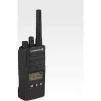
| Product Type | Professional two-way radio |
| Brand | Zebra (formerly Motorola Solutions) |
| Model | XT420 |
| Dimensions (approx.) | 130 x 60 x 35 mm (with standard battery) |
| Weight (approx.) | 250 g (with standard Li-Ion battery) |
| Power supply | Rechargeable lithium-ion (Li-Ion) battery: PMNN4434_R (standard) or PMNN4453_R (high capacity) |
| Battery life | Up to 18 hours in standard use (depending on battery) |
| Channels | 16 programmable channels |
| Frequencies | UHF or VHF band depending on version (programmable via CPS software) |
| Range | Up to 9 km in open terrain; up to 13 floors indoors |
| Main functions | Two-way communication, channel selection, monitor, quiet listening, frequency/privacy code programming, auto scan, VOX/iVOX mode |
| LED indicator | Battery status, receive/transmit, busy channel, errors |
| Programmable buttons | 2 side buttons (SB1 and SB2) configurable via CPS software |
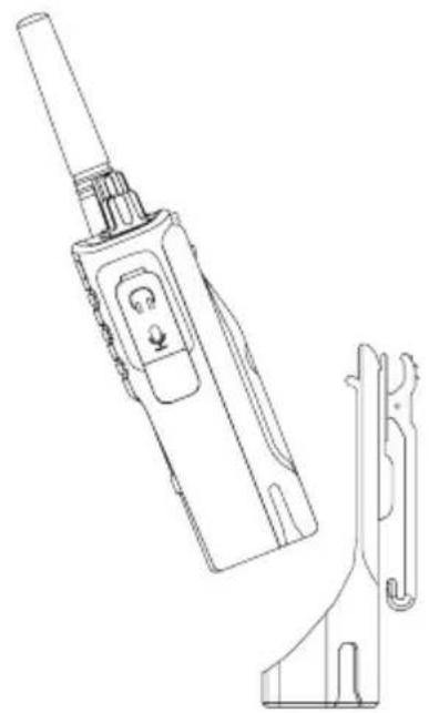
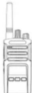
| Antenna | Integrated, non-removable |
| Microphone | Integrated, with Push-To-Talk (PTT) button |
| Charger | Single-unit drop-in charger (included); charges only Motorola approved batteries |
| Operating temperature | -20°C to +60°C |
| Maintenance and cleaning | Damp soft cloth; do not immerse in water; do not use alcohol or detergents |
| Safety | Professional use; comply with FCC/ICNIRP guidelines; use only approved accessories |
| Spare parts and repairability | Battery, charger, power adapter; repair by authorized Motorola representative; charger not user-serviceable |
| General information | User manual available in multiple languages; programming via CPS software (sold separately); complies with professional standards |
Frequently Asked Questions - XT420 ZEBRA
User questions about XT420 ZEBRA
0 question about this device. Answer the ones you know or ask your own.
Ask a new question about this device
Download the instructions for your Radio in PDF format for free! Find your manual XT420 - ZEBRA and take your electronic device back in hand. On this page are published all the documents necessary for the use of your device. XT420 by ZEBRA.
USER MANUAL XT420 ZEBRA
XT420 Non-Display model

CONTENTS
Contents. 1
Safety 2
Batteries and Chargers Safety Information 3
Operational Safety Guidelines. 3
Radio Overview 4
Parts Of The Radio 4
On/Off/Volume Knob. 5
Channel Selector Knob. 5
Microphone 5
Antenna. 5
LED Indicator 5
Side Buttons 5
Batteries and Chargers. 6
Installing the Lithium-Ion (Li-Ion) Battery 6
Removing the Lithium-Ion (Li-Ion) Battery 6
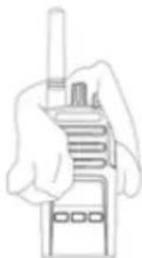
Holster. 6
Power Supply, Adaptors and Drop-in Tray Charger ..7
Charging with the Drop-in Tray Single Unit Charger. .8
Charging a Standard Battery 8
Drop-in Tray Single Unit Charger LED Indicators . . . .9
Getting Started 10
Turning Radio ON/OFF 10
Adjusting Volume 10
Selecting A Channel 10
Talking And Monitoring 10
Receiving A Call 10
Talk Range 11
Reset To Factory Defaults 13
Programming Features 14
Programming Mode 14
CPS (Computer Programming Software). 14
Use And Care 16
SAFETY
PRODUCT SAFETY AND RF EXPOSURE COMPLIANCE

Before using this product, read the operating instructions and RF energy awareness information contained in the Product Safety and RF Exposure booklet enclosed with your radio.
ATTENTION!
This radio is restricted to occupational use only to satisfy ICNIRP/FCC RF energy exposure requirements.
For a list of Motorola-approved antennas, batteries, and other accessories, visit the following website which lists approved accessories:
http://www.motorolasolutions.com
BATTERIES AND CHARGERS SAFETY INFORMATION
This document contains important safety and operating instructions. Read these instructions carefully and save them for future reference.
Before using the battery charger, read all the instructions and cautionary markings on
the charger,
the battery, and
- the radio using the battery
1. To reduce risk of injury, charge only the rechargeable Motorola-authorized batteries. Other batteries may explode, causing personal injury and damage.
2. Use of accessories not recommended by Motorola may result in risk of fire, electric shock, or injury.
3. To reduce risk of damage to the electric plug and cord, pull by the plug rather than the cord when disconnecting the charger.
4. An extension cord should not be used unless absolutely necessary. Use of an improper extension cord could result in risk of fire and electric shock. If an extension cord must be used, make sure that the cord size is 18AWG for lengths up to 6.5 feet (2.0m) and 16AWG for lengths up to 9.8 feet (3.0m) .
- To reduce risk of fire, electric shock, or injury, do not operate the charger if it has been broken or damaged in any way. Take it to a qualified Motorola service representative.
- Do not disassemble the charger; it is not repairable and replacement parts are not available. Disassembly of the charger may result in risk of electrical shock or fire.
- To reduce risk of electric shock, unplug the charger from the AC outlet before attempting any maintenance or cleaning
OPERATIONAL SAFETY GUIDELINES
- Turn the radio OFF when charging battery.
- The charger is not suitable for outdoor use. Use only in dry locations/conditions.
- Connect charger only to an appropriately fused and wired supply of the correct voltage (as specified on the product).
- Disconnect charger from line voltage by removing main plug.
- The outlet to which this equipment is connected should be nearby and easily accessible.
Maximum ambient temperature around the power supply equipment must not exceed 40^ (104^) - Make sure that the cord is located where it will not be stepped on, tripped over, or subjected to water, damage, or stress.
RADIO OVERVIEW
RADIO OVERVIEW
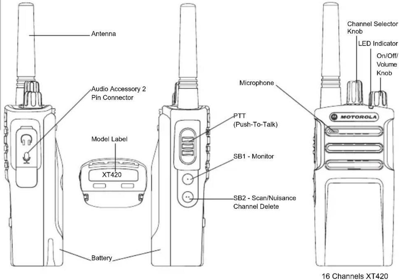
PARTS OF THE RADIO
On/Off/Volume Knob
Used to turn the radio ON or OFF and to adjust the radio's volume.
Channel Selector Knob
Used to switch the radio to different channels.
Microphone
Speaks clearly into the microphone when sending a message.
Antenna
The radio's antenna is non-removable.
LED Indicator
Used to give battery status, power-up status, radio call information and scan status.
Side Buttons
Push-to-Talk (PTT) Button
- Press and hold down this button to talk, release it to listen.
Side Button 1 (SB1)
- The Side Button 1 is a general button that can be configured by the Computer Programming Software - CPS. The default setting of SB1 is 'Monitor'.
Side Button 2 (SB2)
- The Side Button 2 is a general button that can be configured by the CPS. The SB2 default setting is 'Scan/Nuisance Channel Delete'.
BATTERIES AND CHARGERS
Installing the Lithium-Ion (Li-Ion) Battery
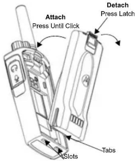
- Turn OFF the radio.
- With the Motorola logo facing up on the battery pack, insert the tabs at the bottom of the battery with the slots at the bottom of the radio's body.
- Press down on the battery, top first, towards the radio until a click is heard.
Removing the Lithium-Ion (Li-Ion) Battery
- Turn OFF the radio.
- Push down the battery latch and hold it depressed while removing the battery.
- Pull the battery away from the radio.
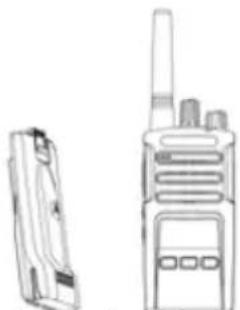
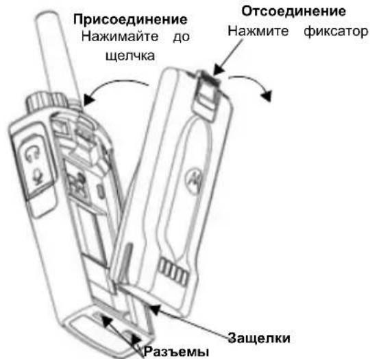
Holster
XT420 and XT420 will be coming with Holster instead of Belt Clip to improve the wearability.
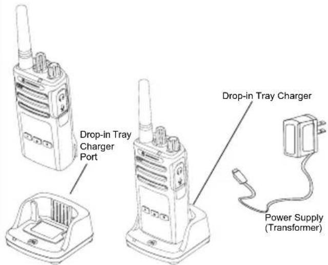
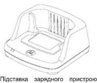
Power Supply, Adaptors and Drop-in Tray Charger
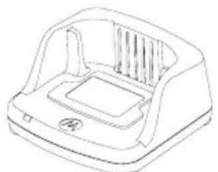
Drop-in Tray Charger
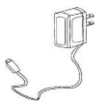
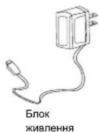
Power Supply
Your radio comes with one Drop-in Tray Charger, one Power Supply (also known as Transformer) and a set of adaptors.
Your Power Supply is capable of switching to suit any of the adaptors that comes with your radio package.
The Adaptor you install depends on the region you're located.
Once you have identified the Adaptor that matches your electrical outlet, proceed to install it as follows:
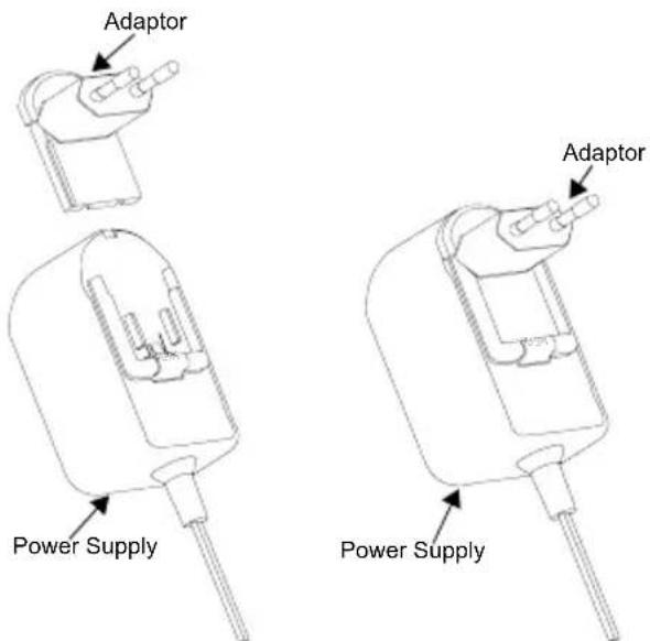
- Slide down the Adaptor grooves into the Power Supply until it snaps into place.
- Slide the Adaptor upward to remove.
Note: The adaptor shown in the pictures are for illustration purposes only. The adaptor you install may be different.
When acquiring additional Charger or Power Supply, make sure you have the similar Drop-in Tray Charger and Power Supply set.
Charging with the Drop-in Tray Single Unit Charger
- Place the Drop-in Tray Single Unit Charger on a flat surface.
- Insert the connector of the Power Supply into the port on the side of the Drop-in Tray Single Unit Charger.
- Plug the AC Adaptor into a power outlet.
- Insert the radio into the Drop-in Tray Single Unit Charger with the radio facing the front, as shown.
Note: When charging a battery attached to a radio, turn the radio OFF to ensure a full charge. See "Operational Safety Guidelines" on page 3 for more information.
Charging a Standard Battery
The Drop-in Tray Single Unit Charger is designed to charge either the battery (with the radio or with radio and holster on) or a standalone battery.
Table 1: Motorola Authorized Batteries
| Part Number Description | |
| PMNN4434_R Standard Li-Ion Battery | |
| PMNN4453_R High Capacity Li-Ion Battery |
Drop-in Tray Single Unit Charger LED Indicators
Table 2: Charger LED Indicator
| Status LED Status Comments | ||
| Power On Green for approx. 1 | sec | |
| Charging Steady red | ||
| Charge Complete Steady green | ||
| Battery Fault (*) | Red fast flash | |
| Waiting to charge (**) | Amber slow flash | |
| Battery Level Status | Flash red 1 time | Battery low |
| Flash amber 2 times | Battery medium | |
| Flash green 3 times | Battery high | |
() Normally, re-positioning the battery pack will correct this issue.
(^*) Battery temperature is too warm or too cold or wrong power voltage is being used.
If there is NO LED indication:
- Check if the radio with battery, or the battery alone, is inserted correctly.
- Ensure that the power supply cable is securely plugged into the charger socket.
- Confirm that the battery being used with the radio is listed in Table 1.
GETTING STARTED
For the following explanations, refer to "Parts Of The Radio" on page 4 of the user guide.
To turn ON the radio, rotate the ON/OFF/Volume Knob clockwise. The radio plays one of the following:
- Power up tone and channel number announcement, or
- Battery level and channel number announcements, or
- Silent (Audible tones disabled)
The LED blinks red briefly.
To turn the radio OFF, rotate the ON/OFF/Volume Knob countercase until you hear a 'click' and the radio LED indicator turns OFF.
ADJUSTING VOLUME
Turn the ON/OFF/Volume Knob clockwise to increase the volume, or counterclockwise to decrease the volume.
Note: Do not hold the radio too close to the ear when it is at a high volume setting or when adjusting the volume setting.
SELECTING A CHANNEL
To select a channel, rotate the Channel Selector Knob and select the desired channel number.
Program each channel separately. Each channel has its own Frequency, Interference Eliminator Code and Scan Settings.
TALKING AND MONITORING
It is important to monitor for traffic before transmitting to avoid 'talking over' someone who is already transmitting. To monitor, press and hold the SB1(*) button for 2 to 3 seconds to access channel traffic. If no activity is present, you will hear 'static'. To release, press the SB1 button again. Once channel traffic has cleared, proceed with your call by pressing the PTT button. When transmitting, the radio LED will blink red every 3 seconds.
(*) This assumes SB1 button has not been programmed for a different mode.
RECEIVING A CALL
- Select a channel by rotating the Channel Selector Knob until you reach the desired channel.
- Make sure the PTT button is released and listen for voice activity.
- The LED Indicator blinks RED while the radio is receiving a call.
- To respond, hold the radio vertically 1 to 2 inches (2.5 to 5cm ) from mouth. Press the PTT button to talk; release it to listen.
Note: Please note that when radio is receiving or transmitting, LED is always RED.
Note: In order to listen to all activity on a current channel, short press the SB1 button to set the CTCSS/DPL code to 0. This feature is called CTCSS/DPL Defeat (Squelch set to SILENT).
TALK RANGE
XT Series radios have been designed to maximize performance and improve transmission range in the field. It is recommended that you do no use the radios closer than 1.5 meters apart, to avoid interference. XT420 coverage is 16.250 square meters, 13 floors and 9 KM in flat areas. Talk range depends on the terrain. It will be affected by concrete structures, heavy foliage and by operating radios indoors or in vehicles. Optimal range occurs in flat, open areas with up to 9 kilometers of coverage. Medium range occurs when buildings and trees are in the way. Minimal range occurs when dense foliage and mountains obstruct the communication path. To establish a proper two-way communication, the Channel, Frequency and Interference Eliminator Codes must be the same on both radios. This depends on the stored profile that has been preprogrammed on the radio:
- Channel: Current channel that the radio is using, depending upon radio model.
- Frequency: The frequency the radio uses to transmit/ receive.
- Interference Eliminator Code: These codes help minimize interference by providing a choice of code combinations.
- Scramble Code: Codes that make the transmissions sound garbled to anyone listening who is not set to that specific code.
- Bandwidth: Some frequencies have selectable channel spacing, which must match other radios for optimum audio quality.
For details of how to set up frequencies and CTCSS/DPL codes in the channels, refer to "Programming Features" on page 14
Note: Interference Eliminator Codes are referred also as CTCSS/DPL codes or PL/DPL codes
RADIO LED INDICATORS
| RADIO STATUS LED INDICATION | |
| Channel Busy Solid Orange | |
| Cloning Mode Two Orange Heartbeats | |
| Cloning In Progress Solid Orange | |
| Fatal Error at Power up | One Green Blink, One Orange Blink, One Green Blink, then repeat for 4 seconds |
| Low Battery Orange Hearbeat | |
| Low Battery Shutdown Fast Orange | Heartbeat |
| Monitor LED is OFF | |
| Power-Up Solid Red for 2 seconds | |
| 'Idle' Programming Mode /Channel Mode | Green Heartbeat |
| Scan Mode Fast Red Heartbeat | |
| Transmit (Tx)/Receive (RX) Solid Red | |
| Transmit in Low Power Select Solid | Orange |
| VOX/iVOX Mode Double Red Heartbeats | |
Reset To Factory Defaults
Reset To Factory Defaults will set back all radio features to the original factory default settings. To do so, press the PTT, SB1 and SB2 button simultaneously while turning ON the radio until you hear a high tone chirp beep.
PROGRAMMING FEATURES
To easily program all the features in your radio, it is recommended to use the CPS Kit which includes the Programming Cable, CPS and accessories sections.
Programming Mode
- Programming Mode is special radio mode that allows you to program basic radio's features by using the radio's panel programming.
When the radio is set to Programming Mode, you are able to read and modify three features:
- Frequencies,
- Codes (CTCSS/DPL) and,
- Auto-scan.
The Programming Frequencies feature allows you to select frequencies for each channel.
The Interference Eliminator Code (CTCSS/DPL) helps minimize interference by providing you with a choice of code combinations that filter out static, noise, and unwanted messages.
The Auto Scan feature allows you to set a particular channel to automatically enable scan each time you switch to that channel (you will not need to press any button to start scanning).
For more details in programming features please go to http://www.motorolasolutions.com to download the full version of the XT420/XT460 User Guide.
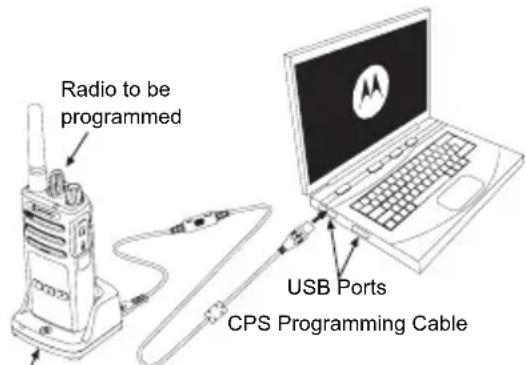
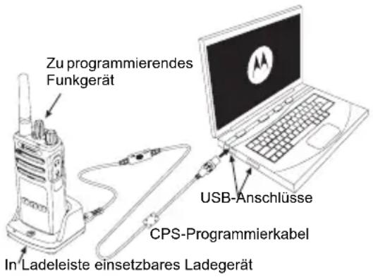
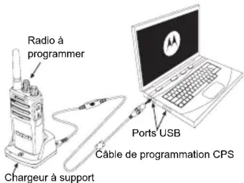
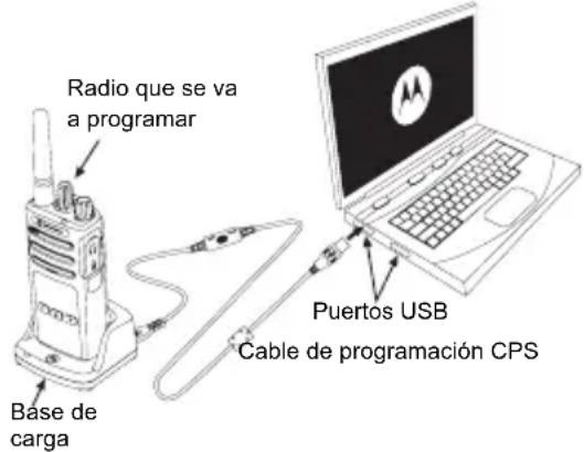
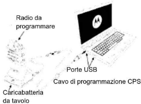
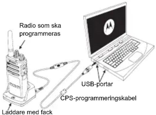
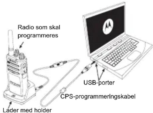
CPS (COMPUTER PROGRAMMING SOFTWARE)
Drop-in
Charger Tray
The easiest way to program or change features in your radio is by using the Computer Programming Software (CPS) and the CPS Programming Cable ^(*) .
The CPS allows the user to program frequencies, PL/DPL codes as well as other features such as: Time-out Timer, Scan List, Call Tones, Scramble, Reverse Burst, etc. CPS is a very useful tool as it can lock the frontpanel radio programming or restrict any specific radio feature to be changed (to avoid preset radio values to be accidentally erased).
It also provides security by giving the option to set up a password for profile radio's management. Please refer to Features Summary Chart Section at the end of the User's Guide for more details.
Note: Features should be enabled by an authorized Motorola Dealer. Contact your Motorola Point of Purchase for details.
Note: (*) CPS Programming Cable is an accessory sold separately. For part number information, refer to the Accessories Section.
See CPS CD for detailed information on CPS.
USE AND CARE

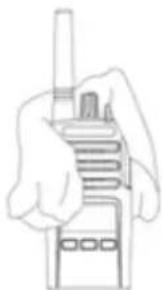
Use a soft damp cloth to clean the exterior

Do not immerse in water Do not use alcohol or
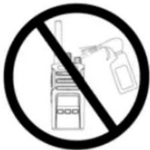
cleaning solutions
If the radio is submerged in water...
Turn radio OFF and remove batteries
Dry with soft cloth Do not use radio until
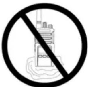
completely dry
INHALT
Push-to-Talk (PTT)-Taste
CPS (COMPUTER PROGRAMMING SOFTWARE)
CPS (Computer Programming Software). 14
Bouton PTT (Push-to-Talk)
MISE SOUS TENSION/HORS TENSION DE LA RADIO
RéCEPTION D'UN APPEL
CPS (COMPUTER PROGRAMMING SOFTWARE)
CPS (Computer Programming Software). 14
CPS (COMPUTER PROGRAMMING SOFTWARE)
Software CPS (Computer Programming Software) 14
pulsante PTT (Push-to-Talk)
SOFTWARE CPS (COMPUTER PROGRAMMING SOFTWARE)
Knop Push-to-Talk (PTT)
CPS (COMPUTERPROGRAMMEERSOFTWARE)

JUSTERING AF LYDSTYRKEN
Drej taend-/sluk-/lydstyrkeknappen med uret for at skrue op for lyden og mod uret for at skrue ned for lyden.
CPS (Computer Programming Software). 14
CPS (COMPUTER PROGRAMMING SOFTWARE)
CPS (Computer Programming Software). 14
PRODUKTSIKKERHET OG RF EKSPONERINGSSAMSVAR

Obs!
För du tar i bruk dette produktet, má du lese braksanvisningen og informasjonen om RF-energi, som du finner i heftet om Produktsikkerhet og RF-ekspondering som fulgte med radioen.
OBS!
PTT-knapp (Push-to-Talk, trykk for a snakke)
CPS (COMPUTER PROGRAMMING SOFTWARE)
Lityum-Iyon (Li-Ion) Bataryayi QiKarma 6
Tutucu. 6
Lityum-iyon (Li-Ion) Bataryayi Takma
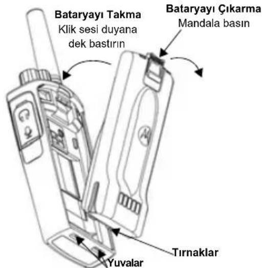
Lityum-lyon (Li-Ion) Bataryayi Cikarma
- Telsizi KAPATIN.
- Bataryayi cikarirken batarya mandalini bastirarak asagidogru itin.
- Batayayi telsizden cikarin.
Tutucu
Przycisk Push-to-Talk (PTT)
Puyka Bn6opy KaHanib 5
Mikpooh .5
AHTeHa 5
CbiTIOIOHN iHnKaTOp. .5
BiHki KhoNkn 5
AkymyjIopu Ta 3apJHi npncTpoi 6
BctaHOBnHnna nii-nioHHoro (Li-Ion) akymyIaTopa..6
BnMaHHraIiHIOHOrO(Li-Ion)akymyIaTopa. . . .6
Yoxon 6
BLOKKMBHHe, aanTepn Ta 3apAHH npncpti 3 niDCTaBKOIO .7
3apdkaHH 3a DOnOMoroO ODNHomichoro 3apdHoro npictpoO 3 niDcTaBkoHO .8
3apdkaHHn akymyIaTopa cTaNdapTHoI eMHOCTI .8
CbiTnoiOdiHi iHnKaTopn NiDCTaBKn OndHomichoro 3apAHHoro npncTropo. .9
PiIroTobka do po6oTu 10
BMUKAHHRAUMIKAHHApaioctaunii.10
PeryIIOBaHHra ryHocTi 10
Bn6ip padiokaHany 10
06mH nobIDOMJIeHHaMn Ta MoHiTopuHr 10
PpHOM BnKnKy 10
Puyka Bn60py KaHaJIIB
BnKOpNCTOByETbCn nna nepemkaHHKaHaJIb paioctaHii.
Mikpocph
Pn npepeda niobidomJIeHb roBopitb y MikofoH.
AHTeHa
AHTeHa paioctaHcii He3HIMHOIO.
CbitIopioDHH iHdkaTop
Pn3NaueHnn IJy BiO6paKeHHcTaHy aKymIaTopa, cTahy paIOCTaHcII (YbIMKHeHH/BIMKHeHH), cTahy paIOBKNkky Ta cTahy cKaHyBaHH.
BiHi KhoNk
Tahzehma PTT (Push-to-Talk - an. «Hamuchu-ma-foopu»)
-Дя nepedaichi nobiDomneHH HaTNCiTB Ta yTpmyTe TaHReHTy,дя npocnyxOByBaHH -BiNyctiB.
BiHa KhoNka 1 (SB1)
- BiuHa KhoNka 1 e KhoNko 3araIbHoro npn3HaueHHra Ka HanaaTobByeTbcra 3a DonomorOIO KOMN'ToTePHoro npoRpaMHOrO 3a6e3neueHHa CPS. HanaaTyBaHHra dnn KhoNk SB1 3a 3aMOBvBaHHm - «MoHiTopnHr».
BiHa KhoNka 2 (SB2)
BiuHa KhoNka 2e KhoNko 3aRaIbHoro npu3HaueHHra Ka HalaustobyeTbcra 3a Donomoroi P3 CPS.HalaWtyBaHHn DnK Honk S23a3amOBuyBaHHm-«CkaHyBaHHr/BuaJaeHHn He6axaHnx KaHaJIb
AKUMYJIATOPN TA 3APYIHI IPIPCTPOI
BcTaHOBJIeHHa NiTiH-IOHOrO (Li-Ion) akymyIaTopa
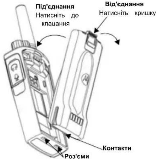
1.BIMKHTb paioctaHIO.
2. Po3auyte akymyTOpHn BiDcIK norotunom Motorola Doropu Ta 3ictabTe KOHTKn B HxKHi yactHi akymyTota i3 KOHTAKTMn BHn3y Ha Kopnyci paiaoctaHii.
3. NounaOH 3 BepxHbO r KpaIO,do KnaaHa Hn npTnCHITb akmyJrTO paoCTAHii.
BnMaHnI niTi-iOHHoro (Li-Ion) akymyIaTopa
1.BIMKHITb paioctauio.
2.3cHbTe KPNUky aKyMyJrTopa BHN3.
3. Tpmaou Kpuuky npntnchyto, BHTaHt b akymyTOp i3 paioctauii.
Yoxon
XT420 ta XT460 BUNyCKaTMybC8 i3 0xJOM 3amictb norochoi Klinncn Dn6inbKoMdoptHoro HocHHA.

Блok КИВLEHЯ,адаNTepиТа 3apянй npстpii 3 NiДСТАВКОЮ
IIO KOMNNEKty paioctaHuiBXOINTb OINH 3apnHnn pncptpi i3 IOTKOM DnBCTaBnHHn PpnaDy, OINH 6nOK XNBHeHH (TAKOX NOro Ha3nBaHTb TpaHCfOpMaTOPOM) Ta H6ip aanTepiB.
MoxnBicTb nepemKanHna 6IOKy XMBHeHHa DO3BOJRE BIKOpNCTOByBaTu NOrO 3 6yDb-RAKM aadantepom i3 KOMJIeKTy NOCTaUaHHa.
Bn6ip aanTepe 3aEnKntb BID perioHy, B yKOMy BnKOpncTOByeTbcn npncpti.
Bn3NaUHbui, kni aanTep nixOaNTb IJr po3eTKn eNeKtpomepexi, BnKOHaIte BCtAHOBJIeHHra, kONuCAHO dani:

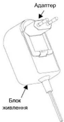
BCTABTe na3n aanTepa y 6nok XNBHeHH i nocyHbTe aanTep yHn3, 06 BiH i3 KnaaHHaM BCTaHOBBcRa Ha Micui.
Uo6 BnHrtn aadTep, 3cyhTe Ioro Bropy.
Ппмітka. АдалТер, пokазанн Ha ManIOHkax, ВИКОPGСТАно Лше ДЯ demOHCTpaцг. АдалТер, ркий NotpiбHo 6уde BCTaHOBHTN, може 6уTN iHWM.
Knyuoyn doaTkoBni 3apdHnn npncptpi a6o 6noK XNBHeHHN, nepeKOHaHTecra, 0O BOHN iDeHTnuHi HaBHOMy ODHOMICHOMY 3apdHOMy npncptpo 3 niDCTabKOIO Ta 6NoKy XNBJIeHHN.
3apxkanna 3a donomoro oHomicho 3apndoro npncpto 3 ndTabkoio
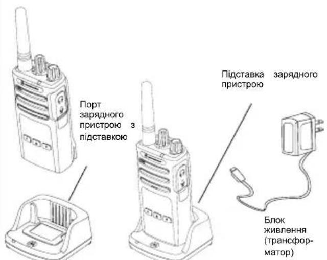
- NocTabe OndHomicn 3apJHn npncpti 3 niDcTabkoHO Ha pibHy NOBepxHIO.
- BCTABTe po3'em 6nOKy kHNEnHbBnENTp36OKyHa nDCTabU ODHOMICHORO 3apAHorO npNCtPOHO.
3.ПдкнчыадаNTep 3MiHOrO CTpyMy Do po3eTKeIeKtpomepeksi. - NocTaBte paiaocTahuO y niCTaBky nIbBOHO CTopoHOHO nepeHboi naHeni 3apAHoro npicToIO, k NOKa3aHO Ha MaIOHky.
CunHan yBIMKHeHH npnCTpoTa oronoeHH Homepa KaHany
OronouenHH pIBH zapny aymyIyTopa Ta HOMepa KaHany
Be33ByHn (ayioCnHaHn He BiTbOPHOtbcra
CbitnoioiDnH iDnKaTOp DeaKu Yac 6nMaTMe UepBOHm.
IooB BmKHytn paioctanio, nobepHtby pyky YBIMK./ BIMK./TpyHicTB) npOTn rOINHHKOoi CTpiKN do KlaaHnn, pni cboMy CBITNOIOHN iHNkATOp BmKHeTbCra.
PERYJIIOBAHNNI IYUHOCTI
NobepTaIe pykY «YBIMK./BMK./rhyHicTb» 3a roHHNKOBIO CTpiIKO, 06 36iNbWHTn rhyHicTb, Ta npOTn roHHNKOBoi CTpiIKN, 06 3MeHwNTn II.
PpIMtKa. Pn niiBnueHri ryHocTi Ta niD yac peryIIOBaHHra ryHocTi He TpMaIte paioctaHciu HADTo 6bn3bko Byxa.
BnBIP PADIOKAHAJIY
I06Bn6paTn KaHaJI, NOBepTaIe pyUky Bn6Opy KaHaJIb, DOKN He 3HaJDeTe nOTpiHNI.
KoHnn KaHn nporpamyeTbCg OKPemO. nKaKHO 1HaNBy BCTAHOBIOEtBCB CBOA cactota, KOD Wym03arJTyUeHH Ta HanaHTyBaHHc KaHyBaHH
OBMIH IOBIIDOMJIENHHaMNA MOHITOPINH
Baxnbo npoBeCTmoHITOpHr efpipy nepeq noaTkom po60tn, 06 nepekoHaTncs, 0BaWe cninkyBaHH He haklaadatmMetbcra Ha nepeauy iHwOi paioctanii.
Дя nepeBipkn HABHOCt Tpaikny Ha cbyOMy KaHani NaTnCHiB Ta yTPmMyTe KhoNky SB1(*) npotraom 2-3 ceKHyd. 3a BiCyTHocTi 6yd-b-AKOi AKTNBHOCTi 6yde ChyTHO CTaTuHi 3abAn. HATnCHiB KhONky SB1 ue pa3 Ta BiNyctiB II, 06 3aBepuHTMoHITOpHHr. 3a BiCyTHocTi Tpaiky Ha cbyOMy KaHani BIKOHai Te BIKNIK, HATnCHyBwn TaHReHry PTT.Пд.Yac nepeDaChi CBiTNOIOHm iHdNKatop paoCTaHcii 6yde 6bIMaTIu YepBOHM KOKHI 3ceKHyd.
(*) 3a yMOBn, IO KHOJky SB1 He 6yNo nepenporpamObaHo Ha iHsy fYHKUIO.
ПРИСМ BИКЛИКУ
- Bn6epiB kaHJI, nobepTaOHy pyKy Bn6Opy kaHaniB,doKn He 3NaJDeTe noTpi6HnI.
- IpekeohaiTeca, 10 taHReHTa PTT He HATnCHyTa, Ta npocnyxaTe roNOCOBy AKTINBHCtB.
3.Пд Ус пиюм CBITIOIDHIN IHNKATOP 6JIMae YepBOHIM KONbOpOM.
4. Ⅲo6 npnHnTN BnKnK, TpMaTe paiaocTaHIOBepTKaJIbHO Ha BiCTahi 2,5-5 cm BiD ry6. Ⅲo6 nepeDaTn
noBIDOMJIeHHHaNTNCIb TaHReHTy PTT, Ta BiNcyTITb II, 06 npocnyatn BiNNoBIB.
Ipnitka. 3BepHItb ybar, 10 niD qac npnomy a6o nepeaqi Hdkatop paioctahui noCTiHo Cbitntbcr YepBOHM KObnOpom.
Ппмітka. Ⅲб порсунхати BCIO AKTNBHCtby y cibomy kahanii, 3. KopoTko HATNCiTB KONKY SB1 ta BCTaHOBiTb Дя КODY CTCSS/DPL 3naeHnR «O». LЯ Функця Ha3nBaetbcr «BiДmHa CTCSS/DPL» (3aIryuweHnR 3abd BiKlouaTebcr).
ДАльбИСТБ BИКЛИКУ
MeTOO CTBOpENHpaionpncTpoIB cepii XT e
MaKcImaJIbHe NOKpaUeHHN ekCnIyatauiHnx
XapakTePepNCtNK Ta nIDBVuEHHN daIbHOCTi 3B'3ky Ha
BiIKpnTomY npocToPi.PekomeHDoBaHa BiIcTaHb MIX
paioJnpNCTporMn DnIy YHNKHeHH B3aEMHx NepeWKOd
MaEc cTAHOBHTn He MeHwe 1,5 MeTpA. Padiyc dIYT420
ckNaJaAc 16 250 Kb.M., 13 nobepxib afo 9 km Ha pIBHi
MICueBOCTi.
ДальнICTb 38'я3ky 3aIeJXITb BID peJIbeCyMiueBoCTi.Ha
ДальнICTb 38'3ky BnINBaTakOK HaABHicTB TaKnx
nepeWkoD,ЯбБToHHI KOHcTpKyii,prChI 3eNeHi
HacadJxehnA,a TakoK BnKOpNCTaHHa paIOCTaHHy
npmIuHeHHI a6o TpaHCnopti. ONTMaIbHN paDiYc di
ctAHOBHTb 9 KM Ha pIBHi BIDkpNTi MiueBoCTi.3a
HaABHoCTi 6ydIBeB Ta DepeB Ha 7JMy CnHaJy
ДальнICTb 3B'3ky 6yde cepedhBOIO.DaIbHicTB 6yde
MinImaIbHOIO,AKUO Ha 7JMy nepeDaHi TpannaIObC
rycti 3eNeHi HacadJxehnA ab6 ropn.ДЯ 3a6e3neuHnra
RikCHOrO 3B'3ky MIX DbOMa PaioCTaHciMn O6nDbA
PpInaDN MaOTb 6yTN HanaSTobAhI Ha OdNH i Toi Camn
KaHaI, YactOTy Ta KOni Shymo3arLyWeHHN.ДЯ cboRo Ha
paioctanii cnid 3a3dneri b 3anporpamybTu Ta 36epertn HanaHTyBaHHa:
- KaHAn: nOToUHH KAHAn, IIO BnKOpNCtOByETbcra paiaocTaHcHcEO (B 3aIeXHOCTi BiD MoDeni).
- Yactota: yactota, ha kii BedeTbC npiHOM Ta nepeadaa.
- Kod wymo3arnyweHHn: nidi6paBwN KOmbiauio KoDIB, MOxHa 3Hn3NTPiBeHb 3aBaJd.
- Kod cKpem6JIOBauHHa: zu KoDi BnKOpNCOTByOITcBcA JnA CNOTBOpEHH 3ByKy nId Yac nepeaHi, OTKe NObIDOMNeHHa MOxHa 3po3yMitu TlbykN 3a HnABHOCTi BiINOBiDHorO
- Wipnha cmyr: nIeJeKx Yactot icHy e Haibp KaHaNIB, kI MaIOb cnBnaDAtu y DBox paioctaHix x dIy 3a6e3 kichoro paioo6MiHy.
Дokлади inhtrpykii lo do HanaStyBaHnHa YacToT Ta KODCTCSS/DPL nra KaHJIIB nB. y po3diIi «PeximnporpamyBaHHa» Ha cTOp. 14
ПримИк. Кд Учмоаглуш�н Ha3иBaIOТьс RAKOK KODAMI CTCSS/DPL a60 KoДам PL/DPL
CBITJIOIOHI INIKATOPN PAIOCTAHII
KOMTIOTEPHE IPOPTPAMHE 3A6E3NEUEHH CPS
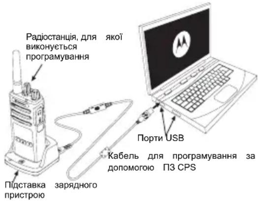
Haipoctiuim cnocobm nporpamyBaHHa6o 3miHn i fyHKuii paioctaHciE BIKOpncTahnn KOMN'IOTePHoro nporpamHoro 3abe3neueHHa (CPS) ta Ka6eJn nporpamyBaHHa CPS(*)
13a donomoro nporpamhoro 3abe3neueHHn CPS moKHa nporpamyBaTN uactOTn, kOu PL/DPL, a taKoK iHwi yHKui, a came: TaMep o6MeKeHHy acy nepeaqi, nepeiik cKaHyBaHH, ToHaJIbHi BKNJIKNi, CkPem6IIOBAHH, yHKiuo «Reverse Burst» ta iHwe. CPS e dyJke 3pyHnM
IHCtpymeHTOM, 30 Do3B0JAE 3abOpOHn nporpaMyBaHHa 3 nepeHbOi naHeJI a6o 6mExHTM MoKlnBOcTi 3MiHN 6yNb-RAIO Bka3aHOi fYHKci (IIN PA nonepedKeHHBnAkoBOr BnuJaJIeHHN nonepedHbo 3anporpamOBaHnx HanaSTyBaHb).
Okpim TOrO, BOHO NiIbNUIyepiBHeH 6e3NeKn, Do3BOJIaOuH BCTaHOBIIOBaTn napoiI dIpyoΦiIIO HanaWtYBaHb paioctaHcii. DOKnAHIwI yIhOpMaIIO MOxHa OtpMaTn y po3di I《TaBNIUa FyHKui》y KINCI UboRIO NociHnka KopncTyBaHa.
Примитka.Функц MaOTb 6yTN aKTINBOaHI cepTnΦIKOBaHIM ToproBm npedCTaBnKOM KOMnaHII Motorola.3a IHΦopMaJIeIO 3BepTaITeCЯ Do MlueBoI ToKN npOdaKy KomnaiH Motorola.
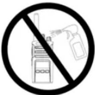
He BnKOpncToBvIe cnIrt a6o MNoOci 3ac06n
Kaio do paioctanii notpanna Boda...

BIMKHiTb BNIIMiTb
paioctaunio akymyIaTOpn
PpOpiTb cyXo TKaHnHO

He KopnctyntecpaiaocTaHueo, DOKN BOHa NOBHicTIO He BnCOxHe
YkpaHcbska
COДЕРЖAHNE
CoepeKaHne 1
Be3onachocTb 2
Hopmaqna no Texnke 6e3onacHOCTn npu
06paueHn c aKKymyTOpamn 3apAHybIMN
yctpoNCTBaMn 3
Yka3aHnno 6e3oNaChoi KcNpyatau.4
O63op paIIOCTaHcH.. 5
BheuHn BUD n opraHbI ynpabLeHHra 5
PeryIaTOp BkN./BbIKN./PomKocTb .6
Puyka BbIbopa KaHanoB 6
MinkpofoH 6
AHTehha 6
CBeToIIOIOHbI INDnKaTOp. 6
Bokobbie KhoNKn 6
AkkymyIaTOpbI n 3apdHbIe ycTpoNcTba. 7
YcTaHOBKa NITn-NOHOro AKKMyJrTopa .7
I3BJIeueHHe JInTHN-IOHHOro AKKMyJrToPA. 7
DepkataJIb epnneHem Ha peMeHb 7
BLOK NITAHIN, aadTepbN BCTpoEHHOE B
noCTaBky 3apdHoe yctpoNCTBO .8
3apka c nCnoJb3ObaHnEM BCTpoeHHoro B
noctabky 3apnHOrO yctpoCTBa.9
3apka cTaNdapTHoro aKKymyIaTopa. .9
CBeToIONoHbIe HnDnKaTOpbl 3apJdHOrO yCTpoiCTBa
Ha noDCTaBKe 10
Hauano pa6oTbl. 11
BkIIOueHne/BBKIOueHne paIOocTaHcnn 11
Perynipobka rpomkoctn 11
BbIbOp kaHana. 11
Pa3roBop mOHTOpnHr 11
Ipnem Bb3Oba. 11
TbHOCTb CBA3N 12
C6pocdo 3aBoDcKnx HacTpoeK 14
HKUINI pporpaMMnpoBaHn. 15
PexkIM nporpaMMnpoBaHnI 15
CPS (komnbpoephoe IO dny nporpaMMnpoBaHna) . 15
IcnoIb3OBAHne u yxo
БЕЗПАСНСТБ
БЕЗПАСНСТБ ПОДУКТА И COOTBETCTBNE TPEБОВАнЯМ NO BO3ДЕИCTВИО PAДNOЧАCTOTHОГО ИЗЛУЧЕНИА

Ipepe nauanom nCnoJb3ObaHnnaDHHoro npoodykTa BHNMaTeNbHO npoptyaTe HCTpyKuIN NO 3KcNpyatauIN 6yKJeT NO 6e3oNaChocTN npoodykTa COOTBeTCTBnIO Tpe6oBaHnM NO BO3DeiCTBnIO paNoocToTHoro N3nyehn, pnploKeHHbIK BaWei paNoocTaHcN,B KOTOpOM coepKHTcN INΦopMaZrO HaNvHn paNoocToTHoro N3nyehn.
BHIMAHNE!
PerylaTop BkI./BbIKI./PomKocTb
IcnoJIb3yETcA DnB KKnIOueHn Nn BblKIOUeHn paDIOCTaHcNn I DnpeYynIpOBKn rPOMKOCTn.
Pyka BbI6opa KaHaJIOB
IcnoJIb3yETcI dIJI nepeKIOUeHnM MeKdy pa3JIMuHbIMn KaHaIaAMPi aDIOCTaHcUN.
MnKpOoH
Pn Otnpabke coo6eHna Heo6xOJMo roBOpNTb B MKNpOFOH qETKO n pa36opUBO.
AHTeHHa
AHTeHHa paAnocTaHcHn He CHImaeTcR.
CBeToDnOHDhI NHdNkATOp
NcnoB3yETcIg O6o3HaeyHn COCTOHN AKKMyJrTopa, BKNIOUeHn, INΦOpMaUN O Bbl3OBe N COCTOHN CkAHIpOBAHN.
БOKOBbie KHONK
Khonka PTT
Hakmnte u yedejkmbaTe KhONky PTT npa p3roBopa n OTnycnte ee dny npocnyuBaHn.
Бokoea KhoIka 1 (SB1)
- Bokobar Khonka 1 aBnIeTc8 o6u9e KhoNko, KOtopa MoKet 6bItb HacTpOeHa c nOMoUbO KOMNbIOTePHoro IO nI nporpamMnpoBaHna — CPS. HAcTpOko SB1 no yMonHaHIO RaBnIeTc8 "MoHtOpHr".
Bokobar KhoIIka 2 (SB2)
- BOKOBA KONKA 2 ABJAREC O6uei KNHKOJ, KOtopa MoKET 6bITb HAcTpoEHa C NOMOUsIO CPS. No yMOJIHcHNOBA SB2 HAcTpoEHa HaФyHKUHO "CkaHIpOBaTB/YdaIITb KaHAn c nomexoJ".
AKKUMYJIATOPbI N 3APJHbIE YCTPOINCTBA
YcTaHOBka JNTn-NOHORO aKKyMylrTopa
1.BbIKIOuHTe paIIOCTaHcIIO.
2. PacnoonKeTe aKMyJnTOp TAK, YTo6bI NorOtun Motorola 6bln HnpaBnEH BBePx, N BCTabBe Te 3aueKeIN B HnXHei qactn aKKyMnyToppa B pa3beMbI, pacnoJIOKeHHbIe B HnXHei qactn Kopnyca paNIOCTaHcUN.
3. BdaBte akkymyTTop, BepxHIOu cactb, Bkopnyc paNocCTAHm TAK, YTO6bI NocBbUanC HENQK.
N3BJeHHe JNTn-NOHOro aKKyMyJrTopa
1.BbIKIOuHTe paIIOCTaHIO.
2.HaKMTe Ha KcATOp AKKymyIaTopa u ydepXnBaIte er 3TOM NOIOKeHN.
3. BbTaunTe aKKyMnyTOp n3 paAnocTaHnN.
CBeToDnOuHna HnDnKaun OTCyTCTByeT:
- PpOBepe, npaBnIbHO nI paNIOCTaHcIa C aKkMyJrTOpOM nII aKkMyJrTOp OTdJIbHO yCTaHO b 3apAHOy cTPOIcTBO.
- PpOBepe, npaBnIbHO JIN Ka6eN bYcTpoCTBa NODKNIOHcKpa3bemy YcTPOCTBA.
- Y6eHNTecb, YTO aKKMyJrTOp, IcNoIb3yEmbI B yCTpoiCTBe, yka3aH B Ta6n.1.
HauJIO PAeOTbl
OnicaHne opraHOB ynpabHeHn u pa3bEMOB MOxHO HauTn B pa3dene "BHeuHn Bn i opraHbI ynpabHeHn" Ha cTp. 5 pykoBOcTBa nonb3oBaTeJI.
BKNIOUOHEHNE/BbIKIIOUOHEHNE PAIONOCCTAHUN
ДяВкюченpaадиocthaци noBepHnTe peryIaTOp BKn./BbIKn./IpomKocTb no yacoboi cTpelenke.
PAnocTaHnB OBCpOn3BODnT OoH n3 CneDyUOxN CNHaNoB:
TOHaJIbHbI CnHrAN BKNIOUeHn IITaHnI O6bRABHeHNE HOMepa KaHaJa, nII
obyBnHpyOBn3apraaakMyTopa HOMepa KaHaNa
6e33ByhIpeKIM(3BYKOBBIE CnHJIbOTKIOHeHbI)
CBeToIONoHbI INDnKATOp ODHOKpAHTO MNaET KpaChbIM LBEtOM.
IЯ BbIKHoueHnpaIIO NOBopauHbaItepeRyJIaTOp BbIKI./PROMKoCTb npOTNb YacOBOc TpeIKN DoTexnop, NOKa He ycJIbIuHTe UeJYOK HHe BbIKIHOUYITcCBeTOINODHbI INHdNKaTOp.
PERYUNPOBKA TROMKOCTN
YTo6bI yBEnuHTb rPoMKoCTb, NOBepHnTe peryJrTOp BKn./ BbIK./rPoMkoCTb no YacOBoi CTpeJIke, YTo6bl yMeHbUHTb rPoMKoCTb, NOBepHnTe peryJrTOp npOTNB YacOBoi CTpeJIkn.
PnmeuHHe CneDyET DePkaTb paNIOCTAHUO CNIUKOM 6NI3KO K IXY B TOT MOMHT, KOIa OHa HAcTpoeHa
Ha 60JIbIyIO rPOMKoCTb, INI B O BpeM perynipOBKn rPOMKOCTn.
BbIEOP KAHAJIA
Дя Вьбopa KaHана NOBOPaHbAte COOTBeTCTByUOуpykoTky N BvIbepuTe KeNaeMbI HOMep KaHana.
3anporpammmpyTe kaxdbk KaHaJI OTdeIbHo. YKaKdoRo KaHanaEcTB CBOH HAcTPOKN YaCTOBy, KOJa ycTpoiCTBa Dnna NCKIOUeHn NOMEx n cKaHIpOBaHn.
PA3ROBOP MOHITOPNH
IpepeHaayampeepaHne6xOIMOpokOHpOInpoBaTa padnokaHaJI,HTo6bI n36eKaTb"napaIIeBHOpa3roBopaC KEM-Im6o,KTO yXe BeDetpepeaY.
YTo6bI noJyHtB DocTyn K TpaΦnky KaHana n HaHaTaKoHTpoNb, HaxMITE u ydePknBaIte KHOnKy SB1(*) BTeueHne 2-3 cekHyd. Ecnn HnKaKoJ aKTnBHOCTn Het, TO BblycJIbIuNTe CTaTuceckne NOMexn. IJa OTKNoUeHn
bIMpeKIma ChOBa HaxMITE KhoNky SB1. NocIe OCbo60xJdeHnra paHNOKAHaJa npOdoNKeTc BcOIBbI3OB bKpyTe HaxKaTnRA KHOKNPT.Bo BPem nepeDaun CBToDoIOHDhB INDnKaTOp paAIOCTaHcUN 6yJeT MIRatb KpacHBIM LBeTOM Yepe3 KaXDbIe 3 cekHydbI.
(*) Ппспогаетс, Кнога SB1 He 3anporpaMMnpoBaHa Ддpyroro peKma.
ПРЕМ Вbl3OBA
1.Поворашивайу рукову Быбoga канаи Bыберптужелаим ハмер кана.
2. Y6eIITecb B TOM, YTO KHOIIKA PTT OTnyueHa, INKdITe IIOOCOBa AKTINBHOCTN.
3.Bo Bpemnnpema Bbl3Oba CBETOIOHOHbI INHINKATop
Mnraet KPACHbIM UBeTOM.
- UTo6bI npHnTb BbI3OB, DepeXnTe paAnocTaHcIO
BepKabHo Ha pacCToHn npImepHo 2,5-5 cm oTo pTa.
Hakmte KhoNky PTT dan pa3roBopa n otnyctnte ee npocJyUWBAHn.
IpnmeaHne. 6bTaTte BnMaHne, YTO CBTeOIOndbI INdKatop Bcerda Mrraet KPACHbIM UBeTOM He3aBcMIO OT TORo, HaxoNTcR paNocTa BpeXmE npnema nnnpedauH.
IpnmeaHne. cy6b npocnywaT Bc0 aKTHBHOb Tekyuem KaHane, KopoTKo haxmnte KhoNky SB1, cy6bI yctahOBnTB kOJ CTCSS/DPL paBbIM 0.3Ta fYHKU HOCHT Ha3BaHne OTKIOueHne CTCSS DPL (HactpoKa noabHe nry yCTaHOBHeHa Ha Tixn PeKM).
DAJIbHOCTb CBA3N
PaHIOCTAHUIN cepIN XT pa3pa6oTaHbI dIn oBecneueHn MaKcImaJIbHbIX pa6OuX xapaKTepeNtIK uIyUHeHn DnAna30Ha nepeDaun B nOleBbIX ycNoBnx.Bo 1366exHnE nomex He peKOMeHNyETcN HCIOJIb3OBaTb paHOCTAHUN HA pACCTOHN 6nIXe 1,5 MeTPOB.30Ha NOKpBTnra paHIOCTAHUN XT420 coCTABnREt 16,250 KB. MeTPOB, 13 3tAXeN 9 KM Ha IIOCKNX yAcTkax.
DAnbHOCTb CBs3n 3aBNCHT OT peJIbeFa MeCTHOCTN. KpOME TO, Hr Hero MOrYr NOBNIaTb 6EtOKHOEPKcUN, rYCTa JnCTBa N 3KcNpyatauN PAHOCTAHUN BHyTPn NOMeHn IN TPAHCNOPTHBx CpeDCTB. ONTImaJIbHbI INaIa3OH paCCHTAN B YCNOBIAx npIMeHnHA OTKpBIToM MeCTHOCTN COCTABnREt DO 9 KNLOMeTPOB. EcIn HA NyTH BCTpeuAOITcN 3daHnA INI DepeBB, TO pIMeHm CpeHn DnAna3OH.
B cnyuae ryctoi nctbbln rop ha nytn cnrhana dnaana3OH
ymHeBbTaETcA Do MInHmAlbHOrO. DnY yCTaHOBNeHnnpaBnIbHOyDByCTOpOHHe CB3n HAcTpoKn KaHaJa,yaCTOtbl N KOIOB YCTPOJCTBa DnN NCKLIOUeHn NOMxNOJIXHbI 6bITb OOnHakOBbHa OBeHX paNIOCTaHcNrx. 3TNpOKa3aTeIN 3aDaHTcB COxpaHEHOM npOfHne, KOTOpbIbbl npEdBapNTeBHo 3anporpaMMIpOBaH npaIOCTaHcN:
- KaHan. TekyIuN KaHaN, KOtOpbI NCNoJIb3yeT paDIOCTaHcIa, B 3aBNCIMOCTH OT MOneJIIN paDIOCTaHcIa.
- Yactota. Yactota, IncnoIb3yema paIIOCTaHcneI npepeDaU/npema.
- Kod yctpojCTBa DnI NckIIOUeHn NOMex. 3TN KOJbI NOMORAIO T MHNIM3NPOBaTb NOMEXI PyTeM BblOpa pa3NIuHbIX KOM6NuHaCLN KOOB.
- KOnipOBaHne. KoIbI, KOToBHe IIO3BOJIAOT NCKa3NTb nepeDaBaEMbl CnHaN TAK, YTObI erO HeNb3A 6bIINO npocnyuataB c paDIOCTaHcIM, HbCTpoEHHO Ha 3TOT KOD.
- Nonoca qactot. HeKOTOpbIe KaHaIbI no3BOJHOT Bbl6npaTb 1nnpy Hnoocbl, KOtOpbl EdoJIckHbI bblb corIacOBaHbIC dpYrIMn paAnOCTaHcIyMn dIra DoCTNKeHn ONTMaIbHOro kaueCTBa 3Byka.
Boonie noDpo6HyIO HnΦopMauio O TOM, KaK HaCTpOHTb
ДЯ KaHaJa YacToTbI N KoDi, CM. B "PekIM
IporpaMMIpOBaHnra" Ha cTp. 15.
Ппмецанne.Кды yctpoCTBa ДЯ NCKHIOYEHN NOmEX MOryT TaKke Ha3bIBaTbcr KoJaMn CTCSS/DPL nIN PL/DPL.
CBETOДNOДьIE INHДNKATOPbl PAДNOCHTAHCUIN
IpoTpnte MmKo cyxon TkaHbHO He

CneNyET NcNOJb3OBaTb yCTPOINCTBO DO NOHORO BBICbIXAHN
HaHMeHOBANrMOTOROLA, MOTO, MOTOROLA SOLUTIONs n NoroTn B vide cTHIN3OBaHHo 6yKbI "M" RABHOTcTOBAPbIMn 3NaKaAMn HApEeTPrOBAHbIMn TOBAPbIMn 3NaKaAMn Motorola Trademark Holdings, LLC n nCnonb3yOTc no liueh3nn. Bce npOHe TOBAPbHe 3NaKm RABHOTcOcbCTBeHHocTbIO COOTBETCTByIOxN BnaedJIbeE. © 2013 Motorola Solutions, Inc. Bce npBa aauuiehebl.

MOTOROLA


68012009003-A

- CONTENTS
- SAFETY
- PRODUCT SAFETY AND RF EXPOSURE COMPLIANCE
- ATTENTION!
- BATTERIES AND CHARGERS SAFETY INFORMATION
- OPERATIONAL SAFETY GUIDELINES
- RADIO OVERVIEW
- On/Off/Volume Knob
- Channel Selector Knob
- Microphone
- Antenna
- LED Indicator
- Side Buttons
- BATTERIES AND CHARGERS
- Installing the Lithium-Ion (Li-Ion) Battery
- Removing the Lithium-Ion (Li-Ion) Battery
- Holster
- Power Supply, Adaptors and Drop-in Tray Charger
- Charging with the Drop-in Tray Single Unit Charger
- Charging a Standard Battery
- Drop-in Tray Single Unit Charger LED Indicators
- GETTING STARTED
- ADJUSTING VOLUME
- SELECTING A CHANNEL
- TALKING AND MONITORING
- RECEIVING A CALL
- TALK RANGE
- RADIO LED INDICATORS
- Reset To Factory Defaults
- PROGRAMMING FEATURES
- Programming Mode
- CPS (COMPUTER PROGRAMMING SOFTWARE)
- USE AND CARE
- INHALT
- Push-to-Talk (PTT)-Taste
- Bouton PTT (Push-to-Talk)
- MISE SOUS TENSION/HORS TENSION DE LA RADIO
- RéCEPTION D'UN APPEL
- pulsante PTT (Push-to-Talk)
- SOFTWARE CPS (COMPUTER PROGRAMMING SOFTWARE)
- Knop Push-to-Talk (PTT)
- CPS (COMPUTERPROGRAMMEERSOFTWARE)
- JUSTERING AF LYDSTYRKEN
- PRODUKTSIKKERHET OG RF EKSPONERINGSSAMSVAR
- OBS!
- Lityum-iyon (Li-Ion) Bataryayi Takma
- Lityum-lyon (Li-Ion) Bataryayi Cikarma
- Tutucu
- Przycisk Push-to-Talk (PTT)
- Puyka Bn60py KaHaJIIB
- Mikpocph
- AHTeHa
- CbitIopioDHH iHdkaTop
- BiHi KhoNk
- BiHa KhoNka 1 (SB1)
- BiHa KhoNka 2 (SB2)
- AKUMYJIATOPN TA 3APYIHI IPIPCTPOI
- BcTaHOBJIeHHa NiTiH-IOHOrO (Li-Ion) akymyIaTopa
- BnMaHnI niTi-iOHHoro (Li-Ion) akymyIaTopa
- Yoxon
- Блok КИВLEHЯ,адаNTepиТа 3apянй npстpii 3 NiДСТАВКОЮ
- 3apxkanna 3a donomoro oHomicho 3apndoro npncpto 3 ndTabkoio
- PERYJIIOBAHNNI IYUHOCTI
- BnBIP PADIOKAHAJIY
- OBMIH IOBIIDOMJIENHHaMNA MOHITOPINH
- ПРИСМ BИКЛИКУ
- ДАльбИСТБ BИКЛИКУ
- CBITJIOIOHI INIKATOPN PAIOCTAHII
- KOMTIOTEPHE IPOPTPAMHE 3A6E3NEUEHH CPS
- COДЕРЖAHNE
- БЕЗПАСНСТБ
- BHIMAHNE!
- PerylaTop BkI./BbIKI./PomKocTb
- Pyka BbI6opa KaHaJIOB
- MnKpOoH
- AHTeHHa
- CBeToDnOHDhI NHdNkATOp
- БOKOBbie KHONK
- Khonka PTT
- Бokoea KhoIka 1 (SB1)
- Bokobar KhoIIka 2 (SB2)
- AKKUMYJIATOPbI N 3APJHbIE YCTPOINCTBA
- YcTaHOBka JNTn-NOHORO aKKyMylrTopa
- N3BJeHHe JNTn-NOHOro aKKyMyJrTopa
- HauJIO PAeOTbl
- BKNIOUOHEHNE/BbIKIIOUOHEHNE PAIONOCCTAHUN
- PERYUNPOBKA TROMKOCTN
- BbIEOP KAHAJIA
- PA3ROBOP MOHITOPNH
- ПРЕМ Вbl3OBA
- DAJIbHOCTb CBA3N
- CBETOДNOДьIE INHДNKATOPbl PAДNOCHTAHCUIN
Brand : ZEBRA
Model : XT420
Category : Radio